EP2832673A2 - Apparatus for transporting an item of media, media item processing module, and method of transporting an item of media - Google Patents
Apparatus for transporting an item of media, media item processing module, and method of transporting an item of media Download PDFInfo
- Publication number
- EP2832673A2 EP2832673A2 EP14173080.4A EP14173080A EP2832673A2 EP 2832673 A2 EP2832673 A2 EP 2832673A2 EP 14173080 A EP14173080 A EP 14173080A EP 2832673 A2 EP2832673 A2 EP 2832673A2
- Authority
- EP
- European Patent Office
- Prior art keywords
- transport
- bridge
- bridge portion
- media
- item
- Prior art date
- Legal status (The legal status is an assumption and is not a legal conclusion. Google has not performed a legal analysis and makes no representation as to the accuracy of the status listed.)
- Granted
Links
Images


Classifications
-
- B—PERFORMING OPERATIONS; TRANSPORTING
- B65—CONVEYING; PACKING; STORING; HANDLING THIN OR FILAMENTARY MATERIAL
- B65H—HANDLING THIN OR FILAMENTARY MATERIAL, e.g. SHEETS, WEBS, CABLES
- B65H29/00—Delivering or advancing articles from machines; Advancing articles to or into piles
- B65H29/12—Delivering or advancing articles from machines; Advancing articles to or into piles by means of the nip between two, or between two sets of, moving tapes or bands or rollers
-
- G—PHYSICS
- G07—CHECKING-DEVICES
- G07D—HANDLING OF COINS OR VALUABLE PAPERS, e.g. TESTING, SORTING BY DENOMINATIONS, COUNTING, DISPENSING, CHANGING OR DEPOSITING
- G07D11/00—Devices accepting coins; Devices accepting, dispensing, sorting or counting valuable papers
- G07D11/10—Mechanical details
- G07D11/16—Handling of valuable papers
-
- B—PERFORMING OPERATIONS; TRANSPORTING
- B65—CONVEYING; PACKING; STORING; HANDLING THIN OR FILAMENTARY MATERIAL
- B65G—TRANSPORT OR STORAGE DEVICES, e.g. CONVEYORS FOR LOADING OR TIPPING, SHOP CONVEYOR SYSTEMS OR PNEUMATIC TUBE CONVEYORS
- B65G15/00—Conveyors having endless load-conveying surfaces, i.e. belts and like continuous members, to which tractive effort is transmitted by means other than endless driving elements of similar configuration
-
- B—PERFORMING OPERATIONS; TRANSPORTING
- B65—CONVEYING; PACKING; STORING; HANDLING THIN OR FILAMENTARY MATERIAL
- B65G—TRANSPORT OR STORAGE DEVICES, e.g. CONVEYORS FOR LOADING OR TIPPING, SHOP CONVEYOR SYSTEMS OR PNEUMATIC TUBE CONVEYORS
- B65G15/00—Conveyors having endless load-conveying surfaces, i.e. belts and like continuous members, to which tractive effort is transmitted by means other than endless driving elements of similar configuration
- B65G15/22—Conveyors having endless load-conveying surfaces, i.e. belts and like continuous members, to which tractive effort is transmitted by means other than endless driving elements of similar configuration comprising a series of co-operating units
- B65G15/26—Conveyors having endless load-conveying surfaces, i.e. belts and like continuous members, to which tractive effort is transmitted by means other than endless driving elements of similar configuration comprising a series of co-operating units extensible, e.g. telescopic
-
- B—PERFORMING OPERATIONS; TRANSPORTING
- B65—CONVEYING; PACKING; STORING; HANDLING THIN OR FILAMENTARY MATERIAL
- B65G—TRANSPORT OR STORAGE DEVICES, e.g. CONVEYORS FOR LOADING OR TIPPING, SHOP CONVEYOR SYSTEMS OR PNEUMATIC TUBE CONVEYORS
- B65G17/00—Conveyors having an endless traction element, e.g. a chain, transmitting movement to a continuous or substantially-continuous load-carrying surface or to a series of individual load-carriers; Endless-chain conveyors in which the chains form the load-carrying surface
-
- B—PERFORMING OPERATIONS; TRANSPORTING
- B65—CONVEYING; PACKING; STORING; HANDLING THIN OR FILAMENTARY MATERIAL
- B65G—TRANSPORT OR STORAGE DEVICES, e.g. CONVEYORS FOR LOADING OR TIPPING, SHOP CONVEYOR SYSTEMS OR PNEUMATIC TUBE CONVEYORS
- B65G17/00—Conveyors having an endless traction element, e.g. a chain, transmitting movement to a continuous or substantially-continuous load-carrying surface or to a series of individual load-carriers; Endless-chain conveyors in which the chains form the load-carrying surface
- B65G17/26—Conveyors having an endless traction element, e.g. a chain, transmitting movement to a continuous or substantially-continuous load-carrying surface or to a series of individual load-carriers; Endless-chain conveyors in which the chains form the load-carrying surface comprising a series of co-operating units, e.g. interconnected by pivots
- B65G17/28—Conveyors having an endless traction element, e.g. a chain, transmitting movement to a continuous or substantially-continuous load-carrying surface or to a series of individual load-carriers; Endless-chain conveyors in which the chains form the load-carrying surface comprising a series of co-operating units, e.g. interconnected by pivots extensible, e.g. telescopic
-
- B—PERFORMING OPERATIONS; TRANSPORTING
- B65—CONVEYING; PACKING; STORING; HANDLING THIN OR FILAMENTARY MATERIAL
- B65H—HANDLING THIN OR FILAMENTARY MATERIAL, e.g. SHEETS, WEBS, CABLES
- B65H31/00—Pile receivers
- B65H31/30—Arrangements for removing completed piles
- B65H31/3027—Arrangements for removing completed piles by the nip between moving belts or rollers
-
- G—PHYSICS
- G07—CHECKING-DEVICES
- G07D—HANDLING OF COINS OR VALUABLE PAPERS, e.g. TESTING, SORTING BY DENOMINATIONS, COUNTING, DISPENSING, CHANGING OR DEPOSITING
- G07D11/00—Devices accepting coins; Devices accepting, dispensing, sorting or counting valuable papers
-
- G—PHYSICS
- G07—CHECKING-DEVICES
- G07D—HANDLING OF COINS OR VALUABLE PAPERS, e.g. TESTING, SORTING BY DENOMINATIONS, COUNTING, DISPENSING, CHANGING OR DEPOSITING
- G07D11/00—Devices accepting coins; Devices accepting, dispensing, sorting or counting valuable papers
- G07D11/10—Mechanical details
- G07D11/14—Inlet or outlet ports
-
- G—PHYSICS
- G07—CHECKING-DEVICES
- G07D—HANDLING OF COINS OR VALUABLE PAPERS, e.g. TESTING, SORTING BY DENOMINATIONS, COUNTING, DISPENSING, CHANGING OR DEPOSITING
- G07D11/00—Devices accepting coins; Devices accepting, dispensing, sorting or counting valuable papers
- G07D11/10—Mechanical details
- G07D11/16—Handling of valuable papers
- G07D11/18—Diverting into different paths or containers
-
- G—PHYSICS
- G07—CHECKING-DEVICES
- G07F—COIN-FREED OR LIKE APPARATUS
- G07F19/00—Complete banking systems; Coded card-freed arrangements adapted for dispensing or receiving monies or the like and posting such transactions to existing accounts, e.g. automatic teller machines
- G07F19/20—Automatic teller machines [ATMs]
- G07F19/202—Depositing operations within ATMs
-
- B—PERFORMING OPERATIONS; TRANSPORTING
- B65—CONVEYING; PACKING; STORING; HANDLING THIN OR FILAMENTARY MATERIAL
- B65H—HANDLING THIN OR FILAMENTARY MATERIAL, e.g. SHEETS, WEBS, CABLES
- B65H2301/00—Handling processes for sheets or webs
- B65H2301/40—Type of handling process
- B65H2301/44—Moving, forwarding, guiding material
- B65H2301/447—Moving, forwarding, guiding material transferring material between transport devices
- B65H2301/4474—Pair of cooperating moving elements as rollers, belts forming nip into which material is transported
-
- B—PERFORMING OPERATIONS; TRANSPORTING
- B65—CONVEYING; PACKING; STORING; HANDLING THIN OR FILAMENTARY MATERIAL
- B65H—HANDLING THIN OR FILAMENTARY MATERIAL, e.g. SHEETS, WEBS, CABLES
- B65H2402/00—Constructional details of the handling apparatus
- B65H2402/30—Supports; Subassemblies; Mountings thereof
- B65H2402/31—Pivoting support means
-
- B—PERFORMING OPERATIONS; TRANSPORTING
- B65—CONVEYING; PACKING; STORING; HANDLING THIN OR FILAMENTARY MATERIAL
- B65H—HANDLING THIN OR FILAMENTARY MATERIAL, e.g. SHEETS, WEBS, CABLES
- B65H2402/00—Constructional details of the handling apparatus
- B65H2402/30—Supports; Subassemblies; Mountings thereof
- B65H2402/32—Sliding support means
-
- B—PERFORMING OPERATIONS; TRANSPORTING
- B65—CONVEYING; PACKING; STORING; HANDLING THIN OR FILAMENTARY MATERIAL
- B65H—HANDLING THIN OR FILAMENTARY MATERIAL, e.g. SHEETS, WEBS, CABLES
- B65H2403/00—Power transmission; Driving means
- B65H2403/90—Machine drive
- B65H2403/94—Other features of machine drive
- B65H2403/942—Bidirectional powered handling device
-
- B—PERFORMING OPERATIONS; TRANSPORTING
- B65—CONVEYING; PACKING; STORING; HANDLING THIN OR FILAMENTARY MATERIAL
- B65H—HANDLING THIN OR FILAMENTARY MATERIAL, e.g. SHEETS, WEBS, CABLES
- B65H2404/00—Parts for transporting or guiding the handled material
- B65H2404/20—Belts
- B65H2404/25—Driving or guiding arrangements
- B65H2404/254—Arrangement for varying the guiding or transport length
-
- B—PERFORMING OPERATIONS; TRANSPORTING
- B65—CONVEYING; PACKING; STORING; HANDLING THIN OR FILAMENTARY MATERIAL
- B65H—HANDLING THIN OR FILAMENTARY MATERIAL, e.g. SHEETS, WEBS, CABLES
- B65H2404/00—Parts for transporting or guiding the handled material
- B65H2404/20—Belts
- B65H2404/26—Particular arrangement of belt, or belts
- B65H2404/261—Arrangement of belts, or belt(s) / roller(s) facing each other for forming a transport nip
- B65H2404/2613—Means for changing the transport path, e.g. deforming, lengthening
-
- B—PERFORMING OPERATIONS; TRANSPORTING
- B65—CONVEYING; PACKING; STORING; HANDLING THIN OR FILAMENTARY MATERIAL
- B65H—HANDLING THIN OR FILAMENTARY MATERIAL, e.g. SHEETS, WEBS, CABLES
- B65H2404/00—Parts for transporting or guiding the handled material
- B65H2404/20—Belts
- B65H2404/26—Particular arrangement of belt, or belts
- B65H2404/261—Arrangement of belts, or belt(s) / roller(s) facing each other for forming a transport nip
- B65H2404/2615—Arrangement of belts, or belt(s) / roller(s) facing each other for forming a transport nip arranged on a movable frame, e.g. pivoting
-
- B—PERFORMING OPERATIONS; TRANSPORTING
- B65—CONVEYING; PACKING; STORING; HANDLING THIN OR FILAMENTARY MATERIAL
- B65H—HANDLING THIN OR FILAMENTARY MATERIAL, e.g. SHEETS, WEBS, CABLES
- B65H2404/00—Parts for transporting or guiding the handled material
- B65H2404/50—Surface of the elements in contact with the forwarded or guided material
- B65H2404/52—Surface of the elements in contact with the forwarded or guided material other geometrical properties
- B65H2404/521—Reliefs
- B65H2404/5214—Reliefs extending in parallel to transport direction
-
- B—PERFORMING OPERATIONS; TRANSPORTING
- B65—CONVEYING; PACKING; STORING; HANDLING THIN OR FILAMENTARY MATERIAL
- B65H—HANDLING THIN OR FILAMENTARY MATERIAL, e.g. SHEETS, WEBS, CABLES
- B65H2404/00—Parts for transporting or guiding the handled material
- B65H2404/60—Other elements in face contact with handled material
- B65H2404/63—Oscillating, pivoting around an axis parallel to face of material, e.g. diverting means
-
- B—PERFORMING OPERATIONS; TRANSPORTING
- B65—CONVEYING; PACKING; STORING; HANDLING THIN OR FILAMENTARY MATERIAL
- B65H—HANDLING THIN OR FILAMENTARY MATERIAL, e.g. SHEETS, WEBS, CABLES
- B65H2404/00—Parts for transporting or guiding the handled material
- B65H2404/60—Other elements in face contact with handled material
- B65H2404/69—Other means designated for special purpose
- B65H2404/691—Guiding means extensible in material transport direction
-
- B—PERFORMING OPERATIONS; TRANSPORTING
- B65—CONVEYING; PACKING; STORING; HANDLING THIN OR FILAMENTARY MATERIAL
- B65H—HANDLING THIN OR FILAMENTARY MATERIAL, e.g. SHEETS, WEBS, CABLES
- B65H2701/00—Handled material; Storage means
- B65H2701/10—Handled articles or webs
- B65H2701/18—Form of handled article or web
- B65H2701/182—Piled package
-
- B—PERFORMING OPERATIONS; TRANSPORTING
- B65—CONVEYING; PACKING; STORING; HANDLING THIN OR FILAMENTARY MATERIAL
- B65H—HANDLING THIN OR FILAMENTARY MATERIAL, e.g. SHEETS, WEBS, CABLES
- B65H2701/00—Handled material; Storage means
- B65H2701/10—Handled articles or webs
- B65H2701/19—Specific article or web
- B65H2701/1912—Banknotes, bills and cheques or the like
Definitions
- the present invention relates to a method and apparatus for transporting items of media along a transport path.
- the present invention relates to transporting items of media, such as currency notes, across a gap between spaced apart transport members of a media item processing module.
- a Self-Service Terminal SST
- ATM Automated Teller Machine
- ATM an ATM customer is allowed to deposit banknotes and/or a cheque (without having to place the cheque in a deposit envelope) in a publicly accessible, unattended environment.
- the ATM customer inserts an identification card through a card slot at the ATM, enters the amount of the cheque being deposited, and inserts the cheque to be deposited through a cheque slot of a cheque acceptor.
- a cheque transport mechanism receives the inserted cheque and transports the cheque in a forward direction along an 'infeed' cheque transport path to a number of locations within the ATM to process the cheque.
- the cheque transport mechanism transports the cheque in a reverse direction along a 'return' cheque transport path to return the cheque to the ATM customer via the cheque slot.
- an amount associated with the cheque is deposited into the ATM customer's account and the cheque itself is transported to a storage bin within the ATM.
- An endorser printer prints an endorsement onto the cheque as the cheque is being transported to and stored in the storage bin. Cheques in the storage bin within the ATM are periodically picked up and physically transported via courier to a back office facility of a financial institution for further processing.
- a cheque transport mechanism to include a first transport member and a second transport member for transporting one or more cheques along the infeed or return transport paths. It is known for the infeed transport path to be differently orientated with respect to the return transport path so the second transport member is moveable relative to the first transport member to move between infeed and return positions to thereby direct one or more cheques along the infeed or return transport paths as desired.
- a gap between respective end regions of the first and second transport members changes as the second transport member moves with respect to the first transport member between infeed and return positions.
- One or more problems therefore exist relating to how to transport media items from the first transport member to the second transport member, or vice versa, over this gap which may have a variable length and orientation. Such problems also relate to how media items are transported along the infeed or return transport path to prevent an error occurring during a customer transaction at the ATM which might lead to cheques being damaged during said transaction.
- apparatus for transporting an item of media along at least one transport path comprising:
- the bridge member comprises a first bridge portion and a further bridge portion, and the first bridge portion is automatically moveable towards or away from the further bridge portion responsive to an adjustment of the length of the bridge member.
- the further bridge portion comprises at least one track that supports and guides the first bridge portion as the first bridge portion automatically moves with respect to the further bridge portion.
- the at least one track of the further bridge portion comprises at least one elongate channel
- the first bridge portion comprises a guided region, extending from the first bridge portion, that is received by and guided along the elongate channel responsive to the first bridge portion being moved with respect to the further bridge portion.
- the further bridge portion comprises:
- the first bridge portion comprises:
- the first bridge portion comprises a first set of spaced apart elongate ribs and the further bridge portion comprises a further set of spaced apart elongate ribs, wherein the first and further sets of elongate ribs support an item of media being transported across the bridge member, and the first set of ribs is received between respective ribs of the further set of ribs when the first bridge portion is moved with respect to the further bridge portion.
- the first bridge portion is pivotally attached to the first end region of the first transport member and the further bridge portion is pivotally attached to the further end region of the further transport member to allow for rotational movement of the first and/or further transport members with respect to the bridge member.
- the first and/or further bridge portion is releasably attached to the first and/or further transport member respectively.
- the first and/or further bridge portion comprises a plurality of hook members that releasably attach the bridge member to a roller shaft of the first and/or further transport member.
- the apparatus further comprises a drive member that transports an item of media across the bridge member along a transport path between the first end region and the further end region.
- the drive member comprises at least one drive belt supported on a plurality of rollers, wherein the drive belt is elastic to accommodate an adjustment of the length of the bridge member.
- the plurality of rollers comprise at least one roller associated with the first bridge portion and at least one further roller associated with the further bridge portion.
- the apparatus further comprises:
- the first transport member is moveable with respect to the first opposed transport member between an open configuration and a closed configuration of the first transport unit responsive to an item of media being located between the first transport member and the first opposed transport member
- the further transport member is moveable with respect to the further opposed transport member between an open configuration and a closed configuration of the further transport unit responsive to an item of media being located between the further transport member and the further opposed transport member.
- a media item processing module comprising apparatus according to the first aspect of the present invention.
- a Self-Service Terminal comprising a media item processing module according to the second aspect of the present invention.
- a method of transporting an item of media along at least one transport path comprising:
- the adjusting step comprises:
- the method further comprises: via a drive member, transporting an item of media across the bridge member between the first end region of the first transport member and the further end region of the further transport member.
- the method further comprises: maintaining a substantially constant tension in the drive member during the step of adjusting the length of the bridge member, wherein the drive member comprises an elastic drive belt.
- a method of transporting an item of media along at least one transport path comprising:
- apparatus for transporting an item of media along at least one transport path comprising:
- an infeed for a media handler comprising:
- Certain embodiments of the present invention provide a method and apparatus for transporting an item of media along at least one transport path to and from a customer of an SST.
- Certain embodiments of the present invention provide a method and apparatus for transporting an item of media across a space between first and further transport members of a media item processing module.
- Certain embodiments of the present invention provide a self-adjusting apparatus for bridging a variable space between first and further transport members of a media item processing module.
- Figure 1 illustrates a self-service document (cheque and banknote) depositing terminal in the form of an image-based document depositing Automated Teller Machine (ATM) 100.
- ATM Automated Teller Machine
- FIG. 1 illustrates a self-service document (cheque and banknote) depositing terminal in the form of an image-based document depositing Automated Teller Machine (ATM) 100.
- ATM Automated Teller Machine
- FIG. 1 illustrates a self-service document (cheque and banknote) depositing terminal in the form of an image-based document depositing Automated Teller Machine (ATM) 100.
- ATM Automated Teller Machine
- the ATM 100 includes a fascia 101 coupled to a chassis (not shown).
- the fascia 101 defines an aperture 102 through which a camera (not shown) images a customer of the ATM 100.
- the fascia 101 also defines a number of slots for receiving and dispensing media items and a tray 103 into which coins can be dispensed.
- the slots include a statement output slot 104, a receipt slot 105, a card reader slot 106, a cash slot 107, a further cash slot 108 and a cheque input/output slot 110.
- the slots and tray are arranged such that the slots and tray align with corresponding ATM modules mounted within the chassis of the ATM.
- the fascia 101 provides a customer interface for allowing an ATM customer to execute a transaction.
- the fascia 101 includes an encrypting keyboard 120 for allowing an ATM customer to enter transaction details.
- a display 130 is provided for presenting screens to an ATM customer.
- An optional fingerprint reader 140 may be provided for reading a fingerprint of an ATM customer to identify the ATM customer.
- FIG 2 illustrates a document processing module 200 providing possible transport pathways within the ATM which can be utilised to process deposited cheques and banknotes (either individually or as a mixed bunch).
- the document processing module 200 has an access mouth 201 through which incoming cheques and/or currency notes are deposited or outgoing cheques are dispensed.
- This mouth 201 is aligned with an infeed aperture in the ATM which thus provides an input/output slot 110.
- a bunch of one or more media items, such as currency notes or cheques, is input or output. Aptly, a bunch of a hundred items or more can be received/dispensed.
- Incoming cheques follow a first transport path 202 away from the mouth 201 in a substantially horizontal direction from right to left shown in Figure 2 .
- the first transport path 202 is also referred to as the infeed path.
- the cheques then pass through a feeder/separator 203 and along another pathway portion 205 which is also substantially horizontal and right to left.
- the cheques are then de-skewed and read by imaging cameras 206 and an MICR reader 207. Cheques are then directed substantially vertically downwards to a point between two nip rollers 208.
- nip rollers co-operate and are rotated in opposite directions with respect to each other to either draw deposited cheques inwards (and urge those cheques towards the right hand side in Figure 2 ), or during another mode of operation, the rollers can be rotated in an opposite fashion to direct processed cheques downwards in the direction shown by arrow A in Figure 2 into a cheque bin 210.
- Incoming cheques which are moved by the nip rollers 208 towards the right can either be diverted upwards (in Figure 2 ) into a re-buncher unit 225, or downwards in the direction of arrow B in Figure 2 into a cash bin 230, or to the right hand side shown in Figure 2 into an escrow 240. Cheques from the escrow can be directed to the re-buncher 225 or downwards into the cash bin 230. Cheques can be reprocessed or returned to a customer via a further transport path 204, also known as the return path.
- a media item transport mechanism 300 includes a first pair of opposed transport members 302, 303 shown on the right-hand side of Figure 3 and a second pair of opposed transport members 304, 305 shown on the left-hand side of Figure 3 .
- the pairs of transport members provide a predetermined transport path 202, 204 for one or more media items, such as cheques or currency notes, to be urged along by the transport mechanism 300.
- An infeed end region 301 of the first pair of transport members 302, 303 is located and aligned with the access mouth 201 of the document processing module 200.
- the second pair of transport members 304, 305 pivots relative to the first pair of transport members 302, 303 generally about axis D to selectively direct media items along the infeed path 202 or return path 204 as desired.
- An end region 307 of the second pair of transport members 304, 305 is aligned with the feeder/separator 203 when in the infeed position for transporting media items along the infeed path 202.
- Each of the transport members 302, 303, 304, 305 includes at least one respective transport belt 306, 308, 310, 312 for urging one or more media items along the transport path 202, 204.
- each transport member may include a respective pair of spaced apart transport belts.
- rollers, gears, wheels, plates, or the like, may be used to urge one or more media items along the transport path 202, 204.
- Each pair of transport members 302, 303 and 304, 305 is selectively moved towards or away from each other between closed and open configurations. This is achieved by moving one transport member towards or away from a fixed respective transport member or by moving both respective transport members towards or away from each other.
- a distance between a respective pair of belts of a respective transport member when in the open configuration is determined by the thickness of a bunch of media items to be or being transported through the transport mechanism 300 and along the transport path 202, 204.
- respective belts of a pair of transport members will be closer together when gripping and transporting a single media item and spaced further apart from each other when transporting a bunch of media items.
- the lower transport member 304 of the second pair of transport members 304, 305 as shown in Figure 3 is rotatable about axis A with respect to the lower transport member 302 of the first pair of transport members 302, 303.
- the upper transport member 305 of the second pair of transport members 304, 305 is rotatable about axis C with respect to the upper transport member 303 of the first pair of transport members 302, 303.
- Axes A and C are located at respective end regions of the upper and lower transport members 302, 303 of the first pair of transport members 302, 303.
- the lower transport member 304 of the second pair of transport members 304, 305 is rotatable with respect to the lower transport member 302 of the first pair of transport members 302, 303 between an infeed position, wherein media items are moved from right to left through the transport mechanism 300 and along the infeed transport path 202 to be processed in the module 200, and a return position, wherein media items are moved from left to right through the transport mechanism 300 and along the return transport path 204 to be reprocessed along the infeed path or returned to a customer.
- the first and second pairs of transport members 302, 303 and 304, 305 as shown in Figure 3 are in a return configuration wherein the second pair of transport members 304, 305 is oriented downwardly with respect to the first pair of transport members 302, 303 to urge media items along the return transport path 204 from left to right and towards the mouth 201 of the media item processing module 200.
- Both pairs of transport members 302, 303 and 304, 305 are in the open configuration to receive and transport media items along the return transport path 204.
- a bridge mechanism 314 is provided between spaced apart end portions of the respective lower transport members 302, 304 of the first and second pairs of transport members 302, 303 and 304, 305.
- the bridge mechanism 314 is hingedly coupled to the respective lower transport members 302, 304 of the first and second pairs of transport members 302, 303 and 304, 305. This allows the lower transport member 304 of the first pair of transport members 302, 303 to rotate with respect to the lower transport member 302 of the second pair of transport members 304, 305 and also allows each pair of transport members 302, 303 and 304, 305 to selectively and independently move between the open and closed configurations.
- the transport mechanism 300 can be placed in any one of a number of configurations depending on the desired transport path 202, 204 along which one or more media items are to be transported and/or the location of said media items in the transport mechanism 300 and/or the thickness of a bunch of media items to be or being transported through the transport mechanism 300.
- the horizontal distance X and the vertical distance Y between axes A and B varies depending on the configuration of the transport mechanism 300 and more specifically the orientation of lower transport member 304 with respect to lower transport member 302.
- a distance (corresponding to bridge length L) directly between axes A and B also changes.
- Dimension Y can change by around 35mm and dimension X can change by around 25mm depending on the configuration of the transport mechanism.
- distance L can change by around 20mm from a minimum of around 44mm to a maximum of around 64mm.
- the length L of the bridge mechanism 314 is automatically adjustable.
- the bridge mechanism 314 includes two main portions; a first bridge portion 416 and a second bridge portion 418.
- the first and second bridge portions 416, 418 are slideably coupled together so that the overall length of the bridge mechanism 314 can automatically adjust in response to respective end regions of the lower transport members 302, 304 of the respective pairs of transport members, and in turn axes A and B, moving towards or away from each other depending on the desired configuration of the transport mechanism 300.
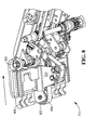
- Figures 4 to 6 show the bridge mechanism 314 in an extended configuration and Figures 7 to 9 show the bridge mechanism 314 in a retracted configuration.
- the second bridge portion 418 is moveable relative to the first bridge portion 416 to adjust the length of the bridge mechanism 314.
- a respective edge portion 550 of the first bridge portion 416 is pivotally attached to a drive roller shaft 352 of the lower transport member 302 of the first pair of transport members 302, 303.
- a respective edge portion 554 of the second bridge portion 418 includes a plurality of hook formations 456 to pivotally attach to a drive roller shaft 358 (as best shown in Figures 3 and 4 ) of the lower transport member 304 of the second pair of transport members 304, 305.
- the first bridge portion 416 has a centrally located main body 520 including opposed elongate channel formations 522 longitudinally oriented in the direction of the transport path 202, 204.
- the second bridge portion 418 includes a centrally located main body 540 including a pair of opposed outwardly extending longitudinal flanges 542 which are correspondingly shaped with the channel formations 522 of the first bridge portion 416.
- the channel formations 522 of the first bridge portion 416 receive, support and guide the flanges 542 of the second bridge portion 418 so the that second bridge portion 418 is supported and guided by the first bridge portion 416 when moving relative to the first bridge portion 416 between extended and retracted positions.
- a pair of spaced apart lugs 524 extend downwardly from the main body 520 of the first bridge portion 416 to support a pair of spaced apart secondary rollers 626, 628.
- the main body 540 of the second bridge portion 418 includes a pair of spaced apart and longitudinally extending lugs 460 to support a primary roller 662.
- the main body 540 of the second bridge portion 418 also includes a pair of spaced apart downwardly extending lugs 544 to support a single secondary roller 646.
- a drive roller 666 is mounted to the drive roller shaft 352 of the lower transport member 302 of the first pair of transport members 302, 303.
- a transport belt 464 extends around the drive roller 666 of the lower transport member 302 of the first pair of transport members 302, 303, around the secondary rollers 626, 628 of the first bridge portion 416, and around the primary roller 662 and secondary roller 646 of the second bridge portion 418.
- the drive roller 666 drives the belt 464 in the feed or return directions responsive to the desired transport path 202, 204 along which a media item is to be transported.
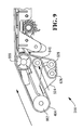
- FIGS 6 and 9 illustrate the bridge mechanism 314 in the extended and retracted configurations respectively.
- the secondary roller 646 of the second bridge portion 418 moves with respect to the secondary rollers 626, 628 of the first bridge portion 416 as the second bridge portion 418 moves with respect to the first bridge portion 416.
- the belt 464 is made from an elastic material, such as rubber, to accommodate for any stretch and to ensure the tension in the belt 464 is constant.
- a material such as rubber also has a coefficient of friction suitable for gripping a media item and urging the media item along the transport path 202, 204.
- the belt 464 passes between the lugs 544 of the second bridge portion 418 which help to guide and prevent the belt from slipping from the rollers.
- the first bridge portion 416 has a pair of arms 534 which extend outwardly from the main body 520 in a perpendicular direction with respect to the transport path 202, 204.
- a first set of elongate ribs 436 extend longitudinally from each arm 534 towards the second bridge portion 418 in a substantially parallel direction to the transport path 202, 204.
- the second bridge portion 418 has a pair of sheet-like arms 546 which extend outwardly from the main body 540 in a perpendicular direction with respect to the transport path 202, 204.
- a further set of elongate ribs 448 extend upwardly from each of the arms 546.
- Each of the first and further sets of elongate ribs 436, 448 are spaced apart such that the first set of ribs 436 is staggered with respect to the further set of ribs 448 to allow each of the further set of ribs 448 to slide between respective ribs of the first set of ribs 436 when the second bridge portion 418 moves with respect to the first bridge portion 416.
- the first and further sets of ribs 436, 448 support and guide at least one media item across the bridge mechanism 314 and along the transport path 202, 204.
- the bridge mechanism 314 therefore supports and guides at least one media item across respective end regions of spaced apart respective transport members and along a predetermined transport path.
- the bridge mechanism provides a continuous transport path irrespective of one of the transport members moving towards or away from the other of the transport members.
- the bridge mechanism provides a relatively long continuous transport path to allow a relatively long media item to be returned along the return transport path from left to right to be located in the transport mechanism without a leading end of the media item extending beyond the infeed end region 301 or the exit end region 307.
- the second pair of transport members are in turn allowed to reorient from the return position to the infeed position before transporting the media item along the infeed transport path from right to left for reprocessing.
- the bridge mechanism is self-adjusting so that its length can automatically adjust responsive to a one of the transport members moving towards or away from the other of the transport members. Such self-adjustment eliminates the need for re-locating and/or re-orienting one or both of the transport members to close a gap between respective end regions of each transport member.
- the bridge mechanism includes a driven transport belt to urge a media item across the bridge mechanism and along the transport path. The bridge mechanism ensures the length and tension of the belt is kept constant during said automatic adjustment of the length of the bridge mechanism.
Landscapes
- Engineering & Computer Science (AREA)
- Mechanical Engineering (AREA)
- Physics & Mathematics (AREA)
- General Physics & Mathematics (AREA)
- Business, Economics & Management (AREA)
- Accounting & Taxation (AREA)
- Finance (AREA)
- Delivering By Means Of Belts And Rollers (AREA)
- Feeding Of Articles By Means Other Than Belts Or Rollers (AREA)
- Registering Or Overturning Sheets (AREA)
Abstract
Description
- The present invention relates to a method and apparatus for transporting items of media along a transport path. In particular, but not exclusively, the present invention relates to transporting items of media, such as currency notes, across a gap between spaced apart transport members of a media item processing module.
- Various situations are known in which items of media are transported along different transport pathways in a Self-Service Terminal (SST). In a typical document depositing Automated Teller Machine (ATM), an ATM customer is allowed to deposit banknotes and/or a cheque (without having to place the cheque in a deposit envelope) in a publicly accessible, unattended environment. To deposit a cheque, the ATM customer inserts an identification card through a card slot at the ATM, enters the amount of the cheque being deposited, and inserts the cheque to be deposited through a cheque slot of a cheque acceptor. A cheque transport mechanism receives the inserted cheque and transports the cheque in a forward direction along an 'infeed' cheque transport path to a number of locations within the ATM to process the cheque.
- If the cheque is not accepted for deposit, the cheque transport mechanism transports the cheque in a reverse direction along a 'return' cheque transport path to return the cheque to the ATM customer via the cheque slot.
- If the cheque is accepted for deposit, an amount associated with the cheque is deposited into the ATM customer's account and the cheque itself is transported to a storage bin within the ATM. An endorser printer prints an endorsement onto the cheque as the cheque is being transported to and stored in the storage bin. Cheques in the storage bin within the ATM are periodically picked up and physically transported via courier to a back office facility of a financial institution for further processing.
- It is known for a cheque transport mechanism to include a first transport member and a second transport member for transporting one or more cheques along the infeed or return transport paths. It is known for the infeed transport path to be differently orientated with respect to the return transport path so the second transport member is moveable relative to the first transport member to move between infeed and return positions to thereby direct one or more cheques along the infeed or return transport paths as desired.
- A gap between respective end regions of the first and second transport members changes as the second transport member moves with respect to the first transport member between infeed and return positions. One or more problems therefore exist relating to how to transport media items from the first transport member to the second transport member, or vice versa, over this gap which may have a variable length and orientation. Such problems also relate to how media items are transported along the infeed or return transport path to prevent an error occurring during a customer transaction at the ATM which might lead to cheques being damaged during said transaction.
- It is an aim of the present invention to at least partly mitigate the above-mentioned problems.
- It is an aim of certain embodiments of the present invention to provide a method and apparatus for transporting an item of media along at least one transport path to and from a customer of an SST.
- It is an aim of certain embodiments of the present invention to provide a method and apparatus for transporting an item of media across a space between first and further transport members of a media item processing module.
- It is an aim of certain embodiments of the present invention to provide a self-adjusting apparatus for bridging a variable space between first and further transport members of a media item processing module.
- According to a first aspect of the present invention there is provided apparatus for transporting an item of media along at least one transport path, comprising:
- a first transport member having a first end region and a further transport member having a further end region, wherein the first end region is spaced apart from the further end region; and
- a bridge member extending between the first end region and the further end region, wherein a length of the bridge member is adjustable responsive to a one of the first and further end regions being moved with respect to a remainder one of the first and further end regions.
- Aptly, the bridge member comprises a first bridge portion and a further bridge portion, and the first bridge portion is automatically moveable towards or away from the further bridge portion responsive to an adjustment of the length of the bridge member.
- Aptly, the further bridge portion comprises at least one track that supports and guides the first bridge portion as the first bridge portion automatically moves with respect to the further bridge portion.
- Aptly, the at least one track of the further bridge portion comprises at least one elongate channel, and the first bridge portion comprises a guided region, extending from the first bridge portion, that is received by and guided along the elongate channel responsive to the first bridge portion being moved with respect to the further bridge portion.
- Aptly, the further bridge portion comprises:
- a central portion disposed on a longitudinal axis of the bridge member, wherein the central portion of the further bridge portion comprises the at least one elongate channel;
- a pair of support members each perpendicularly extending from the central portion with respect to the longitudinal axis; and
- at least one further track perpendicularly extending from each of the pair of support members to support the first bridge portion.
- Aptly, the first bridge portion comprises:
- a central portion disposed on the longitudinal axis of the bridge member, wherein the central portion of the first bridge portion comprises the guided region; and
- a pair of support members each perpendicularly extending from the central portion with respect to the longitudinal axis to be supported by the further tracks of the further bridge portion.
- Aptly, the first bridge portion comprises a first set of spaced apart elongate ribs and the further bridge portion comprises a further set of spaced apart elongate ribs, wherein the first and further sets of elongate ribs support an item of media being transported across the bridge member, and the first set of ribs is received between respective ribs of the further set of ribs when the first bridge portion is moved with respect to the further bridge portion.
- Aptly, the first bridge portion is pivotally attached to the first end region of the first transport member and the further bridge portion is pivotally attached to the further end region of the further transport member to allow for rotational movement of the first and/or further transport members with respect to the bridge member.
- Aptly, the first and/or further bridge portion is releasably attached to the first and/or further transport member respectively.
- Aptly, the first and/or further bridge portion comprises a plurality of hook members that releasably attach the bridge member to a roller shaft of the first and/or further transport member.
- Aptly, the apparatus further comprises a drive member that transports an item of media across the bridge member along a transport path between the first end region and the further end region.
- Aptly, the drive member comprises at least one drive belt supported on a plurality of rollers, wherein the drive belt is elastic to accommodate an adjustment of the length of the bridge member.
- Aptly, the plurality of rollers comprise at least one roller associated with the first bridge portion and at least one further roller associated with the further bridge portion.
- Aptly, the apparatus further comprises:
- a first transport unit comprising the first transport member and a first opposed transport member facing the first transport member for locating an item of media between the first transport member and the first opposed transport member; and
- a further transport unit comprising the further transport member and a further opposed transport member facing the further transport member for locating an item of media between the further transport member and the further opposed transport member, wherein an item of media is transportable along the transport path between the first transport unit and the further transport unit. Aptly, the first opposed transport member is pivotally attached to the further opposed transport member.
- Aptly, the first transport member is moveable with respect to the first opposed transport member between an open configuration and a closed configuration of the first transport unit responsive to an item of media being located between the first transport member and the first opposed transport member, and the further transport member is moveable with respect to the further opposed transport member between an open configuration and a closed configuration of the further transport unit responsive to an item of media being located between the further transport member and the further opposed transport member.
- According to a second aspect of the present invention there is provided a media item processing module comprising apparatus according to the first aspect of the present invention.
- According to a third aspect of the present invention there is provided a Self-Service Terminal (SST) comprising a media item processing module according to the second aspect of the present invention.
- According to a fourth aspect of the present invention there is provided a method of transporting an item of media along at least one transport path, comprising:
- via a bridge member, connecting a first end region of a first transport member to a further end region of a further transport member;
- moving at least one of the first and further end regions with respect to a remainder one of the first and further end regions; and
- adjusting a length of the bridge member responsive to said movement of the first and/or further end regions.
- Aptly, the adjusting step comprises:
- automatically moving a first bridge portion of the bridge member towards or away from a further bridge portion of the bridge member responsive to an adjustment of the length of the bridge member.
- Aptly, the method further comprises: via a drive member, transporting an item of media across the bridge member between the first end region of the first transport member and the further end region of the further transport member.
- Aptly, the method further comprises: maintaining a substantially constant tension in the drive member during the step of adjusting the length of the bridge member, wherein the drive member comprises an elastic drive belt.
- According to a fifth aspect of the present invention there is provided a method of transporting an item of media along at least one transport path, comprising:
- via an adjustable bridge member, connecting a first transport member to a further transport member to provide a continuous transport path for an item of media to be transported along, wherein at least one of the first and further transport members is moveable with respect to a remainder one of the first and further transport members.
- According to a sixth aspect of the present invention there is provided apparatus for transporting an item of media along at least one transport path, comprising:
- a first transport member spaced apart from, and moveable with respect to, a further transport member; and
- an adjustable bridge member for bridging a space between the first and further transport members.
- According to a seventh aspect of the present invention there is provided an infeed for a media handler, the infeed comprising:
- a customer transport for receiving a bunch of media items from, and presenting a bunch of media items to, a customer;
- a dual path transport moveable between a first position at which media items can be routed from the customer transport to a media item validator, and a second position at which media items can be routed from a return path to the customer transport;
- a pivotable bridge extendable between a retracted position and an extended position for bridging a space between the customer transport and the dual path transport at each of the first and second positions.
- Certain embodiments of the present invention provide a method and apparatus for transporting an item of media along at least one transport path to and from a customer of an SST.
- Certain embodiments of the present invention provide a method and apparatus for transporting an item of media across a space between first and further transport members of a media item processing module.
- Certain embodiments of the present invention provide a self-adjusting apparatus for bridging a variable space between first and further transport members of a media item processing module.
- Embodiments of the present invention will now be described hereinafter, by way of example only, with reference to the accompanying drawings in which:
-
Figure 1 illustrates an ATM according to an embodiment of the present invention; -
Figure 2 illustrates a removable document deposit module for use within the ATM ofFigure 1 according to an embodiment of the present invention; -
Figure 3 illustrates a media item transport mechanism located within the document deposit module ofFigure 2 , according to an embodiment of the present invention; -
Figure 4 illustrates an upper view of a bridge mechanism of the media item transport mechanism ofFigure 3 , wherein the bridge mechanism is in an extended configuration; -
Figure 5 illustrates a lower view of the bridge mechanism ofFigure 4 ; -
Figure 6 illustrates a longitudinal cross section through the bridge mechanism ofFigures 4 and5 ; -
Figure 7 illustrates an upper view of the bridge mechanism of the media item transport mechanism ofFigure 3 , wherein the bridge mechanism is in a retracted configuration; -
Figure 8 illustrates a lower view of the bridge mechanism ofFigure 7 ; and -
Figure 9 illustrates a longitudinal cross section through the bridge mechanism ofFigures 7 and8 . - In the drawings like reference numerals refer to like parts.
-
Figure 1 illustrates a self-service document (cheque and banknote) depositing terminal in the form of an image-based document depositing Automated Teller Machine (ATM) 100. It will be appreciated that certain embodiments of the present invention are applicable to a wide variety of terminals in which items of media such as cheques and/or currency notes and/or giros and/or lottery tickets and/or other such flexible sheet-like items of media are to be transported and directed in different directions. The type of terminal will of course be appropriate for the type of items of media being transported. - As illustrated in
Figure 1 , theATM 100 includes afascia 101 coupled to a chassis (not shown). Thefascia 101 defines anaperture 102 through which a camera (not shown) images a customer of theATM 100. Thefascia 101 also defines a number of slots for receiving and dispensing media items and atray 103 into which coins can be dispensed. The slots include astatement output slot 104, areceipt slot 105, acard reader slot 106, acash slot 107, afurther cash slot 108 and a cheque input/output slot 110. The slots and tray are arranged such that the slots and tray align with corresponding ATM modules mounted within the chassis of the ATM. - The
fascia 101 provides a customer interface for allowing an ATM customer to execute a transaction. Thefascia 101 includes an encryptingkeyboard 120 for allowing an ATM customer to enter transaction details. Adisplay 130 is provided for presenting screens to an ATM customer. Anoptional fingerprint reader 140 may be provided for reading a fingerprint of an ATM customer to identify the ATM customer. - Within the chassis of the ATM it will be understood that items of media must be transported from time to time from one location to another. The pathway taken by any particular item of media is dependent upon an operation being carried out at the ATM and may also be dependent upon other factors such as whether a customer of the ATM is authorised and/or whether an item of media being transported satisfies certain pre-determined criteria.
-
Figure 2 illustrates adocument processing module 200 providing possible transport pathways within the ATM which can be utilised to process deposited cheques and banknotes (either individually or as a mixed bunch). Thedocument processing module 200 has anaccess mouth 201 through which incoming cheques and/or currency notes are deposited or outgoing cheques are dispensed. Thismouth 201 is aligned with an infeed aperture in the ATM which thus provides an input/output slot 110. A bunch of one or more media items, such as currency notes or cheques, is input or output. Aptly, a bunch of a hundred items or more can be received/dispensed. Incoming cheques follow afirst transport path 202 away from themouth 201 in a substantially horizontal direction from right to left shown inFigure 2 . Thefirst transport path 202 is also referred to as the infeed path. The cheques then pass through a feeder/separator 203 and along anotherpathway portion 205 which is also substantially horizontal and right to left. The cheques are then de-skewed and read by imagingcameras 206 and anMICR reader 207. Cheques are then directed substantially vertically downwards to a point between two niprollers 208. These nip rollers co-operate and are rotated in opposite directions with respect to each other to either draw deposited cheques inwards (and urge those cheques towards the right hand side inFigure 2 ), or during another mode of operation, the rollers can be rotated in an opposite fashion to direct processed cheques downwards in the direction shown by arrow A inFigure 2 into acheque bin 210. Incoming cheques which are moved by thenip rollers 208 towards the right can either be diverted upwards (inFigure 2 ) into are-buncher unit 225, or downwards in the direction of arrow B inFigure 2 into acash bin 230, or to the right hand side shown inFigure 2 into anescrow 240. Cheques from the escrow can be directed to the re-buncher 225 or downwards into thecash bin 230. Cheques can be reprocessed or returned to a customer via afurther transport path 204, also known as the return path. - As illustrated in
Figure 3 , a mediaitem transport mechanism 300 includes a first pair ofopposed transport members Figure 3 and a second pair ofopposed transport members Figure 3 . The pairs of transport members provide apredetermined transport path transport mechanism 300. - An
infeed end region 301 of the first pair oftransport members access mouth 201 of thedocument processing module 200. The second pair oftransport members transport members infeed path 202 or returnpath 204 as desired. Anend region 307 of the second pair oftransport members separator 203 when in the infeed position for transporting media items along theinfeed path 202. - Each of the
transport members respective transport belt transport path transport path - Each pair of
transport members transport mechanism 300 and along thetransport path - The
lower transport member 304 of the second pair oftransport members Figure 3 is rotatable about axis A with respect to thelower transport member 302 of the first pair oftransport members upper transport member 305 of the second pair oftransport members upper transport member 303 of the first pair oftransport members lower transport members transport members lower transport member 304 of the second pair oftransport members lower transport member 302 of the first pair oftransport members transport mechanism 300 and along theinfeed transport path 202 to be processed in themodule 200, and a return position, wherein media items are moved from left to right through thetransport mechanism 300 and along thereturn transport path 204 to be reprocessed along the infeed path or returned to a customer. - The first and second pairs of
transport members Figure 3 are in a return configuration wherein the second pair oftransport members transport members return transport path 204 from left to right and towards themouth 201 of the mediaitem processing module 200. Both pairs oftransport members return transport path 204. - A
bridge mechanism 314 is provided between spaced apart end portions of the respectivelower transport members transport members bridge mechanism 314 is hingedly coupled to the respectivelower transport members transport members lower transport member 304 of the first pair oftransport members lower transport member 302 of the second pair oftransport members transport members - As will be understood, the
transport mechanism 300 can be placed in any one of a number of configurations depending on the desiredtransport path transport mechanism 300 and/or the thickness of a bunch of media items to be or being transported through thetransport mechanism 300. Hence, the horizontal distance X and the vertical distance Y between axes A and B varies depending on the configuration of thetransport mechanism 300 and more specifically the orientation oflower transport member 304 with respect tolower transport member 302. In turn, a distance (corresponding to bridge length L) directly between axes A and B also changes. Dimension Y can change by around 35mm and dimension X can change by around 25mm depending on the configuration of the transport mechanism. In turn, distance L can change by around 20mm from a minimum of around 44mm to a maximum of around 64mm. To accommodate for the angle of the second pair oftransport members transport members lower transport members bridge mechanism 314 is automatically adjustable. - As shown in
Figure 4 , thebridge mechanism 314 includes two main portions; afirst bridge portion 416 and asecond bridge portion 418. The first andsecond bridge portions bridge mechanism 314 can automatically adjust in response to respective end regions of thelower transport members transport mechanism 300. -
Figures 4 to 6 show thebridge mechanism 314 in an extended configuration andFigures 7 to 9 show thebridge mechanism 314 in a retracted configuration. - The
second bridge portion 418 is moveable relative to thefirst bridge portion 416 to adjust the length of thebridge mechanism 314. - A
respective edge portion 550 of thefirst bridge portion 416 is pivotally attached to adrive roller shaft 352 of thelower transport member 302 of the first pair oftransport members respective edge portion 554 of thesecond bridge portion 418 includes a plurality ofhook formations 456 to pivotally attach to a drive roller shaft 358 (as best shown inFigures 3 and4 ) of thelower transport member 304 of the second pair oftransport members - As best shown in
Figures 5 and6 , thefirst bridge portion 416 has a centrally locatedmain body 520 including opposedelongate channel formations 522 longitudinally oriented in the direction of thetransport path second bridge portion 418 includes a centrally locatedmain body 540 including a pair of opposed outwardly extendinglongitudinal flanges 542 which are correspondingly shaped with thechannel formations 522 of thefirst bridge portion 416. Thechannel formations 522 of thefirst bridge portion 416 receive, support and guide theflanges 542 of thesecond bridge portion 418 so the thatsecond bridge portion 418 is supported and guided by thefirst bridge portion 416 when moving relative to thefirst bridge portion 416 between extended and retracted positions. - As best shown in
Figure 6 , a pair of spaced apart lugs 524 extend downwardly from themain body 520 of thefirst bridge portion 416 to support a pair of spaced apartsecondary rollers main body 540 of thesecond bridge portion 418 includes a pair of spaced apart and longitudinally extendinglugs 460 to support aprimary roller 662. Themain body 540 of thesecond bridge portion 418 also includes a pair of spaced apart downwardly extendinglugs 544 to support a singlesecondary roller 646. Adrive roller 666 is mounted to thedrive roller shaft 352 of thelower transport member 302 of the first pair oftransport members - A
transport belt 464 extends around thedrive roller 666 of thelower transport member 302 of the first pair oftransport members secondary rollers first bridge portion 416, and around theprimary roller 662 andsecondary roller 646 of thesecond bridge portion 418. Thedrive roller 666 drives thebelt 464 in the feed or return directions responsive to the desiredtransport path -
Figures 6 and9 illustrate thebridge mechanism 314 in the extended and retracted configurations respectively. As shown, thesecondary roller 646 of thesecond bridge portion 418 moves with respect to thesecondary rollers first bridge portion 416 as thesecond bridge portion 418 moves with respect to thefirst bridge portion 416. This ensures the length and tension of thebelt 464 are kept constant as thebridge mechanism 314 self-adjusts in response thelower transport member 304 of the second pair oftransport members lower transport member 302 of the first pair oftransport members belt 464 is made from an elastic material, such as rubber, to accommodate for any stretch and to ensure the tension in thebelt 464 is constant. A material such as rubber also has a coefficient of friction suitable for gripping a media item and urging the media item along thetransport path belt 464 passes between thelugs 544 of thesecond bridge portion 418 which help to guide and prevent the belt from slipping from the rollers. - The
first bridge portion 416 has a pair ofarms 534 which extend outwardly from themain body 520 in a perpendicular direction with respect to thetransport path elongate ribs 436 extend longitudinally from eacharm 534 towards thesecond bridge portion 418 in a substantially parallel direction to thetransport path second bridge portion 418 has a pair of sheet-like arms 546 which extend outwardly from themain body 540 in a perpendicular direction with respect to thetransport path - A further set of
elongate ribs 448 extend upwardly from each of thearms 546. Each of the first and further sets ofelongate ribs ribs 436 is staggered with respect to the further set ofribs 448 to allow each of the further set ofribs 448 to slide between respective ribs of the first set ofribs 436 when thesecond bridge portion 418 moves with respect to thefirst bridge portion 416. The first and further sets ofribs bridge mechanism 314 and along thetransport path - The
bridge mechanism 314 according to certain embodiments of the present invention therefore supports and guides at least one media item across respective end regions of spaced apart respective transport members and along a predetermined transport path. The bridge mechanism provides a continuous transport path irrespective of one of the transport members moving towards or away from the other of the transport members. The bridge mechanism provides a relatively long continuous transport path to allow a relatively long media item to be returned along the return transport path from left to right to be located in the transport mechanism without a leading end of the media item extending beyond theinfeed end region 301 or theexit end region 307. The second pair of transport members are in turn allowed to reorient from the return position to the infeed position before transporting the media item along the infeed transport path from right to left for reprocessing. The bridge mechanism is self-adjusting so that its length can automatically adjust responsive to a one of the transport members moving towards or away from the other of the transport members. Such self-adjustment eliminates the need for re-locating and/or re-orienting one or both of the transport members to close a gap between respective end regions of each transport member. The bridge mechanism includes a driven transport belt to urge a media item across the bridge mechanism and along the transport path. The bridge mechanism ensures the length and tension of the belt is kept constant during said automatic adjustment of the length of the bridge mechanism. - Throughout the description and claims of this specification, the words "comprise" and "contain" and variations of them mean "including but not limited to" and they are not intended to (and do not) exclude other moieties, additives, components, integers or steps. Throughout the description and claims of this specification, the singular encompasses the plural unless the context otherwise requires. In particular, where the indefinite article is used, the specification is to be understood as contemplating plurality as well as singularity, unless the context requires otherwise.
- Features, integers, characteristics or groups described in conjunction with a particular aspect, embodiment or example of the invention are to be understood to be applicable to any other aspect, embodiment or example described herein unless incompatible therewith. All of the features disclosed in this specification (including any accompanying claims, abstract and drawings), and/or all of the steps of any method or process so disclosed, may be combined in any combination, except combinations where at least some of the features and/or steps are mutually exclusive. The invention is not restricted to any details of any foregoing embodiments.
Claims (14)
- Apparatus (300) for transporting an item of media along at least one transport path (202, 204), comprising:a first transport member (302 or 303) having a first end region and a further transport member (304 or 305) having a further end region, wherein the first end region is spaced apart from the further end region; anda bridge member (314) extending between the first end region and the further end region, wherein a length (L) of the bridge member (314) is adjustable responsive to a one of the first and further end regions being moved with respect to a remainder one of the first and further end regions.
- The apparatus as claimed in claim 1, wherein the bridge member (314) comprises a first bridge portion (418) and a further bridge portion (416), and the first bridge portion (418) is automatically moveable towards or away from the further bridge portion (416) responsive to an adjustment of the length of the bridge member (314).
- The apparatus as claimed in claim 2, wherein the further bridge portion (416) comprises at least one track (522) that supports and guides the first bridge portion (418) as the first bridge portion (418) automatically moves with respect to the further bridge portion (416).
- The apparatus as claimed in claim 3, wherein the at least one track (522) of the further bridge portion (416) comprises at least one elongate channel (522), and the first bridge portion (418) comprises a guided region (542), extending from the first bridge portion (418), that is received by and guided along the elongate channel (522) responsive to the first bridge portion (418) being moved with respect to the further bridge portion (416).
- The apparatus as claimed in claim 4, wherein the further bridge portion (416) comprises:a central portion (520) disposed on a longitudinal axis of the bridge member (314), wherein the central portion (520) of the further bridge portion (416) comprises the at least one elongate channel (522);a pair of support members (534) each perpendicularly extending from the central portion (520) with respect to the longitudinal axis; andat least one further track perpendicularly extending from each of the pair of support members (534) to support the first bridge portion (418).
- The apparatus as claimed in claim 5, wherein the first bridge portion (418) comprises:a central portion (540) disposed on the longitudinal axis of the bridge member (314), wherein the central portion (540) of the first bridge portion (418) comprises the guided region (542); anda pair of support members (546) each perpendicularly extending from the central portion (540) with respect to the longitudinal axis to be supported by the further tracks of the further bridge portion (416).
- The apparatus as claimed in claim 6, wherein the first bridge portion (418) comprises a first set of spaced apart elongate ribs (448) and the further bridge portion (416) comprises a further set of spaced apart elongate ribs (436), wherein the first and further sets of elongate ribs (448, 436) support an item of media being transported across the bridge member (314), and the first set of ribs (448) is received between respective ribs (436) of the further set of ribs (436) when the first bridge portion (418) is moved with respect to the further bridge portion (416).
- The apparatus as claimed in any of claims 2 to 7, wherein the first bridge portion (418) is pivotally attached to the first end region of the first transport member (302 or 304) and the further bridge portion (416) is pivotally attached to the further end region of the further transport member (304 or 302) to allow for rotational movement of the first and/or further transport members (302 or 304) with respect to the bridge member (314).
- The apparatus as claimed in any preceding claim, further comprising a drive member that transports an item of media across the bridge member (314) along a transport path (202 or 204) between the first end region of the first transport member (302 or 304) and the further end region of the further transport member (304 or 302).
- The apparatus as claimed in any preceding claim, further comprising:a first transport unit comprising the first transport member (302 or 304) and a first opposed transport member (303 or 305) facing the first transport member (302 or 304) for locating an item of media between the first transport member (302 or 304) and the first opposed transport member (303 or 305); anda further transport unit comprising the further transport member (304 or 302) and a further opposed transport member (305 or 303) facing the further transport member (304 or 302) for locating an item of media between the further transport member (304 or 302) and the further opposed transport member (305 or 303), wherein an item of media is transportable along the transport path between the first transport unit and the further transport unit.
- A media item processing module (200) comprising apparatus (300) as claimed in any preceding claim.
- A method of transporting an item of media along at least one transport path (202 or 204), the method comprising:via a bridge member (314), connecting a first end region of a first transport member (302 or 304) to a further end region of a further transport member (304 or 302);moving at least one of the first and further end regions with respect to a remainder one of the first and further end regions; andadjusting a length of the bridge member (314) responsive to said movement of the first and/or further end regions.
- The method as claimed in claim 12, wherein the adjusting step comprises:automatically moving a first bridge portion (418) of the bridge member (314) towards or away from a further bridge portion (416) of the bridge member (314) responsive to an adjustment of the length of the bridge member (314).
- The method as claimed in claim 12 or 13, further comprising:via a drive member (666), transporting an item of media across the bridge member between the first end region of the first transport member and the further end region of the further transport member.
Applications Claiming Priority (1)
| Application Number | Priority Date | Filing Date | Title |
|---|---|---|---|
| US13/955,472 US9082246B2 (en) | 2013-07-31 | 2013-07-31 | Media item transportation |
Publications (3)
| Publication Number | Publication Date |
|---|---|
| EP2832673A2 true EP2832673A2 (en) | 2015-02-04 |
| EP2832673A3 EP2832673A3 (en) | 2015-07-15 |
| EP2832673B1 EP2832673B1 (en) | 2016-08-17 |
Family
ID=51063264
Family Applications (1)
| Application Number | Title | Priority Date | Filing Date |
|---|---|---|---|
| EP14173080.4A Active EP2832673B1 (en) | 2013-07-31 | 2014-06-19 | Apparatus for transporting an item of media, media item processing module, and method of transporting an item of media |
Country Status (4)
| Country | Link |
|---|---|
| US (1) | US9082246B2 (en) |
| EP (1) | EP2832673B1 (en) |
| CN (1) | CN104346861B (en) |
| BR (1) | BR102014018830B1 (en) |
Families Citing this family (7)
| Publication number | Priority date | Publication date | Assignee | Title |
|---|---|---|---|---|
| US9861346B2 (en) | 2003-07-14 | 2018-01-09 | W. L. Gore & Associates, Inc. | Patent foramen ovale (PFO) closure device with linearly elongating petals |
| WO2008124603A1 (en) | 2007-04-05 | 2008-10-16 | Nmt Medical, Inc. | Septal closure device with centering mechanism |
| US8956389B2 (en) | 2009-06-22 | 2015-02-17 | W. L. Gore & Associates, Inc. | Sealing device and delivery system |
| US20120029556A1 (en) | 2009-06-22 | 2012-02-02 | Masters Steven J | Sealing device and delivery system |
| US10828019B2 (en) | 2013-01-18 | 2020-11-10 | W.L. Gore & Associates, Inc. | Sealing device and delivery system |
| US9472041B2 (en) * | 2013-10-31 | 2016-10-18 | Ncr Corporation | Clamping of media items |
| US11127244B2 (en) * | 2018-05-25 | 2021-09-21 | Ags Llc | Universal adjustable printer bezel |
Family Cites Families (7)
| Publication number | Priority date | Publication date | Assignee | Title |
|---|---|---|---|---|
| DE3114102A1 (en) * | 1980-04-09 | 1982-02-25 | DRG (UK) Ltd., Bristol | Process and device for feeding sheets of paper, cardboard or the like |
| JPH03162361A (en) * | 1989-11-20 | 1991-07-12 | Toshiba Corp | Gathering device |
| US5326093A (en) * | 1993-05-24 | 1994-07-05 | Xerox Corporation | Universal interface module interconnecting various copiers and printers with various sheet output processors |
| JP4007799B2 (en) * | 2001-11-22 | 2007-11-14 | グローリー株式会社 | Banknote deposit device |
| US7422118B2 (en) * | 2003-12-16 | 2008-09-09 | Cts Cashpro, S.P.A. | Equipment for the automatic deposit of banknotes |
| JP2007249475A (en) * | 2006-03-15 | 2007-09-27 | Mitsubishi Electric Corp | Image reading apparatus and bill reading method |
| JP5122325B2 (en) * | 2008-02-26 | 2013-01-16 | 日立オムロンターミナルソリューションズ株式会社 | Paper sheet transport mechanism and paper sheet handling device |
-
2013
- 2013-07-31 US US13/955,472 patent/US9082246B2/en active Active
-
2014
- 2014-06-19 EP EP14173080.4A patent/EP2832673B1/en active Active
- 2014-07-24 CN CN201410356041.4A patent/CN104346861B/en active Active
- 2014-07-30 BR BR102014018830-4A patent/BR102014018830B1/en active IP Right Grant
Non-Patent Citations (1)
| Title |
|---|
| None |
Also Published As
| Publication number | Publication date |
|---|---|
| US20150034452A1 (en) | 2015-02-05 |
| EP2832673B1 (en) | 2016-08-17 |
| EP2832673A3 (en) | 2015-07-15 |
| US9082246B2 (en) | 2015-07-14 |
| BR102014018830A2 (en) | 2015-11-17 |
| CN104346861B (en) | 2017-04-05 |
| CN104346861A (en) | 2015-02-11 |
| BR102014018830B1 (en) | 2021-12-28 |
Similar Documents
| Publication | Publication Date | Title |
|---|---|---|
| EP2832673B1 (en) | Apparatus for transporting an item of media, media item processing module, and method of transporting an item of media | |
| CN101520913B (en) | Paper transport mechanism and paper handling device | |
| EP2835330B1 (en) | Clamping of media items | |
| US8556254B2 (en) | Paper sheet handling apparatus | |
| US8939449B2 (en) | Sheet transport apparatus facilitating establishing a continuous sheet transport path | |
| EP2287099B1 (en) | Document Deskewing | |
| EP2832672B1 (en) | Method and apparatus for media item transportation | |
| EP2687467A2 (en) | Transport apparatus | |
| JP5647798B2 (en) | Paper handling equipment | |
| US20130319816A1 (en) | Pathway selection | |
| WO2014155644A1 (en) | Paper sheet handling device and automatic transaction device | |
| CN103426230B (en) | Bill handling device and automatic trading apparatus | |
| US9472041B2 (en) | Clamping of media items | |
| US9171430B2 (en) | Media item transporter | |
| KR20180051722A (en) | Apparatus for changing of the bill transferring direction and Automated teller machine having the same | |
| US9302876B2 (en) | Media presenter | |
| US9990793B2 (en) | Media item separation | |
| KR20170011024A (en) | Diverter, medium processing apparatus and financial device | |
| JP2003155158A (en) | Paper storage and paper processing equipment | |
| KR101177945B1 (en) | Cash transaction machine having function for adjusting tension | |
| JP2019211972A (en) | Paper sheet processing device and paper sheet processing method | |
| KR101678892B1 (en) | Cassette apparatus of various bills | |
| JP2003157458A (en) | Banknote processing apparatus and banknote dispensing apparatus |
Legal Events
| Date | Code | Title | Description |
|---|---|---|---|
| 17P | Request for examination filed |
Effective date: 20140619 |
|
| AK | Designated contracting states |
Kind code of ref document: A2 Designated state(s): AL AT BE BG CH CY CZ DE DK EE ES FI FR GB GR HR HU IE IS IT LI LT LU LV MC MK MT NL NO PL PT RO RS SE SI SK SM TR |
|
| AX | Request for extension of the european patent |
Extension state: BA ME |
|
| PUAI | Public reference made under article 153(3) epc to a published international application that has entered the european phase |
Free format text: ORIGINAL CODE: 0009012 |
|
| PUAL | Search report despatched |
Free format text: ORIGINAL CODE: 0009013 |
|
| AK | Designated contracting states |
Kind code of ref document: A3 Designated state(s): AL AT BE BG CH CY CZ DE DK EE ES FI FR GB GR HR HU IE IS IT LI LT LU LV MC MK MT NL NO PL PT RO RS SE SI SK SM TR |
|
| AX | Request for extension of the european patent |
Extension state: BA ME |
|
| RIC1 | Information provided on ipc code assigned before grant |
Ipc: B65H 31/30 20060101AFI20150610BHEP Ipc: B65H 29/12 20060101ALI20150610BHEP |
|
| R17P | Request for examination filed (corrected) |
Effective date: 20160115 |
|
| RBV | Designated contracting states (corrected) |
Designated state(s): AL AT BE BG CH CY CZ DE DK EE ES FI FR GB GR HR HU IE IS IT LI LT LU LV MC MK MT NL NO PL PT RO RS SE SI SK SM TR |
|
| GRAP | Despatch of communication of intention to grant a patent |
Free format text: ORIGINAL CODE: EPIDOSNIGR1 |
|
| INTG | Intention to grant announced |
Effective date: 20160413 |
|
| GRAS | Grant fee paid |
Free format text: ORIGINAL CODE: EPIDOSNIGR3 |
|
| GRAA | (expected) grant |
Free format text: ORIGINAL CODE: 0009210 |
|
| AK | Designated contracting states |
Kind code of ref document: B1 Designated state(s): AL AT BE BG CH CY CZ DE DK EE ES FI FR GB GR HR HU IE IS IT LI LT LU LV MC MK MT NL NO PL PT RO RS SE SI SK SM TR |
|
| REG | Reference to a national code |
Ref country code: GB Ref legal event code: FG4D |
|
| REG | Reference to a national code |
Ref country code: DE Ref legal event code: R084 Ref document number: 602014003060 Country of ref document: DE |
|
| REG | Reference to a national code |
Ref country code: CH Ref legal event code: EP |
|
| REG | Reference to a national code |
Ref country code: IE Ref legal event code: FG4D |
|
| REG | Reference to a national code |
Ref country code: AT Ref legal event code: REF Ref document number: 820847 Country of ref document: AT Kind code of ref document: T Effective date: 20160915 |
|
| REG | Reference to a national code |
Ref country code: GB Ref legal event code: 746 Effective date: 20160901 |
|
| REG | Reference to a national code |
Ref country code: DE Ref legal event code: R096 Ref document number: 602014003060 Country of ref document: DE |
|
| REG | Reference to a national code |
Ref country code: NL Ref legal event code: MP Effective date: 20160817 |
|
| REG | Reference to a national code |
Ref country code: LT Ref legal event code: MG4D |
|
| REG | Reference to a national code |
Ref country code: AT Ref legal event code: MK05 Ref document number: 820847 Country of ref document: AT Kind code of ref document: T Effective date: 20160817 |
|
| PG25 | Lapsed in a contracting state [announced via postgrant information from national office to epo] |
Ref country code: NO Free format text: LAPSE BECAUSE OF FAILURE TO SUBMIT A TRANSLATION OF THE DESCRIPTION OR TO PAY THE FEE WITHIN THE PRESCRIBED TIME-LIMIT Effective date: 20161117 Ref country code: FI Free format text: LAPSE BECAUSE OF FAILURE TO SUBMIT A TRANSLATION OF THE DESCRIPTION OR TO PAY THE FEE WITHIN THE PRESCRIBED TIME-LIMIT Effective date: 20160817 Ref country code: HR Free format text: LAPSE BECAUSE OF FAILURE TO SUBMIT A TRANSLATION OF THE DESCRIPTION OR TO PAY THE FEE WITHIN THE PRESCRIBED TIME-LIMIT Effective date: 20160817 Ref country code: IT Free format text: LAPSE BECAUSE OF FAILURE TO SUBMIT A TRANSLATION OF THE DESCRIPTION OR TO PAY THE FEE WITHIN THE PRESCRIBED TIME-LIMIT Effective date: 20160817 Ref country code: RS Free format text: LAPSE BECAUSE OF FAILURE TO SUBMIT A TRANSLATION OF THE DESCRIPTION OR TO PAY THE FEE WITHIN THE PRESCRIBED TIME-LIMIT Effective date: 20160817 Ref country code: LT Free format text: LAPSE BECAUSE OF FAILURE TO SUBMIT A TRANSLATION OF THE DESCRIPTION OR TO PAY THE FEE WITHIN THE PRESCRIBED TIME-LIMIT Effective date: 20160817 Ref country code: NL Free format text: LAPSE BECAUSE OF FAILURE TO SUBMIT A TRANSLATION OF THE DESCRIPTION OR TO PAY THE FEE WITHIN THE PRESCRIBED TIME-LIMIT Effective date: 20160817 |
|
| PG25 | Lapsed in a contracting state [announced via postgrant information from national office to epo] |
Ref country code: AT Free format text: LAPSE BECAUSE OF FAILURE TO SUBMIT A TRANSLATION OF THE DESCRIPTION OR TO PAY THE FEE WITHIN THE PRESCRIBED TIME-LIMIT Effective date: 20160817 Ref country code: LV Free format text: LAPSE BECAUSE OF FAILURE TO SUBMIT A TRANSLATION OF THE DESCRIPTION OR TO PAY THE FEE WITHIN THE PRESCRIBED TIME-LIMIT Effective date: 20160817 Ref country code: ES Free format text: LAPSE BECAUSE OF FAILURE TO SUBMIT A TRANSLATION OF THE DESCRIPTION OR TO PAY THE FEE WITHIN THE PRESCRIBED TIME-LIMIT Effective date: 20160817 Ref country code: GR Free format text: LAPSE BECAUSE OF FAILURE TO SUBMIT A TRANSLATION OF THE DESCRIPTION OR TO PAY THE FEE WITHIN THE PRESCRIBED TIME-LIMIT Effective date: 20161118 Ref country code: PT Free format text: LAPSE BECAUSE OF FAILURE TO SUBMIT A TRANSLATION OF THE DESCRIPTION OR TO PAY THE FEE WITHIN THE PRESCRIBED TIME-LIMIT Effective date: 20161219 Ref country code: PL Free format text: LAPSE BECAUSE OF FAILURE TO SUBMIT A TRANSLATION OF THE DESCRIPTION OR TO PAY THE FEE WITHIN THE PRESCRIBED TIME-LIMIT Effective date: 20160817 Ref country code: SE Free format text: LAPSE BECAUSE OF FAILURE TO SUBMIT A TRANSLATION OF THE DESCRIPTION OR TO PAY THE FEE WITHIN THE PRESCRIBED TIME-LIMIT Effective date: 20160817 |
|
| PG25 | Lapsed in a contracting state [announced via postgrant information from national office to epo] |
Ref country code: RO Free format text: LAPSE BECAUSE OF FAILURE TO SUBMIT A TRANSLATION OF THE DESCRIPTION OR TO PAY THE FEE WITHIN THE PRESCRIBED TIME-LIMIT Effective date: 20160817 Ref country code: EE Free format text: LAPSE BECAUSE OF FAILURE TO SUBMIT A TRANSLATION OF THE DESCRIPTION OR TO PAY THE FEE WITHIN THE PRESCRIBED TIME-LIMIT Effective date: 20160817 |
|
| REG | Reference to a national code |
Ref country code: DE Ref legal event code: R097 Ref document number: 602014003060 Country of ref document: DE |
|
| PG25 | Lapsed in a contracting state [announced via postgrant information from national office to epo] |
Ref country code: DK Free format text: LAPSE BECAUSE OF FAILURE TO SUBMIT A TRANSLATION OF THE DESCRIPTION OR TO PAY THE FEE WITHIN THE PRESCRIBED TIME-LIMIT Effective date: 20160817 Ref country code: SK Free format text: LAPSE BECAUSE OF FAILURE TO SUBMIT A TRANSLATION OF THE DESCRIPTION OR TO PAY THE FEE WITHIN THE PRESCRIBED TIME-LIMIT Effective date: 20160817 Ref country code: SM Free format text: LAPSE BECAUSE OF FAILURE TO SUBMIT A TRANSLATION OF THE DESCRIPTION OR TO PAY THE FEE WITHIN THE PRESCRIBED TIME-LIMIT Effective date: 20160817 Ref country code: BE Free format text: LAPSE BECAUSE OF FAILURE TO SUBMIT A TRANSLATION OF THE DESCRIPTION OR TO PAY THE FEE WITHIN THE PRESCRIBED TIME-LIMIT Effective date: 20160817 Ref country code: BG Free format text: LAPSE BECAUSE OF FAILURE TO SUBMIT A TRANSLATION OF THE DESCRIPTION OR TO PAY THE FEE WITHIN THE PRESCRIBED TIME-LIMIT Effective date: 20161117 Ref country code: CZ Free format text: LAPSE BECAUSE OF FAILURE TO SUBMIT A TRANSLATION OF THE DESCRIPTION OR TO PAY THE FEE WITHIN THE PRESCRIBED TIME-LIMIT Effective date: 20160817 |
|
| PLBE | No opposition filed within time limit |
Free format text: ORIGINAL CODE: 0009261 |
|
| STAA | Information on the status of an ep patent application or granted ep patent |
Free format text: STATUS: NO OPPOSITION FILED WITHIN TIME LIMIT |
|
| REG | Reference to a national code |
Ref country code: FR Ref legal event code: PLFP Year of fee payment: 4 |
|
| 26N | No opposition filed |
Effective date: 20170518 |
|
| PG25 | Lapsed in a contracting state [announced via postgrant information from national office to epo] |
Ref country code: SI Free format text: LAPSE BECAUSE OF FAILURE TO SUBMIT A TRANSLATION OF THE DESCRIPTION OR TO PAY THE FEE WITHIN THE PRESCRIBED TIME-LIMIT Effective date: 20160817 |
|
| PG25 | Lapsed in a contracting state [announced via postgrant information from national office to epo] |
Ref country code: MC Free format text: LAPSE BECAUSE OF FAILURE TO SUBMIT A TRANSLATION OF THE DESCRIPTION OR TO PAY THE FEE WITHIN THE PRESCRIBED TIME-LIMIT Effective date: 20160817 |
|
| REG | Reference to a national code |
Ref country code: CH Ref legal event code: PL |
|
| REG | Reference to a national code |
Ref country code: IE Ref legal event code: MM4A |
|
| PG25 | Lapsed in a contracting state [announced via postgrant information from national office to epo] |
Ref country code: CH Free format text: LAPSE BECAUSE OF NON-PAYMENT OF DUE FEES Effective date: 20170630 Ref country code: LU Free format text: LAPSE BECAUSE OF NON-PAYMENT OF DUE FEES Effective date: 20170619 Ref country code: IE Free format text: LAPSE BECAUSE OF NON-PAYMENT OF DUE FEES Effective date: 20170619 Ref country code: LI Free format text: LAPSE BECAUSE OF NON-PAYMENT OF DUE FEES Effective date: 20170630 |
|
| REG | Reference to a national code |
Ref country code: FR Ref legal event code: PLFP Year of fee payment: 5 |
|
| PG25 | Lapsed in a contracting state [announced via postgrant information from national office to epo] |
Ref country code: MT Free format text: LAPSE BECAUSE OF NON-PAYMENT OF DUE FEES Effective date: 20170619 |
|
| PG25 | Lapsed in a contracting state [announced via postgrant information from national office to epo] |
Ref country code: AL Free format text: LAPSE BECAUSE OF FAILURE TO SUBMIT A TRANSLATION OF THE DESCRIPTION OR TO PAY THE FEE WITHIN THE PRESCRIBED TIME-LIMIT Effective date: 20160817 |
|
| PG25 | Lapsed in a contracting state [announced via postgrant information from national office to epo] |
Ref country code: HU Free format text: LAPSE BECAUSE OF FAILURE TO SUBMIT A TRANSLATION OF THE DESCRIPTION OR TO PAY THE FEE WITHIN THE PRESCRIBED TIME-LIMIT; INVALID AB INITIO Effective date: 20140619 |
|
| PG25 | Lapsed in a contracting state [announced via postgrant information from national office to epo] |
Ref country code: CY Free format text: LAPSE BECAUSE OF FAILURE TO SUBMIT A TRANSLATION OF THE DESCRIPTION OR TO PAY THE FEE WITHIN THE PRESCRIBED TIME-LIMIT Effective date: 20160817 |
|
| PG25 | Lapsed in a contracting state [announced via postgrant information from national office to epo] |
Ref country code: MK Free format text: LAPSE BECAUSE OF FAILURE TO SUBMIT A TRANSLATION OF THE DESCRIPTION OR TO PAY THE FEE WITHIN THE PRESCRIBED TIME-LIMIT Effective date: 20160817 |
|
| REG | Reference to a national code |
Ref country code: DE Ref legal event code: R081 Ref document number: 602014003060 Country of ref document: DE Owner name: CARDTRONICS USA, INC. (GESELLSCHAFT NACH DEN G, US Free format text: FORMER OWNER: NCR CORPORATION, DULUTH, GA., US Ref country code: DE Ref legal event code: R082 Ref document number: 602014003060 Country of ref document: DE Representative=s name: V. BEZOLD & PARTNER PATENTANWAELTE - PARTG MBB, DE Ref country code: DE Ref legal event code: R081 Ref document number: 602014003060 Country of ref document: DE Owner name: NCR CORPORATION, ATLANTA, US Free format text: FORMER OWNER: NCR CORPORATION, DULUTH, GA., US |
|
| PG25 | Lapsed in a contracting state [announced via postgrant information from national office to epo] |
Ref country code: TR Free format text: LAPSE BECAUSE OF FAILURE TO SUBMIT A TRANSLATION OF THE DESCRIPTION OR TO PAY THE FEE WITHIN THE PRESCRIBED TIME-LIMIT Effective date: 20160817 |
|
| PG25 | Lapsed in a contracting state [announced via postgrant information from national office to epo] |
Ref country code: IS Free format text: LAPSE BECAUSE OF FAILURE TO SUBMIT A TRANSLATION OF THE DESCRIPTION OR TO PAY THE FEE WITHIN THE PRESCRIBED TIME-LIMIT Effective date: 20161217 |
|
| P01 | Opt-out of the competence of the unified patent court (upc) registered |
Effective date: 20230506 |
|
| REG | Reference to a national code |
Ref country code: DE Ref legal event code: R081 Ref document number: 602014003060 Country of ref document: DE Owner name: CARDTRONICS USA, INC. (GESELLSCHAFT NACH DEN G, US Free format text: FORMER OWNER: NCR CORPORATION, ATLANTA, GA, US |
|
| PGFP | Annual fee paid to national office [announced via postgrant information from national office to epo] |
Ref country code: DE Payment date: 20250627 Year of fee payment: 12 |
|
| PGFP | Annual fee paid to national office [announced via postgrant information from national office to epo] |
Ref country code: GB Payment date: 20250627 Year of fee payment: 12 |
|
| PGFP | Annual fee paid to national office [announced via postgrant information from national office to epo] |
Ref country code: FR Payment date: 20250625 Year of fee payment: 12 |