EP2832476A1 - Processing equipment - Google Patents
Processing equipment Download PDFInfo
- Publication number
- EP2832476A1 EP2832476A1 EP13769571.4A EP13769571A EP2832476A1 EP 2832476 A1 EP2832476 A1 EP 2832476A1 EP 13769571 A EP13769571 A EP 13769571A EP 2832476 A1 EP2832476 A1 EP 2832476A1
- Authority
- EP
- European Patent Office
- Prior art keywords
- guide bush
- main spindle
- seal member
- supporting base
- outer circumference
- Prior art date
- Legal status (The legal status is an assumption and is not a legal conclusion. Google has not performed a legal analysis and makes no representation as to the accuracy of the status listed.)
- Granted
Links
Images




Classifications
-
- B—PERFORMING OPERATIONS; TRANSPORTING
- B23—MACHINE TOOLS; METAL-WORKING NOT OTHERWISE PROVIDED FOR
- B23B—TURNING; BORING
- B23B13/00—Arrangements for automatically conveying or chucking or guiding stock
- B23B13/12—Accessories, e.g. stops, grippers
-
- B—PERFORMING OPERATIONS; TRANSPORTING
- B23—MACHINE TOOLS; METAL-WORKING NOT OTHERWISE PROVIDED FOR
- B23B—TURNING; BORING
- B23B13/00—Arrangements for automatically conveying or chucking or guiding stock
- B23B13/12—Accessories, e.g. stops, grippers
- B23B13/126—Supports
-
- B—PERFORMING OPERATIONS; TRANSPORTING
- B23—MACHINE TOOLS; METAL-WORKING NOT OTHERWISE PROVIDED FOR
- B23B—TURNING; BORING
- B23B7/00—Automatic or semi-automatic turning-machines with a single working-spindle, e.g. controlled by cams; Equipment therefor; Features common to automatic and semi-automatic turning-machines with one or more working-spindles
- B23B7/02—Automatic or semi-automatic machines for turning of stock
- B23B7/06—Automatic or semi-automatic machines for turning of stock with sliding headstock
-
- B—PERFORMING OPERATIONS; TRANSPORTING
- B23—MACHINE TOOLS; METAL-WORKING NOT OTHERWISE PROVIDED FOR
- B23B—TURNING; BORING
- B23B31/00—Chucks; Expansion mandrels; Adaptations thereof for remote control
- B23B31/02—Chucks
- B23B31/10—Chucks characterised by the retaining or gripping devices or their immediate operating means
-
- B—PERFORMING OPERATIONS; TRANSPORTING
- B23—MACHINE TOOLS; METAL-WORKING NOT OTHERWISE PROVIDED FOR
- B23Q—DETAILS, COMPONENTS, OR ACCESSORIES FOR MACHINE TOOLS, e.g. ARRANGEMENTS FOR COPYING OR CONTROLLING; MACHINE TOOLS IN GENERAL CHARACTERISED BY THE CONSTRUCTION OF PARTICULAR DETAILS OR COMPONENTS; COMBINATIONS OR ASSOCIATIONS OF METAL-WORKING MACHINES, NOT DIRECTED TO A PARTICULAR RESULT
- B23Q1/00—Members which are comprised in the general build-up of a form of machine, particularly relatively large fixed members
- B23Q1/72—Auxiliary arrangements; Interconnections between auxiliary tables and movable machine elements
- B23Q1/76—Steadies; Rests
- B23Q1/763—Rotating steadies or rests
-
- B—PERFORMING OPERATIONS; TRANSPORTING
- B23—MACHINE TOOLS; METAL-WORKING NOT OTHERWISE PROVIDED FOR
- B23B—TURNING; BORING
- B23B2260/00—Details of constructional elements
- B23B2260/126—Seals
-
- Y—GENERAL TAGGING OF NEW TECHNOLOGICAL DEVELOPMENTS; GENERAL TAGGING OF CROSS-SECTIONAL TECHNOLOGIES SPANNING OVER SEVERAL SECTIONS OF THE IPC; TECHNICAL SUBJECTS COVERED BY FORMER USPC CROSS-REFERENCE ART COLLECTIONS [XRACs] AND DIGESTS
- Y10—TECHNICAL SUBJECTS COVERED BY FORMER USPC
- Y10T—TECHNICAL SUBJECTS COVERED BY FORMER US CLASSIFICATION
- Y10T82/00—Turning
- Y10T82/25—Lathe
- Y10T82/2593—Work rest
Definitions
- the present invention relates to a processing machine, in particular, to an improvement in a processing machine including a guide bush.
- a processing target (hereinafter, referred to as a workpiece) is fixed to a main spindle, and a part of the workpiece projecting from the leading end of the main spindle is processed by a tool while rotating the workpiece by rotating the main spindle about an axis.
- Some processing machines include a guide bush which supports a workpiece just proximal to a processing tool between a leading end of a main spindle and the processing tool.
- Such a guide bush is attached to a guide bush-supporting base fixed ahead of the leading end of the main spindle, and the workpiece is supported to be rotatable about an axis and movable in an axis direction.
- a processing machine is therefore proposed in which a guide bush is removed from a guide bush-supporting base according to a condition to enable processing without using the guide bush (Patent Literature 1).
- a guide bush attachment hole for attaching a guide bush is formed in a guide bush-supporting base formed to be orthogonal to an axis direction of a main spindle, and the main spindle supporting the workpiece moves forward to the guide bush attachment hole to process the workpiece in a state in which the guide bush is removed from the guide bush-supporting base.
- Patent Literature 1 JP3359808B
- the cover member is for filling a space between the guide bush attachment hole and an outer circumference of a main spindle moved therein. By filling the space, turnings, oil, or the like generated by processing with a processing tool can be prevented from entering in the back side of the main spindle.
- the present invention has been made in view of the above circumstances, and an object of the present invention is to provide a processing machine which enables selection of processing with or without a guide bush, and simplifies a complicated process required for switching the processing with or without the guide bush.
- a processing machine includes a guide bush supported in a removable manner by a supporting base provided in a front along an axis direction of a main spindle, wherein the main spindle is disposed in a position of a rear of the guide bush along the axis direction when the guide bush is attached to the supporting base, and the main spindle is moved to a region of the guide bush where the guide bush has been attached to be disposed in a position of the front along the axis direction when the guide bush is removed from the supporting base, and the supporting base is fixedly provided with a seal member which has contact with an outer circumference surface on the main spindle side over an entire circumference when the main spindle is disposed in the position of the front.
- the outer circumference surface on the main spindle side represents the outer circumference surface of the main spindle cover in a processing machine provided with the main spindle cover which covers an outer circumference surface of a main spindle base by which the main spindle is supported and/or the outer circumference surface of the main spindle from the outside, and also represents the outer circumference surface of the main spindle in a processing machine in which the outer circumference surface of the main spindle is exposed without having the main spindle cover.
- processing with or without a guide bush can be selected, and a complicated process required for switching the processing with or without the guide bush can be simplified.
- the main portion of the processing machine of Embodiment 1 includes a main spindle 11 which maintains a workpiece 200, and rotates about an axis C and a rotary guide bush device 30 supported in a removable manner by a guide bush-supporting base 20 (supporting base) provided in a front F along an axis C direction of the main spindle 11.
- a tool 50 which processes the workpiece 200 is disposed in the front F just proximal to the rotary guide bush device 30.
- the tool 50 is fixed to a tool post 40 which is movable in one to three directions, and performs desired processing on a part of the workpiece 200 projecting to the front F from the rotary guide bush device 30 while moving in a movable direction.
- the main spindle 11 is supported by a main spindle base 13 to be drivable and rotatable about the axis C, an outer circumference surface of the leading end portion of the main spindle 11 is covered from the outside by a main spindle cover 12 fixed to the main spindle base 13, and the main spindle 11 rotates and is driven by a built-in motor 70.
- the rotary guide bush device 30 is fixed to the guide bush-supporting base 20 through a guide bush holder 35, and the rotary guide bush device 30 can be removed from the guide bush-supporting base 20 together with the guide bush holder 35.
- the rotary guide bush device 30 includes a bearing, a guide bush sleeve, a guide bush 31, and a draw bar connected to the guide bush 31 to change a diameter of the guide bush 31 by rotating about the axis C.
- An outside of the bearing is held in the guide bush holder 35, and the sleeve disposed inside the bearing, the guide bush 31, and the draw bar are rotatable about the axis C relative to the guide bush holder 35 in synchronization with the main spindle 11.
- the workpiece 200 held in the rotary guide bush device 30 is rotatable about the axis C and movable along the axis C direction in the guide bush 31.
- a sprocket is integrally attached to a chuck sleeve, the guide bush 31 rotates about the axis C together with the chuck sleeve by a belt wound around the sprocket, and this driving of the belt is synchronized with the rotation of the main spindle 11.
- the main spindle 11 is disposed in a position of a rear R of the rotary guide bush device 30 along the axis C direction when the rotary guide bush device 30 is attached to the guide bush-supporting base 20, as illustrated in FIG. 1 .
- the main spindle 11 is moved to the region of the rotary guide bush device 30 where the rotary guide bush device 30 has been attached to be disposed in a position of the front F along the axis C direction when the rotary guide bush device 30 is removed from the guide bush-supporting base 20, as illustrated in FIG. 2 .
- the processing device can alternately select processing with the rotary guide bush device 30 and processing without the rotary guide bush device 30 according to a processing type or the like to be performed on the workpiece 200.
- a through hole 21 of the guide bush-supporting base 20 in which the rotary guide bush device 30 is disposed is provided with a seal member 60 over the entire circumference of the through-hole 21.
- the seal member 60 is provided outside the guide bush holder 35 in the diameter direction in a region of a length from the rotary guide bush device 30 to the guide bush holder 35 in a state in which the rotary guide bush device 30 is attached to the guide bush-supporting base 20.
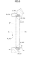
- the seal member 60 is formed into a circular shape. As illustrated in FIG. 3 , an outer circumference portion 61 of the seal member 60 is fixed to an opening edge portion 22 of the guide bush-supporting base 20 forming the through-hole 21. An inner circumference portion 62 of the seal member 60 obliquely extends toward the front F and the axis C which is the center of the through-hole 21, and has a lip (hereinafter, referred to as a lip 62) whose thickness is reduced as it approaches closer to the leading end.
- a lip 62 whose thickness is reduced as it approaches closer to the leading end.
- the inner diameter of the leading end of the lip 62 is set smaller than the outer diameter of an outer circumference surface 12a of the main spindle cover 12 in a state in which the seal member 60 is fixed to the guide bush-supporting base 20.
- the lip 62 of the seal member 60 does not have contact with the outer circumference surface 12a of the main spindle cover 12 in a position in a direction along the axis C.
- the lip 62 extends toward the front F, so that the turnings, cutting oil, or the like adhered to a part of the outer circumference surface 12a of the main spindle cover 12 in the front F of the lip 62 are removed by the leading end of the lip 62 when the main spindle 11 returns to the position of the rear R.
- the outer circumference surface 12a of the main spindle cover 12 returned to the position of the rear R is prevented from being adhered by the turnings, cutting oil, or the like.
- the main spindle cover 12 when the rotary guide bush device 30 is attached to the guide bush-supporting base 20 may differ from the main spindle cover 12 when the rotary guide bush device 30 is removed from the guide bush-supporting base 20.
- the main spindle cover 12 in which the outer circumference surface 12a has contact with the lip 62 of the seal member 60 from the outside when the rotary guide bush device 30 is removed from the guide bush-supporting base 20 may be used.
- the lip 62 of the seal member 60 has contact with the outer circumference surface 35a of the guide bush holder 35.
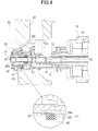
- the inner diameter of the lip 62 is set larger than the outer diameter of the outer circumference surface 35a of the guide bush holder 35, such that the lip 62 of the seal member 60 does not have contact with the outer circumference surface 35a of the guide bush holder 35, as illustrated in FIG. 4 when the main spindle 11 is located in the position of the rear R of the rotary guide bush device 30.
- the lip 62 of the seal member 60 does not have contact with the outer circumference surface 35a of the guide bush holder 35, so that the acceleration of the wear of the seal member 60 is prevented.
- main spindle cover 12 can be removed in this case.
- the processing machine of the present embodiment is a machine in which the guide bush 31 of the rotary guide bush device 30 is applied as a guide bush.
- the processing machine according to the present invention is not limited to the processing machine using the guide bush of the rotary guide bush device, and may be a machine using a guide bush of a fixed guide bush device.
- the main portion of the processing machine of Embodiment 2 includes a main spindle 111 which holds the workpiece 200, and rotates about an axis C, and a fixed guide bush device 130 (refer to FIG. 5 ) or a rotary guide bush device 230 (refer to FIG. 6 ) supported in a removable manner by a guide bush-supporting base 120 (supporting base) provided in the front F along the axis C direction of the main spindle 111.
- a tool 150 which processes the workpiece 200 is disposed in the front F just proximal to the fixed guide bush device 130 or the rotary guide bush device 230.
- the tool 150 is fixed to a not-shown tool post which is movable in one to three directions, and performs desired processing on a part of the workpiece 200 projecting to the front F from the fixed guide bush device 130 or the rotary guide bush device 230 while moving in a movable direction.
- the main spindle 111 is supported by a main spindle base 113 to be drivable and rotatable about the axis C, the outer circumference surface of the leading end portion of the main spindle 111 is covered from the outside by main spindle covers 114, 115, 116 fixed to the main spindle base 113, and the main spindle 111 rotates and is driven by a built-in motor 170.
- the main spindle covers 114, 115, 116 are formed such that the outer diameter of the main spindle cover 116 corresponding to the rear side portion is thicker than the outer diameters of the main spindle covers 114, 115 corresponding to the front side portion along the axis C direction.
- the fixed guide bush device 130 and the rotary guide bush device 230 are fixed to the guide bush-supporting base 120 through guide bush holders 135, 235, respectively, and can be removed from the guide bush-supporting base 120 together with the guide bush holders 135, 235.
- the rotary guide bush device 230 includes a bearing, a guide bush sleeve, a guide bush 231, and a draw bar connected to the guide bush 231 to change a diameter of the guide bush 231 by rotating about the axis C.
- the outside of the bearing is held in the guide bush holder 235, and the sleeve disposed inside the bearing, the guide bush 231, and the draw bar are rotatable about the axis C relative to the guide bush holder 235 in synchronization with the main spindle 111.
- the workpiece 200 held in the rotary guide bush 230 is rotatable about the axis C and movable along the axis C direction in the guide bush 231.
- a sprocket is integrally attached to the guide bush sleeve, and the guide bush 231 rotates about the axis C together with the guide bush sleeve by a belt wound around the sprocket.
- the driving of the belt is synchronized with the rotation of the main spindle 111.
- the fixed guide bush device 130 includes a guide bush 131 and a draw bar connected to the guide bush 131 to change the diameter of the guide bush 131 by rotating about the axis C.
- the outside of the guide bush 131 is held in the guide bush holder 135.
- the workpiece 200 held in the fixed guide bush device 130 is rotatable about the axis C and movable along the axis C direction in the guide bush 131.
- the main spindle 110 is disposed in the position of the rear R of the fixed guide bush device 130 or the rotary guide bush device 230 along the axis C direction when the fixed guide bush device 130 or the rotary guide bush device 230 is attached to the guide bush-supporting base 120, as illustrated in FIGS. 5 , 6 .
- the main spindle 111 is moved to the region of the fixed guide bush device 130 or the rotary guide bush device 230 where the fixed guide bush device 130 or the rotary guide bush device 230 has been attached to be disposed in the position of the front F along the axis C direction when the fixed guide bush device 130 and the rotary guide bush device 230 are removed from the guide bush-supporting base 120, as illustrated in FIGS. 7 , 8 .
- the processing machine can alternately select processing with the fixed guide bush device 130, processing with the rotary guide bush device 230, and processing without the fixed guide bush device 130 and the rotary guide bush device 230 according to a processing type or the like to be performed on the workpiece 200.
- a tubular attachment member 125 is provided in a part of the guide bush-supporting base 120 opposite to a part of the front F of the main spindle 111.
- An end portion 125a of the attachment member 125 in the front F is located adjacent to or has contact with the guide bush holder 135, 235 attached to the guide bush-supporting base 120, and seals an inside space R1 and an outside space R2 divided by the attachment member 125.
- the inside space R1 is a space in which the main spindle 111 is disposed.
- a part of the attachment member 125 in the rear R along the axis C direction is provided with the seal member 160 over the entire circumference of the inner circumference surface of the attachment member 125.
- the main spindle covers 114, 115 which are front thin diameter portions along the axis C direction, and the main spindle cover 116, which is a rear thick diameter portion having an external diameter thicker than the thin diameter potions, are formed.
- the seal member 160 is disposed outside the thin diameter portion of the main spindle covers 114, 115, 116 when the fixed guide bush device 130 or the rotary guide bush device 230 is attached to the guide bush-supporting base 120, and is disposed outside the thick diameter portion when the fixed guide bush device 130 and the rotary guide bush device 230 are removed from the guide bush-supporting base 120.
- the seal member 160 is formed in a circular shape similar to the seal member 60 in Embodiment 1.
- An outer circumference portion 161 of the seal member 160 is fixed to an inner circumference surface 125b of the attachment member 125, and an inner circumference portion 162 of the seal member 160 obliquely extends toward the front F and the axis C which is the center of the main spindle 111, and has a lip whose thickness is reduced as it approaches closer to the leading end (hereinafter, referred to as a lip 162).
- the inner diameter of the leading end of the lip 162 is smaller than the outer diameter of the outer circumference surface 116a of the main spindle cover 116, which is a thick diameter portion, and is set larger than the outer diameter of the outer circumference surfaces 114a, 115a of the main spindle covers 114, 115, which are thin diameter portions.
- the outer circumference surfaces 114a, 115a of the main spindle covers 114, 115 are set such that the leading end of the lip 162 is located in the stroke range of the main spindle 111 when the workpiece 200 is processed by using the fixed guide bush device 130 or the rotary guide bush device 230, namely, the stroke range of the main spindle covers 114, 115 corresponding to the range between the front end position and the last end position of the main spindle 111 in processing.
- the lip 162 of the seal member 160 does not have contact with the outer circumference surfaces 114a, 115a of the main spindle covers 114, 115 from the outside, so that the processing can be performed without the contact between the seal member 160 (lip 162) and the outer circumference surfaces 114a, 115a of the main spindle covers 114, 115.
- the lip 62 extends toward the front F, the turnings, cutting oil, or the like adhered to a part of the outer circumference surface 116a of the main spindle cover 116 in the front F of the lip 162 are removed by the leading end of the lip 162 when the main spindle 111 returns to the position of the rear R. Therefore, the turnings, cutting oil, or the like are prevented from being adhered to the outer circumferential surface 116a of the main spindle cover 116 returned to the position of the rear R.
- FIG. 7 illustrates a state in which the main spindle 111 is disposed in the last end position of the movable range of the main spindle 111 when the workpiece 200 is processed without using the fixed guide bush device 130 or the rotary guide bush device 230.
- FIG. 8 illustrates a state in which the main spindle 111 is disposed in the front end position of the movable range of the main spindle 111.
- the lip 162 of the seal member 160 is maintained in a state which has contact with the outer circumference surface 116a of the main spindle cover 116 from the outside over the entire region of the movable range of the main spindle 111, and the processing can be performed in a state in which the seal member 160 (lip 162) has contact with the outer circumference surface 116a of the main spindle cover 116.
- the oil or the like can be therefore prevented from being adhered to a sprocket or a belt which is disposed in the outside space R2 to rotate the rotary guide bush 230 about the axis C.
- a labyrinth seal ( FIG. 6 ) is provided between the end portion 125a of the attachment member 125 in the front F and the guide bush holder 235.
- another type of a seal member may be provided between the end portion 125a and the guide bush holder 235.
- the portion in which the thickness of the outer circumference surfaces 114a, 115a of the main spindle covers 114, 115 and the thickness of the outer circumference surface 116a of the main spindle cover 116 are changed is formed by a step whose thickness is sharply changed, but such a thickness-changing portion may be formed by a taper whose thickness is gradually changed.
- the turnings, cutting oil, or the like can be prevented from entering in the rear R of the main spindle 10, 110 by the seal member 60, 160 in a state in which the rotary guide bush device 30, 230 is removed from the guide bush-supporting base 20, 120.
- the turnings, cutting oil, or the like may blow in a part of the main spindle 11, 111 in the front F of the seal member 60, 160.
- the portion where the pulley and the belt are disposed is covered by a cover for shielding from the turnings, cutting oil, or the like.
- Embodiments 1, 2 illustrate the processing device provided with the main spindle covers 12, 114, 115, 116 which cover the main spindle 11, 111 from the outside of the outer circumference surface of the main spindle 11, 111. Therefore, in the processing without using the guide bush device 30, 130, 230, the seal member 60, 160 has contact with the outer circumference surface 12a, 116a of the main spindle cover 12, 116 for sealing. However, different from such a processing machine, in a processing machine in which an outer circumference surface of a main spindle is exposed without providing the main spindle cover, a seal member has contact with the outer circumference surface of the main spindle for sealing in processing without using the guide bush device 30, 130, 230.
- a seal member which seals the outer circumference surface of the main spindle can be a seal member which seals the outer circumference surface of the main spindle cover.
- the processing machine includes the main spindle covers 12, 114, 115, 116 which cover the outer circumference surface of the main spindle 11, 111 from the outside.
- the outer circumference surface of the main spindle cover 12, 114, 115, 116 corresponds to the outer circumference surface on the main spindle side in the processing machine according to the present invention.
- the outer circumference surface of the main spindle 11, 111 corresponds to the outer circumference surface on the main spindle side in the processing machine according to the present invention.
- the seal member 60, 160 has contact with the outer circumference surface 12a, 116a of the main spindle cover 12, 116 over the entire circumference.
- the sealing is performed between the seal member 60, 160 and the outer circumference surface 12a, 116 of the main spindle cover 12, 116, it is substantially equal to the contact between the seal member 60, 160 and outer circumference surface 12a, 116a of the main spindle cover 12, 116 even when a small space is formed between the seal member 60, 160 and the outer circumference surface 12a, 116a of the main spindle cover 12, 116.
- the seal member 60, 160 has contact with the outer circumference surface 12a, 116a of the main spindle cover 12, 116 over the entire circumference.
Landscapes
- Engineering & Computer Science (AREA)
- Mechanical Engineering (AREA)
- Turning (AREA)
- Auxiliary Devices For Machine Tools (AREA)
- Centrifugal Separators (AREA)
- Housings And Mounting Of Transformers (AREA)
- Sealing Devices (AREA)
- Machine Tool Units (AREA)
Abstract
Description
- The present invention relates to a processing machine, in particular, to an improvement in a processing machine including a guide bush.
- In a conventional processing machine such as a lathe, a processing target (hereinafter, referred to as a workpiece) is fixed to a main spindle, and a part of the workpiece projecting from the leading end of the main spindle is processed by a tool while rotating the workpiece by rotating the main spindle about an axis.
- Some processing machines include a guide bush which supports a workpiece just proximal to a processing tool between a leading end of a main spindle and the processing tool.
- Such a guide bush is attached to a guide bush-supporting base fixed ahead of the leading end of the main spindle, and the workpiece is supported to be rotatable about an axis and movable in an axis direction.
- It may be desired to perform processing without using a guide bush depending on a processing type and/or a condition of a workpiece even though the processing machine includes the guide bush.
- A processing machine is therefore proposed in which a guide bush is removed from a guide bush-supporting base according to a condition to enable processing without using the guide bush (Patent Literature 1).
- In this processing machine, a guide bush attachment hole for attaching a guide bush is formed in a guide bush-supporting base formed to be orthogonal to an axis direction of a main spindle, and the main spindle supporting the workpiece moves forward to the guide bush attachment hole to process the workpiece in a state in which the guide bush is removed from the guide bush-supporting base.
- Patent Literature 1:
JP3359808B - In the processing machine described in Patent Literature 1, when the guide bush is removed, a cover member is attached to a region where the guide bush has been attached.
- The cover member is for filling a space between the guide bush attachment hole and an outer circumference of a main spindle moved therein. By filling the space, turnings, oil, or the like generated by processing with a processing tool can be prevented from entering in the back side of the main spindle.
- However, unfortunately, such a processing machine requires a complicated process of attaching and removing the cover member in each case of attaching and removing the guide bush.
- The present invention has been made in view of the above circumstances, and an object of the present invention is to provide a processing machine which enables selection of processing with or without a guide bush, and simplifies a complicated process required for switching the processing with or without the guide bush.
- A processing machine according to the present invention includes a guide bush supported in a removable manner by a supporting base provided in a front along an axis direction of a main spindle, wherein the main spindle is disposed in a position of a rear of the guide bush along the axis direction when the guide bush is attached to the supporting base, and the main spindle is moved to a region of the guide bush where the guide bush has been attached to be disposed in a position of the front along the axis direction when the guide bush is removed from the supporting base, and the supporting base is fixedly provided with a seal member which has contact with an outer circumference surface on the main spindle side over an entire circumference when the main spindle is disposed in the position of the front.
- In addition, the outer circumference surface on the main spindle side represents the outer circumference surface of the main spindle cover in a processing machine provided with the main spindle cover which covers an outer circumference surface of a main spindle base by which the main spindle is supported and/or the outer circumference surface of the main spindle from the outside, and also represents the outer circumference surface of the main spindle in a processing machine in which the outer circumference surface of the main spindle is exposed without having the main spindle cover.
- According to the processing machine of the present invention, processing with or without a guide bush can be selected, and a complicated process required for switching the processing with or without the guide bush can be simplified.
-
-
FIG. 1 is a sectional view illustrating a main portion of a processing machine according to Embodiment 1 of the present invention in a state in which a guide bush device is attached. -
FIG. 2 is a sectional view illustrating the main portion of the processing machine illustrated inFIG. 1 in a state in which the guide bush device is removed. -
FIG. 3 is a sectional view illustrating details of a seal member. -
FIG. 4 is a sectional view illustrating a main portion according to a modified example of Embodiment 1. -
FIG. 5 is a sectional view illustrating a main portion of a processing machine according to Embodiment 2 of the present invention in a state in which a fixed guide bush device is attached. -
FIG. 6 is a sectional view illustrating the main portion of the processing machine illustrated inFIG. 5 in a state in which a rotary guide bush device is attached instead of the fixed guide bush device. -
FIG. 7 is a sectional view illustrating the main portion of the processing machine illustrated inFIGS. 5 ,6 in a state in which the guide bush device is removed (main spindle is located in the last end). -
FIG. 8 is a sectional view illustrating the main portion of the processing machine illustrated inFIGS. 5 ,6 in a state in which the guide bush device is removed (main spindle is located in the front end). - Hereinafter, embodiments of a processing machine according to the present invention will be described with reference to the drawings.
- As illustrated in
FIG. 1 , the main portion of the processing machine of Embodiment 1 includes amain spindle 11 which maintains aworkpiece 200, and rotates about an axis C and a rotaryguide bush device 30 supported in a removable manner by a guide bush-supporting base 20 (supporting base) provided in a front F along an axis C direction of themain spindle 11. Atool 50 which processes theworkpiece 200 is disposed in the front F just proximal to the rotaryguide bush device 30. - As is known in the art, the
tool 50 is fixed to atool post 40 which is movable in one to three directions, and performs desired processing on a part of theworkpiece 200 projecting to the front F from the rotaryguide bush device 30 while moving in a movable direction. - The
main spindle 11 is supported by amain spindle base 13 to be drivable and rotatable about the axis C, an outer circumference surface of the leading end portion of themain spindle 11 is covered from the outside by amain spindle cover 12 fixed to themain spindle base 13, and themain spindle 11 rotates and is driven by a built-inmotor 70. - The rotary
guide bush device 30 is fixed to the guide bush-supportingbase 20 through aguide bush holder 35, and the rotaryguide bush device 30 can be removed from the guide bush-supportingbase 20 together with theguide bush holder 35. - The rotary
guide bush device 30 includes a bearing, a guide bush sleeve, aguide bush 31, and a draw bar connected to theguide bush 31 to change a diameter of theguide bush 31 by rotating about the axis C. An outside of the bearing is held in theguide bush holder 35, and the sleeve disposed inside the bearing, theguide bush 31, and the draw bar are rotatable about the axis C relative to theguide bush holder 35 in synchronization with themain spindle 11. - The
workpiece 200 held in the rotaryguide bush device 30 is rotatable about the axis C and movable along the axis C direction in theguide bush 31. - A sprocket is integrally attached to a chuck sleeve, the
guide bush 31 rotates about the axis C together with the chuck sleeve by a belt wound around the sprocket, and this driving of the belt is synchronized with the rotation of themain spindle 11. - The
main spindle 11 is disposed in a position of a rear R of the rotaryguide bush device 30 along the axis C direction when the rotaryguide bush device 30 is attached to the guide bush-supportingbase 20, as illustrated inFIG. 1 . Themain spindle 11 is moved to the region of the rotaryguide bush device 30 where the rotaryguide bush device 30 has been attached to be disposed in a position of the front F along the axis C direction when the rotaryguide bush device 30 is removed from the guide bush-supportingbase 20, as illustrated inFIG. 2 . - The processing device can alternately select processing with the rotary
guide bush device 30 and processing without the rotaryguide bush device 30 according to a processing type or the like to be performed on theworkpiece 200. - In this case, a
through hole 21 of the guide bush-supportingbase 20 in which the rotaryguide bush device 30 is disposed is provided with aseal member 60 over the entire circumference of the through-hole 21. Namely, theseal member 60 is provided outside theguide bush holder 35 in the diameter direction in a region of a length from the rotaryguide bush device 30 to theguide bush holder 35 in a state in which the rotaryguide bush device 30 is attached to the guide bush-supportingbase 20. - The
seal member 60 is formed into a circular shape. As illustrated inFIG. 3 , an outer circumference portion 61 of theseal member 60 is fixed to anopening edge portion 22 of the guide bush-supportingbase 20 forming the through-hole 21. Aninner circumference portion 62 of theseal member 60 obliquely extends toward the front F and the axis C which is the center of the through-hole 21, and has a lip (hereinafter, referred to as a lip 62) whose thickness is reduced as it approaches closer to the leading end. - The inner diameter of the leading end of the
lip 62 is set smaller than the outer diameter of anouter circumference surface 12a of themain spindle cover 12 in a state in which theseal member 60 is fixed to the guide bush-supportingbase 20. - As illustrated in
FIG. 1 , when the rotaryguide bush device 30 is attached to the guide bush-supportingbase 20, and themain spindle 11 is located in the position of the rear R of the rotaryguide bush device 30, thelip 62 of theseal member 60 does not have contact with theouter circumference surface 12a of themain spindle cover 12 in a position in a direction along the axis C. - On the other hand, when the rotary
guide bush device 30 is removed from the guide bush-supportingbase 20, and themain spindle 11 is disposed in the position of the front F, as illustrated inFIG. 2 , thelip 62 of theseal member 60 has contact with theouter circumference surface 12a of themain spindle cover 12 from the outside over the entire circumference. - With this configuration, even when turnings, cutting oil, or the like in the processing of the
workpiece 200 with thetool 50 fly from the front F to the rear R along the axis C direction of themain spindle 11, these are blocked by theseal member 60 which seals the space between the guide bush-supportingbase 20 and themain spindle cover 12. Thus, the turnings, cutting oil, or the like are prevented from entering in the rear R of the portion with which theseal member 60 has contact. - Moreover, the
lip 62 extends toward the front F, so that the turnings, cutting oil, or the like adhered to a part of theouter circumference surface 12a of themain spindle cover 12 in the front F of thelip 62 are removed by the leading end of thelip 62 when themain spindle 11 returns to the position of the rear R. Thus, theouter circumference surface 12a of themain spindle cover 12 returned to the position of the rear R is prevented from being adhered by the turnings, cutting oil, or the like. - The
main spindle cover 12 when the rotaryguide bush device 30 is attached to the guide bush-supportingbase 20 may differ from themain spindle cover 12 when the rotaryguide bush device 30 is removed from the guide bush-supportingbase 20. Themain spindle cover 12 in which theouter circumference surface 12a has contact with thelip 62 of theseal member 60 from the outside when the rotaryguide bush device 30 is removed from the guide bush-supportingbase 20 may be used. - On the other hand, when the rotary
guide bush device 30 is attached to the guide bush-supportingbase 20 by theguide bush holder 35, there is a no space between theguide bush holder 35 and the guide bush-supportingbase 20. The turnings, cutting oil, or the like therefore do not enter in the rear R of the rotaryguide bush device 30. - Namely, it is not necessary to seal between the
guide bush holder 35 and the guide bush-supportingbase 20 because thelip 62 of theseal member 60 has contact with theouter circumference surface 35a of theguide bush holder 35. - Referring to
FIG. 1 , in a state in which theguide bush device 30 is attached to the guide bush-supportingbase 20, thelip 62 of theseal member 60 has contact with theouter circumference surface 35a of theguide bush holder 35. However, the inner diameter of thelip 62 is set larger than the outer diameter of theouter circumference surface 35a of theguide bush holder 35, such that thelip 62 of theseal member 60 does not have contact with theouter circumference surface 35a of theguide bush holder 35, as illustrated inFIG. 4 when themain spindle 11 is located in the position of the rear R of the rotaryguide bush device 30. - In this case, the
lip 62 of theseal member 60 does not have contact with theouter circumference surface 35a of theguide bush holder 35, so that the acceleration of the wear of theseal member 60 is prevented. - Moreover, the
main spindle cover 12 can be removed in this case. - In addition, the processing machine of the present embodiment is a machine in which the
guide bush 31 of the rotaryguide bush device 30 is applied as a guide bush. However, the processing machine according to the present invention is not limited to the processing machine using the guide bush of the rotary guide bush device, and may be a machine using a guide bush of a fixed guide bush device. - As illustrated in
FIGS. 5 ,6 ,7 ,8 , the main portion of the processing machine of Embodiment 2 includes amain spindle 111 which holds theworkpiece 200, and rotates about an axis C, and a fixed guide bush device 130 (refer toFIG. 5 ) or a rotary guide bush device 230 (refer toFIG. 6 ) supported in a removable manner by a guide bush-supporting base 120 (supporting base) provided in the front F along the axis C direction of themain spindle 111. Atool 150 which processes theworkpiece 200 is disposed in the front F just proximal to the fixedguide bush device 130 or the rotaryguide bush device 230. - As is known in the art, the
tool 150 is fixed to a not-shown tool post which is movable in one to three directions, and performs desired processing on a part of theworkpiece 200 projecting to the front F from the fixedguide bush device 130 or the rotaryguide bush device 230 while moving in a movable direction. - The
main spindle 111 is supported by amain spindle base 113 to be drivable and rotatable about the axis C, the outer circumference surface of the leading end portion of themain spindle 111 is covered from the outside by main spindle covers 114, 115, 116 fixed to themain spindle base 113, and themain spindle 111 rotates and is driven by a built-inmotor 170. - In this case, the main spindle covers 114, 115, 116 are formed such that the outer diameter of the
main spindle cover 116 corresponding to the rear side portion is thicker than the outer diameters of the main spindle covers 114, 115 corresponding to the front side portion along the axis C direction. - The fixed
guide bush device 130 and the rotaryguide bush device 230 are fixed to the guide bush-supportingbase 120 throughguide bush holders base 120 together with theguide bush holders - The rotary
guide bush device 230 includes a bearing, a guide bush sleeve, aguide bush 231, and a draw bar connected to theguide bush 231 to change a diameter of theguide bush 231 by rotating about the axis C. The outside of the bearing is held in theguide bush holder 235, and the sleeve disposed inside the bearing, theguide bush 231, and the draw bar are rotatable about the axis C relative to theguide bush holder 235 in synchronization with themain spindle 111. - The
workpiece 200 held in therotary guide bush 230 is rotatable about the axis C and movable along the axis C direction in theguide bush 231. - A sprocket is integrally attached to the guide bush sleeve, and the
guide bush 231 rotates about the axis C together with the guide bush sleeve by a belt wound around the sprocket. The driving of the belt is synchronized with the rotation of themain spindle 111. - On the other hand, the fixed
guide bush device 130 includes aguide bush 131 and a draw bar connected to theguide bush 131 to change the diameter of theguide bush 131 by rotating about the axis C. The outside of theguide bush 131 is held in theguide bush holder 135. - The
workpiece 200 held in the fixedguide bush device 130 is rotatable about the axis C and movable along the axis C direction in theguide bush 131. - The main spindle 110 is disposed in the position of the rear R of the fixed
guide bush device 130 or the rotaryguide bush device 230 along the axis C direction when the fixedguide bush device 130 or the rotaryguide bush device 230 is attached to the guide bush-supportingbase 120, as illustrated inFIGS. 5 ,6 . Themain spindle 111 is moved to the region of the fixedguide bush device 130 or the rotaryguide bush device 230 where the fixedguide bush device 130 or the rotaryguide bush device 230 has been attached to be disposed in the position of the front F along the axis C direction when the fixedguide bush device 130 and the rotaryguide bush device 230 are removed from the guide bush-supportingbase 120, as illustrated inFIGS. 7 ,8 . - The processing machine can alternately select processing with the fixed
guide bush device 130, processing with the rotaryguide bush device 230, and processing without the fixedguide bush device 130 and the rotaryguide bush device 230 according to a processing type or the like to be performed on theworkpiece 200. - In this case, a
tubular attachment member 125 is provided in a part of the guide bush-supportingbase 120 opposite to a part of the front F of themain spindle 111. Anend portion 125a of theattachment member 125 in the front F is located adjacent to or has contact with theguide bush holder base 120, and seals an inside space R1 and an outside space R2 divided by theattachment member 125. - In addition, the inside space R1 is a space in which the
main spindle 111 is disposed. - A part of the
attachment member 125 in the rear R along the axis C direction is provided with theseal member 160 over the entire circumference of the inner circumference surface of theattachment member 125. - The main spindle covers 114, 115, which are front thin diameter portions along the axis C direction, and the
main spindle cover 116, which is a rear thick diameter portion having an external diameter thicker than the thin diameter potions, are formed. - The
seal member 160 is disposed outside the thin diameter portion of the main spindle covers 114, 115, 116 when the fixedguide bush device 130 or the rotaryguide bush device 230 is attached to the guide bush-supportingbase 120, and is disposed outside the thick diameter portion when the fixedguide bush device 130 and the rotaryguide bush device 230 are removed from the guide bush-supportingbase 120. - As illustrated in
FIG. 3 , theseal member 160 is formed in a circular shape similar to theseal member 60 in Embodiment 1. An outer circumference portion 161 of theseal member 160 is fixed to an inner circumference surface 125b of theattachment member 125, and aninner circumference portion 162 of theseal member 160 obliquely extends toward the front F and the axis C which is the center of themain spindle 111, and has a lip whose thickness is reduced as it approaches closer to the leading end (hereinafter, referred to as a lip 162). - In a state in which the
seal member 160 is fixed to theattachment member 125, the inner diameter of the leading end of thelip 162 is smaller than the outer diameter of theouter circumference surface 116a of themain spindle cover 116, which is a thick diameter portion, and is set larger than the outer diameter of theouter circumference surfaces - The
outer circumference surfaces lip 162 is located in the stroke range of themain spindle 111 when theworkpiece 200 is processed by using the fixedguide bush device 130 or the rotaryguide bush device 230, namely, the stroke range of the main spindle covers 114, 115 corresponding to the range between the front end position and the last end position of themain spindle 111 in processing. - As illustrated in
FIGS. 5 ,6 , when the fixedguide bush device 130 or the rotaryguide bush device 230 is attached to the guide bush-supportingbase 120, and themain spindle 111 is located in the position of the rear R, thelip 162 of theseal member 160 does not have contact with theouter circumference surfaces outer circumference surfaces - On the other hand, when the fixed
guide bush device 130 and the rotaryguide bush device 230 are removed from the guide bush-supportingbase 120, and themain spindle 111 is disposed in the position of the front F, as illustrated inFIG. 7 , thelip 162 of theseal member 160 has contact with theouter circumference surface 116a of themain spindle cover 116 from the outside over the entire circumference. - With this configuration, even when turnings, cutting oil, or the like in the processing of the
workpiece 200 with thetool 150 fly from the front F to the rear R along the axis C direction of themain spindle 111, these are blocked by theseal member 160 sealing the space between theattachment member 125 of the guide bush-supportingbase 120 and themain spindle cover 116. Thus, the turning, cutting oil, or the like are prevented from entering in the rear R of the portion with which theseal member 160 has contact. - Moreover, since the
lip 62 extends toward the front F, the turnings, cutting oil, or the like adhered to a part of theouter circumference surface 116a of themain spindle cover 116 in the front F of thelip 162 are removed by the leading end of thelip 162 when themain spindle 111 returns to the position of the rear R. Therefore, the turnings, cutting oil, or the like are prevented from being adhered to the outercircumferential surface 116a of themain spindle cover 116 returned to the position of the rear R. - In addition,
FIG. 7 illustrates a state in which themain spindle 111 is disposed in the last end position of the movable range of themain spindle 111 when theworkpiece 200 is processed without using the fixedguide bush device 130 or the rotaryguide bush device 230. On the other hand,FIG. 8 illustrates a state in which themain spindle 111 is disposed in the front end position of the movable range of themain spindle 111. - The
lip 162 of theseal member 160 is maintained in a state which has contact with theouter circumference surface 116a of themain spindle cover 116 from the outside over the entire region of the movable range of themain spindle 111, and the processing can be performed in a state in which the seal member 160 (lip 162) has contact with theouter circumference surface 116a of themain spindle cover 116. - On the other hand, when the fixed
guide bush device 130 or the rotaryguide bush device 230 is attached to the guide bush-supportingbase 120, there is no space between theguide bush holder base 120. Thus, the turnings, cutting oil, or the like do not enter into the rear R of the fixedguide bush device 130 and the rotaryguide bush device 230. - More specifically, it is not necessary for the
lip 162 of theseal member 160 to seal between theguide bush holder base 120 by the contact with any of the members. The acceleration of the wear of theseal member 160 can be thus prevented. - However, in any of the above-described cases, a tiny amount of oil or the like may enter into the inside space R1 divided by the
attachment member 125 from the inner diameter side of the guide bush. This amount of oil entering is not a problem for the leakage to the rear R of themain spindle attachment member 125, it becomes a problem for the driving side of the rotaryguide bush device 230 when the rotaryguide bush device 230 is attached. - On the other hand, by forming a sealing structure between the
end portion 125a of theattachment member 125 in the front F and theguide bush holder 235, the oil or the like entering in the inside space R1 is prevented from entering into the outside space R2. - The oil or the like can be therefore prevented from being adhered to a sprocket or a belt which is disposed in the outside space R2 to rotate the
rotary guide bush 230 about the axis C. - In the present embodiment, a labyrinth seal (
FIG. 6 ) is provided between theend portion 125a of theattachment member 125 in the front F and theguide bush holder 235. In addition, another type of a seal member may be provided between theend portion 125a and theguide bush holder 235. - In the processing machine according to Embodiment 2, the portion in which the thickness of the
outer circumference surfaces outer circumference surface 116a of themain spindle cover 116 are changed is formed by a step whose thickness is sharply changed, but such a thickness-changing portion may be formed by a taper whose thickness is gradually changed. - In each of the above-described Embodiments 1, 2 and the modified example, in the machines using the rotary
guide bush devices seal member guide bush device base main spindle seal member - In this case, when a driving side pulley and belt driving the rotary
guide bush device seal member - In the above-described configuration, it is preferable for the portion where the pulley and the belt are disposed to be covered by a cover for shielding from the turnings, cutting oil, or the like.
- In addition, the above-described Embodiments 1, 2 illustrate the processing device provided with the main spindle covers 12, 114, 115, 116 which cover the
main spindle main spindle guide bush device seal member outer circumference surface main spindle cover guide bush device - The processing machine according to the above-described embodiments includes the main spindle covers 12, 114, 115, 116 which cover the outer circumference surface of the
main spindle main spindle cover main spindle - In the processing machine according to the above-described embodiments, the
seal member outer circumference surface main spindle cover seal member outer circumference surface main spindle cover seal member outer circumference surface main spindle cover seal member outer circumference surface main spindle cover seal member outer circumference surface main spindle cover - The present application is based on and claims priority from Japanese Patent Application No.
2012-079332, filed on March 30, 2012 -
- 11, 111
- main spindle
- 12, 114, 115, 116
- main spindle cover
- 12a, 114a, 115a, 116a
- outer circumference surface
- 13, 113
- main spindle base
- 20, 120
- guide bush-supporting base
- 21
- through-hole
- 22
- opening edge portion
- 30, 230
- rotary guide bush device
- 31, 131, 231
- guide bush
- 35, 135, 235
- guide bush holder
- 35a
- outer circumference surface
- 40
- tool post
- 50, 150
- tool
- 60, 160
- seal member
- 61, 161
- outer circumference portion
- 62, 162
- inner circumference portion, lip
- 70, 170
- built-in motor
- 130
- fixed guide bush device
- 200
- workpiece (processing target)
- C
- axis
- F
- front
- R
- rear
Claims (5)
- A processing machine comprising a guide bush supported in a removable manner by a supporting base provided in a front along an axis direction of a main spindle, wherein
the main spindle is disposed in a position of a rear of the guide bush along the axis direction when the guide bush is attached to the supporting base, and the main spindle is moved to a region of the guide bush where the guide bush has been attached to be disposed in a position of the front along the axis direction when the guide bush is removed from the supporting base, and
the supporting base is fixedly provided with a seal member which has contact with an outer circumference surface on the main spindle side over an entire circumference when the main spindle is disposed in the position of the front. - The processing machine according to Claim 1, wherein the seal member is disposed outside an outer circumference surface of the guide bush when the guide bush is attached to the supporting base, and
an inner diameter of the seal member is formed smaller than an outer diameter of the main spindle cover. - The processing machine according to Claim 2, wherein the inner diameter of the seal member is formed larger than an outer diameter of the guide bush.
- The processing machine according to Claim 1, wherein the main spindle side includes a front thin diameter portion along the axis direction and a rear thick diameter portion having an outer diameter larger than the thin diameter portion, and
the seal member is located outside the thin diameter portion when the guide bush is attached to the supporting base, the seal member is located outside the thick diameter portion when the guide bush is removed from the supporting base, and an inner diameter of the seal member is formed smaller than an outer diameter of the thick diameter portion. - The processing machine according to Claim 4, wherein the inner diameter of the seal member is formed larger than an outer diameter of the thin diameter portion.
Applications Claiming Priority (2)
| Application Number | Priority Date | Filing Date | Title |
|---|---|---|---|
| JP2012079332 | 2012-03-30 | ||
| PCT/JP2013/059033 WO2013146898A1 (en) | 2012-03-30 | 2013-03-27 | Processing equipment |
Publications (3)
| Publication Number | Publication Date |
|---|---|
| EP2832476A1 true EP2832476A1 (en) | 2015-02-04 |
| EP2832476A4 EP2832476A4 (en) | 2015-12-30 |
| EP2832476B1 EP2832476B1 (en) | 2023-08-30 |
Family
ID=49260147
Family Applications (1)
| Application Number | Title | Priority Date | Filing Date |
|---|---|---|---|
| EP13769571.4A Active EP2832476B1 (en) | 2012-03-30 | 2013-03-27 | Processing equipment |
Country Status (8)
| Country | Link |
|---|---|
| US (1) | US9592556B2 (en) |
| EP (1) | EP2832476B1 (en) |
| JP (1) | JP6005728B2 (en) |
| KR (2) | KR101779753B1 (en) |
| CN (1) | CN104185525B (en) |
| ES (1) | ES2955945T3 (en) |
| TW (1) | TWI587948B (en) |
| WO (1) | WO2013146898A1 (en) |
Cited By (1)
| Publication number | Priority date | Publication date | Assignee | Title |
|---|---|---|---|---|
| US9744596B2 (en) | 2014-08-08 | 2017-08-29 | Star Micronics Co., Ltd. | Machine tool |
Families Citing this family (7)
| Publication number | Priority date | Publication date | Assignee | Title |
|---|---|---|---|---|
| EP2977130B1 (en) * | 2013-03-18 | 2019-09-25 | Citizen Watch Co., Ltd. | Guide bush control device and guide bush adjustment method |
| JP6892594B2 (en) * | 2017-03-14 | 2021-06-23 | スター精密株式会社 | Machine Tools |
| JP7464816B2 (en) * | 2019-12-20 | 2024-04-10 | スター精密株式会社 | Lathe and method for attaching guide member thereto |
| US11833630B2 (en) | 2021-05-28 | 2023-12-05 | Yamazaki Mazak Corporation | Machine tool with removable workpiece support |
| CN117881496B (en) * | 2021-08-27 | 2024-08-20 | 山崎马扎克公司 | Workpiece support device for machine tool, machine tool, and method of using machine tool |
| WO2023026477A1 (en) * | 2021-08-27 | 2023-03-02 | ヤマザキマザック株式会社 | Workpiece support device for machine tool, machine tool, and method for using machine tool |
| US12636710B2 (en) | 2022-09-09 | 2026-05-26 | Mazak Corporation | Machine tool |
Family Cites Families (23)
| Publication number | Priority date | Publication date | Assignee | Title |
|---|---|---|---|---|
| US2369330A (en) * | 1942-07-20 | 1945-02-13 | City Engineering Company | Live collet for screw machines |
| DE2537852C3 (en) * | 1975-08-26 | 1978-03-16 | Hagenuk Vormals Neufeldt & Kuhnke Gmbh, 2300 Kiel | Automatic feed device for profile bars on bar processing lathes |
| US4258598A (en) * | 1979-06-11 | 1981-03-31 | Alkron Manufacturing Corp. | Rotating guide bushing for Swiss-type automatic screw machine |
| DE3064936D1 (en) * | 1979-09-03 | 1983-10-27 | Emi Ltd | Bar feed |
| JPS62106727A (en) | 1985-11-06 | 1987-05-18 | 角 秀満 | Egg cracking machine |
| JPH0340488Y2 (en) * | 1985-12-25 | 1991-08-26 | ||
| US4997174A (en) * | 1990-01-16 | 1991-03-05 | Westinghouse Electric Corp. | Barstock locating device |
| DE4023453C1 (en) | 1990-07-24 | 1992-04-09 | Gildemeister Ag, 4800 Bielefeld, De | |
| US5615590A (en) * | 1995-07-05 | 1997-04-01 | Speckhahn; Henry D. | Guide collet adaptor for radial jaw chuck lathes |
| JP3359808B2 (en) * | 1996-02-16 | 2002-12-24 | 株式会社ツガミ | Spindle moving type lathe |
| US6446533B2 (en) * | 1999-08-20 | 2002-09-10 | Toshiharu Tom Miyano | Lathe assembly and method of using a lathe assembly |
| DE10138942A1 (en) * | 2001-08-02 | 2003-02-27 | Traub Drehmaschinen Gmbh | lathe |
| JP4455500B2 (en) * | 2003-12-26 | 2010-04-21 | シチズンホールディングス株式会社 | Automatic lathe |
| JP2006326732A (en) | 2005-05-25 | 2006-12-07 | Citizen Watch Co Ltd | Lathe |
| TWM316764U (en) * | 2007-03-15 | 2007-08-11 | Leadwell Cnc Machines Mfg Corp | Main spindle apparatus for lathe with central water outlet |
| JP4988427B2 (en) | 2007-05-10 | 2012-08-01 | スター精密株式会社 | Machine Tools |
| TWM333961U (en) * | 2007-09-06 | 2008-06-11 | Wei-Chen Chen | The spindle of CNC lathe |
| CN201103686Y (en) * | 2007-09-11 | 2008-08-20 | 大连华根机械有限公司 | Principal shaft sealing device |
| DE102008051611A1 (en) | 2008-10-07 | 2010-04-08 | Traub Drehmaschinen Gmbh & Co. Kg | lathe |
| DE102009019867A1 (en) * | 2009-05-06 | 2010-11-18 | Illinois Tool Works Inc., Glenview | Pipe processing device for machining a tubular body |
| TWM406485U (en) * | 2011-02-01 | 2011-07-01 | rong-sheng Zhang | Hidden type of main spindle |
| KR101692598B1 (en) * | 2012-03-08 | 2017-01-03 | 시티즌 도케이 가부시키가이샤 | Guide bush adjusting device |
| JP2015066648A (en) | 2013-09-30 | 2015-04-13 | シチズンホールディングス株式会社 | Machine tool |
-
2013
- 2013-03-27 EP EP13769571.4A patent/EP2832476B1/en active Active
- 2013-03-27 WO PCT/JP2013/059033 patent/WO2013146898A1/en not_active Ceased
- 2013-03-27 JP JP2014507963A patent/JP6005728B2/en active Active
- 2013-03-27 US US14/387,366 patent/US9592556B2/en active Active
- 2013-03-27 CN CN201380015750.XA patent/CN104185525B/en active Active
- 2013-03-27 KR KR1020177010641A patent/KR101779753B1/en active Active
- 2013-03-27 ES ES13769571T patent/ES2955945T3/en active Active
- 2013-03-27 KR KR1020147030418A patent/KR101759772B1/en active Active
- 2013-03-29 TW TW102111555A patent/TWI587948B/en active
Cited By (1)
| Publication number | Priority date | Publication date | Assignee | Title |
|---|---|---|---|---|
| US9744596B2 (en) | 2014-08-08 | 2017-08-29 | Star Micronics Co., Ltd. | Machine tool |
Also Published As
| Publication number | Publication date |
|---|---|
| ES2955945T3 (en) | 2023-12-11 |
| KR20170046803A (en) | 2017-05-02 |
| TW201404501A (en) | 2014-02-01 |
| CN104185525B (en) | 2016-08-24 |
| KR20140139116A (en) | 2014-12-04 |
| KR101759772B1 (en) | 2017-07-19 |
| JP6005728B2 (en) | 2016-10-12 |
| EP2832476A4 (en) | 2015-12-30 |
| EP2832476B1 (en) | 2023-08-30 |
| JPWO2013146898A1 (en) | 2015-12-14 |
| CN104185525A (en) | 2014-12-03 |
| TWI587948B (en) | 2017-06-21 |
| WO2013146898A1 (en) | 2013-10-03 |
| US9592556B2 (en) | 2017-03-14 |
| US20150090084A1 (en) | 2015-04-02 |
| KR101779753B1 (en) | 2017-09-18 |
Similar Documents
| Publication | Publication Date | Title |
|---|---|---|
| EP2832476B1 (en) | Processing equipment | |
| EP3278910A1 (en) | Tool rest for machine tool | |
| KR102266459B1 (en) | Turret Blade Holder (TURRET TOOL POST) | |
| CN106493597A (en) | Lathe | |
| US9656362B2 (en) | Tool changer equipped with covers | |
| EP1151812A4 (en) | Spinning device | |
| KR20180055873A (en) | Machining methods by machine tools and machine tools | |
| SE511542C2 (en) | Externally abrading machine | |
| US20170326702A1 (en) | Rotary table device for machine tool | |
| KR20160136121A (en) | Sub-spindle | |
| JP2015077651A (en) | Tool changer having cover | |
| JPWO2016013307A1 (en) | Machine tool, tool unit, and machining method | |
| EP3168000B1 (en) | Machine tool | |
| US20080141837A1 (en) | Rotating Tool Magazine Having an End-Mounted Rotationally Driven Tool | |
| US10792742B2 (en) | Main spindle unit and machine tool | |
| JP5608493B2 (en) | Electric machining equipment using servo motor | |
| US7395743B2 (en) | Lathe spindle unit and lathe apparatus | |
| KR101697658B1 (en) | The encoder mounted spindle motors for machine tools | |
| JP2015066648A (en) | Machine tool | |
| WO2014171244A1 (en) | Machine tool and cutting method for workpiece having protruding section | |
| TWI712461B (en) | Cutting tool for machining differential case, machining apparatus for differential case and machining method for differential case | |
| CN105782367B (en) | Two-gear planetary transmission device | |
| CN205588373U (en) | Cutting machine | |
| KR20130068278A (en) | Method for manufacturing artifact and zig for machine | |
| JP2018065193A (en) | NC lathe |
Legal Events
| Date | Code | Title | Description |
|---|---|---|---|
| PUAI | Public reference made under article 153(3) epc to a published international application that has entered the european phase |
Free format text: ORIGINAL CODE: 0009012 |
|
| 17P | Request for examination filed |
Effective date: 20141023 |
|
| AK | Designated contracting states |
Kind code of ref document: A1 Designated state(s): AL AT BE BG CH CY CZ DE DK EE ES FI FR GB GR HR HU IE IS IT LI LT LU LV MC MK MT NL NO PL PT RO RS SE SI SK SM TR |
|
| AX | Request for extension of the european patent |
Extension state: BA ME |
|
| DAX | Request for extension of the european patent (deleted) | ||
| RAP1 | Party data changed (applicant data changed or rights of an application transferred) |
Owner name: CITIZEN HOLDINGS CO., LTD. Owner name: CITIZEN MACHINERY CO., LTD. |
|
| RA4 | Supplementary search report drawn up and despatched (corrected) |
Effective date: 20151130 |
|
| RIC1 | Information provided on ipc code assigned before grant |
Ipc: B23B 7/06 20060101AFI20151124BHEP Ipc: B23B 13/12 20060101ALI20151124BHEP Ipc: B23Q 1/76 20060101ALI20151124BHEP |
|
| TPAC | Observations filed by third parties |
Free format text: ORIGINAL CODE: EPIDOSNTIPA |
|
| RAP1 | Party data changed (applicant data changed or rights of an application transferred) |
Owner name: CITIZEN MACHINERY CO., LTD. Owner name: CITIZEN WATCH CO., LTD. |
|
| STAA | Information on the status of an ep patent application or granted ep patent |
Free format text: STATUS: EXAMINATION IS IN PROGRESS |
|
| 17Q | First examination report despatched |
Effective date: 20190305 |
|
| GRAP | Despatch of communication of intention to grant a patent |
Free format text: ORIGINAL CODE: EPIDOSNIGR1 |
|
| STAA | Information on the status of an ep patent application or granted ep patent |
Free format text: STATUS: GRANT OF PATENT IS INTENDED |
|
| INTG | Intention to grant announced |
Effective date: 20230420 |
|
| GRAS | Grant fee paid |
Free format text: ORIGINAL CODE: EPIDOSNIGR3 |
|
| GRAA | (expected) grant |
Free format text: ORIGINAL CODE: 0009210 |
|
| STAA | Information on the status of an ep patent application or granted ep patent |
Free format text: STATUS: THE PATENT HAS BEEN GRANTED |
|
| AK | Designated contracting states |
Kind code of ref document: B1 Designated state(s): AL AT BE BG CH CY CZ DE DK EE ES FI FR GB GR HR HU IE IS IT LI LT LU LV MC MK MT NL NO PL PT RO RS SE SI SK SM TR |
|
| REG | Reference to a national code |
Ref country code: GB Ref legal event code: FG4D |
|
| REG | Reference to a national code |
Ref country code: CH Ref legal event code: EP |
|
| REG | Reference to a national code |
Ref country code: DE Ref legal event code: R096 Ref document number: 602013084540 Country of ref document: DE |
|
| REG | Reference to a national code |
Ref country code: IE Ref legal event code: FG4D |
|
| REG | Reference to a national code |
Ref country code: ES Ref legal event code: FG2A Ref document number: 2955945 Country of ref document: ES Kind code of ref document: T3 Effective date: 20231211 |
|
| REG | Reference to a national code |
Ref country code: LT Ref legal event code: MG9D |
|
| REG | Reference to a national code |
Ref country code: NL Ref legal event code: MP Effective date: 20230830 |
|
| REG | Reference to a national code |
Ref country code: AT Ref legal event code: MK05 Ref document number: 1604775 Country of ref document: AT Kind code of ref document: T Effective date: 20230830 |
|
| PG25 | Lapsed in a contracting state [announced via postgrant information from national office to epo] |
Ref country code: GR Free format text: LAPSE BECAUSE OF FAILURE TO SUBMIT A TRANSLATION OF THE DESCRIPTION OR TO PAY THE FEE WITHIN THE PRESCRIBED TIME-LIMIT Effective date: 20231201 |
|
| PG25 | Lapsed in a contracting state [announced via postgrant information from national office to epo] |
Ref country code: IS Free format text: LAPSE BECAUSE OF FAILURE TO SUBMIT A TRANSLATION OF THE DESCRIPTION OR TO PAY THE FEE WITHIN THE PRESCRIBED TIME-LIMIT Effective date: 20231230 |
|
| PG25 | Lapsed in a contracting state [announced via postgrant information from national office to epo] |
Ref country code: SE Free format text: LAPSE BECAUSE OF FAILURE TO SUBMIT A TRANSLATION OF THE DESCRIPTION OR TO PAY THE FEE WITHIN THE PRESCRIBED TIME-LIMIT Effective date: 20230830 Ref country code: RS Free format text: LAPSE BECAUSE OF FAILURE TO SUBMIT A TRANSLATION OF THE DESCRIPTION OR TO PAY THE FEE WITHIN THE PRESCRIBED TIME-LIMIT Effective date: 20230830 Ref country code: NO Free format text: LAPSE BECAUSE OF FAILURE TO SUBMIT A TRANSLATION OF THE DESCRIPTION OR TO PAY THE FEE WITHIN THE PRESCRIBED TIME-LIMIT Effective date: 20231130 Ref country code: LV Free format text: LAPSE BECAUSE OF FAILURE TO SUBMIT A TRANSLATION OF THE DESCRIPTION OR TO PAY THE FEE WITHIN THE PRESCRIBED TIME-LIMIT Effective date: 20230830 Ref country code: LT Free format text: LAPSE BECAUSE OF FAILURE TO SUBMIT A TRANSLATION OF THE DESCRIPTION OR TO PAY THE FEE WITHIN THE PRESCRIBED TIME-LIMIT Effective date: 20230830 Ref country code: IS Free format text: LAPSE BECAUSE OF FAILURE TO SUBMIT A TRANSLATION OF THE DESCRIPTION OR TO PAY THE FEE WITHIN THE PRESCRIBED TIME-LIMIT Effective date: 20231230 Ref country code: HR Free format text: LAPSE BECAUSE OF FAILURE TO SUBMIT A TRANSLATION OF THE DESCRIPTION OR TO PAY THE FEE WITHIN THE PRESCRIBED TIME-LIMIT Effective date: 20230830 Ref country code: GR Free format text: LAPSE BECAUSE OF FAILURE TO SUBMIT A TRANSLATION OF THE DESCRIPTION OR TO PAY THE FEE WITHIN THE PRESCRIBED TIME-LIMIT Effective date: 20231201 Ref country code: FI Free format text: LAPSE BECAUSE OF FAILURE TO SUBMIT A TRANSLATION OF THE DESCRIPTION OR TO PAY THE FEE WITHIN THE PRESCRIBED TIME-LIMIT Effective date: 20230830 Ref country code: AT Free format text: LAPSE BECAUSE OF FAILURE TO SUBMIT A TRANSLATION OF THE DESCRIPTION OR TO PAY THE FEE WITHIN THE PRESCRIBED TIME-LIMIT Effective date: 20230830 |
|
| PG25 | Lapsed in a contracting state [announced via postgrant information from national office to epo] |
Ref country code: PL Free format text: LAPSE BECAUSE OF FAILURE TO SUBMIT A TRANSLATION OF THE DESCRIPTION OR TO PAY THE FEE WITHIN THE PRESCRIBED TIME-LIMIT Effective date: 20230830 Ref country code: NL Free format text: LAPSE BECAUSE OF FAILURE TO SUBMIT A TRANSLATION OF THE DESCRIPTION OR TO PAY THE FEE WITHIN THE PRESCRIBED TIME-LIMIT Effective date: 20230830 |
|
| PG25 | Lapsed in a contracting state [announced via postgrant information from national office to epo] |
Ref country code: SM Free format text: LAPSE BECAUSE OF FAILURE TO SUBMIT A TRANSLATION OF THE DESCRIPTION OR TO PAY THE FEE WITHIN THE PRESCRIBED TIME-LIMIT Effective date: 20230830 Ref country code: RO Free format text: LAPSE BECAUSE OF FAILURE TO SUBMIT A TRANSLATION OF THE DESCRIPTION OR TO PAY THE FEE WITHIN THE PRESCRIBED TIME-LIMIT Effective date: 20230830 Ref country code: EE Free format text: LAPSE BECAUSE OF FAILURE TO SUBMIT A TRANSLATION OF THE DESCRIPTION OR TO PAY THE FEE WITHIN THE PRESCRIBED TIME-LIMIT Effective date: 20230830 Ref country code: DK Free format text: LAPSE BECAUSE OF FAILURE TO SUBMIT A TRANSLATION OF THE DESCRIPTION OR TO PAY THE FEE WITHIN THE PRESCRIBED TIME-LIMIT Effective date: 20230830 Ref country code: CZ Free format text: LAPSE BECAUSE OF FAILURE TO SUBMIT A TRANSLATION OF THE DESCRIPTION OR TO PAY THE FEE WITHIN THE PRESCRIBED TIME-LIMIT Effective date: 20230830 Ref country code: SK Free format text: LAPSE BECAUSE OF FAILURE TO SUBMIT A TRANSLATION OF THE DESCRIPTION OR TO PAY THE FEE WITHIN THE PRESCRIBED TIME-LIMIT Effective date: 20230830 Ref country code: PT Free format text: LAPSE BECAUSE OF FAILURE TO SUBMIT A TRANSLATION OF THE DESCRIPTION OR TO PAY THE FEE WITHIN THE PRESCRIBED TIME-LIMIT Effective date: 20240102 |
|
| REG | Reference to a national code |
Ref country code: DE Ref legal event code: R097 Ref document number: 602013084540 Country of ref document: DE |
|
| PLBE | No opposition filed within time limit |
Free format text: ORIGINAL CODE: 0009261 |
|
| STAA | Information on the status of an ep patent application or granted ep patent |
Free format text: STATUS: NO OPPOSITION FILED WITHIN TIME LIMIT |
|
| PG25 | Lapsed in a contracting state [announced via postgrant information from national office to epo] |
Ref country code: SI Free format text: LAPSE BECAUSE OF FAILURE TO SUBMIT A TRANSLATION OF THE DESCRIPTION OR TO PAY THE FEE WITHIN THE PRESCRIBED TIME-LIMIT Effective date: 20230830 |
|
| 26N | No opposition filed |
Effective date: 20240603 |
|
| PG25 | Lapsed in a contracting state [announced via postgrant information from national office to epo] |
Ref country code: BG Free format text: LAPSE BECAUSE OF FAILURE TO SUBMIT A TRANSLATION OF THE DESCRIPTION OR TO PAY THE FEE WITHIN THE PRESCRIBED TIME-LIMIT Effective date: 20230830 |
|
| PG25 | Lapsed in a contracting state [announced via postgrant information from national office to epo] |
Ref country code: LU Free format text: LAPSE BECAUSE OF NON-PAYMENT OF DUE FEES Effective date: 20240327 |
|
| PG25 | Lapsed in a contracting state [announced via postgrant information from national office to epo] |
Ref country code: MC Free format text: LAPSE BECAUSE OF FAILURE TO SUBMIT A TRANSLATION OF THE DESCRIPTION OR TO PAY THE FEE WITHIN THE PRESCRIBED TIME-LIMIT Effective date: 20230830 |
|
| PG25 | Lapsed in a contracting state [announced via postgrant information from national office to epo] |
Ref country code: MC Free format text: LAPSE BECAUSE OF FAILURE TO SUBMIT A TRANSLATION OF THE DESCRIPTION OR TO PAY THE FEE WITHIN THE PRESCRIBED TIME-LIMIT Effective date: 20230830 Ref country code: LU Free format text: LAPSE BECAUSE OF NON-PAYMENT OF DUE FEES Effective date: 20240327 Ref country code: BG Free format text: LAPSE BECAUSE OF FAILURE TO SUBMIT A TRANSLATION OF THE DESCRIPTION OR TO PAY THE FEE WITHIN THE PRESCRIBED TIME-LIMIT Effective date: 20230830 |
|
| REG | Reference to a national code |
Ref country code: BE Ref legal event code: MM Effective date: 20240331 |
|
| PG25 | Lapsed in a contracting state [announced via postgrant information from national office to epo] |
Ref country code: BE Free format text: LAPSE BECAUSE OF NON-PAYMENT OF DUE FEES Effective date: 20240331 |
|
| PG25 | Lapsed in a contracting state [announced via postgrant information from national office to epo] |
Ref country code: FR Free format text: LAPSE BECAUSE OF NON-PAYMENT OF DUE FEES Effective date: 20240331 |
|
| PG25 | Lapsed in a contracting state [announced via postgrant information from national office to epo] |
Ref country code: IE Free format text: LAPSE BECAUSE OF NON-PAYMENT OF DUE FEES Effective date: 20240327 |
|
| PG25 | Lapsed in a contracting state [announced via postgrant information from national office to epo] |
Ref country code: IE Free format text: LAPSE BECAUSE OF NON-PAYMENT OF DUE FEES Effective date: 20240327 Ref country code: FR Free format text: LAPSE BECAUSE OF NON-PAYMENT OF DUE FEES Effective date: 20240331 Ref country code: BE Free format text: LAPSE BECAUSE OF NON-PAYMENT OF DUE FEES Effective date: 20240331 |
|
| PG25 | Lapsed in a contracting state [announced via postgrant information from national office to epo] |
Ref country code: CY Free format text: LAPSE BECAUSE OF FAILURE TO SUBMIT A TRANSLATION OF THE DESCRIPTION OR TO PAY THE FEE WITHIN THE PRESCRIBED TIME-LIMIT; INVALID AB INITIO Effective date: 20130327 |
|
| PG25 | Lapsed in a contracting state [announced via postgrant information from national office to epo] |
Ref country code: HU Free format text: LAPSE BECAUSE OF FAILURE TO SUBMIT A TRANSLATION OF THE DESCRIPTION OR TO PAY THE FEE WITHIN THE PRESCRIBED TIME-LIMIT; INVALID AB INITIO Effective date: 20130327 |
|
| PG25 | Lapsed in a contracting state [announced via postgrant information from national office to epo] |
Ref country code: TR Free format text: LAPSE BECAUSE OF FAILURE TO SUBMIT A TRANSLATION OF THE DESCRIPTION OR TO PAY THE FEE WITHIN THE PRESCRIBED TIME-LIMIT Effective date: 20230830 |
|
| REG | Reference to a national code |
Ref country code: CH Ref legal event code: U11 Free format text: ST27 STATUS EVENT CODE: U-0-0-U10-U11 (AS PROVIDED BY THE NATIONAL OFFICE) Effective date: 20260401 |
|
| PGFP | Annual fee paid to national office [announced via postgrant information from national office to epo] |
Ref country code: GB Payment date: 20260209 Year of fee payment: 14 |
|
| PGFP | Annual fee paid to national office [announced via postgrant information from national office to epo] |
Ref country code: DE Payment date: 20260128 Year of fee payment: 14 |
|
| PGFP | Annual fee paid to national office [announced via postgrant information from national office to epo] |
Ref country code: IT Payment date: 20260220 Year of fee payment: 14 |
|
| PGFP | Annual fee paid to national office [announced via postgrant information from national office to epo] |
Ref country code: ES Payment date: 20260402 Year of fee payment: 14 |
|
| PGFP | Annual fee paid to national office [announced via postgrant information from national office to epo] |
Ref country code: CH Payment date: 20260401 Year of fee payment: 14 |