EP2832191B1 - Fenêtres cibles pour des systèmes de production d'isotopes - Google Patents
Fenêtres cibles pour des systèmes de production d'isotopes Download PDFInfo
- Publication number
- EP2832191B1 EP2832191B1 EP13762606.5A EP13762606A EP2832191B1 EP 2832191 B1 EP2832191 B1 EP 2832191B1 EP 13762606 A EP13762606 A EP 13762606A EP 2832191 B1 EP2832191 B1 EP 2832191B1
- Authority
- EP
- European Patent Office
- Prior art keywords
- foil
- target
- members
- accordance
- target window
- Prior art date
- Legal status (The legal status is an assumption and is not a legal conclusion. Google has not performed a legal analysis and makes no representation as to the accuracy of the status listed.)
- Active
Links
- 238000004519 manufacturing process Methods 0.000 title claims description 35
- 239000011888 foil Substances 0.000 claims description 159
- 239000002245 particle Substances 0.000 claims description 58
- 239000000463 material Substances 0.000 claims description 53
- 239000013077 target material Substances 0.000 claims description 28
- 230000001133 acceleration Effects 0.000 claims description 11
- 239000004020 conductor Substances 0.000 claims 2
- 239000002184 metal Substances 0.000 claims 1
- 238000000034 method Methods 0.000 description 10
- XLYOFNOQVPJJNP-UHFFFAOYSA-N water Substances O XLYOFNOQVPJJNP-UHFFFAOYSA-N 0.000 description 10
- 229910052758 niobium Inorganic materials 0.000 description 7
- 239000010955 niobium Substances 0.000 description 7
- GUCVJGMIXFAOAE-UHFFFAOYSA-N niobium atom Chemical compound [Nb] GUCVJGMIXFAOAE-UHFFFAOYSA-N 0.000 description 7
- XAGFODPZIPBFFR-UHFFFAOYSA-N aluminium Chemical compound [Al] XAGFODPZIPBFFR-UHFFFAOYSA-N 0.000 description 6
- 229910052782 aluminium Inorganic materials 0.000 description 6
- 238000010586 diagram Methods 0.000 description 6
- 238000000605 extraction Methods 0.000 description 6
- 230000002285 radioactive effect Effects 0.000 description 6
- 238000007789 sealing Methods 0.000 description 6
- 229910045601 alloy Inorganic materials 0.000 description 5
- 239000000956 alloy Substances 0.000 description 5
- 230000032258 transport Effects 0.000 description 5
- 238000001816 cooling Methods 0.000 description 4
- 238000002059 diagnostic imaging Methods 0.000 description 4
- 239000001307 helium Substances 0.000 description 4
- 229910052734 helium Inorganic materials 0.000 description 4
- SWQJXJOGLNCZEY-UHFFFAOYSA-N helium atom Chemical compound [He] SWQJXJOGLNCZEY-UHFFFAOYSA-N 0.000 description 4
- 150000002500 ions Chemical class 0.000 description 4
- 238000002844 melting Methods 0.000 description 4
- 230000008018 melting Effects 0.000 description 4
- 230000005684 electric field Effects 0.000 description 3
- 239000007789 gas Substances 0.000 description 3
- -1 hydrogen ions Chemical class 0.000 description 3
- 238000011160 research Methods 0.000 description 3
- 239000007787 solid Substances 0.000 description 3
- 235000006506 Brasenia schreberi Nutrition 0.000 description 2
- 229910000531 Co alloy Inorganic materials 0.000 description 2
- 239000002131 composite material Substances 0.000 description 2
- 230000017525 heat dissipation Effects 0.000 description 2
- 239000001257 hydrogen Substances 0.000 description 2
- 229910052739 hydrogen Inorganic materials 0.000 description 2
- 238000003384 imaging method Methods 0.000 description 2
- 238000013160 medical therapy Methods 0.000 description 2
- 238000009206 nuclear medicine Methods 0.000 description 2
- 238000002600 positron emission tomography Methods 0.000 description 2
- 230000005855 radiation Effects 0.000 description 2
- RYGMFSIKBFXOCR-UHFFFAOYSA-N Copper Chemical compound [Cu] RYGMFSIKBFXOCR-UHFFFAOYSA-N 0.000 description 1
- 238000012879 PET imaging Methods 0.000 description 1
- RTAQQCXQSZGOHL-UHFFFAOYSA-N Titanium Chemical compound [Ti] RTAQQCXQSZGOHL-UHFFFAOYSA-N 0.000 description 1
- 230000004913 activation Effects 0.000 description 1
- 229960004210 ammonia n-13 Drugs 0.000 description 1
- QGZKDVFQNNGYKY-BJUDXGSMSA-N ammonia-(13)N Chemical compound [13NH3] QGZKDVFQNNGYKY-BJUDXGSMSA-N 0.000 description 1
- 238000004458 analytical method Methods 0.000 description 1
- 238000000429 assembly Methods 0.000 description 1
- 230000015556 catabolic process Effects 0.000 description 1
- 239000010941 cobalt Substances 0.000 description 1
- 229910017052 cobalt Inorganic materials 0.000 description 1
- GUTLYIVDDKVIGB-UHFFFAOYSA-N cobalt atom Chemical compound [Co] GUTLYIVDDKVIGB-UHFFFAOYSA-N 0.000 description 1
- 239000010949 copper Substances 0.000 description 1
- 229910052802 copper Inorganic materials 0.000 description 1
- 238000006731 degradation reaction Methods 0.000 description 1
- 230000001419 dependent effect Effects 0.000 description 1
- 238000013461 design Methods 0.000 description 1
- 230000000694 effects Effects 0.000 description 1
- 238000005516 engineering process Methods 0.000 description 1
- 230000007717 exclusion Effects 0.000 description 1
- 239000012530 fluid Substances 0.000 description 1
- 238000002347 injection Methods 0.000 description 1
- 239000007924 injection Substances 0.000 description 1
- 239000007788 liquid Substances 0.000 description 1
- 239000000203 mixture Substances 0.000 description 1
- 238000012986 modification Methods 0.000 description 1
- 230000004048 modification Effects 0.000 description 1
- 230000008569 process Effects 0.000 description 1
- 230000009257 reactivity Effects 0.000 description 1
- 230000009467 reduction Effects 0.000 description 1
- 239000007858 starting material Substances 0.000 description 1
- 239000000126 substance Substances 0.000 description 1
- 229910052715 tantalum Inorganic materials 0.000 description 1
- GUVRBAGPIYLISA-UHFFFAOYSA-N tantalum atom Chemical compound [Ta] GUVRBAGPIYLISA-UHFFFAOYSA-N 0.000 description 1
- 238000002560 therapeutic procedure Methods 0.000 description 1
- 239000010936 titanium Substances 0.000 description 1
- 229910052719 titanium Inorganic materials 0.000 description 1
- 238000012546 transfer Methods 0.000 description 1
Images


Classifications
-
- H—ELECTRICITY
- H05—ELECTRIC TECHNIQUES NOT OTHERWISE PROVIDED FOR
- H05H—PLASMA TECHNIQUE; PRODUCTION OF ACCELERATED ELECTRICALLY-CHARGED PARTICLES OR OF NEUTRONS; PRODUCTION OR ACCELERATION OF NEUTRAL MOLECULAR OR ATOMIC BEAMS
- H05H6/00—Targets for producing nuclear reactions
Definitions
- the subject matter disclosed herein relates generally to isotope production systems, and more particularly to target windows for isotope production systems.
- Radioisotopes have applications in medical therapy, imaging, and research, as well as other applications that are not medically related.
- Systems that produce radioisotopes typically include a particle accelerator, such as a cyclotron, that has a magnet yoke that surrounds an acceleration chamber. Electrical and magnetic fields may be generated within the acceleration chamber to accelerate and guide charged particles along a spiral-like orbit between the poles.
- the cyclotron forms a beam of the charged particles and directs the particle beam out of the acceleration chamber and toward a target system having a target material (also referred to as a starting material). The particle beam is incident upon the target material thereby generating radioisotopes.
- a target window is provided between a high energy particle entrance side and a target material side of the target system.
- the target window needs to be capable of withstanding rupture under conditions of high pressure and high temperature.
- Conventional systems typically use a Havar foil to form this window.
- Havar foil activates with long lived radioactive isotopes.
- the target media is in direct contact with the foil and the long lived radioactive isotopes are transferred to the target media.
- the target media is normally processed before injection to a patient that removes the isotopes, but in some applications the isotopes will be injected in the patient, which can be harmful to the patient.
- WO 2007/016783 describes methods for determining the energy of particle beam, for example a proton beam, by measuring the ratio of the radioactivities associated with two radioisotopes that are simultaneously produced within a plurality of target foils versus the calculated energy beam drop through each individual foil.
- US 2011/0255646 describes a self-shielding target for isotope production systems.
- the target includes a body configured to encase a target material, a passageway for a charged particle beam and a component within the body, wherein the charged particle beam induces radioactivity in the component.
- the target may also include a foil member positioned between the body and a housing portion, wherein the foil member is aligned with an opening to a passage through the housing portion.
- a target window for an isotope production system includes a plurality of foil members in a stacked arrangement.
- the foil members have sides, and wherein the side of a least one of the foil members engages the side of at least one of the other foil members. Additionally, at least two of the foil members are formed from different materials.
- a target for an isotope production system includes a body configured to encase a target material and having a passageway for a charged particle beam.
- the target also includes a target window between a high energy particle entrance side and a target material side.
- the target window includes a plurality of foil members in a stacked arrangement, wherein sides of different ones of the plurality of foil members engage one another. Additionally, at least two of the plurality of foil members have different material properties.
- An isotope production system includes an accelerator including a magnet yoke and having an acceleration chamber.
- the isotope production system also includes a target system located adjacent to or a distance from the acceleration chamber, wherein the cyclotron is configured to direct a particle beam from the acceleration chamber to the target system.
- the target system has a body configured to hold a target material and a target window within the body between a high energy particle entrance side and a target material side.
- the target window includes a plurality of foil members in a stacked arrangement, wherein sides of different ones of the plurality of foil members engage one another and at least two of the plurality of foil members has different material properties.
- Various embodiments provide a multi-member target window for isotope production systems, such as for producing isotopes used for medical imaging (e.g., Positron Emission Tomography (PET) imaging).
- PET Positron Emission Tomography
- the various embodiments may be used in different types of particle accelerators, such as a cyclotron or linear accelerator.
- various embodiments may be used in different types of radioactive actuator systems other than isotope production systems for producing isotopes for medical applications.
- the amount of long lived isotopes produced in the target media e.g., water
- the target media e.g., water
- long-lived isotopes are generally radioisotopes that have very long half-lives, namely that remain radioactive for long periods.
- the long-lived isotopes are isotopes that have half-lives of several months or longer.
- the long-lived isotopes are isotopes that have half-lives of several years or longer.
- long-lived isotopes having shorter or longer half-lives also may be provided.
- a target window arrangement includes a plurality of foils (e.g., two or more foils).
- the foils in various embodiments have different properties or characteristics.
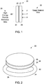
- a target window 20, such as for an isotope production system may be provided that includes a multi-member window structure 22.
- the multi-member window structure 22 is formed from two foil members 24 and 26 to define a dual-foil target window.
- additional members may be provided as desired or needed.
- the relative sizes, thicknesses and materials of the foil members 24 and 26 may be varied as desired or needed and as described in more detail herein.
- the foil members 24 and 26 in various embodiments are separate foils or members aligned in an abutting arrangement as described in more detail herein.
- the foil members 24 and 26 are separately formed or discrete components or elements that are arranged in a stacked arrangement in various embodiments.
- the foil members 24 and 26 may define separate layers wherein one surface (e.g., a planar face) or side 25 of one of the foil members 24 and 26 engages one surface or side 27 of the other one of the foil members 24 and 26 in a stacked or abutting arrangement.
- the foil member 24 is positioned on a high energy particle entrance side 28 of the isotope production system (e.g., high energy particles or other particles enter the target window 20 on this side) and the foil member 26 is positioned on a target material side 30 of the isotope production system, which in various embodiments is a water target.
- a pressure force exists from the target material side 30 to the high energy particle entrance side 28 (illustrated by the P arrows) resulting from the vacuum force on the high energy particle entrance side 28 and the pressure force on the target material side 30.
- the pressure force on the target material side 30 is 5-30 times the force on the high energy particle entrance side 28.
- the high energy particle entrance side 28 may be configured differently in different systems.
- configuration of the high energy particle entrance side 28 may be a vacuum side or a vacuum and helium side, among other configurations.
- the materials forming the foil members 24 and 26 in various embodiments are selected based on desired or needed properties or characteristics.
- the foil member 24 is formed from a material that provides a needed strength to resist high pressure and high temperature conditions, such as an alloy disc formed from a heat treatable cobalt base alloy, such as Havar.
- the foil member 24 has a tensile strength of at least 1000 MPa (mega-Pascals).
- the foil member 26 in some embodiments is formed from a material that has a particular characteristic, such as minimizing the transfer of long-lived radioactive isotopes to the target media or that includes chemically inert materials in contact with a target media, such as a Niobium material.
- one foil member namely the foil member 24 provides strength for the multi-member window structure 22 to resist the vacuum force and the other foil member, namely the foil member 26 reduces the production of long-lived isotopes.
- the foil member 24 is positioned towards or on the high energy particle entrance side 28 and the foil member 26 is positioned towards or on the target material side 30.
- one of the members 24 and 26 or an additional member is formed from aluminum or other heat dissipating or transport material, such as copper.
- the aluminum member (or other dissipation or heat transport member) may be added, which may positioned between the first and second members 24 and 26 in one embodiment, such as between the Havar and Niobium members.
- the foils member may be stacked differently.
- the different members may be arranged or stacked to obtain desired or required overall properties based on the specific properties or characteristics of the members.
- the Havar material provides strength
- the Niobium material provides chemically inert properties
- the optional member formed from aluminum material provides thermal properties, such as heat dissipation.
- a higher strength material is used, which may be Havar, a material having properties similar to Havar or a material having properties different than Havar.
- a higher strength foil member is not provided.
- a Havar foil member is not provided.
- the thickness of the members may be varied, such as based on the energy of the system or other parameters.
- the different foil members are formed or configured based on a particular parameter of interest.
- some properties may include:
- different members may be formed or stacked in different orders to obtain different properties or characteristics.
- the foil members 24 and 26 may be configured having a different shape or size.
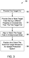
- the foil members 24 and 26 may be foil discs aligned in a stacked arrangement as shown in Figure 2 , which also illustrates an optional member 38, for example, an aluminum member.
- the foil members 24 and 26 are generally aligned in a stacked or sandwiched arrangement and held in place, such as against a frame 32 by the pressure force difference between the high energy particle entrance side 28 and the target material side 30.
- the frame generally includes an opening therethrough 34 that together with the foil members 24 and 26 define the target window 20.
- the higher pressure side foil illustrated as the foil member 26 in Figure 1 is pressed against the lower pressure side foil, illustrated as the foil member 24 in Figure 1 , which is pressed against the frame 32, such as to a support area 36 (e.g., a rim) of the frame 32. Accordingly, the foil member 24 provides a back support structure for the foil member 26.
- the foil members 24 and 26, as well as the member 38 may have different thicknesses.
- the foil member 24 is formed from Havar and has a thickness of about 5-200 micrometers (microns) (e.g., 25-50 microns) and the foil member 26 is formed from Niobium and has a thickness of about 5-200 microns (e.g., 5-20 microns, such as 10 microns).
- the optional member 38 is included, in one embodiment, the member 38 is formed from aluminum and has a thickness of about 50-300 microns.
- the thicknesses may be varied as desired or needed, for example, depending on the energy produced by the system.
- the various foil members range in thickness from about 5 microns to about 300 microns, for example, based on the energy of the system of as otherwise desired or required.
- the foil members may have greater or lesser thicknesses, for example, up to 400 microns or greater.
- the foil members also may have the same or different thicknesses.
- the material compositions of the various members may be varied.
- the foil members 24 and 26 may be formed from a combination of materials, such as a composite material to provide certain properties or characteristics, as well as different alloys.
- the foil members 24 and 26 may be formed from materials having different grain sizes.
- two or more of the members may be formed from the same material or a single member may be formed from different sub-members having the same or different material(s).
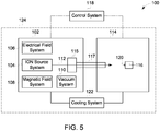
- a method 50 for forming a target window in accordance with various embodiments is shown in Figure 3 .
- the target window may be used, for example, in an isotope production system having a particle accelerator used to produce one or more radioisotopes, for example, 13N-ammonia.
- the method 50 includes providing a first target foil at 52.
- the first target foil provides one or more properties or characteristics, such as a particular tensile strength and melting point.
- a Cobalt based alloy foil, such as Havar may be used.
- the first target member in various embodiments has a tensile strength of at least 1000 MPa and a melting point of at least 1200 degrees Celsius. However, in other embodiments, materials with greater or lesser tensile strength or melting point may be used.
- the method 50 also includes providing one or more target foils at 54. At least one of the additional target foils has a different property or characteristic than the first target foil, such as a different property of interest.
- the second target foil is formed from material that is chemically inert, such as Niobium. Additional target foils also may be provided, such as a foil having thermal dissipation properties, for example, an aluminum foil.
- the thicknesses of the different foils may be determined based on different parameters, such as the energy of the isotope production system or an overall desired property. Additionally, if a member is formed from an alloy or composite, the quantity of different materials also may be varied. In various embodiments, the materials for each of the foils may be determined or selected based on different parameters of interest as described in more detail herein.
- the method 50 further includes aligning or stacking the target foils in a determined order at 56.
- the foils may be stacked to provide individual or overall properties for use in connection with a particular isotope production system.
- the thicknesses of the materials as illustrated by the curves 62 and 64 in graph 60 and the thicknesses of the materials as illustrated by the curves 68 and 70 in graph 66 may affect one or more properties of the foil.
- an overall property as illustrated by the graph 72 may be affected by the thicknesses of the combined materials forming each of the foils as illustrated by the curve 74.
- a determination may be made at to a desired thickness for each of the foils.
- particular properties may be defined.
- at least one unexpected overall property is provided, such as a target window having the tensile strength for use in an isotope production system while providing almost a total reduction of long-lived isotopes in the target material (e.g., water).
- target material e.g., water
- the method 50 then includes positioning or orienting the multi-foil target window in an isotope production system at 58.
- one of the foils may be positioned towards a high energy particle entrance side and the other foil may be positioned toward a target material side.
- FIG. 5 is a block diagram of an isotope production system 100 formed in accordance with various embodiments in which a multi-foil target window may be provided.
- the system 100 includes a cyclotron 102 having several sub-systems including an ion source system 104, an electrical field system 106, a magnetic field system 108, and a vacuum system 110.
- a cyclotron 102 having several sub-systems including an ion source system 104, an electrical field system 106, a magnetic field system 108, and a vacuum system 110.
- the magnetic field system 108 and electrical field system 106 generate respective fields that cooperate with one another in producing a particle beam 112 of the charged particles.
- the system 100 has an extraction system 115 and a target system 114 that includes a target material 116 (e.g., water).
- the target system 114 may be positioned inside, adjacent to or distance from an acceleration chamber of the cyclotron 102.
- the particle beam 112 is directed by the cyclotron 102 through the extraction system 115 along a beam transport path or beam passage 117 and into the target system 114 so that the particle beam 112 is incident upon the target material 116 located at a corresponding target location 120.
- the target material 116 is irradiated with the particle beam 112, radiation from neutrons and gamma rays may be generated, which pass through the target window 20 (shown in Figure 1 ).
- the cyclotron 102 and target system 114 are not separated by a space or gap (e.g., separated by a distance) and/or are not separate parts. Accordingly, in these embodiments, the cyclotron 102 and target system 114 may form a single component or part such that the beam passage 117 between components or parts is not provided.
- the system 100 may have one or more ports, for example, one to ten ports, or more.
- the system 100 includes one or more target locations 120 when one or more target materials 116 are located (one location 120 with one target material 116 is illustrated in Figure 5 ).
- a shifting device or system (not shown) may be used to shift the target locations with respect to the particle beam 112 so that the particle beam 112 is incident upon a different target material 116.
- a vacuum may be maintained during the shifting process as well.
- the cyclotron 102 and the extraction system 115 may not direct the particle beam 112 along only one path, but may direct the particle beam 112 along a unique path for each different target location 120 (if provided).
- the beam passage 117 may be substantially linear from the cyclotron 102 to the target location 120 or, alternatively, the beam passage 117 may curve or turn at one or more points there along.
- magnets positioned alongside the beam passage 117 may be configured to redirect the particle beam 112 along a different path. It should be noted that although the various embodiments may be described in connection with a smaller cyclotron using smaller energies or beam currents, the various embodiments may be implemented in connection with larger cyclotrons having higher energies or beam currents.
- isotope production systems and/or cyclotrons having one or more of the sub-systems are described in U.S. Patent Nos. 6,392,246 ; 6,417,634 ; 6,433,495 ; and 7,122,966 and in U.S. Patent Application Publication No. 2005/0283199 . Additional examples are also provided in U.S. Patent Nos. 5,521,469 ; 6,057,655 ; 7,466,085 ; and 7,476,883 . Furthermore, isotope production systems and/or cyclotrons that may be used with embodiments described herein are also described in co-pending U.S. Patent Application Nos. 12/492,200 ; 12/435,903 ; 12/435,949 ; and 12/435,931 .
- the system 100 is configured to produce radioisotopes (also called radionuclides) that may be used in medical imaging, research, and therapy, but also for other applications that are not medically related, such as scientific research or analysis.
- radioisotopes also called radionuclides
- the radioisotopes may also be called tracers.
- the system 100 may generate protons to make different isotopes.
- the system 100 may also generate protons or deuterons in order to produce, for example, different gases or labeled water.
- various embodiments may be implemented in connection with systems that have particles with any energy level as desired or needed.
- various embodiments may be implemented in systems with any type of high energy particle, such as in connection with systems having accelerators that use very heavy and specific atoms for acceleration.
- the system 100 uses 1 H - technology and brings the charged particles to a low energy (e.g., about 16.5 MeV) with a beam current of approximately 1-200 ⁇ A.
- the negative hydrogen ions are accelerated and guided through the cyclotron 102 and into the extraction system 115.
- the negative hydrogen ions may then hit a stripping foil (not shown in Figure 4 ) of the extraction system 115 thereby removing the pair of electrons and making the particle a positive ion, 1 H + .
- the charged particles may be positive ions, such as 1 H + , 2 H + , and 3 He + .
- the extraction system 115 may include an electrostatic deflector that creates an electric field that guides the particle beam toward the target material 116.
- the various embodiments are not limited to use in lower energy systems, but may be used in higher energy systems, for example, up to 25 MeV and higher energy or beam currents.
- the beam current may be approximately 5 ⁇ A to over approximately 200 ⁇ A.
- the system 100 may include a cooling system 122 that transports a cooling or working fluid to various components of the different systems in order to absorb heat generated by the respective components.
- the system 100 may also include a control system 118 that may be used by a technician to control the operation of the various systems and components.
- the control system 118 may include one or more user-interfaces that are located proximate to or remotely from the cyclotron 102 and the target system 114.
- the system 100 may also include one or more radiation and/or magnetic shields for the cyclotron 102 and the target system 114, as described in more detail below.
- the system 100 may produce the isotopes in predetermined amounts or batches, such as individual doses for use in medical imaging or therapy. Accordingly, isotopes having different levels of activity may be provided. However, the isotopes may be produced in different quantities and in different ways. For example, the various embodiments may provide bulk isotope production, such that are larger amount of the isotope is produced and then specific amounts or individual doses are dispensed.
- the system 100 may be configured to accelerate the charged particles to a predetermined energy level. For example, some embodiments described herein accelerate the charged particles to an energy of approximately 18 MeV or less. In other embodiments, the system 100 accelerates the charged particles to an energy of approximately 16.5 MeV or less. In particular embodiments, the system 100 accelerates the charged particles to an energy of approximately 9.6 MeV or less. In more particular embodiments, the system 100 accelerates the charged particles to an energy of approximately 8 MeV or less. Other embodiments accelerate the charged particles to an energy of approximately 18 MeV or more, for example, 20 MeV or 25 MeV. In still other embodiments, the charged particles may be accelerated to an energy of greater than 25 MeV.
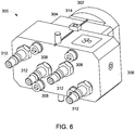
- the target system 114 includes a multi-foil target window within a target body 300 as illustrated in Figures 6 through 9 .
- the target body 300 shown assembled in Figures 6 and 7 (and in exploded view in Figures 8 and 9 ) is formed from several components (illustrated as three components) defining an outer structure of the target body 300.
- the outer structure of the body 300 is formed from a housing portion 302 (e.g., a front housing portion or flange), a housing portion 304 (e.g., cooling housing portion or flange) and housing portion 306 (e.g., a rear housing portion or flange assembly).
- the housing portions 302, 304 and 306 may be, for example, sub-assemblies secured together using any suitable fastener, illustrated as a plurality of screws 308 each having a corresponding washer 310.
- the housing portions 302 and 306 may be end housing portions with the housing portion 304 being an intermediate housing portion.
- the housing portions 302, 304 and 306 form a sealed target body 300 having a plurality of ports 312 on a front surface of the housing portion 306, which in the illustrated embodiment operate as helium and water inlets and outlets that may be connected to helium and water supplies (not shown). Additionally, additional ports or openings 314 may be provided on top and bottom portions of the target body 300. The openings 314 may be provided for receiving fittings or other portions of a port therein.
- a passageway for the charged particle is provided within the target body 300, for example, a path for a proton beam that may enter the target body as illustrated by the arrow P in Figure 8 .
- the charged particles travel through the target body 300 from a tubular opening 319, which acts as a particle path entrance, to a cavity 318 (shown in Figure 8 ) that is a final destination of the changed particles.
- the cavity 318 in various embodiments is water filled, for example, with about 2.5 milliliters (ml) of water, thereby providing a location for irradiated water (H 2 18 O). In another embodiment, about 4 milliliters of H 2 16 O is used.
- the cavity 318 is defined within a body 320 formed, for example, from a Niobium material having a cavity 322 with an opening on one face.
- the body 320 includes the top and bottom openings 314 for receiving therein fittings, for example.
- the cavity 318 in various embodiments, is filled with different liquids or with gas.
- the cavity 318 may be filled with a solid target, wherein the irradiated material is, for example, a solid, plated body of suitable material for the production of certain isotopes.
- the irradiated material is, for example, a solid, plated body of suitable material for the production of certain isotopes.
- a solid target or gas target when using a solid target or gas target, a different structure or design is provided.
- the body 320 is aligned between the housing portion 306 and the housing portion 304 between a sealing ring 326 (e.g., an O-ring) adjacent the housing portion 306 and a multi-foil member 328, such as the target window 20 (shown in Figures 1 and 2 ), for example, a disc having one foil member formed from a heat treatable cobalt based alloy, such as Havar, and another foil member formed from an chemically inert material, such as Niobium, adjacent the housing potion 304.
- the housing portion 306 also includes a cavity 330 shaped and sized to receive therein the sealing ring 326 and a portion of the body 320.
- the housing portion 306 includes a cavity 332 sized and shaped to receive therein a portion of the multi-foil member 328.
- the multi-foil member 328 may include a sealing border 336 (e.g., a Helicoflex border) configured to fit within the cavity 322 of the body 320, and the multi-foil member 328 is also aligned with an opening 338 to a passage through the housing portion 304.
- the foil member 340 may be a disc similar to the multi-foil member 328 or may include only a single foil member in some embodiments.
- the foil member 340 aligns with the opening 338 of the housing portion 304 having an annular rim 342 there around.
- a seal 344, a sealing ring 346 aligned with an opening 348 of the housing portion 302 and a sealing ring 350 fitting onto a rim 352 of the housing portion 302 are provided between the foil member 340 and the housing portion 302.
- more or less foil members or foil members may be provided.
- only the foil member 328 is included and the foil member 340 is not included. Accordingly, different foil arrangements are contemplated by the various embodiments.
- the foil members 328 and 340 are not limited to a disc or circular shape and may be provided in different shapes, configurations and arrangements.
- the one or more the foil members 328 and 340, or additional foil members may be square shaped, rectangular shaped, or oval shaped, among others.
- the foil members 328 and 340 are not limited to being formed from particular materials as described herein.
- a plurality of pins 354 are received within openings 356 in each of the housing portions 302, 304 and 306 to align these component when the target body 300 is assembled. Additionally, a plurality of sealing rings 358 align with openings 360 of the housing portion 304 for receiving therethrough the screws 308 that secure within bores 362 (e.g., threaded bores) of the housing portion 302.
- the foil members 328 and 340 may be heavily activated (e.g., radioactivity induced therein).
- the foil members 328 and 340 which may be, for example, thin (e.g., 5-400 microns) foil alloy discs, isolate the vacuum inside the accelerator, and in particular the accelerator chamber and from the water in the cavity 322.
- the foil members 328 and 340 also allow cooling helium to pass therethrough and/or between the foil members 328 and 340.
- the foil members 328 and 340 have a thickness in various embodiments that allows a proton beam to pass therethrough, which results in the foil members 328 and 340 becoming highly radiated and which remain activated.
- housing portions 302, 304 and 306 may be formed from the same materials, different materials or different quantities or combinations of the same or different materials.
- Embodiments described herein are not intended to be limited to generating radioisotopes for medical uses, but may also generate other isotopes and use other target materials. Also the various embodiments may be implemented in connection with different kinds of cyclotrons having different orientations (e.g., vertically or horizontally oriented), as well as different accelerators, such as linear accelerators or laser induced accelerators instead of spiral accelerators. Furthermore, embodiments described herein include methods of manufacturing the isotope production systems, target systems, and cyclotrons as described above.
Claims (15)
- Fenêtre cible (20) pour un système de production d'isotopes (100), la fenêtre cible (20) comprenant :
une pluralité d'éléments de feuille (24, 26) dans un agencement empilé, les éléments de feuille (24, 26) ayant des faces, la face d'au moins un des éléments de feuille (24) venant en prise avec la face d'au moins un des autres éléments de feuille (26), et au moins deux des éléments de feuille (24, 26) étant formés de matériaux différents. - Fenêtre cible (20) selon la revendication 1, la pluralité d'éléments de feuille (24, 26) comprenant des premier et deuxième éléments de feuille qui sont des éléments formés séparément et alignés dans un agencement en butée.
- Fenêtre cible (20) selon la revendication 1, la pluralité d'éléments de feuille (24, 26) comprenant un premier élément de feuille (24) formé d'un matériau à haute résistance et le deuxième élément de feuille (26) formé d'un matériau chimiquement inerte.
- Fenêtre cible (20) selon la revendication 3, le premier élément de feuille (24) étant un élément de feuille de face d'entrée de particules à haute énergie et le deuxième élément de feuille (26) étant un élément de feuille de face de matériau cible.
- Fenêtre cible (20) selon la revendication 3, le premier élément de feuille (24) étant formé d'un matériau ayant des propriétés similaires au Havar.
- Fenêtre cible (20) selon la revendication 3, comprenant en outre un troisième élément de feuille.
- Fenêtre cible (20) selon la revendication 6, le troisième élément de feuille étant formé d'un matériau thermiquement conducteur.
- Fenêtre cible (20) selon la revendication 1, au moins deux éléments de feuille de la pluralité d'éléments de feuille (24, 26) ayant des propriétés de feuille différentes.
- Fenêtre cible (20) selon la revendication 1, au moins deux des éléments de feuille ayant des propriétés de feuille différentes (24, 26), et la pluralité d'éléments de feuille étant agencés dans l'agencement empilé pour avoir une propriété globale souhaitée différente des propriétés des éléments de feuille.
- Fenêtre cible (20) selon la revendication 1, la pluralité d'éléments de feuille (24, 26) comprenant un premier élément de feuille ayant une résistance à la traction d'au moins 1000 MPa pour une épaisseur allant jusqu'à environ 100 micromètres et un deuxième élément de feuille formé d'un métal chimiquement inerte.
- Système de production d'isotopes (100) comprenant :un accélérateur (102) comprenant une chambre d'accélération ; etun système cible (114) situé à l'intérieur, à proximité ou à une certaine distance de la chambre d'accélération, l'accélérateur étant configuré pour diriger un faisceau de particules de la chambre d'accélération vers le système cible (114), le système cible (114) ayant un corps (320) configuré pour contenir un matériau cible et une fenêtre cible (20) à l'intérieur du corps entre une face d'entrée des particules à haute énergie et une face du matériau cible, la fenêtre cible (20) comprenant une pluralité d'éléments de feuille (24, 26) dans un agencement empilé, les éléments de feuille (24, 26) ayant des faces, les faces de différents éléments de feuille de la pluralité d'éléments de feuille (24, 26) venant en prise les unes avec les autres, au moins deux éléments de feuille de la pluralité d'éléments de feuille (24, 26) ayant des propriétés de matériau différentes.
- Système de production d'isotopes (100) selon la revendication 11, l'un des éléments de feuille (24, 26) étant formé d'un matériau de plus grande résistance et un autre des éléments de feuille étant formé d'un matériau chimiquement inerte.
- Système de production d'isotopes (100) selon la revendication 12, l'élément de feuille (24) formé du matériau de résistance supérieure étant orienté vers la face d'entrée des particules de haute énergie et l'élément de feuille (26) formé du matériau chimiquement inerte étant orienté vers la face du matériau cible.
- Système de production d'isotopes (100) selon la revendication 11, comprenant en outre trois éléments de feuille dont un élément de feuille formé d'un matériau thermiquement conducteur.
- Système de production d'isotopes (100) selon la revendication 11, l'un de la pluralité d'éléments de feuille (24, 26) comprenant un élément de feuille formé de Havar.
Applications Claiming Priority (2)
| Application Number | Priority Date | Filing Date | Title |
|---|---|---|---|
| US13/436,222 US9894746B2 (en) | 2012-03-30 | 2012-03-30 | Target windows for isotope systems |
| PCT/US2013/027709 WO2013172909A1 (fr) | 2012-03-30 | 2013-02-26 | Fenêtres cibles pour des systèmes de production d'isotopes |
Publications (2)
| Publication Number | Publication Date |
|---|---|
| EP2832191A1 EP2832191A1 (fr) | 2015-02-04 |
| EP2832191B1 true EP2832191B1 (fr) | 2020-06-03 |
Family
ID=49170845
Family Applications (1)
| Application Number | Title | Priority Date | Filing Date |
|---|---|---|---|
| EP13762606.5A Active EP2832191B1 (fr) | 2012-03-30 | 2013-02-26 | Fenêtres cibles pour des systèmes de production d'isotopes |
Country Status (6)
| Country | Link |
|---|---|
| US (1) | US9894746B2 (fr) |
| EP (1) | EP2832191B1 (fr) |
| JP (1) | JP6352897B2 (fr) |
| CN (1) | CN104206027B (fr) |
| CA (1) | CA2867804C (fr) |
| WO (1) | WO2013172909A1 (fr) |
Families Citing this family (12)
| Publication number | Priority date | Publication date | Assignee | Title |
|---|---|---|---|---|
| CN104010431B (zh) * | 2014-05-15 | 2016-04-06 | 上海原子科兴药业有限公司 | 一种fdg靶系统 |
| JP2017521645A (ja) * | 2014-05-15 | 2017-08-03 | メイヨ フォンデーシヨン フォー メディカル エジュケーション アンド リサーチ | 放射性金属のサイクロトロン生成用の溶液ターゲット |
| US9961756B2 (en) * | 2014-10-07 | 2018-05-01 | General Electric Company | Isotope production target chamber including a cavity formed from a single sheet of metal foil |
| US9991013B2 (en) * | 2015-06-30 | 2018-06-05 | General Electric Company | Production assemblies and removable target assemblies for isotope production |
| US10340051B2 (en) | 2016-02-16 | 2019-07-02 | General Electric Company | Radioisotope production system and method for controlling the same |
| JP6752590B2 (ja) * | 2016-02-29 | 2020-09-09 | 日本メジフィジックス株式会社 | ターゲット装置および放射性核種製造装置 |
| US10595392B2 (en) * | 2016-06-17 | 2020-03-17 | General Electric Company | Target assembly and isotope production system having a grid section |
| US10354771B2 (en) * | 2016-11-10 | 2019-07-16 | General Electric Company | Isotope production system having a target assembly with a graphene target sheet |
| US20180322972A1 (en) * | 2017-05-04 | 2018-11-08 | General Electric Company | System and method for making a solid target within a production chamber of a target assembly |
| US10109383B1 (en) * | 2017-08-15 | 2018-10-23 | General Electric Company | Target assembly and nuclide production system |
| CA3102292A1 (fr) * | 2018-06-06 | 2019-12-12 | Phoenix Neutron Imaging Llc | Ensembles cibles de faisceau d'ions pour la generation de neutrons |
| US11315700B2 (en) | 2019-05-09 | 2022-04-26 | Strangis Radiopharmacy Consulting and Technology | Method and apparatus for production of radiometals and other radioisotopes using a particle accelerator |
Family Cites Families (28)
| Publication number | Priority date | Publication date | Assignee | Title |
|---|---|---|---|---|
| US4364898A (en) | 1980-10-10 | 1982-12-21 | The United States Of America As Represented By The United States Department Of Energy | Method for the preparation of radon-211 |
| JPS6319836Y2 (fr) | 1981-03-12 | 1988-06-02 | ||
| JPS57151600U (fr) | 1981-03-18 | 1982-09-22 | ||
| JPS58117100U (ja) | 1982-02-03 | 1983-08-10 | 三菱電機株式会社 | ビ−ム取出し窓 |
| BE1005530A4 (fr) | 1991-11-22 | 1993-09-28 | Ion Beam Applic Sa | Cyclotron isochrone |
| BE1009669A3 (fr) | 1995-10-06 | 1997-06-03 | Ion Beam Applic Sa | Methode d'extraction de particules chargees hors d'un cyclotron isochrone et dispositif appliquant cette methode. |
| SE513191C2 (sv) | 1998-09-29 | 2000-07-24 | Gems Pet Systems Ab | Snabbkoppling |
| SE513193C2 (sv) | 1998-09-29 | 2000-07-24 | Gems Pet Systems Ab | Integralt strålningsskydd |
| SE513192C2 (sv) | 1998-09-29 | 2000-07-24 | Gems Pet Systems Ab | Förfarande och system för HF-styrning |
| EP1412951A2 (fr) | 2001-06-13 | 2004-04-28 | The Uni. Of Alberta, the Uni. of British Columbia, Carleton Uni., Simon Fraser Uni., the Uni. of Victoria, d.b.a. TRIUMF | Appareil et procede de generation de ?18 f-fluorure au moyen de faisceaux ioniques |
| DE60323832D1 (de) | 2002-05-21 | 2008-11-13 | Univ Duke | Batch-target und verfahren zur erzeugung eines radionuklids |
| EP1569243A1 (fr) | 2004-02-20 | 2005-08-31 | Ion Beam Applications S.A. | Dispositif de cible pour la production d'un radioisotope |
| WO2005122654A1 (fr) | 2004-06-08 | 2005-12-22 | Truimf, Operating As A Joint Venture By The Governors Of The University Of Alberta, The University Of British Columbia, Carleton | Procede de formation de cibles ceramiques composites |
| US7786442B2 (en) | 2004-06-18 | 2010-08-31 | General Electric Company | Method and apparatus for ion source positioning and adjustment |
| US20060062342A1 (en) * | 2004-09-17 | 2006-03-23 | Cyclotron Partners, L.P. | Method and apparatus for the production of radioisotopes |
| US7122966B2 (en) | 2004-12-16 | 2006-10-17 | General Electric Company | Ion source apparatus and method |
| WO2007016783A1 (fr) | 2005-08-05 | 2007-02-15 | Triumf, Operating As A Joint Venture By The Governors Of The University Of Alberta, The University Of British Columbia, Carleton | Procede d'etalonnage d'energie de faisceau de particules |
| JP4099187B2 (ja) | 2005-09-30 | 2008-06-11 | 株式会社日立製作所 | 放射性同位元素製造装置、及びターゲットのリサイクル方法 |
| US7476883B2 (en) | 2006-05-26 | 2009-01-13 | Advanced Biomarker Technologies, Llc | Biomarker generator system |
| US7466085B2 (en) | 2007-04-17 | 2008-12-16 | Advanced Biomarker Technologies, Llc | Cyclotron having permanent magnets |
| EP2171724A1 (fr) * | 2007-06-22 | 2010-04-07 | Advanced Applied Physics Solutions, Inc. | Système de cible modulaire à pression plus élevée pour la production de radioisotopes |
| US20090052628A1 (en) * | 2007-08-24 | 2009-02-26 | Governors Of The Universty Of Alberta | Target foil for use in the production of [18f] using a particle accelerator |
| EP2146555A1 (fr) | 2008-07-18 | 2010-01-20 | Ion Beam Applications S.A. | Appareil cible pour la production de radio-isotopes |
| US8153997B2 (en) | 2009-05-05 | 2012-04-10 | General Electric Company | Isotope production system and cyclotron |
| US8106570B2 (en) | 2009-05-05 | 2012-01-31 | General Electric Company | Isotope production system and cyclotron having reduced magnetic stray fields |
| US8106370B2 (en) | 2009-05-05 | 2012-01-31 | General Electric Company | Isotope production system and cyclotron having a magnet yoke with a pump acceptance cavity |
| US8374306B2 (en) | 2009-06-26 | 2013-02-12 | General Electric Company | Isotope production system with separated shielding |
| US9693443B2 (en) * | 2010-04-19 | 2017-06-27 | General Electric Company | Self-shielding target for isotope production systems |
-
2012
- 2012-03-30 US US13/436,222 patent/US9894746B2/en active Active
-
2013
- 2013-02-26 CA CA2867804A patent/CA2867804C/fr active Active
- 2013-02-26 CN CN201380018275.1A patent/CN104206027B/zh active Active
- 2013-02-26 EP EP13762606.5A patent/EP2832191B1/fr active Active
- 2013-02-26 WO PCT/US2013/027709 patent/WO2013172909A1/fr active Application Filing
- 2013-02-26 JP JP2015503213A patent/JP6352897B2/ja active Active
Non-Patent Citations (1)
| Title |
|---|
| None * |
Also Published As
| Publication number | Publication date |
|---|---|
| CN104206027B (zh) | 2020-04-21 |
| US20130259180A1 (en) | 2013-10-03 |
| JP6352897B2 (ja) | 2018-07-04 |
| CN104206027A (zh) | 2014-12-10 |
| CA2867804C (fr) | 2020-06-16 |
| JP2015512517A (ja) | 2015-04-27 |
| EP2832191A1 (fr) | 2015-02-04 |
| CA2867804A1 (fr) | 2013-11-21 |
| WO2013172909A1 (fr) | 2013-11-21 |
| US9894746B2 (en) | 2018-02-13 |
Similar Documents
| Publication | Publication Date | Title |
|---|---|---|
| EP2832191B1 (fr) | Fenêtres cibles pour des systèmes de production d'isotopes | |
| EP2561727B1 (fr) | Cible à auto-blindage pour systèmes de production d'isotopes | |
| EP3473063B1 (fr) | Ensemble cible et système de production d'isotope comportant une section grille | |
| RU2769259C2 (ru) | Сборка мишени и система производства нуклидов | |
| US20160141062A1 (en) | Target body for an isotope production system and method of using the same | |
| US9196388B2 (en) | System and method for generating molybdenum-99 and metastable technetium-99, and other isotopes | |
| US9894747B2 (en) | Radio-frequency electrode and cyclotron configured to reduce radiation exposure | |
| US10354771B2 (en) | Isotope production system having a target assembly with a graphene target sheet |
Legal Events
| Date | Code | Title | Description |
|---|---|---|---|
| PUAI | Public reference made under article 153(3) epc to a published international application that has entered the european phase |
Free format text: ORIGINAL CODE: 0009012 |
|
| 17P | Request for examination filed |
Effective date: 20141030 |
|
| AK | Designated contracting states |
Kind code of ref document: A1 Designated state(s): AL AT BE BG CH CY CZ DE DK EE ES FI FR GB GR HR HU IE IS IT LI LT LU LV MC MK MT NL NO PL PT RO RS SE SI SK SM TR |
|
| AX | Request for extension of the european patent |
Extension state: BA ME |
|
| DAX | Request for extension of the european patent (deleted) | ||
| GRAP | Despatch of communication of intention to grant a patent |
Free format text: ORIGINAL CODE: EPIDOSNIGR1 |
|
| STAA | Information on the status of an ep patent application or granted ep patent |
Free format text: STATUS: GRANT OF PATENT IS INTENDED |
|
| INTG | Intention to grant announced |
Effective date: 20190904 |
|
| GRAJ | Information related to disapproval of communication of intention to grant by the applicant or resumption of examination proceedings by the epo deleted |
Free format text: ORIGINAL CODE: EPIDOSDIGR1 |
|
| STAA | Information on the status of an ep patent application or granted ep patent |
Free format text: STATUS: REQUEST FOR EXAMINATION WAS MADE |
|
| INTC | Intention to grant announced (deleted) | ||
| GRAP | Despatch of communication of intention to grant a patent |
Free format text: ORIGINAL CODE: EPIDOSNIGR1 |
|
| STAA | Information on the status of an ep patent application or granted ep patent |
Free format text: STATUS: GRANT OF PATENT IS INTENDED |
|
| INTG | Intention to grant announced |
Effective date: 20200128 |
|
| GRAS | Grant fee paid |
Free format text: ORIGINAL CODE: EPIDOSNIGR3 |
|
| GRAA | (expected) grant |
Free format text: ORIGINAL CODE: 0009210 |
|
| STAA | Information on the status of an ep patent application or granted ep patent |
Free format text: STATUS: THE PATENT HAS BEEN GRANTED |
|
| AK | Designated contracting states |
Kind code of ref document: B1 Designated state(s): AL AT BE BG CH CY CZ DE DK EE ES FI FR GB GR HR HU IE IS IT LI LT LU LV MC MK MT NL NO PL PT RO RS SE SI SK SM TR |
|
| REG | Reference to a national code |
Ref country code: GB Ref legal event code: FG4D |
|
| REG | Reference to a national code |
Ref country code: AT Ref legal event code: REF Ref document number: 1278470 Country of ref document: AT Kind code of ref document: T Effective date: 20200615 Ref country code: CH Ref legal event code: EP |
|
| REG | Reference to a national code |
Ref country code: DE Ref legal event code: R096 Ref document number: 602013069623 Country of ref document: DE |
|
| REG | Reference to a national code |
Ref country code: LT Ref legal event code: MG4D |
|
| PG25 | Lapsed in a contracting state [announced via postgrant information from national office to epo] |
Ref country code: GR Free format text: LAPSE BECAUSE OF FAILURE TO SUBMIT A TRANSLATION OF THE DESCRIPTION OR TO PAY THE FEE WITHIN THE PRESCRIBED TIME-LIMIT Effective date: 20200904 Ref country code: NO Free format text: LAPSE BECAUSE OF FAILURE TO SUBMIT A TRANSLATION OF THE DESCRIPTION OR TO PAY THE FEE WITHIN THE PRESCRIBED TIME-LIMIT Effective date: 20200903 Ref country code: FI Free format text: LAPSE BECAUSE OF FAILURE TO SUBMIT A TRANSLATION OF THE DESCRIPTION OR TO PAY THE FEE WITHIN THE PRESCRIBED TIME-LIMIT Effective date: 20200603 Ref country code: LT Free format text: LAPSE BECAUSE OF FAILURE TO SUBMIT A TRANSLATION OF THE DESCRIPTION OR TO PAY THE FEE WITHIN THE PRESCRIBED TIME-LIMIT Effective date: 20200603 Ref country code: SE Free format text: LAPSE BECAUSE OF FAILURE TO SUBMIT A TRANSLATION OF THE DESCRIPTION OR TO PAY THE FEE WITHIN THE PRESCRIBED TIME-LIMIT Effective date: 20200603 |
|
| REG | Reference to a national code |
Ref country code: NL Ref legal event code: MP Effective date: 20200603 |
|
| PG25 | Lapsed in a contracting state [announced via postgrant information from national office to epo] |
Ref country code: HR Free format text: LAPSE BECAUSE OF FAILURE TO SUBMIT A TRANSLATION OF THE DESCRIPTION OR TO PAY THE FEE WITHIN THE PRESCRIBED TIME-LIMIT Effective date: 20200603 Ref country code: BG Free format text: LAPSE BECAUSE OF FAILURE TO SUBMIT A TRANSLATION OF THE DESCRIPTION OR TO PAY THE FEE WITHIN THE PRESCRIBED TIME-LIMIT Effective date: 20200903 Ref country code: RS Free format text: LAPSE BECAUSE OF FAILURE TO SUBMIT A TRANSLATION OF THE DESCRIPTION OR TO PAY THE FEE WITHIN THE PRESCRIBED TIME-LIMIT Effective date: 20200603 Ref country code: LV Free format text: LAPSE BECAUSE OF FAILURE TO SUBMIT A TRANSLATION OF THE DESCRIPTION OR TO PAY THE FEE WITHIN THE PRESCRIBED TIME-LIMIT Effective date: 20200603 |
|
| REG | Reference to a national code |
Ref country code: AT Ref legal event code: MK05 Ref document number: 1278470 Country of ref document: AT Kind code of ref document: T Effective date: 20200603 |
|
| PG25 | Lapsed in a contracting state [announced via postgrant information from national office to epo] |
Ref country code: AL Free format text: LAPSE BECAUSE OF FAILURE TO SUBMIT A TRANSLATION OF THE DESCRIPTION OR TO PAY THE FEE WITHIN THE PRESCRIBED TIME-LIMIT Effective date: 20200603 Ref country code: NL Free format text: LAPSE BECAUSE OF FAILURE TO SUBMIT A TRANSLATION OF THE DESCRIPTION OR TO PAY THE FEE WITHIN THE PRESCRIBED TIME-LIMIT Effective date: 20200603 |
|
| PG25 | Lapsed in a contracting state [announced via postgrant information from national office to epo] |
Ref country code: ES Free format text: LAPSE BECAUSE OF FAILURE TO SUBMIT A TRANSLATION OF THE DESCRIPTION OR TO PAY THE FEE WITHIN THE PRESCRIBED TIME-LIMIT Effective date: 20200603 Ref country code: AT Free format text: LAPSE BECAUSE OF FAILURE TO SUBMIT A TRANSLATION OF THE DESCRIPTION OR TO PAY THE FEE WITHIN THE PRESCRIBED TIME-LIMIT Effective date: 20200603 Ref country code: EE Free format text: LAPSE BECAUSE OF FAILURE TO SUBMIT A TRANSLATION OF THE DESCRIPTION OR TO PAY THE FEE WITHIN THE PRESCRIBED TIME-LIMIT Effective date: 20200603 Ref country code: SM Free format text: LAPSE BECAUSE OF FAILURE TO SUBMIT A TRANSLATION OF THE DESCRIPTION OR TO PAY THE FEE WITHIN THE PRESCRIBED TIME-LIMIT Effective date: 20200603 Ref country code: IT Free format text: LAPSE BECAUSE OF FAILURE TO SUBMIT A TRANSLATION OF THE DESCRIPTION OR TO PAY THE FEE WITHIN THE PRESCRIBED TIME-LIMIT Effective date: 20200603 Ref country code: RO Free format text: LAPSE BECAUSE OF FAILURE TO SUBMIT A TRANSLATION OF THE DESCRIPTION OR TO PAY THE FEE WITHIN THE PRESCRIBED TIME-LIMIT Effective date: 20200603 Ref country code: CZ Free format text: LAPSE BECAUSE OF FAILURE TO SUBMIT A TRANSLATION OF THE DESCRIPTION OR TO PAY THE FEE WITHIN THE PRESCRIBED TIME-LIMIT Effective date: 20200603 Ref country code: PT Free format text: LAPSE BECAUSE OF FAILURE TO SUBMIT A TRANSLATION OF THE DESCRIPTION OR TO PAY THE FEE WITHIN THE PRESCRIBED TIME-LIMIT Effective date: 20201006 |
|
| PG25 | Lapsed in a contracting state [announced via postgrant information from national office to epo] |
Ref country code: IS Free format text: LAPSE BECAUSE OF FAILURE TO SUBMIT A TRANSLATION OF THE DESCRIPTION OR TO PAY THE FEE WITHIN THE PRESCRIBED TIME-LIMIT Effective date: 20201003 Ref country code: PL Free format text: LAPSE BECAUSE OF FAILURE TO SUBMIT A TRANSLATION OF THE DESCRIPTION OR TO PAY THE FEE WITHIN THE PRESCRIBED TIME-LIMIT Effective date: 20200603 Ref country code: SK Free format text: LAPSE BECAUSE OF FAILURE TO SUBMIT A TRANSLATION OF THE DESCRIPTION OR TO PAY THE FEE WITHIN THE PRESCRIBED TIME-LIMIT Effective date: 20200603 |
|
| REG | Reference to a national code |
Ref country code: DE Ref legal event code: R097 Ref document number: 602013069623 Country of ref document: DE |
|
| PLBE | No opposition filed within time limit |
Free format text: ORIGINAL CODE: 0009261 |
|
| STAA | Information on the status of an ep patent application or granted ep patent |
Free format text: STATUS: NO OPPOSITION FILED WITHIN TIME LIMIT |
|
| PG25 | Lapsed in a contracting state [announced via postgrant information from national office to epo] |
Ref country code: DK Free format text: LAPSE BECAUSE OF FAILURE TO SUBMIT A TRANSLATION OF THE DESCRIPTION OR TO PAY THE FEE WITHIN THE PRESCRIBED TIME-LIMIT Effective date: 20200603 |
|
| 26N | No opposition filed |
Effective date: 20210304 |
|
| PG25 | Lapsed in a contracting state [announced via postgrant information from national office to epo] |
Ref country code: SI Free format text: LAPSE BECAUSE OF FAILURE TO SUBMIT A TRANSLATION OF THE DESCRIPTION OR TO PAY THE FEE WITHIN THE PRESCRIBED TIME-LIMIT Effective date: 20200603 |
|
| REG | Reference to a national code |
Ref country code: DE Ref legal event code: R119 Ref document number: 602013069623 Country of ref document: DE |
|
| PG25 | Lapsed in a contracting state [announced via postgrant information from national office to epo] |
Ref country code: MC Free format text: LAPSE BECAUSE OF FAILURE TO SUBMIT A TRANSLATION OF THE DESCRIPTION OR TO PAY THE FEE WITHIN THE PRESCRIBED TIME-LIMIT Effective date: 20200603 |
|
| GBPC | Gb: european patent ceased through non-payment of renewal fee |
Effective date: 20210226 |
|
| PG25 | Lapsed in a contracting state [announced via postgrant information from national office to epo] |
Ref country code: CH Free format text: LAPSE BECAUSE OF NON-PAYMENT OF DUE FEES Effective date: 20210228 Ref country code: LI Free format text: LAPSE BECAUSE OF NON-PAYMENT OF DUE FEES Effective date: 20210228 Ref country code: LU Free format text: LAPSE BECAUSE OF NON-PAYMENT OF DUE FEES Effective date: 20210226 |
|
| PG25 | Lapsed in a contracting state [announced via postgrant information from national office to epo] |
Ref country code: IE Free format text: LAPSE BECAUSE OF NON-PAYMENT OF DUE FEES Effective date: 20210226 Ref country code: GB Free format text: LAPSE BECAUSE OF NON-PAYMENT OF DUE FEES Effective date: 20210226 Ref country code: FR Free format text: LAPSE BECAUSE OF NON-PAYMENT OF DUE FEES Effective date: 20210228 Ref country code: DE Free format text: LAPSE BECAUSE OF NON-PAYMENT OF DUE FEES Effective date: 20210901 |
|
| PG25 | Lapsed in a contracting state [announced via postgrant information from national office to epo] |
Ref country code: HU Free format text: LAPSE BECAUSE OF FAILURE TO SUBMIT A TRANSLATION OF THE DESCRIPTION OR TO PAY THE FEE WITHIN THE PRESCRIBED TIME-LIMIT; INVALID AB INITIO Effective date: 20130226 |
|
| PGFP | Annual fee paid to national office [announced via postgrant information from national office to epo] |
Ref country code: BE Payment date: 20230119 Year of fee payment: 11 |
|
| PG25 | Lapsed in a contracting state [announced via postgrant information from national office to epo] |
Ref country code: CY Free format text: LAPSE BECAUSE OF FAILURE TO SUBMIT A TRANSLATION OF THE DESCRIPTION OR TO PAY THE FEE WITHIN THE PRESCRIBED TIME-LIMIT Effective date: 20200603 |
|
| P01 | Opt-out of the competence of the unified patent court (upc) registered |
Effective date: 20230528 |
|
| PG25 | Lapsed in a contracting state [announced via postgrant information from national office to epo] |
Ref country code: MK Free format text: LAPSE BECAUSE OF FAILURE TO SUBMIT A TRANSLATION OF THE DESCRIPTION OR TO PAY THE FEE WITHIN THE PRESCRIBED TIME-LIMIT Effective date: 20200603 |