EP2831856B1 - Système et procédé permettant de détecter la présence d'un objet - Google Patents
Système et procédé permettant de détecter la présence d'un objet Download PDFInfo
- Publication number
- EP2831856B1 EP2831856B1 EP13716107.1A EP13716107A EP2831856B1 EP 2831856 B1 EP2831856 B1 EP 2831856B1 EP 13716107 A EP13716107 A EP 13716107A EP 2831856 B1 EP2831856 B1 EP 2831856B1
- Authority
- EP
- European Patent Office
- Prior art keywords
- signals
- rfid reader
- rfid
- tag
- mixing element
- Prior art date
- Legal status (The legal status is an assumption and is not a legal conclusion. Google has not performed a legal analysis and makes no representation as to the accuracy of the status listed.)
- Active
Links
- 238000000034 method Methods 0.000 title claims description 18
- 230000004044 response Effects 0.000 claims description 81
- 238000001514 detection method Methods 0.000 claims description 39
- 238000004806 packaging method and process Methods 0.000 claims description 4
- 238000012544 monitoring process Methods 0.000 description 5
- 239000002184 metal Substances 0.000 description 4
- 230000008569 process Effects 0.000 description 4
- 238000012545 processing Methods 0.000 description 4
- 230000005684 electric field Effects 0.000 description 3
- 239000003990 capacitor Substances 0.000 description 2
- 230000008859 change Effects 0.000 description 2
- 238000004891 communication Methods 0.000 description 2
- 238000010586 diagram Methods 0.000 description 2
- 239000000463 material Substances 0.000 description 2
- 238000012986 modification Methods 0.000 description 2
- 230000004048 modification Effects 0.000 description 2
- 239000000758 substrate Substances 0.000 description 2
- 230000001960 triggered effect Effects 0.000 description 2
- 239000000853 adhesive Substances 0.000 description 1
- 230000001070 adhesive effect Effects 0.000 description 1
- 239000012790 adhesive layer Substances 0.000 description 1
- 230000005540 biological transmission Effects 0.000 description 1
- 230000005672 electromagnetic field Effects 0.000 description 1
- 230000006870 function Effects 0.000 description 1
- 230000003993 interaction Effects 0.000 description 1
- 238000004519 manufacturing process Methods 0.000 description 1
- 239000003550 marker Substances 0.000 description 1
- 230000011664 signaling Effects 0.000 description 1
- 238000012546 transfer Methods 0.000 description 1
Images


Classifications
-
- G—PHYSICS
- G08—SIGNALLING
- G08B—SIGNALLING OR CALLING SYSTEMS; ORDER TELEGRAPHS; ALARM SYSTEMS
- G08B13/00—Burglar, theft or intruder alarms
- G08B13/22—Electrical actuation
- G08B13/24—Electrical actuation by interference with electromagnetic field distribution
- G08B13/2402—Electronic Article Surveillance [EAS], i.e. systems using tags for detecting removal of a tagged item from a secure area, e.g. tags for detecting shoplifting
- G08B13/2465—Aspects related to the EAS system, e.g. system components other than tags
- G08B13/2482—EAS methods, e.g. description of flow chart of the detection procedure
-
- G—PHYSICS
- G08—SIGNALLING
- G08B—SIGNALLING OR CALLING SYSTEMS; ORDER TELEGRAPHS; ALARM SYSTEMS
- G08B13/00—Burglar, theft or intruder alarms
- G08B13/22—Electrical actuation
- G08B13/24—Electrical actuation by interference with electromagnetic field distribution
- G08B13/2402—Electronic Article Surveillance [EAS], i.e. systems using tags for detecting removal of a tagged item from a secure area, e.g. tags for detecting shoplifting
- G08B13/2405—Electronic Article Surveillance [EAS], i.e. systems using tags for detecting removal of a tagged item from a secure area, e.g. tags for detecting shoplifting characterised by the tag technology used
- G08B13/2414—Electronic Article Surveillance [EAS], i.e. systems using tags for detecting removal of a tagged item from a secure area, e.g. tags for detecting shoplifting characterised by the tag technology used using inductive tags
- G08B13/2417—Electronic Article Surveillance [EAS], i.e. systems using tags for detecting removal of a tagged item from a secure area, e.g. tags for detecting shoplifting characterised by the tag technology used using inductive tags having a radio frequency identification chip
-
- G—PHYSICS
- G08—SIGNALLING
- G08B—SIGNALLING OR CALLING SYSTEMS; ORDER TELEGRAPHS; ALARM SYSTEMS
- G08B13/00—Burglar, theft or intruder alarms
- G08B13/22—Electrical actuation
- G08B13/24—Electrical actuation by interference with electromagnetic field distribution
- G08B13/2402—Electronic Article Surveillance [EAS], i.e. systems using tags for detecting removal of a tagged item from a secure area, e.g. tags for detecting shoplifting
- G08B13/2428—Tag details
- G08B13/2448—Tag with at least dual detection means, e.g. combined inductive and ferromagnetic tags, dual frequencies within a single technology, tampering detection or signalling means on the tag
Definitions
- Embodiments of the present disclosure generally relate to a system and method of detecting the presence of an object, such as merchandise within a retail establishment.
- Embodiments of the present disclosure relate to systems and methods of theft detection and deterrence, for example.
- RFID radio-frequency identification
- RFID systems may be used to track products for purposes of inventory, logistics, and the like.
- An RFID system is typically a wireless, non-contact system that uses radio-frequency (RF) electromagnetic fields to transfer data from a tag or label attached to an object in order to identify and track the object.
- RF radio-frequency
- an RFID tag which may be embedded within an object, does not need to be within an area of sight of an RFID reader.
- RFID tags may be secured to articles of clothing, for example.
- an RFID system typically includes tags or labels attached to the objects that are to be tracked and identified.
- Two-way radio transmitter-receivers such as interrogators or readers, send signals to the tag and read the response from the tag.
- the readers typically transmit observations regarding the tag or label to a computer system running RFID software, for example.
- the RFID tag includes a small RF transmitter and receiver.
- An RFID reader transmits an encoded radio signal to interrogate the tag.
- the tag receives the message and responds with identification information.
- the identification information may be a unique tag serial number, or product-related information such as a stock number, lot or batch number, production date, or other specific information.
- RFID tags may be either passive, active, or battery assisted passive.
- An active RFID tag typically includes an on-board battery that periodically transmits an ID signal.
- a battery assisted passive (BAP) typically includes a small battery that is activated when in the presence of an RFID reader.
- BAP battery assisted passive
- a passive RFID tag typically does not include a battery. Instead, the tag uses RF energy transmitted by the reader as its energy source.
- RFID tags have individual serial numbers, the RFID system is able to discriminate among several tags that are within the range of the RFID reader.
- RFID tags may include an integrated circuit for storing and processing information, modulating and demodulating a radio-frequency (RF) signal, collecting direct current power from the incident reader signal, and other specialized functions, and an antenna for receiving and transmitting the signal.
- RF radio-frequency
- EAS Electronic article surveillance
- a system transmitter and a system receiver are used to establish a surveillance zone, which must be traversed by any article being removed from the controlled area.
- An EAS tag is affixed to each article and includes a marker or sensor adapted to interact with a signal that is transmitted by the system transmitter into the surveillance zone. The interaction causes a further signal to be established in the surveillance zone, which is received by the system receiver. Accordingly, upon movement of a tagged article through the surveillance zone, a signal is received by the system receiver, identifying the unauthorized presence of the tagged article in the zone.
- an EAS tag typically provides a disturbance or response to an electric or magnetic field.
- a business that wishes to track inventory and provide theft detection and deterrence employs separate and distinct systems for each.
- the business may include an RFID system for inventory and logistics, and an EAS system for theft detection and deterrence.
- an RFID system for inventory and logistics may include an RFID system for inventory and logistics, and an EAS system for theft detection and deterrence.
- EAS system for theft detection and deterrence.
- employing two separate and distinct systems increases costs.
- RFID and EAS tags have been combined into a common enclosure.
- the RFID and EAS tags operate separately and distinetly from one another, and typically require separate and distinct RFID and EAS detection systems, respectively, to detect their presence.
- typical EAS systems are incompatible with radio frequency ranges that are used with high and ultra-high frequency RFID systems.
- US 2006/273902 A1 discloses a system for detecting the presence of an object, the system comprising: a radio frequency identification, RFID, reader configured to transmit a plurality of interrogation signals; a transmitter that is configured to transmit a plurality of standard signals; and a mixing element secured to the object to be detected that is configured to generate a mixed signal when in the presence of the plurality of interrogation signals and the standard signals, wherein the RFID reader outputs an event or alert signal upon receipt of the mixed signal.
- a radio frequency identification, RFID, reader configured to transmit a plurality of interrogation signals
- a transmitter that is configured to transmit a plurality of standard signals
- a mixing element secured to the object to be detected that is configured to generate a mixed signal when in the presence of the plurality of interrogation signals and the standard signals, wherein the RFID reader outputs an event or alert signal upon receipt of the mixed signal.
- the invention provides a system for detecting the presence of an object.
- the system includes a radio frequency identification (RFID) reader configured to transmit a plurality of interrogation signals, a response controller, such as an electric field (“E-field”) RFID response controller, that is configured to receive the plurality of interrogation signals and respond by transmitting a plurality of standard response signals, and a mixing element secured to the object to be detected that is configured to generate a mixed signal when in the presence of the plurality of interrogation signals and the standard response signals.
- the RFID reader outputs an alert or event signal upon receipt of the mixed signal, and report an event that triggered the alert through a communication channel.
- the plurality of standard response signals may be modulated.
- the plurality of standard response signals may be transmitted at a low frequency, such as between 100-250 kHz, and the plurality of interrogation signals may be transmitted at an ultra-high frequency, such as between 100-1000 MHz.
- the mixed signal may be a mix of the plurality of standard response signals and the plurality of interrogation signals.
- the system may also include at least one detection member configured to generate one or both of an electric or magnetic field.
- the detection members may include metal plates and/or loop antennas configured to generate an electric and/or magnetic field.
- the detection members(s) may be operatively connected to the response controller.
- the system may also include a tag.
- the mixing element may be encased within the tag.
- the tag may also include an RFID tag or element.
- the mixing element may be part of a label on a product or product packaging.
- the mixing element may be part of an electronic article surveillance (EAS) microwave tag.
- EAS electronic article surveillance
- the RFID reader and the response controller may be contained within a common housing.
- the invention provides also a method of detecting the presence of an object.
- the method includes using an RFID reader to transmit a plurality of interrogation signals, receiving the plurality of interrogation signals at a response controller, using the response controller to transmit a plurality of standard response signals upon reception of the plurality of interrogation signals, disregarding the standard response signals, generating a mixed signal when a mixing element secured to the object to be detected is in the presence of the plurality of interrogation signals and the plurality of standard response signals, and outputting an alert signal through the RFID reader upon receipt of the mixed signal.
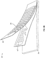
- FIG. 1 illustrates an isometric view of a front entrance 10 of an establishment 12, according to an embodiment of the present disclosure.
- the establishment 12 may be a retail store, for example.
- the front entrance 10 includes one or more doors 14 that permit individuals to enter and exit the establishment.
- opposed detection members 16, such as posts, panels, or the like, are positioned proximate the doors 14.
- the opposed detection members 16 may be a doorway or threshold through which an individual may pass.
- the detection members 16 may include metal plates configured to generate an electric field therebetween.
- the detection members 16 may include wire coils configured to generate a magnetic field.
- the detection members 16 may include an RFID reader and a response controller, such as an E-field RFID response controller, as described below.
- FIG. 2a illustrates a simplified view of a tag 18, according to an embodiment of the present disclosure.
- the tag 18 is configured to be attached to an article for sale, such as an article of clothing, and may be an EAS microwave tag, label, or the like.
- the tag 18 may include an inlay 19 that contains or otherwise supports an internal antenna 20 connected to a mixing element 22.
- the element 22 may be a non-linear element, such as a diode or variable capacitor that changes characteristics based on an applied voltage.
- the mixing element 22 may generate a separate and distinct signal based on the signaling of the response controller.
- the tag 18 may also include an RFID tag inlay, which may be detected by an RFID reader.
- the inlay 19 having the mixing element 22 and the antenna 20 may be integrally secured to an article for sale, and/or assembled in a paper or plastic label.
- the inlay 19 may be secured to a box, packaging, or the like that contains a product for sale.
- FIG. 2b illustrates an inlay 19' formed with a label 23, according to an embodiment of the present disclosure.
- the inlay 19' may include a mixing element and antenna, as described above.
- the inlay 19' is supported on a substrate 24, such as through an adhesive liner.
- the inlay 19' may be overlaid with a bar code strip 26, which may include an adhesive layer 28 on a lower surface. As such, the inlay 19' may be compressively and adhesively sandwiched between the bar code strip 26 and the substrate 24.
- FIG 3 illustrates a block diagram of an object detection system 30, according to an embodiment of the present disclosure.
- the system 30 may include an RFID reader 32 and a signal or field generator 34, which may be, for example, an E-field RFID response controller.
- the RFID reader 32 and the signal or field generator 34 may be the opposed detection members 16 (shown in Figure 1 ), for example.
- the RFID reader 32 may include a transmitter 35 and a receiver 36.
- the transmitter 35 is configured to transmit ultra-high frequency querying signals over a first band or channel.
- the transmitter 35 may transmit querying signals at a frequency of 915 MHz, for example.
- the receiver 36 is configured to receive signals transmitted from RFID tags, for example, and from a mixing element, which may be an EAS tag, such as the mixing element 22 (shown in Figure 2a ).
- the transmitter 35 and the receiver 36 are operatively connected to a processing unit 38 (such as a microprocessor, microcontroller, integrated circuit, and/or the like), which may include a memory, or may be operatively connected to separate and distinct memory.
- the RFID reader 32 may be housed within, or server as, one of the detection members 16.
- the RFID reader 32 may be at various other locations within the establishment 12.
- the RFID reader 32 may be secured to a ceiling of the establishment 12 over the detection members 16.
- the response controller 34 includes a receiving antenna 40 and a transmitting antenna 42, both of which are operatively connected to a processing unit 44.
- the receiving and transmitting antennas 40 and 42 may be integrated into a single structure.
- the processing unit 44 may include, or be separately connected to, a memory.
- the response controller 34 may be housed within, or serve as, one of the detection members 16.
- the response controller 34 may be at various other locations within the establishment 12. For example, the response controller 34 may be secured to a ceiling of the establishment 12 over the detection members 16. Additionally, the response controller 34 and the RFID reader 30 may be secured within a common housing,
- the response controller 34 In operation, the response controller 34 generates a low frequency signal over a second band or channel that differs from the first band or channel.
- the low frequency signal may generate one or both of an electric or magnetic field between the detection members 16.
- the response controller 34 may be directly wired to metal plates within the detection members 16 to produce an electric field.
- the response controller 34 may be directly wired to wire coils that are configured to generate a magnetic field.
- the response controller 34 may produce an electric and/or magnetic field in the metal plates or coils through transmission of a modulated, low frequency standard response signal 52 transmitted through the antenna 42.
- the response controller 34 may modulate the generated low frequency standard signal between on and off states.
- the RFID reader 30 transmits interrogation signals 50 that are received by the receiving antenna 40 of the response controller 34.
- the response controller 34 transmits the modulated low frequency standard response signals 52 back to the RFID reader 30.
- the response controller 34 modulates a low-frequency signal that selectively activates and deactivates the electric or magnetic field between the detection members 16.
- the RFID reader 32 receives a series of signals from the transmitter 42 of the response controller 34.
- the response controller 34 acts as an RFID tag simulator in that the RFID reader 32 receives a series of signals that are akin to data signals transmitted from an RFID tag.
- the response controller 34 may modulate the low frequency standard signals 52 so that they are received by the RFID reader 32 similar to an RFID response signal from an RFID tag, such as an RN16 (random number with 16 bits) signal.
- the response controller 34 in response to the interrogation signals 50 transmitted from the RFID reader 32, transmits the low frequency standard response signals 52 at a particular frequency to the RFID reader 32.
- the response signals 52 are at a frequency, however, that the RFID reader 32 is designed and/or programmed to ignore (or otherwise not receive or acknowledge).
- the response signals 52 may be at 250 kHz.
- the response signals may be at various other frequencies. Accordingly, the RFID reader 32 does not transmit an alert or event signal to a central computer station within, or remote from, the establishment 12.
- the RFID reader 32 may also be in communication with a central monitoring station 60, such as a main computer of the establishment 12.
- the RFID reader 32 may be configured to send alert or event signals to the central monitoring station 60 when the RFID reader 32 detects the presence of a mixed signal or field, as explained below.
- the mixing element 22 is affected by the ultra-high frequency signals 50 transmitted by the RFID reader 32, and the low frequency signals 52 transmitted by the response controller 34.
- the RFID reader 32 may transmit the ultra-high frequency signals 50 at a frequency of 915 MHz, for example, while the response controller 34 may generate low frequency signals 52 at a frequency of 250 kHz, for example.
- the signals generated by the RFID reader 32 and the response controller 34 may be isolated from one another.
- the RFID reader 52 may transmit the ultra-high frequency signals 50 over a first band or channel, while the response controller 34 may transmit the low frequency signals 52 over a second band or channel, which differs from the first band or channel.
- the mixing element 22 receives both signals 50 and 52 through the antenna 20, the signals 50 and 52 are combined in the mixing element 22. In response, the mixing element 22 generates a third, mixed signal or field that is transmitted to, or otherwise detected by, the RFID reader 30.
- the mixed signal or field may be an addition of both signals 50 and 52 (for example, 100 MHz + 100 kHz), and a subtraction of both signals 50 and 52 (for example, 100 MHz - 100 kHz), with the addition and subtraction signals being mixed together to provide the new, mixed signal.
- the RFID reader 32 receives the mixed signal from the tag 18 and discriminates it from the non-acknowledged low frequency standard response signal 52 from the response controller 34.
- the mixed signal is received by the RFID reader 32 as a series of signals, which the RFID reader 32 interprets as an RFID data response.
- the RFID reader 32 is programmed to detect and acknowledge the mixed signal and send an alert or event signal to a computer system within, or remote from, the establishment 12.
- the alert or event signal caused by an event may then trigger an alarm 62 that the tag 18, which may be secured to article for sale, is leaving the premises.
- the RFID reader 32 may transmit the alert or event signal regarding the event to the central monitoring station 60.
- the central monitoring station 60 may then activate the alarm 62.
- the RFID reader 32 may transmit an alert signal regarding an event that is directly received by an alarm system, which then activates the alarm 62.
- the system 30 may utilize a standard RFID reader 32, which is configured to detect RFID tags, to detect a mixing element, such an EAS microwave tag, without the need for a separate and distinct theft detection and deterrence system.
- the RFID reader 32 may operate in a normal fashion, but, with the addition of the response controller 34, may simultaneously be able to detect theft detection and deterrence tags as they are proximate an electric or magnetic field between the detection members 16. Therefore, a business owner may simply utilize a standard RFID system, plus a low-cost response controller 34, to detect and deter theft, without the need for a costly separate and distinct theft detection and deterrence system.
- the RFID reader 32 is able to detect the mixing element 22, which may be an EAS microwave tag, without the RFID reader 32 varying with respect to a normal mode of operation. That is, the mixing element 22 appears to the RFID reader 32 as an RFID tag, through the modulated electric or magnetic field generated by the response controller 34.
- the system 30 may operate without discernable detection members 16.
- the RFID reader 32 and the response controller 34 may simply operate as discussed above.
- the mixing element 22 within the tag 18 may simply generate a mixed signal based on reception of the ultra-high frequency signal transmitted from the RFID reader 32, and the low frequency signal transmitted from the response controller 34. In this manner, the RFID reader 32 and the response controller 34 may be positioned proximate the doors 14 of the establishment 12.
- FIG. 4 illustrates a flow chart of a process of operating an object detection system, according to an embodiment of the present disclosure.
- the RFID reader transmits an ultra-high frequency interrogation signal.
- the RFID reader may constantly send ultra-high frequency interrogation signals throughout operation.
- the mixing element such as encased in a tag, or on or within a label of a product package, is within the vicinity of a detecting field. As explained above, the presence of the mixing element is detected when a mixed signal is detected by the RFID reader.
- the mixing element is not within the detecting field, then, at 104, the interrogation signal is received by the response controller.
- the response controller transmits a modulated, low frequency standard response signal back to the RFID reader.
- the RFID reader is designed or programmed to disregard the low frequency standard response signal.
- the RFID reader ignores or otherwise declines to acknowledge the modulated, low frequency standard response signal, and the process returns to 100.
- the mixing element receives the ultra-high frequency signal and the modulated, low frequency standard response signal.
- the characteristics of the mixing element such as a diode or variable capacitor change, and thereby generate a new signal or field, which is a mixed signal or field, at 112.
- the mixed signal may be, for example, a signal that mixes the sum of the signals and the difference of the signals.
- the mixed signal is then received or otherwise detected at the RFID reader.
- the RFID reader is designed or programmed to discern and acknowledge the mixed signal.
- the RFID reader acknowledges receipt of the mixed signal or field.
- the RFID reader sends an alert (either to the central monitoring station or directly to an alarm system) based on receipt or detection of the mixed signal. An alarm may then be triggered, and the process returns to 100.
- embodiments provide a system and method for detecting the presence of a mixing element, such as an EAS tag, through an RFID reader and a response controller.
- the RFID reader and the response controller may be housed within a common enclosure.
- Embodiments provide a system and method that utilizes RFID infrastructure to provide theft detection and deterrence without the need for a separate and distinct system, such as an EAS system.
- Embodiments provide a system and method in which an RFID reader detects a mixing element, such as an EAS microwave tag, in a similar manner as the RFID reader detects an RFID tag.
Claims (14)
- Système de détection de la présence d'un objet, le système comprenant :un lecteur d'identification par radiofréquence (RFID) configuré pour transmettre une pluralité de signaux d'interrogation ;un contrôleur de réponse qui est configuré pour recevoir une pluralité de signaux d'interrogation et répondre en transmettant une pluralité de signaux de réponse standards ; etun élément de mélange fixé à l'objet à détecter qui est configuré pour générer un signal mélangé lorsqu'il se trouve en présence de la pluralité de signaux d'interrogation et des signaux de réponse standards, le lecteur RFID émettant un signal d'événement ou d'alerte à réception du signal mélangé.
- Système selon la revendication 1, le signal mélangé mélangeant la pluralité de signaux de réponse standards et la pluralité de signaux d'interrogation.
- Système selon la revendication 1, comprenant en outre au moins un élément de détection configuré pour générer un champ électrique et/ou un champ magnétique.
- Système selon la revendication 3, l'au moins un élément de détection étant opérationnellement connecté au contrôleur de réponse.
- Système selon la revendication 1, comprenant en outre une balise, l'élément de mélange étant intégré dans la balise.
- Système selon la revendication 5, la balise comprenant en outre une incrustation RFID.
- Système selon la revendication 1, l'élément de mélange faisant partie d'une étiquette sur un produit ou un emballage de produit.
- Système selon la revendication 1, l'élément de mélange comprenant un élément à micro-ondes de surveillance électronique d'articles (EAS).
- Système selon la revendication 1, le lecteur RFID et le contrôleur de réponse étant contenus dans un boîtier commun.
- Procédé de détection de la présence d'un objet, le procédé comprenant :l'utilisation d'un lecteur RFID pour transmettre une pluralité de signaux d'interrogation ;la réception de la pluralité de signaux d'interrogation au niveau d'un contrôleur de réponse ;l'utilisation du contrôleur de réponse pour transmettre une pluralité de signaux de réponse standards à réception de la pluralité de signaux d'interrogation ;ignorer des signaux de réponse standards ;la génération d'un signal mélangé lorsqu'un élément de mélange fixé à l'objet à détecter se trouve en présence de la pluralité de signaux d'interrogation et de la pluralité de signaux de réponse standards ; etl'émission d'un signal d'alerte par l'intermédiaire du lecteur RFID à réception du signal mélangé.
- Procédé selon la revendication 10, la génération du signal mélangé comprenant le mélange de la pluralité de signaux de réponse standard et de la pluralité de signaux d'interrogation.
- Procédé selon la revendication 10, générant un ou deux d'un champ électrique ou d'un champ magnétique.
- Procédé selon la revendication 10, l'élément de mélange faisant partie d'une étiquette sur un produit ou un emballage de produit.
- Procédé selon la revendication 10, l'élément de mélange comprenant un élément à micro-ondes de surveillance électronique d'articles (EAS).
Applications Claiming Priority (2)
| Application Number | Priority Date | Filing Date | Title |
|---|---|---|---|
| US201261618130P | 2012-03-30 | 2012-03-30 | |
| PCT/US2013/033710 WO2013148576A1 (fr) | 2012-03-30 | 2013-03-25 | Système et procédé permettant de détecter la présence d'un objet |
Publications (2)
| Publication Number | Publication Date |
|---|---|
| EP2831856A1 EP2831856A1 (fr) | 2015-02-04 |
| EP2831856B1 true EP2831856B1 (fr) | 2018-12-26 |
Family
ID=48093094
Family Applications (1)
| Application Number | Title | Priority Date | Filing Date |
|---|---|---|---|
| EP13716107.1A Active EP2831856B1 (fr) | 2012-03-30 | 2013-03-25 | Système et procédé permettant de détecter la présence d'un objet |
Country Status (9)
| Country | Link |
|---|---|
| US (1) | US8917179B2 (fr) |
| EP (1) | EP2831856B1 (fr) |
| KR (1) | KR102051989B1 (fr) |
| CN (1) | CN104380358B (fr) |
| AU (1) | AU2013239999B2 (fr) |
| CA (1) | CA2872401C (fr) |
| HK (1) | HK1202967A1 (fr) |
| IN (1) | IN2014DN09104A (fr) |
| WO (1) | WO2013148576A1 (fr) |
Families Citing this family (9)
| Publication number | Priority date | Publication date | Assignee | Title |
|---|---|---|---|---|
| EP3047098B1 (fr) * | 2013-09-17 | 2021-03-03 | Total E&P Danmark A/S | Système et procédé permettant de déterminer la répartition de productivité dans un puits achevé ouvert |
| JP6369802B2 (ja) * | 2014-07-30 | 2018-08-08 | 株式会社Ksm | 商品管理システムおよびidタグ |
| DK3220039T3 (en) * | 2016-03-16 | 2018-10-22 | Sick Ag | SYSTEM WITH A MOBILE T KEY DEVICE |
| US10587624B2 (en) * | 2016-09-20 | 2020-03-10 | Tnb Growth Corporation | Networking application for controlled-access-establishment |
| US11443160B2 (en) | 2019-09-18 | 2022-09-13 | Sensormatic Electronics, LLC | Systems and methods for laser tuning and attaching RFID tags to products |
| US10783424B1 (en) | 2019-09-18 | 2020-09-22 | Sensormatic Electronics, LLC | Systems and methods for providing tags adapted to be incorporated with or in items |
| US11055588B2 (en) | 2019-11-27 | 2021-07-06 | Sensormatic Electronics, LLC | Flexible water-resistant sensor tag |
| US11755874B2 (en) | 2021-03-03 | 2023-09-12 | Sensormatic Electronics, LLC | Methods and systems for heat applied sensor tag |
| US11869324B2 (en) | 2021-12-23 | 2024-01-09 | Sensormatic Electronics, LLC | Securing a security tag into an article |
Family Cites Families (9)
| Publication number | Priority date | Publication date | Assignee | Title |
|---|---|---|---|---|
| US6486769B1 (en) * | 1999-12-22 | 2002-11-26 | Intermec Ip Corp. | Method and system for automatic adjustment and diagnosis of radio frequency identification systems using programmable checktags |
| US6356197B1 (en) * | 2000-04-03 | 2002-03-12 | Sensormatic Electronics Corporation | Electronic article surveillance and identification device, system, and method |
| US7042359B2 (en) | 2003-08-23 | 2006-05-09 | Sensormatic Electronics Corporation | Method and apparatus to detect a plurality of security tags |
| US7148804B2 (en) * | 2004-11-08 | 2006-12-12 | Checkpoint Systems, Inc. | System and method for detecting EAS/RFID tags using step listen |
| BRPI0518049A (pt) * | 2004-11-23 | 2008-10-28 | Sensormatic Electronics Corp | dispositivo integrado eas/rfid e dispositivos para desabilitar os mesmos |
| US8358209B2 (en) * | 2005-06-03 | 2013-01-22 | Sensomatic Electronics, LLC | Techniques for detecting RFID tags in electronic article surveillance systems using frequency mixing |
| JP4766437B2 (ja) * | 2006-10-11 | 2011-09-07 | コヴィオ インコーポレイテッド | マルチモードタグとマルチモードタグの作製方法および使用方法 |
| US8314702B2 (en) * | 2009-01-13 | 2012-11-20 | Mastercard International, Inc. | Methods and systems for activating a proximity information device |
| KR20110104733A (ko) * | 2010-03-17 | 2011-09-23 | 엘에스산전 주식회사 | 게이트 시스템 |
-
2013
- 2013-03-06 US US13/786,962 patent/US8917179B2/en active Active
- 2013-03-25 WO PCT/US2013/033710 patent/WO2013148576A1/fr active Application Filing
- 2013-03-25 CN CN201380027278.1A patent/CN104380358B/zh active Active
- 2013-03-25 CA CA2872401A patent/CA2872401C/fr active Active
- 2013-03-25 IN IN9104DEN2014 patent/IN2014DN09104A/en unknown
- 2013-03-25 AU AU2013239999A patent/AU2013239999B2/en active Active
- 2013-03-25 KR KR1020147030630A patent/KR102051989B1/ko active IP Right Grant
- 2013-03-25 EP EP13716107.1A patent/EP2831856B1/fr active Active
-
2015
- 2015-04-08 HK HK15103462.6A patent/HK1202967A1/xx unknown
Non-Patent Citations (1)
| Title |
|---|
| None * |
Also Published As
| Publication number | Publication date |
|---|---|
| EP2831856A1 (fr) | 2015-02-04 |
| US8917179B2 (en) | 2014-12-23 |
| CN104380358B (zh) | 2017-01-18 |
| US20130257617A1 (en) | 2013-10-03 |
| KR20150000891A (ko) | 2015-01-05 |
| IN2014DN09104A (fr) | 2015-05-22 |
| KR102051989B1 (ko) | 2019-12-04 |
| CA2872401C (fr) | 2020-07-07 |
| AU2013239999A1 (en) | 2014-11-20 |
| HK1202967A1 (en) | 2015-10-09 |
| WO2013148576A1 (fr) | 2013-10-03 |
| CA2872401A1 (fr) | 2013-10-03 |
| AU2013239999B2 (en) | 2017-02-23 |
| CN104380358A (zh) | 2015-02-25 |
Similar Documents
| Publication | Publication Date | Title |
|---|---|---|
| EP2831856B1 (fr) | Système et procédé permettant de détecter la présence d'un objet | |
| EP2377076B1 (fr) | Procédé et système pour une étiquette rfid uhf au niveau d'un article avec une alimentation assistée basse fréquence | |
| US11126803B2 (en) | Method, system and apparatus for NFC security | |
| EP1382009B1 (fr) | Systeme et procede de commande de dispositifs distants | |
| EP2795950B1 (fr) | Système et procédé de sécurité nfc pour désactiver des étiquettes non autorisées | |
| US7696882B1 (en) | Reading codes of RFID tags incoming at premises and removing them later as they exit | |
| EP2606478B1 (fr) | Systèmes, appareil et procédés de surveillance électronique d'articles | |
| EP1899931B1 (fr) | Techniques de detection d'etiquettes d'identification par radiofrequence dans des systemes de surveillance d'articles electroniques utilisant le melange de frequences | |
| US7420458B1 (en) | Secondary card reader | |
| US20070046470A1 (en) | Hybrid Acousto-Magnetic Radio Frequency Transceiver Device | |
| US7675417B2 (en) | Fence alarm | |
| US20220049539A1 (en) | Anti-theft gate system | |
| NL1014126C2 (nl) | Een volgsysteem. | |
| US20070046437A1 (en) | Electronic Transmission Device for Activation of Electronic Article Surveillance Systems | |
| Hahanov et al. | Contemporary RFID systems and identification problems | |
| US20070046438A1 (en) | Electronic Radio Frequency Identification Transceiver Device Activated by Radiant Means |
Legal Events
| Date | Code | Title | Description |
|---|---|---|---|
| PUAI | Public reference made under article 153(3) epc to a published international application that has entered the european phase |
Free format text: ORIGINAL CODE: 0009012 |
|
| 17P | Request for examination filed |
Effective date: 20141030 |
|
| AK | Designated contracting states |
Kind code of ref document: A1 Designated state(s): AL AT BE BG CH CY CZ DE DK EE ES FI FR GB GR HR HU IE IS IT LI LT LU LV MC MK MT NL NO PL PT RO RS SE SI SK SM TR |
|
| AX | Request for extension of the european patent |
Extension state: BA ME |
|
| DAX | Request for extension of the european patent (deleted) | ||
| RAP1 | Party data changed (applicant data changed or rights of an application transferred) |
Owner name: TYCO FIRE & SECURITY GMBH |
|
| GRAP | Despatch of communication of intention to grant a patent |
Free format text: ORIGINAL CODE: EPIDOSNIGR1 |
|
| STAA | Information on the status of an ep patent application or granted ep patent |
Free format text: STATUS: GRANT OF PATENT IS INTENDED |
|
| INTG | Intention to grant announced |
Effective date: 20180731 |
|
| GRAS | Grant fee paid |
Free format text: ORIGINAL CODE: EPIDOSNIGR3 |
|
| GRAA | (expected) grant |
Free format text: ORIGINAL CODE: 0009210 |
|
| STAA | Information on the status of an ep patent application or granted ep patent |
Free format text: STATUS: THE PATENT HAS BEEN GRANTED |
|
| RAP1 | Party data changed (applicant data changed or rights of an application transferred) |
Owner name: SENSORMATIC ELECTRONICS, LLC |
|
| AK | Designated contracting states |
Kind code of ref document: B1 Designated state(s): AL AT BE BG CH CY CZ DE DK EE ES FI FR GB GR HR HU IE IS IT LI LT LU LV MC MK MT NL NO PL PT RO RS SE SI SK SM TR |
|
| REG | Reference to a national code |
Ref country code: GB Ref legal event code: FG4D |
|
| REG | Reference to a national code |
Ref country code: CH Ref legal event code: EP |
|
| REG | Reference to a national code |
Ref country code: AT Ref legal event code: REF Ref document number: 1082496 Country of ref document: AT Kind code of ref document: T Effective date: 20190115 |
|
| REG | Reference to a national code |
Ref country code: DE Ref legal event code: R096 Ref document number: 602013048745 Country of ref document: DE |
|
| REG | Reference to a national code |
Ref country code: IE Ref legal event code: FG4D |
|
| PG25 | Lapsed in a contracting state [announced via postgrant information from national office to epo] |
Ref country code: LV Free format text: LAPSE BECAUSE OF FAILURE TO SUBMIT A TRANSLATION OF THE DESCRIPTION OR TO PAY THE FEE WITHIN THE PRESCRIBED TIME-LIMIT Effective date: 20181226 Ref country code: LT Free format text: LAPSE BECAUSE OF FAILURE TO SUBMIT A TRANSLATION OF THE DESCRIPTION OR TO PAY THE FEE WITHIN THE PRESCRIBED TIME-LIMIT Effective date: 20181226 Ref country code: NO Free format text: LAPSE BECAUSE OF FAILURE TO SUBMIT A TRANSLATION OF THE DESCRIPTION OR TO PAY THE FEE WITHIN THE PRESCRIBED TIME-LIMIT Effective date: 20190326 Ref country code: FI Free format text: LAPSE BECAUSE OF FAILURE TO SUBMIT A TRANSLATION OF THE DESCRIPTION OR TO PAY THE FEE WITHIN THE PRESCRIBED TIME-LIMIT Effective date: 20181226 Ref country code: BG Free format text: LAPSE BECAUSE OF FAILURE TO SUBMIT A TRANSLATION OF THE DESCRIPTION OR TO PAY THE FEE WITHIN THE PRESCRIBED TIME-LIMIT Effective date: 20190326 Ref country code: HR Free format text: LAPSE BECAUSE OF FAILURE TO SUBMIT A TRANSLATION OF THE DESCRIPTION OR TO PAY THE FEE WITHIN THE PRESCRIBED TIME-LIMIT Effective date: 20181226 |
|
| REG | Reference to a national code |
Ref country code: NL Ref legal event code: MP Effective date: 20181226 |
|
| REG | Reference to a national code |
Ref country code: LT Ref legal event code: MG4D |
|
| PG25 | Lapsed in a contracting state [announced via postgrant information from national office to epo] |
Ref country code: RS Free format text: LAPSE BECAUSE OF FAILURE TO SUBMIT A TRANSLATION OF THE DESCRIPTION OR TO PAY THE FEE WITHIN THE PRESCRIBED TIME-LIMIT Effective date: 20181226 Ref country code: SE Free format text: LAPSE BECAUSE OF FAILURE TO SUBMIT A TRANSLATION OF THE DESCRIPTION OR TO PAY THE FEE WITHIN THE PRESCRIBED TIME-LIMIT Effective date: 20181226 Ref country code: AL Free format text: LAPSE BECAUSE OF FAILURE TO SUBMIT A TRANSLATION OF THE DESCRIPTION OR TO PAY THE FEE WITHIN THE PRESCRIBED TIME-LIMIT Effective date: 20181226 Ref country code: GR Free format text: LAPSE BECAUSE OF FAILURE TO SUBMIT A TRANSLATION OF THE DESCRIPTION OR TO PAY THE FEE WITHIN THE PRESCRIBED TIME-LIMIT Effective date: 20190327 |
|
| REG | Reference to a national code |
Ref country code: AT Ref legal event code: MK05 Ref document number: 1082496 Country of ref document: AT Kind code of ref document: T Effective date: 20181226 |
|
| PG25 | Lapsed in a contracting state [announced via postgrant information from national office to epo] |
Ref country code: NL Free format text: LAPSE BECAUSE OF FAILURE TO SUBMIT A TRANSLATION OF THE DESCRIPTION OR TO PAY THE FEE WITHIN THE PRESCRIBED TIME-LIMIT Effective date: 20181226 |
|
| PG25 | Lapsed in a contracting state [announced via postgrant information from national office to epo] |
Ref country code: PL Free format text: LAPSE BECAUSE OF FAILURE TO SUBMIT A TRANSLATION OF THE DESCRIPTION OR TO PAY THE FEE WITHIN THE PRESCRIBED TIME-LIMIT Effective date: 20181226 Ref country code: ES Free format text: LAPSE BECAUSE OF FAILURE TO SUBMIT A TRANSLATION OF THE DESCRIPTION OR TO PAY THE FEE WITHIN THE PRESCRIBED TIME-LIMIT Effective date: 20181226 Ref country code: IT Free format text: LAPSE BECAUSE OF FAILURE TO SUBMIT A TRANSLATION OF THE DESCRIPTION OR TO PAY THE FEE WITHIN THE PRESCRIBED TIME-LIMIT Effective date: 20181226 Ref country code: CZ Free format text: LAPSE BECAUSE OF FAILURE TO SUBMIT A TRANSLATION OF THE DESCRIPTION OR TO PAY THE FEE WITHIN THE PRESCRIBED TIME-LIMIT Effective date: 20181226 Ref country code: PT Free format text: LAPSE BECAUSE OF FAILURE TO SUBMIT A TRANSLATION OF THE DESCRIPTION OR TO PAY THE FEE WITHIN THE PRESCRIBED TIME-LIMIT Effective date: 20190426 |
|
| PG25 | Lapsed in a contracting state [announced via postgrant information from national office to epo] |
Ref country code: IS Free format text: LAPSE BECAUSE OF FAILURE TO SUBMIT A TRANSLATION OF THE DESCRIPTION OR TO PAY THE FEE WITHIN THE PRESCRIBED TIME-LIMIT Effective date: 20190426 Ref country code: RO Free format text: LAPSE BECAUSE OF FAILURE TO SUBMIT A TRANSLATION OF THE DESCRIPTION OR TO PAY THE FEE WITHIN THE PRESCRIBED TIME-LIMIT Effective date: 20181226 Ref country code: EE Free format text: LAPSE BECAUSE OF FAILURE TO SUBMIT A TRANSLATION OF THE DESCRIPTION OR TO PAY THE FEE WITHIN THE PRESCRIBED TIME-LIMIT Effective date: 20181226 Ref country code: SM Free format text: LAPSE BECAUSE OF FAILURE TO SUBMIT A TRANSLATION OF THE DESCRIPTION OR TO PAY THE FEE WITHIN THE PRESCRIBED TIME-LIMIT Effective date: 20181226 Ref country code: SK Free format text: LAPSE BECAUSE OF FAILURE TO SUBMIT A TRANSLATION OF THE DESCRIPTION OR TO PAY THE FEE WITHIN THE PRESCRIBED TIME-LIMIT Effective date: 20181226 |
|
| REG | Reference to a national code |
Ref country code: DE Ref legal event code: R097 Ref document number: 602013048745 Country of ref document: DE |
|
| PG25 | Lapsed in a contracting state [announced via postgrant information from national office to epo] |
Ref country code: MC Free format text: LAPSE BECAUSE OF FAILURE TO SUBMIT A TRANSLATION OF THE DESCRIPTION OR TO PAY THE FEE WITHIN THE PRESCRIBED TIME-LIMIT Effective date: 20181226 Ref country code: AT Free format text: LAPSE BECAUSE OF FAILURE TO SUBMIT A TRANSLATION OF THE DESCRIPTION OR TO PAY THE FEE WITHIN THE PRESCRIBED TIME-LIMIT Effective date: 20181226 Ref country code: DK Free format text: LAPSE BECAUSE OF FAILURE TO SUBMIT A TRANSLATION OF THE DESCRIPTION OR TO PAY THE FEE WITHIN THE PRESCRIBED TIME-LIMIT Effective date: 20181226 |
|
| REG | Reference to a national code |
Ref country code: CH Ref legal event code: PL |
|
| PLBE | No opposition filed within time limit |
Free format text: ORIGINAL CODE: 0009261 |
|
| STAA | Information on the status of an ep patent application or granted ep patent |
Free format text: STATUS: NO OPPOSITION FILED WITHIN TIME LIMIT |
|
| PG25 | Lapsed in a contracting state [announced via postgrant information from national office to epo] |
Ref country code: LU Free format text: LAPSE BECAUSE OF NON-PAYMENT OF DUE FEES Effective date: 20190325 |
|
| 26N | No opposition filed |
Effective date: 20190927 |
|
| REG | Reference to a national code |
Ref country code: BE Ref legal event code: MM Effective date: 20190331 |
|
| PG25 | Lapsed in a contracting state [announced via postgrant information from national office to epo] |
Ref country code: LI Free format text: LAPSE BECAUSE OF NON-PAYMENT OF DUE FEES Effective date: 20190331 Ref country code: IE Free format text: LAPSE BECAUSE OF NON-PAYMENT OF DUE FEES Effective date: 20190325 Ref country code: CH Free format text: LAPSE BECAUSE OF NON-PAYMENT OF DUE FEES Effective date: 20190331 |
|
| PG25 | Lapsed in a contracting state [announced via postgrant information from national office to epo] |
Ref country code: BE Free format text: LAPSE BECAUSE OF NON-PAYMENT OF DUE FEES Effective date: 20190331 Ref country code: SI Free format text: LAPSE BECAUSE OF FAILURE TO SUBMIT A TRANSLATION OF THE DESCRIPTION OR TO PAY THE FEE WITHIN THE PRESCRIBED TIME-LIMIT Effective date: 20181226 |
|
| PG25 | Lapsed in a contracting state [announced via postgrant information from national office to epo] |
Ref country code: TR Free format text: LAPSE BECAUSE OF FAILURE TO SUBMIT A TRANSLATION OF THE DESCRIPTION OR TO PAY THE FEE WITHIN THE PRESCRIBED TIME-LIMIT Effective date: 20181226 |
|
| PG25 | Lapsed in a contracting state [announced via postgrant information from national office to epo] |
Ref country code: MT Free format text: LAPSE BECAUSE OF NON-PAYMENT OF DUE FEES Effective date: 20190325 |
|
| PG25 | Lapsed in a contracting state [announced via postgrant information from national office to epo] |
Ref country code: CY Free format text: LAPSE BECAUSE OF FAILURE TO SUBMIT A TRANSLATION OF THE DESCRIPTION OR TO PAY THE FEE WITHIN THE PRESCRIBED TIME-LIMIT Effective date: 20181226 |
|
| PG25 | Lapsed in a contracting state [announced via postgrant information from national office to epo] |
Ref country code: HU Free format text: LAPSE BECAUSE OF FAILURE TO SUBMIT A TRANSLATION OF THE DESCRIPTION OR TO PAY THE FEE WITHIN THE PRESCRIBED TIME-LIMIT; INVALID AB INITIO Effective date: 20130325 |
|
| PG25 | Lapsed in a contracting state [announced via postgrant information from national office to epo] |
Ref country code: MK Free format text: LAPSE BECAUSE OF FAILURE TO SUBMIT A TRANSLATION OF THE DESCRIPTION OR TO PAY THE FEE WITHIN THE PRESCRIBED TIME-LIMIT Effective date: 20181226 |
|
| PGFP | Annual fee paid to national office [announced via postgrant information from national office to epo] |
Ref country code: FR Payment date: 20230323 Year of fee payment: 11 |
|
| PGFP | Annual fee paid to national office [announced via postgrant information from national office to epo] |
Ref country code: DE Payment date: 20240328 Year of fee payment: 12 Ref country code: GB Payment date: 20240319 Year of fee payment: 12 |