EP2831614B1 - Lokalisierung, synchronisation und navigation unter verwendung passiver sensornetzwerke - Google Patents
Lokalisierung, synchronisation und navigation unter verwendung passiver sensornetzwerke Download PDFInfo
- Publication number
- EP2831614B1 EP2831614B1 EP13768637.4A EP13768637A EP2831614B1 EP 2831614 B1 EP2831614 B1 EP 2831614B1 EP 13768637 A EP13768637 A EP 13768637A EP 2831614 B1 EP2831614 B1 EP 2831614B1
- Authority
- EP
- European Patent Office
- Prior art keywords
- sensors
- sources
- arrival
- sensor
- source
- Prior art date
- Legal status (The legal status is an assumption and is not a legal conclusion. Google has not performed a legal analysis and makes no representation as to the accuracy of the status listed.)
- Active
Links
Images
Classifications
-
- G—PHYSICS
- G01—MEASURING; TESTING
- G01S—RADIO DIRECTION-FINDING; RADIO NAVIGATION; DETERMINING DISTANCE OR VELOCITY BY USE OF RADIO WAVES; LOCATING OR PRESENCE-DETECTING BY USE OF THE REFLECTION OR RERADIATION OF RADIO WAVES; ANALOGOUS ARRANGEMENTS USING OTHER WAVES
- G01S5/00—Position-fixing by co-ordinating two or more direction or position line determinations; Position-fixing by co-ordinating two or more distance determinations
- G01S5/02—Position-fixing by co-ordinating two or more direction or position line determinations; Position-fixing by co-ordinating two or more distance determinations using radio waves
- G01S5/0205—Details
- G01S5/021—Calibration, monitoring or correction
-
- H—ELECTRICITY
- H04—ELECTRIC COMMUNICATION TECHNIQUE
- H04W—WIRELESS COMMUNICATION NETWORKS
- H04W56/00—Synchronisation arrangements
- H04W56/001—Synchronization between nodes
- H04W56/002—Mutual synchronization
-
- G—PHYSICS
- G01—MEASURING; TESTING
- G01S—RADIO DIRECTION-FINDING; RADIO NAVIGATION; DETERMINING DISTANCE OR VELOCITY BY USE OF RADIO WAVES; LOCATING OR PRESENCE-DETECTING BY USE OF THE REFLECTION OR RERADIATION OF RADIO WAVES; ANALOGOUS ARRANGEMENTS USING OTHER WAVES
- G01S19/00—Satellite radio beacon positioning systems; Determining position, velocity or attitude using signals transmitted by such systems
- G01S19/01—Satellite radio beacon positioning systems transmitting time-stamped messages, e.g. GPS [Global Positioning System], GLONASS [Global Orbiting Navigation Satellite System] or GALILEO
- G01S19/13—Receivers
- G01S19/21—Interference related issues ; Issues related to cross-correlation, spoofing or other methods of denial of service
- G01S19/215—Interference related issues ; Issues related to cross-correlation, spoofing or other methods of denial of service issues related to spoofing
-
- G—PHYSICS
- G01—MEASURING; TESTING
- G01S—RADIO DIRECTION-FINDING; RADIO NAVIGATION; DETERMINING DISTANCE OR VELOCITY BY USE OF RADIO WAVES; LOCATING OR PRESENCE-DETECTING BY USE OF THE REFLECTION OR RERADIATION OF RADIO WAVES; ANALOGOUS ARRANGEMENTS USING OTHER WAVES
- G01S5/00—Position-fixing by co-ordinating two or more direction or position line determinations; Position-fixing by co-ordinating two or more distance determinations
- G01S5/02—Position-fixing by co-ordinating two or more direction or position line determinations; Position-fixing by co-ordinating two or more distance determinations using radio waves
- G01S5/0205—Details
- G01S5/0221—Receivers
- G01S5/02213—Receivers arranged in a network for determining the position of a transmitter
- G01S5/02216—Timing or synchronisation of the receivers
-
- G—PHYSICS
- G01—MEASURING; TESTING
- G01S—RADIO DIRECTION-FINDING; RADIO NAVIGATION; DETERMINING DISTANCE OR VELOCITY BY USE OF RADIO WAVES; LOCATING OR PRESENCE-DETECTING BY USE OF THE REFLECTION OR RERADIATION OF RADIO WAVES; ANALOGOUS ARRANGEMENTS USING OTHER WAVES
- G01S5/00—Position-fixing by co-ordinating two or more direction or position line determinations; Position-fixing by co-ordinating two or more distance determinations
- G01S5/02—Position-fixing by co-ordinating two or more direction or position line determinations; Position-fixing by co-ordinating two or more distance determinations using radio waves
- G01S5/0205—Details
- G01S5/0226—Transmitters
-
- G—PHYSICS
- G01—MEASURING; TESTING
- G01S—RADIO DIRECTION-FINDING; RADIO NAVIGATION; DETERMINING DISTANCE OR VELOCITY BY USE OF RADIO WAVES; LOCATING OR PRESENCE-DETECTING BY USE OF THE REFLECTION OR RERADIATION OF RADIO WAVES; ANALOGOUS ARRANGEMENTS USING OTHER WAVES
- G01S5/00—Position-fixing by co-ordinating two or more direction or position line determinations; Position-fixing by co-ordinating two or more distance determinations
- G01S5/02—Position-fixing by co-ordinating two or more direction or position line determinations; Position-fixing by co-ordinating two or more distance determinations using radio waves
- G01S5/0284—Relative positioning
- G01S5/0289—Relative positioning of multiple transceivers, e.g. in ad hoc networks
-
- G—PHYSICS
- G01—MEASURING; TESTING
- G01S—RADIO DIRECTION-FINDING; RADIO NAVIGATION; DETERMINING DISTANCE OR VELOCITY BY USE OF RADIO WAVES; LOCATING OR PRESENCE-DETECTING BY USE OF THE REFLECTION OR RERADIATION OF RADIO WAVES; ANALOGOUS ARRANGEMENTS USING OTHER WAVES
- G01S5/00—Position-fixing by co-ordinating two or more direction or position line determinations; Position-fixing by co-ordinating two or more distance determinations
- G01S5/02—Position-fixing by co-ordinating two or more direction or position line determinations; Position-fixing by co-ordinating two or more distance determinations using radio waves
- G01S5/06—Position of source determined by co-ordinating a plurality of position lines defined by path-difference measurements
-
- G—PHYSICS
- G01—MEASURING; TESTING
- G01S—RADIO DIRECTION-FINDING; RADIO NAVIGATION; DETERMINING DISTANCE OR VELOCITY BY USE OF RADIO WAVES; LOCATING OR PRESENCE-DETECTING BY USE OF THE REFLECTION OR RERADIATION OF RADIO WAVES; ANALOGOUS ARRANGEMENTS USING OTHER WAVES
- G01S5/00—Position-fixing by co-ordinating two or more direction or position line determinations; Position-fixing by co-ordinating two or more distance determinations
- G01S5/02—Position-fixing by co-ordinating two or more direction or position line determinations; Position-fixing by co-ordinating two or more distance determinations using radio waves
- G01S5/10—Position of receiver fixed by co-ordinating a plurality of position lines defined by path-difference measurements, e.g. omega or decca systems
-
- H—ELECTRICITY
- H04—ELECTRIC COMMUNICATION TECHNIQUE
- H04L—TRANSMISSION OF DIGITAL INFORMATION, e.g. TELEGRAPHIC COMMUNICATION
- H04L67/00—Network arrangements or protocols for supporting network services or applications
- H04L67/01—Protocols
- H04L67/12—Protocols specially adapted for proprietary or special-purpose networking environments, e.g. medical networks, sensor networks, networks in vehicles or remote metering networks
-
- H—ELECTRICITY
- H04—ELECTRIC COMMUNICATION TECHNIQUE
- H04W—WIRELESS COMMUNICATION NETWORKS
- H04W56/00—Synchronisation arrangements
-
- H—ELECTRICITY
- H04—ELECTRIC COMMUNICATION TECHNIQUE
- H04W—WIRELESS COMMUNICATION NETWORKS
- H04W64/00—Locating users or terminals or network equipment for network management purposes, e.g. mobility management
-
- G—PHYSICS
- G04—HOROLOGY
- G04G—ELECTRONIC TIME-PIECES
- G04G7/00—Synchronisation
- G04G7/02—Synchronisation by radio
Definitions
- the present invention relates generally to sensor networks, and particularly to methods and systems for synchronization, localization and navigation using sensor networks.
- Source localization systems based on Time of Arrival are used to locate emitters or reflectors using sensors distributed in an area of interest.
- the area can be as large as the earth (as in Global Satellite Navigation Systems, GNSS, including the well-known GPS) to very small, such as a room in an office building.
- GNSS Global Satellite Navigation Systems
- Each sensor typically receives signals from emitters in its range, records the times of arrival of the signals, and then reports the results to a computer (at a single location or distributed), which constructs an estimation of the emitter locations.
- the signals are processed to produce Differential Time of Arrival (DTOA) measurements, based on the differences between times of arrival of a signal at different locations.
- DTOA Differential Time of Arrival
- TOA is used generically to refer to all forms of measurement of signal times of arrival, including DTOA, unless specifically indicated otherwise.
- emitter is used generically to refer to all forms of point energy sources, including bodies that reflect energy.
- Synchronization is a key factor in the ability of the computer to find the emitter locations. Synchronization may be maintained by equipping each sensor with a very accurate clock (such as an atomic clock) or a GPS receiver, but these solutions are costly, pose hard constraints on system design, and require extra electrical power. In some systems, synchronization is maintained by two-way messaging or two-way TOA ranging between the sensors, but these approaches also increase the cost, complexity and power consumption of the sensors.
- GNSS-dependent infrastructures will fail.
- PCT publication WO 2012/003411 describes a system for determination of positions of wireless transceivers to be added to a wireless communication network.
- PCT publication WO 2012/022756 describes a location system calibration method.
- a method for sensor operation which includes deploying a network of sensors, the sensors having respective clocks that are not mutually synchronized. At least a group of the sensors receive respective signals emitted from each of a plurality of sources, and record respective times of arrival of the signals at the sensors according to the respective clocks. Location information is provided, including respective sensor locations of the sensors. The respective clocks are synchronized based on the recorded times of arrival and on the location information.
- synchronizing the respective clocks includes estimating offsets and skews between the respective clocks.
- the method may also include computing the source locations based on the sensor locations and the recorded times of arrival.
- computing the source locations includes applying an estimator to a set of equations relating the recorded times of arrival and the source and sensor locations.
- Applying the maximum likelihood estimator may include applying an iterative optimization process to the set of the equations, wherein the optimization process derives a set of linear constraints on offsets and skews of the respective clocks based on the received signals. Additionally or alternatively, applying the iterative optimization process includes performing a convex optimization using maximum volume inscribed ellipsoid centering.
- the method includes detecting a fault in the network of the sensors based on the location information and the recorded times of arrival.
- receiving the respective signals includes receiving radio signals, wherein the sources may include at least one satellite source, or possibly three or more satellite sources.
- the plurality of the sources may include the at least one satellite source and at least one terrestrial source.
- Synchronizing the respective clocks may then include using the times of arrival of the respective signals emitted from only a single satellite source and a single terrestrial source in order to synchronize the respective clocks of the sensors.
- the method includes finding a location of the at least one terrestrial source based on the recorded times of arrival and/or finding a direction of the at least one satellite source based on the recorded times of arrival.
- the at least one satellite source is not a Global Satellite Navigation Systems (GNSS) satellite. Synchronizing the respective clocks may include detecting an attempt to spoof a satellite source, and discarding the signals received from the spoofed satellite source.
- GNSS Global Satellite Navigation Systems
- synchronizing the respective clocks includes applying an orthogonal decomposition to a measurement space of the satellites.
- receiving the respective signals includes, upon detecting a loss of signal from one of the sources, selecting a new source, and recording the respective times of arrival of the signals from the new source.
- the method includes navigating based on the recorded times of arrival and the location information.
- the sensors are associated with respective computers, and the method includes synchronizing operation of the computers based on synchronization of the respective clocks.
- receiving the respective signals includes receiving acoustic signals.
- a method for transmitter operation which includes deploying a network of sources, having respective clocks that are not mutually synchronized. At least a group of the sources transmit, at times determined according to the respective clocks, respective signals, which are received by a plurality of sensors, and record respective times of arrival of the signals at the sensors. Location information is provided, including respective source locations of the sources. The respective clocks are synchronized based on the recorded times of arrival and on the location information. The sensors may be located accordingly.
- the network of sources includes base stations in a cellular communications network
- the sensors include user equipment in the cellular communications network
- synchronizing the respective clocks includes synchronizing operation of the base stations based on the signals received by the user equipment.
- a method for sensor operation which includes deploying a network of sensors, the sensors having respective clocks that are not mutually synchronized. At least a group of the sensors receive respective signals emitted from each of a plurality of sources, and record respective times of arrival of the signals at the sensors according to the respective clocks. Location information is provided, including respective sensor locations of the sensors. The source locations are computed based on the recorded times of arrival and on the location information.
- a network system including a network of sensors, which include respective clocks that are not mutually synchronized, and which are configured to receive, in at least a group of the sensors, respective signals emitted from each of a plurality of sources, and to record respective times of arrival of the signals at the sensors according to the respective clocks.
- a processor is configured to process the recorded times of arrival, using location information including respective sensor locations of the sensors, so as to synchronize the respective clocks.
- processing apparatus including a communications interface, which is configured to receive, from at least a group of sensors in a network of the sensors, which have respective clocks that are not mutually synchronized, times of arrival recorded by the sensors according to the respective clocks of signals emitted respectively from each of a plurality of sources.
- a processor is configured to process the recorded times of arrival, using location information including respective sensor locations of the sensors, so as to synchronize the respective clocks.
- a computer software product including a non-transient computer-readable medium in which program instructions are stored, which instructions, when read by a computer, cause the computer to receive, from at least a group of sensors in a network of the sensors, which have respective clocks that are not mutually synchronized, times of arrival recorded by the sensors according to the respective clocks of signals emitted respectively from each of a plurality of sources, and to process the recorded times of arrival, using location information including respective sensor locations of the sensors, so as to synchronize the respective clocks.
- Embodiments of the present invention that are described herein derive accurate synchronization from networks of sensors, without requiring that the respective clocks of the sensors themselves be mutually synchronized.
- a group of sensors receives respective signals emitted from multiple sources, which may be terrestrial, space-based (i.e., satellites), or a combination of the two.
- the sensors record the times of arrival of the signals at the sensor locations according to their respective, unsynchronized clocks.
- a processor (which may be centralized or associated with one or more of the sensors) receives and uses the recorded times of arrival, together with known location information, to synchronize the sensor clocks.
- this known location information comprises the sensor locations, while the source locations are not known a priori, although some of the source locations may be known.
- the processor may also compute the hitherto-unknown source or sensor locations.
- the same methods of synchronization and localization may be applied, mutatis mutandis, to a network of unsynchronized emitters.
- Such techniques may be applied, for example, in synchronizing a cellular communication network, as explained in detail hereinbelow.
- the methods described below will refer in detail to the case of sensor synchronization, but the modification of these methods for emitter synchronization will be straightforward for those skilled in the art and is considered to be within the scope of the present invention.
- the processor thus synchronizes and calibrates the time offsets and skews of the sensors (or, in alternative embodiments, the emitters) in the system passively, based only on the information that the sensors receive by wireless reception from source transmissions.
- the sensors can use inaccurate internal clocks and need only to be capable of measuring the time of arrival of the emitter signals relative to their own clocks and to relay this information to the processor.
- the sensors can thus be made small and inexpensive, while enjoying very low power consumption.
- the sources are not generally required to cooperate with the system in any way, thus allowing the use of sources of convenience - such as existing satellite or terrestrial sources, or very simple dedicated signal emitters - which operate in parallel without any interconnection.
- the known locations may be given in absolute terms or only relative to one another.
- the locations of a certain number of the sensors typically at least three
- the remaining sensors can be located if they are allowed to transmit until their locations are estimated to the required accuracy.
- the sensors of unknown position can be considered navigators, and their positions and clock offsets can be resolved without necessarily ranging transmission on their part.
- the processor carries out a process of estimation and optimization, such as maximum likelihood estimation, in order to compute both the offsets (and the skews if any) between the respective clocks and the unknown sensor locations.
- the possible values of the clock offsets and skews can be linearly constrained by the time of arrival measurements of the source signals.
- the clock offsets and skews and the unknown locations are estimated by applying an iterative optimization process to a set of equations and constraints relating the recorded times of arrival and the source and sensor locations.
- convex optimization using maximum volume inscribed ellipsoid centering has been found to give a good starting point for this estimation process.
- the convex optimization can be replaced by other means, as described in detail hereinbelow.
- Embodiments of the present invention are capable of operating with different numbers and configurations of terrestrial and/or satellite signal sources. For example, synchronization is possible in all of the following combinations:
- Precision of synchronization in sensor networks is limited only by the available processing capability and the sensor position accuracy.
- the precision can be enhanced by increasing the bandwidth, signal/noise ratio, observation time and number of sources processed.
- the sensor positions may be determined by any suitable means known in the art, such as surveying, localization (if the sensors also transmit signals), or navigation by the methods described herein, assuming that the positions of certain sensors are known and can be used as a reference.
- Embodiments of the present invention that use satellite sources of signals provide notable benefits over existing GNSS systems, which are prone to jamming, spoofing and limitations on availability, particularly in crowded urban areas.
- Spoofing is the act of a malicious transmitter that transmits a signal mimicking the GNSS signal, causing GNSS receivers to output a different location and/or time from the actual location and/or time.
- embodiments of the present invention are capable of exploiting signals from substantially any of the thousands of satellites that roam the heavens, and permit satellite signals to be chosen for this purpose arbitrarily, on the basis of convenience at the time of use.
- the set of satellite signals that is used may also be changed at any time if and when required, for example if one or more of the signals are lost.
- the disclosed embodiments provide techniques for satellite-based timing synchronization, localization and navigation that are more robust and less prone to jamming and spoofing than GNSS signals.
- Embodiments of the present invention overcome these limitations, while taking advantage of the superior geometrical diversity and availability of arbitrary satellite constellations relative to the GNSS constellations. These embodiments provide methods that use the radio-frequency (RF) signals received from the satellites at a network of terrestrial sensors to provide timing synchronization and navigation for a sensor in the area of such a network and provide a superior alternative to GNSS for critical operations.
- RF radio-frequency
- the network is largely immune to jamming, and spoofing can be detected easily due to the deviation of the spoofed signal from the normal signal model.
- the synchronization accuracy can be further improved by incorporating measurements of signals from terrestrial sources, such as broadcast signals or wireless user equipment or emitters localized by the system, in the synchronization process.
- localization accuracy finer than the RF carrier wavelength can be achieved, and carrier phase measurements may then be used to refine the location and synchronization estimates still further.
- the large number of different satellite signals (as well as terrestrial sources) received by the network can be used to derive a stable clock frequency in all of the sensors, thus enabling the sensors to use longer coherent integration times.
- One of the benefits of extending the coherent integration time is the ability to detect weak signals in high-attenuation environments, such as indoors.
- the methods described in the present patent application are used to estimate the direction (azimuth and elevation) of received satellite signals or other distant sources. These estimates can be applied in satellite orbital tracking, as well as ranging to the satellite when Doppler measurements are also available.
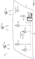
- Fig. 1 is a block diagram that schematically illustrates a sensor network 20, in accordance with an embodiment of the present invention.
- Sensors 22 (labeled S1, S2, S3, ...) are deployed at different, respective locations on a terrestrial surface 21.
- the sensors receive RF signals transmitted by either terrestrial sources 24 (labeled T1, T2) or satellite sources 26, or both.
- the locations of sensors 22, or at least of some of the sensors are known in advance, while the locations of sources 24 and/or 26 are not known a priori.
- Network 30 may comprise any suitable sort of communication network that is known in the art.
- network 30 may comprise a dedicated, wireline or wireless network.
- network 30 may comprise a public network, such as the Internet or a cellular communication network.
- controller 28 is shown and described here as a centralized unit, the functions of the controller may, additionally or alternatively, be performed in a centralized or distributed fashion by processors at different locations on network 30, including processors that are coupled to and associated with one or more of sensors 22.
- sensors 22 transmit their respective TOA data over network 30 to controller 28, without return transmissions of any sort. Return transmission may be useful in some applications, however, for conveying control, synchronization and/or navigation information, for example, from controller 28 to sensors 22.
- sensors 22 may receive and measure times of arrival of signals of other types.
- sources 24 may comprise acoustic emitters
- sensors 22 may comprise acoustic receivers, which are used in localizing the emitters using the methods described below.
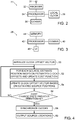
- Fig. 2 is a block diagram that schematically shows components of sensor 22, in accordance with an embodiment of the present invention.
- a receiver 32 receives and amplifies RF signals via an antenna 31 from sources 24 and/or 26.
- a local processor 34 identifies the incoming signals and measures their times of arrival, based on clock signals provided by a local clock 36. As noted earlier, the TOA measurements may be simple local measurements or differential (DTOA) measurements.
- Processor 34 transmits the TOA measurement results for the received signals from each of the relevant sources to controller 28 over network 30 via a communications interface 38. Any suitable communication protocol, either standard or proprietary, may be used for this purpose.
- local clock 36 need not be particularly accurate and is generally not synchronized with the local clocks of other sensors. Any suitable sort of oscillator, as is known in the art, may thus be used in generating the clock signal according to which processor 34 makes its TOA measurements. If one or more of sensors 22 has access to absolute-time clock, then this information can be used to propagate the absolute time among the sensors in sensor network 20 after synchronization is established.
- Fig. 3 is a block diagram that schematically shows details of synchronization controller 28, in accordance with an embodiment of the present invention.
- Controller 28 receives TOA data over network 30 via a communication interface 40.
- a processor 42 stores relevant data in a memory 44, and computes synchronization and localization results as described hereinbelow. These results may be output via a user interface (UI) 46, for example, or transmitted to sensors 22 or to other items of equipment via interface 40.
- UI user interface
- Processor 42 and the other components of controller 28 may be parts of a general-purpose computer, which is programmed in software to carry out the functions that are described herein.
- This software may be downloaded to controller 28 in electronic form, over a network, for example.
- the software may be stored in a tangible, non-transitory computer-readable medium, such as optical, magnetic, or electronic memory (which may be incorporated in memory 44).
- at least some of the functions of processor 42 may be carried out by dedicated or programmable hardware logic.
- Fig. 4 is a flow chart that schematically illustrates a method for clock synchronization and localization in sensor network 20, in accordance with an embodiment of the present invention. This method synchronizes and localizes a system of M sensors 22 and N sources 24, 26. Certain aspects will be described below initially with reference only to terrestrial sources 24, and will then be expanded to handle satellite sources 26, as well.
- controller 28 compares the new cost value to the cost value from the previous iteration, at a cost evaluation step 56. Specifically, the controller may evaluate whether the change in cost since the previous iteration is less than a certain threshold. If not, n is incremented, and control returns to step 52 for a further iteration.
- controller 28 synchronizes the clocks of sensors 22 based on the current value of the estimated clock offsets, at a synchronization step 58.
- the controller may either send actual synchronization values to the sensors, or it may simply record and apply appropriate corrections to the clock readings received from the sensors.
- the controller may also output or otherwise apply the current estimate of the source location values, at a location output step 60.
- sensors 22 are sufficiently close together (typically not more than a few tens of kilometers apart) so that ionospheric and tropospheric effects on the satellite signals can be considered to be uniform. Otherwise, measurements should be corrected by tropospheric and ionospheric correction models or measurements. If the satellite signals occupy a large bandwidth or are scattered over a wide frequency band, the ionospheric correction can be estimated accurately, as is known in the art. Alternatively or additionally, comparison of signals may be limited to measurements from sets of sensors that are close to one another, thus allowing the entire sensor set to be deployed on a wider area.
- the s -th sensor has an internal clock offset denoted by ⁇ S .
- m t s be the TOA measurement performed by the s -th sensor for the t -th source.
- q S the known coordinates vector of the sensor and the unknown coordinates vector of the source, respectively.
- ⁇ t be the unknown transmit time.
- m t s 1 c ⁇ q S ⁇ p t ⁇ + ⁇ t + ⁇ S + e t s where e t s is a random measurement error with zero mean and a standard deviation of ⁇ t s .
- ⁇ t s ⁇ t , or more precisely, the noise is assumed to be independent and identically distributed (i.i.d).
- the self-synchronized localization problem in a planar geometry, has 3 N + M - 1 unknowns: 2N unknown source coordinates, N unknown transmit times and M - 1 sensor time offsets w.r.t. the reference sensor. If all sensors receive the signals of all the sources, we have MN TOA measurements. Thus, the problem is well posed if MN ⁇ 3 N + M - 1.
- the number of equations is not smaller than the number of unknowns.
- at least two sources and five sensors are required.
- solving the above equation for two sources requires a search within a four-dimensional space.
- a possible source with known location can be a sensor that is also allowed to transmit.
- the above algorithm can be used for network-wide synchronization and localization as long as the number of measurements is not smaller than the number of unknowns.
- the set of ⁇ ' vectors satisfying the above constraints form a polyhedron in R M ⁇ 1 space.
- the measure of uncertainty of the estimation of the ⁇ vector is useful in a number of ways. As noted earlier, given a source of known location, the clock offsets are readily found at raw measurement accuracy. Therefore, if we have a subset of more than three clock offsets estimates with high certainty, we can get a good source position estimation and thus a high-certainty estimation of the clock offsets for all the sensors that received a transmission from this source.
- the Pseudo-Likelihood function which provides the likelihood of a value of ⁇ ij ⁇ ⁇ i ⁇ ⁇ j given the constraints imposed on d ( i,j ) for each sensor pair using all measurements made by the pair.
- the Pseudo-Likelihood function f ⁇ ij of ⁇ ij is defined by M t i j ⁇ min 2 m t i ⁇ m t j ⁇ x + d i j m t i ⁇ m t j ⁇ x ⁇ d i j L t i j ⁇ ⁇ 1 if x ⁇ m t i ⁇ m t j ⁇ d i j exp ⁇ M t i j 4 ⁇ 2 otherwise f ⁇ ij x ⁇ ⁇ t ⁇ T ij L t i j ⁇ ⁇ ⁇ ⁇ t ⁇ T ij L t i j where T ij is the set of sources that were measured by both sensor i and sensor j , which here include all sources.
- the ML estimator When noise is introduced, the ML estimator is such that it is not necessary to estimate the full ⁇ vector, but only its projection B ⁇ .
- Estimating B ⁇ cannot be achieved directly by using MVIE since the domain of B ⁇ has M - 1 non-singular dimensions, making its volume in always zero for any set of constraints. Therefore any inscribed ellipsoid volume will always be zero, making any volume maximization impossible.
- the MVIE only to the projection subspace defined by B . This subspace is the span of the eigenvectors of B corresponding to the unity eigenvalues.
- Program 1.3 If Program 1.3 returns the non-feasible token, then the value of ⁇ is decreased, and the solution is repeated.
- WLS weighted least squares
- G T G as a covariance matrix is conservative, since it describes the ellipsoid within which the clock offsets vector almost always lie. Therefore adding a constant factor to the matrix to convert it from a certainty ellipsoid to a covariance matrix is appropriate. Defining the constant factor as ⁇ > 1, the covariance matrix for the MVIE clock offset estimation is G T G ⁇ . Methods are known in the art for computing ⁇ to convert certainty ellipsoid to a covariance matrix of a multi-variate normal distribution, but ⁇ can also be determined empirically.
- the MVIE/ML estimator performs well under the imposed constraints.
- the MVIE/ML estimator even after only one ML iteration comes very close to the converged ML performance. This feature makes the combined MVIE/ML estimator very attractive in terms of processing time. Comparing the results of the combined MVIE/ML estimator to the known clock offset case, we observe that even in the first iteration, the penalty of not knowing the clock offsets is not very large.
- ⁇ n is on the order of the distance between the sensors (which is a highly nonlinear configuration), the MVIE/ML estimator converges successfully.
- the MVIE can also be used as a priori information in a MAP estimator.
- ML estimator cannot use measurements of sources that are received by three sensors or less, but MVIE can.
- clock bias is actually the measurement bias, meaning that it contains any propagation delays inside of the sensor.
- a sensor that has an antenna connected with a long cable will include the cable propagation time as part of the bias. In sensing systems, this effect should generally be calibrated. The method described above provides sensor self-calibration of such delays.
- the MVIE used constraints based on measurements of a source by a pair of sensors. This section will present constraints based on measurements of a source by a sensor triplet. Methods to incorporate these constraints into the MVIE will also be introduced.
- Measurement space is defined as the R 2 space ( ⁇ 01 , ⁇ 02 ).
- ⁇ ⁇ ⁇ 02 cos ⁇ ⁇ ⁇ + sin ⁇ ⁇ ⁇ tan ⁇
- the segments h 6,7 are always in the lower part of the bound, so that their tangents pose a lower bound, while h 8 is always on top, so that its tangents pose an upper bound.
- the last equation defines the relation between the bound on the DTOA measurements and the clock offsets.
- the direction of the inequality is determined by the value of ⁇ : For ⁇ ⁇ [0, ⁇ ] ⁇ [ ⁇ - ⁇ , ⁇ ] it will be ⁇ and for ⁇ ⁇ [ ⁇ + ⁇ ,2 ⁇ - ⁇ ] it will be ⁇ .
- the pseudo likelihood function f ⁇ ⁇ ksp ⁇ of ⁇ ⁇ ksp ⁇ is defined by: m ⁇ t k s p ⁇ ⁇ m t p ⁇ m t k ⁇ q 1 ⁇ m t s ⁇ m t k ⁇ x ⁇ exp ⁇ m ⁇ t k s p ⁇ ⁇ q 0 ⁇ 2 2 ⁇ ⁇ t 2 L m ⁇ t k s p ⁇ ⁇ ⁇ 1 if x ⁇ m ⁇ t k s p ⁇ ⁇ q 0 ⁇ ⁇ x otherwise f ⁇ ⁇ k , s , p , ⁇ x ⁇ ⁇ t ⁇ T ksp L m ⁇ t k s p ⁇ ⁇ ⁇ ⁇ ⁇ ⁇ ⁇ ⁇
- the direction of the inequality is determined by the value of ⁇ as before.
- the pseudo likelihood function yields the constraint ⁇ ⁇ ksp ⁇ ⁇ h ksp ⁇ w.p. 1 - ⁇ . This is a linear constraint on the clock offsets that can be incorporated into the MVIE optimization problem.
- the bounds can be derived from the elementary bounds, or the lowest feasible value can be used.
- the s -th sensor has an internal clock with offset denoted by ⁇ s and skew denoted by ⁇ s .
- m t s be the TOA measurement performed by the s -th sensor for the t -th source.
- q s , p t the known coordinate vector of the sensor and the unknown coordinate vector of the source, respectively.
- r t s ⁇ 1 c ⁇ q s ⁇ p t ⁇ is the propagation time between source t and sensor s .
- m t s ⁇ s r t s + ⁇ t + ⁇ s + e t s
- e t s is a random measurement error with zero mean and a standard deviation of ⁇ t s .
- the self-synchronized localization problem in a planar geometry, has 3 N + 2( M - 1) unknowns: 2N unknown source coordinates, N unknown transmit times, M - 1 sensor time offsets, and M -1 clock skews w.r.t. the reference sensor. If all sensors receive the signals of all the sources, there are MN TOA measurements. Thus, the problem is well posed if MN ⁇ 3N + 2( M -1).
- the cost function is minimized w.r.t.
- Controller 28 starts by collecting all measurements made by a pair of sensors k , s .
- the measurement of sensor k is given by Eq. 3.1.
- the relative clock skew may be defined as ⁇ ks ⁇ ⁇ k ⁇ s .
- the pseudo likelihood function provides the likelihood of a value of ⁇ ks given the constraints imposed by Eq. 3.32 for each sensor pair using all measurements made by the pair. Assuming all measurement noise is i.i.d and has variance of ⁇ t , the pseudo likelihood function f ⁇ ks of ⁇ ks is defined by: ddm t , p k s ⁇ dm t ks ⁇ dm p ks M t , p k s ⁇ min 2 ddm t , p k s ⁇ T t , p + 2 d k , s c ⁇ ⁇ T t , p ⁇ ⁇ ks ddm t , p k s ⁇ T t , p ⁇ 2 d k , s c ⁇ ⁇ T t , p ⁇ ⁇ ks ⁇ ⁇ ks ⁇ exp ⁇ ⁇
- T k,s is the set of source pairs that were measured by both sensor k and sensor s , which is assumed here to include all sources. It is assumed that ddm t , p k s are uncorrelated with one another, but this approximation can easily be eliminated. From the pseudo likelihood function, we obtain E[ ⁇ ks ], var [ ⁇ ks ], and ⁇ ks ⁇ ( l ks , h ks ) w.p. 1 - ⁇ .
- MVIE Maximum Volume Inscribed Ellipsoid
- the next step is to estimate the clock offset vector ⁇ .
- the above equation states that the clock skew uncertainty is amplified by the source transmit (Tx) time.
- ⁇ ks ⁇ ⁇ t 2 v ks T G ⁇ G ⁇ v ks 4 + 2 ⁇ t 2
- v ks T is a difference vector holding 1 and -1 in the k-1, s-1 rows respectively, and containing zeros elsewhere.
- the pseudo likelihood measure can be applied to give bounds on ⁇ ⁇ ks ⁇ ⁇ k ⁇ ⁇ k ⁇ ⁇ s ⁇ ⁇ s ⁇ ⁇ ⁇ k ⁇ ⁇ ⁇ s for every s,k.
- the ⁇ pseudo likelihood measure is defined as follows: d m ⁇ t i j ⁇ m ⁇ t i ⁇ m ⁇ t j M t i j ⁇ min 2 d m ⁇ t i j ⁇ x + d i j d m ⁇ t i j ⁇ x ⁇ d i j ⁇ x ⁇ exp ⁇ M t i j 2 ⁇ ij 2 L d m ⁇ t ⁇ ⁇ 1 if x ⁇ d m ⁇ t i j ⁇ d i j ⁇ x otherwise f ⁇ ⁇ ij x ⁇ ⁇ t ⁇ T ij L d m ⁇ t ⁇ ⁇ ⁇ ⁇ ⁇ t ⁇ T ij L d m ⁇ t ⁇ ⁇ ⁇ ⁇ t ⁇ T ij L d m ⁇ t
- the ⁇ vector can be estimated using the error covariance matrix approximation G ⁇ ⁇ G ⁇ ⁇ T by using MVIE centering:
- controller 28 can synchronize a sensor network with skewed, asynchronous clocks by measuring the TOA of a set of source signals.
- MVIE MVIE
- the clock offset can be measured at the time of transmission at raw measurement accuracy. If a source transmits twice without changing position, then the clock skew of the sensors that sense it can be estimated directly at the accuracy of the raw measurement. Incorporating such measurements into the system model can increase the system accuracy.
- a source with known location can also be a sensor that is allowed to transmit. Periodic sources (such as some transmitting satellites) usually have a transmission period that is very short, so that adjacent transmissions have essentially the same position.
- the MVIE estimate together with its accuracy estimation can also be used as a priori probability of the unknowns in a MAP estimator.
- the MVIE of the normalized clock offset can be estimated at a few points in time to increase accuracy if needed.
- N the total number of sources received by the sensors N ⁇ N t + N s
- the orientation of the coordinate system is set to North West Up.
- the vector r t is approximated by r t ⁇ 1 c ⁇ p t ⁇ 1 M ⁇ G p ⁇ t wherein G ⁇ 1 c q 0 q 1 ... q M ⁇ 1 T and p t is a unit vector in the direction of p t .
- the present methods use a projection of the range vector that is defined as: r ⁇ t ⁇ Br t B ⁇ I ⁇ 1 M 11 T .
- the second-order term in the Taylor expansion determines the approximation error.
- the domain of the vector r ⁇ t is part of a subspace of . Due to the structure of G , r ⁇ t resides in a two- or three-dimensional subspace of .
- the subspace will be two-dimensional for planar sensor configuration, and three-dimensional in the general case.
- the domain of p t is the three-dimensional unit half-sphere such that: p ⁇ t ⁇ z ⁇ ⁇ 0 , wherein z is the unit vector pointing up.
- This inequality holds since from any point on the surface of the earth, the intercepted signals arrive from above the horizon.
- the vector r ⁇ t is a linear transformation of p t , and therefore its domain is a linear mapping of the upper half of the unit sphere in onto , which is a half ellipsoid in .
- Singular Value Decomposition (SVD) of -BG reveals the exact shape of that half ellipsoid.
- ⁇ BG U ⁇ R 0 V T ⁇ R T H T ⁇ R 0 V T
- U and V are unitary square matrixes of size M ⁇ M , and 3 ⁇ 3 respectively
- ⁇ R is the non negative singular value diagonal matrix of size 3 ⁇ 3 at most
- R rows hold the left singular vectors related to the nonzero singular values
- the rest of the left singular vectors form the rows of H.
- the nonzero singular values define the lengths of the semi-axis of the ellipsoid, while the related left-singular vectors define the semi-axis of the ellipsoid.
- the domain of p t is a half ellipsoid.
- the plane normal is approximately aligned with the semi-axis of the ellipsoid.
- the ML estimator for terrestrial sources without clock skew was derived above for the localization of a general source using TOA measurements.
- r t is the vector of distances of the source t to all sensors
- ⁇ t is the unknown source transmission time.
- the configuration containing satellites and terrestrial sources of unknown position and transmission time fits this cost function.
- This criterion limits the search interval.
- controller 28 synchronizes the clocks of sensors 22 based on the current value of ⁇ (step 58). Depending on application requirements, the controller may either send actual synchronization values to the sensors, or it may simply record and apply appropriate corrections to the clock readings received from the sensors. The controller may also output or otherwise apply the source location values given by the current elements of r (step 60).
- controller 28 For every iteration of this algorithm, controller 28 performs N S + N T nonlinear least square optimizations. To avoid convergence of the cost function to a local minimum (rather than the true minimum corresponding to the actual clock offsets and source positions), a good initial estimate of the source locations and/or clock offsets is useful. Such an estimate can reduce the computational load considerably by reducing the number of iterations required for convergence. In tracking applications, a previous estimate may be used as a good starting point, but in the absence of a previous estimate, other information may be used.
- controller 28 can solve the original cost function using gradient methods, which are very effective.
- This equation is equivalent to finding the roots of a sixth degree polynomial.
- An efficient numerical solution for the roots can be found by seeking the eigenvalues of the companion matrix of the polynomial.
- One way to reduce the complexity in runtime is by realizing that the ⁇ values are constant as long as the sensors are static, they are needed only once, at initialization.
- Controller 28 can test which of the real solutions is the optimal one by evaluating the cost function for each possible value, thus assuring that the global optimum is chosen.
- the use of the weight matrix extends the results to include correlated measurements and can be applied to reduce the dimension of the measurement vector, as explained below.
- Controller 28 may decompose the cost function into such components in order to solve the problems of clock synchronization and satellite source direction more efficiently.
- H and R are defined above as the null and range-space projectors of BG p t .
- the two parts of the cost Q can be solved independently, thereby making the ML estimator simpler to compute. Because the measurement vectors HBm t and RBm t are uncorrelated, the estimation error covariance matrix is block diagonal. The ML estimators related to the two cost functions can thus be computed separately, as described below.
- the estimation accuracy depends only on the number of signals measured.
- the positions of sensors 22 also do not affect the estimation accuracy, as long as the sensors are confined to an area such that the linear approximation of the satellite ranges holds.
- a single source is sufficient to establish an estimation of the null space projection of the clock offsets (although this is not the case for the range space).
- Estimating the clock offsets in null space is sufficient to localize terrestrial sources with reasonable accuracy.
- sources confined to a plane can be localized if at least six sensors observe the signals, and for sources that are not in a plane at least seven sensors are required.
- sources confined to a plane can be localized if at least five sensors observe the signals, whereas for sources that are not confined to a plane, at least six sensors are required.
- R RB
- the measurement vector RBm t elements are independent and identically distributed Gaussian random variables. The mode of calculation depends on the sensor formation: If the sensors are confined to a plane, then RBr t can be any value inside an ellipse, whereas if the sensor distribution is in 3D space, RBr t is distributed on a 3D ellipsoidal half shell, which enables better accuracy.
- ⁇ R the problem of estimating ⁇ R is reduced to finding the possible centers of an ellipse of known dimensions given a set of points in the ellipse domain corrupted by noise.
- the set of possible centers can be found, for example, by calculating the mean of the points (which is guaranteed to be inside of the ellipse) and then expanding the set of possible points by propagating out from that point.
- Controller 28 can determine whether a point is in the domain of possible offsets by checking whether an elliptical disk with its center at that point include all of the measured points in its domain. Regardless of how the set of points is found, its mean can be written as ⁇ R , and its empirical covariance matrix as ⁇ R .
- estimating ⁇ R is reduced to finding the ellipsoid center given a set of points that are located on the ellipsoid half shell in the noiseless case, or are near this shell in the noisy case.
- This problem can be solved in a number of ways, including high-dimensional ML estimation, low-dimensional iterative ML estimation, and ellipsoid surface fitting.
- the high-dimensional ML estimator takes the range space cost function and minimizes it for all satellite directions p t and range-projected clock offsets ⁇ R . This is an optimization problem in 3 + 2N s dimensions which is easy to solve as long as the number of satellites is small enough.
- the low-dimensional iterative ML estimator is similar to the iterative ML algorithm described above, but is applied only to minimize the cost function with respect to satellite directions and a 3D ⁇ R vector. Each iteration solves two or three dimensions at a time and is inherently fast.
- This step can be accomplished by the Lagrange multiplier technique presented above, using R as the weighting matrix W .
- This estimation process thus comprises an averaging operation followed by an eigenvalue calculation of a 6x6 matrix. This estimator is therefore fast as long as the iteration count is reasonable.
- the surface fitting method uses the fact that an ellipsoid center is to be fitted to noisy points, which is again a 3D problem with fast convergence properties. It is based generally on techniques described by Ahn et al., in “Orthogonal Distance Fitting of Implicit Curves and Surfaces," IEEE Transactions on Pattern Analysis and Machine Intelligence, 24(5):620-638 (2002 ). This fitting method is a good approximation of the ML estimator and is relatively simple to apply in the present case since the ellipsoid to be fitted is of known shape and orientation, so the only parameters left to fit are the ellipsoid center coordinates.
- a is the proposed ellipsoid center
- x is the noisy point
- x' is the closest point to x that is on the ellipsoid centered at a
- P T P is a weighting matrix
- d i is the Euclidean distance between x i and x' i . It is easier to consider x, x' in a coordinate system that is centered at a and aligned with the eigenvectors given by the rows of R .
- the ellipsoid center estimation may be carried out using the following orthogonal distance fitting algorithm to find he ellipsoid center â:
- k ⁇ ⁇ x ′ ⁇ f x
- k , x ′ k + 1 x ′ k + ⁇ ⁇ x ′
- f x ′ 1 2 ⁇ 1 + x ′ 2 2 ⁇ 2 + x ′ 3 2 ⁇ 3 ⁇ 1 ⁇ 2 x 1 ⁇ 2 x 2 ⁇ x ′ 2 + 2 x 2 ⁇ 1 x 1 ⁇ x ′ 1 ⁇ 2 x 2 ⁇ 3 x 3 ⁇ x ′ 3 + 2 x 3 ⁇ 2 x 2 ⁇ x ′ 2
- k a ⁇ k + 1 a ⁇ k + ⁇ k ⁇ ⁇ a
- J ⁇ ⁇ d ⁇ a , and ⁇ ⁇ (0,1) is a constant that helps convergence in noisy situations.
- the above algorithm for ellipsoid center estimation requires inverting matrices only of size 3x3. Because this algorithm uses the steepest descent at the ellipsoid center update, as defined by ⁇ a, whereas the previous algorithm uses ML estimation of the center under the assumption that the satellites directions are known, the present algorithm may converge in fewer steps, although each step is a bit more complex.
- controller 28 can now establish full synchronization of sensors 22 using satellite sources 26.
- B ⁇ ⁇ ⁇ is inserted into the ML cost function: Q t ⁇ ⁇ B m t ⁇ r t ⁇ B ⁇ ⁇ ⁇ 2 , and controller 28 finds the solution that minimizes the cost for every satellite t .
- the Lagrange multipliers described above may be used for this purpose.
- controller 28 is able to synchronize a set of sensors 22 deployed over a wide area using satellites having unknown orbital parameters and time references.
- the directions to the satellites are estimated as a by-product.
- the accuracy of the synchronization is only limited by the radio bandwidth, signal/noise ratio (SNR), observation time, and the number of sources processed.
- controller 28 can establish synchronized time-based localization of terrestrial sources 24. This approach can be useful since estimating ⁇ R is more demanding, and cannot be accomplished by the above methods with fewer than three celestial signals. Moreover, this sort of localization enables estimation of the full clock offset vector B ⁇ , as explained below.
- the accuracy of the clock offset estimation for sensors 22 may be improved by considering the localization of terrestrial sources 24. After refining the clock offsets, controller 28 can improve the localizations of the terrestrial sources and continue iterating to convergence. Convergence is assured, as improving the clock offset estimation accuracy increases the accuracy of localization of the terrestrial sources and of the directions of the satellite sources, and vice versa.
- the ML estimator for B ⁇ may be derived in this case as follows:
- the error of p ⁇ t is a vector in two or three dimensions, whereas r ⁇ ⁇ is a vector in M dimensions.
- H t Bm t H t r ⁇ t + H t B ⁇ + H t Be t
- the result is a linear measurement of a projection of the sensor clock offsets vector.
- H 0 Bm 0 ⁇ r ⁇ ⁇ 0 H 1 Bm 1 ⁇ r ⁇ ⁇ 0 ⁇ H N t ⁇ 1 Bm N t ⁇ 1 ⁇ r ⁇ ⁇ N t ⁇ 1 H 0 H 1 ⁇ H N t ⁇ 1 B ⁇ + H 0 B 0 H 1 B ⁇ 0 H N t ⁇ 1 B e 0 e 1 ⁇ e N t ⁇ 1 , which is completely independent of the localization errors.
- An expression may be developed as follows for the covariance matrix of: m T ⁇ Bm 0 ⁇ r ⁇ ⁇ 0 T , Bm 1 ⁇ r ⁇ ⁇ 1 T , ... , Bm N T ⁇ 1 ⁇ r ⁇ ⁇ N T ⁇ 1 T T .
- controller 28 may again re-estimate the locations of terrestrial sources 24, and repeat until convergence as described above. in some embodiments it is possible to skip the steps that use RBm t and return, or alternately do the final refinement using gradient methods on the original cost function and measurement vector.
- the problem of navigation of a moving object in system 20 is equivalent to assuming that a sensor of unknown position is added to the network. This addition does not change the form of the measurement model. Considering only celestial sources, for example, the only difference is that now one row of the G matrix is unknown, and another clock offset is added.
- Bm t ⁇ B G 0 p ⁇ t + B 0 s T p ⁇ t + ⁇ 0 + B 0 ⁇ s + Be t
- controller 28 can use gradient methods to find the optimal point in terms of ML cost.
- the problem framed above can be extended to the case of multiple sensors of unknown position by solving the LS estimation for each of these sensors.
- the ML estimator can use these initial estimates to find the optimum of the full ML cost, and in so doing also refine the estimates of the known sensors clock offsets and the satellite directions.
- Terrestrial sources can also be incorporated into the ML cost function.
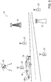
- Fig. 5 is a schematic, pictorial illustration showing a navigation system 70 based on a network of sensors 22, in accordance with an embodiment of the present invention.
- the sensor network in this example is deployed in an airport, with controller 28 housed in a control center 72.
- Airplanes 74 are also allowed to carry sensors 76 (or to be able to transmit or reflect a signal that sensors 22 can detect).
- Sources that can be used by the system include ground sources 24 (such as beacons, radar signals), aerial sources (airplane beacons 76), and sky sources (satellites 26).
- System 70 will be generally immune to jamming and spoofing, unlike GNSS systems.
- the arrangement shown in Fig. 5 enables accurate airplane navigation, and the measurements of airplane sensors 76 can also be used to improve system accuracy and integrity even further using the methods described above. As noted earlier, the readings of sensor 76 can be used to improve clock synchronization, terrestrial source localization and satellite direction accuracy. Navigation is still possible even if only terrestrial sources are present, although the processing required is typically more complex.
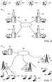
- FIG. 6 is a schematic, pictorial illustration of a computer system 80 with sensor-based synchronization, in accordance with an embodiment of the present invention.
- System 80 may comprise, for example, a computerized securities trading system, in which servers 82 are connected by a network 84 and user sensors 22 in accurately synchronizing their respective clocks based on signals from satellite sources 26.
- servers 82 use sensors 22 to implement spoof-proof and jamming-proof time-stamping, based on the methods of clock synchronization that are described above.
- time transfer is enabled without the use of GNSS, the absolute time can be maintained by all servers 82, which are unlikely to be GNSS-jammed at the same time, or the servers as a group could perform time holdover until the total jamming has passed.
- System 80 is thus able to maintain normal operation even under jamming attacks and to detect and reject attempts at source spoofing quickly and robustly.
- Fig. 7 is a schematic, pictorial illustration of a communication system 90 with sensor-based synchronization, in accordance with an embodiment of the present invention.
- System 90 comprises multiple base stations (BS) 92, which are coupled via a network 94 to controller 28.
- the base stations collect TOA information gathered by user equipment 96, and controller 28 (or distributed controllers in base stations 92) uses this information in synchronizing the base station clocks.
- System 90 differs from the embodiments described above in that the positions of the sources (base stations 92) are known precisely, while the positions of the sensors (user equipment 96) may not be known accurately. Clock synchronization is accomplished, however, substantially as described above.
- the precise synchronization that is achieved in system 90 can be used in various ways to improve network performance, such as reducing interference, increasing network capacity or bits per Hz, improving resource allocation, enabling Cooperative Multipoint (CoMP) transmission in small and macrocell deployments, and supporting time-based localization techniques such as OTDOA (observed time difference of arrival), and UTDOA.
- CoMP Cooperative Multipoint
- clock synchronization in the system can be implemented as follows:
- UTDOA Uplink TDOA
- LMUs Location Measurement Units
- the LMU can be an integral part of the base station or a separate unit, installed on the base station or in another position.
- the emitters are the user equipment (UE), and the LMUs are considered the sensors of known position.
- the LMUs clocks are synchronized, while the UE locations are also resolved.
- the base stations and LMUs are also synchronized, enabling all of the benefits stated above and eliminating the need for a dedicated external synchronization unit in each LMU.
- sensors are used to gather information on the environment, and the locations of the sensors need to be determined (as in the case of Real Time Location Services, for example).
- These environmental sensors may be regarded as "sources” in the context of this embodiment, and localization of these sensors may be achieved based solely on the signals that they emit.
- the sensor measurements of these signals constitute the information gathered by the sensors that is relayed to a central node, so that no special transmissions are required for achieving sensor localization.
- synchronization may be the major interest and not localization. This situation can arise when, for example, a wireless network needs to manage wakeup times of its nodes.
- An embodiment of the present invention provides a good solution for such cases, since emitters are usually present in any environment. Thus, even if only pairwise distances of the sensors are known, synchronization can be achieved to some extent.
- the techniques described herein can be used to check whether an existing system is synchronized and calibrated properly with respect to time offsets and skews, i.e., to detect the occurrence of synchronization faults. If the clock offsets and skews derived using the methods described above do not match those in the existing system, there may be a malfunction in the hardware or software of the existing system. In this case, the time offset and skew of the system can be recalibrated based on the synchronization described by the above methods, and this synchronization can also be used to provide a backup clock or even a set of such clocks for the system, thus affording maximal availability and reliability.
Landscapes
- Engineering & Computer Science (AREA)
- Radar, Positioning & Navigation (AREA)
- Remote Sensing (AREA)
- Physics & Mathematics (AREA)
- General Physics & Mathematics (AREA)
- Computer Networks & Wireless Communication (AREA)
- Signal Processing (AREA)
- Health & Medical Sciences (AREA)
- Computing Systems (AREA)
- General Health & Medical Sciences (AREA)
- Medical Informatics (AREA)
- Position Fixing By Use Of Radio Waves (AREA)
Claims (15)
- Verfahren für einen Senderbetrieb, das umfasst:Errichten eines Netzwerks von Quellen (24, 26), wobei die Quellen jeweilige Takte aufweisen, die nicht gegenseitig synchronisiert sind;Senden von jeweiligen Signalen von mindestens einer Gruppe der Quellen zu Zeiten, die gemäß den jeweiligen Takten der Quellen (24, 26) bestimmt werden;Bereitstellen von Ortsinformationen mit jeweiligen Quellenorten der Quellen;Empfangen von aufgezeichneten Ankunftszeiten der gesendeten Signale von einer Vielzahl von Sensoren (22);Berechnen von Synchronisationswerten als Funktion der Quellenorte und der empfangenen aufgezeichneten Ankunftszeiten von den Sensoren (22); undSynchronisieren der jeweiligen Takte der Quellen (24, 26) auf der Basis der berechneten Synchronisationswerte,wobei das Verfahren dadurch gekennzeichnet ist, dass:das Empfangen der aufgezeichneten Ankunftszeiten der gesendeten Signale das Empfangen der aufgezeichneten Ankunftszeiten der gesendeten Signale, die an den Sensoren ankommen, von einer Vielzahl von Sensoren (22) an unbekannten Orten umfasst, unddas Berechnen der Synchronisationswerte das Berechnen von Synchronisationswerten der Quellen (24, 26) als Funktion der empfangenen aufgezeichneten Ankunftszeiten von den Sensoren (22) und der Quellenorte umfasst.
- Verfahren nach Anspruch 1, wobei das Netzwerk von Quellen Basisstationen (92) in einem zellularen Kommunikationsnetzwerk umfasst, und die Sensoren ein Benutzergerät (96) im zellularen Kommunikationsnetz umfassen, und wobei das Synchronisieren der jeweiligen Takte das Synchronisieren des Betriebs der Basisstationen (92) auf der Basis der durch das Benutzergerät (96) empfangenen Signale umfasst.
- Verfahren nach Anspruch 1, wobei das Synchronisieren der jeweiligen Takte das Abschätzen von Versätzen und Verzerrungen zwischen den jeweiligen Takten umfasst.
- Verfahren nach Anspruch 1, wobei das Verfahren das Berechnen der Sensororte auf der Basis der Quellenorte und der aufgezeichneten Ankunftszeiten umfasst.
- Verfahren nach Anspruch 4, wobei das Berechnen der Sensororte das Anwenden einer Schätzfunktion auf einen Satz von Gleichungen in Bezug auf die aufgezeichneten Ankunftszeiten und die Quellen- und Sensororte umfasst.
- Verfahren nach Anspruch 5, wobei das Anwenden der Schätzfunktion das Anwenden eines iterativen Optimierungsprozesses auf den Satz der Gleichungen umfasst.
- Verfahren nach Anspruch 6, wobei das Anwenden des iterativen Optimierungsprozesses das Durchführen einer konvexen Optimierung umfasst.
- Verfahren nach Anspruch 1 und mit dem Detektieren eines Fehlers im Netzwerk auf der Basis der Ortsinformationen und der aufgezeichneten Ankunftszeiten.
- Netzwerksystem, das umfasst:ein Netzwerk von Quellen (24, 26), die jeweilige Takte umfassen, die nicht gegenseitig synchronisiert sind, und die dazu ausgelegt sind, zu Zeiten, die gemäß den jeweiligen Takten bestimmt werden, von mindestens einer Gruppe der Quellen jeweilige Signale zu senden; undeinen Prozessor (28), der dazu ausgelegt ist, aufgezeichnete Ankunftszeiten der gesendeten Signale von einer Vielzahl von Sensoren (22) zu empfangen und Synchronisationswerte als Funktion der empfangenen aufgezeichneten Ankunftszeiten von den Sensoren und Ortsinformationen mit jeweiligen Quellenorten der Quellen zu berechnen, um die jeweiligen Takte zu synchronisieren;wobei das System dadurch gekennzeichnet ist, dass:das Empfangen der aufgezeichneten Ankunftszeiten der gesendeten Signale das Empfangen der aufgezeichneten Ankunftszeiten der gesendeten Signale, die an den Sensoren ankommen, von einer Vielzahl von Sensoren (22) an unbekannten Orten umfasst; undder Prozessor die Synchronisationswerte der Quellen als Funktion der Orte der Quellen (24, 26) und der empfangenen aufgezeichneten Ankunftszeiten von den Sensoren (22) berechnet.
- System nach Anspruch 9, wobei das Netzwerk von Quellen Basisstationen in einem zellularen Kommunikationsnetzwerk umfasst und die Sensoren ein Benutzergerät im zellularen Kommunikationsnetzwerk umfassen, und wobei der Prozessor dazu ausgelegt ist, den Betrieb der Basisstationen auf der Basis der Signale, die durch das Benutzergerät empfangen werden, zu synchronisieren.
- System nach Anspruch 10, wobei das zellulare Kommunikationsnetzwerk gemäß einem Standard der Langzeitentwicklungs- (LTE) Familie von Standards arbeitet und wobei das Benutzergerät dazu ausgelegt ist, Messungen der beobachteten Ankunftszeitdifferenz (OTDOA) auf der Basis der von den Basisstationen empfangenen Signale durchzuführen, und der Prozessor dazu ausgelegt ist, mindestens eines des Synchronisierens des Betriebs der Basisstationen und des Auffindens von Orten des Benutzergeräts auf der Basis der OTDOA-Messungen durchzuführen.
- System nach Anspruch 9, wobei der Prozessor dazu ausgelegt ist, Versätze und Verzerrungen zwischen den jeweiligen Takten abzuschätzen.
- System nach Anspruch 9, wobei der Prozessor dazu ausgelegt ist, die Sensororte auf der Basis der Quellenorte und der aufgezeichneten Ankunftszeiten zu berechnen.
- Computersoftwareprodukt mit einem nichtflüchtigen computerlesbaren Medium, in dem Programmbefehle gespeichert sind, wobei die Befehle, wenn sie durch einen Prozessor (28) ausgeführt werden, bewirken, dass das Verfahren, wie in Anspruch 1 definiert, im Netzwerksystem nach Anspruch 9 durchgeführt wird.
- Produkt nach Anspruch 14, wobei die Befehle bewirken, dass der Computer die Sensororte auf der Basis der Quellenorte und der aufgezeichneten Ankunftszeiten berechnet.
Applications Claiming Priority (3)
| Application Number | Priority Date | Filing Date | Title |
|---|---|---|---|
| US201261617186P | 2012-03-29 | 2012-03-29 | |
| US201361755485P | 2013-01-23 | 2013-01-23 | |
| PCT/IB2013/052020 WO2013144760A1 (en) | 2012-03-29 | 2013-03-14 | Localization, synchronization and navigation using passive sensor networks |
Publications (3)
| Publication Number | Publication Date |
|---|---|
| EP2831614A1 EP2831614A1 (de) | 2015-02-04 |
| EP2831614A4 EP2831614A4 (de) | 2015-12-09 |
| EP2831614B1 true EP2831614B1 (de) | 2019-09-11 |
Family
ID=49258332
Family Applications (1)
| Application Number | Title | Priority Date | Filing Date |
|---|---|---|---|
| EP13768637.4A Active EP2831614B1 (de) | 2012-03-29 | 2013-03-14 | Lokalisierung, synchronisation und navigation unter verwendung passiver sensornetzwerke |
Country Status (3)
| Country | Link |
|---|---|
| US (2) | US11140645B2 (de) |
| EP (1) | EP2831614B1 (de) |
| WO (1) | WO2013144760A1 (de) |
Families Citing this family (11)
| Publication number | Priority date | Publication date | Assignee | Title |
|---|---|---|---|---|
| US9144055B2 (en) * | 2013-10-15 | 2015-09-22 | Qualcomm Incorporated | Method and apparatus for asynchrosous positioning of wireless base stations |
| CN106797247B (zh) * | 2014-09-25 | 2019-05-31 | 瑞典爱立信有限公司 | 用于促进网络中的定时同步的方法和网络节点 |
| WO2016067080A1 (en) * | 2014-10-31 | 2016-05-06 | Telefonaktiebolaget L M Ericsson (Publ) | Methods and systems for synchronizing a communication node in a communication network |
| WO2016151571A2 (en) * | 2015-03-25 | 2016-09-29 | Pdp-Technologies Ltd. | System for mapping electromagnetic discharge fields |
| US11550024B2 (en) | 2016-09-20 | 2023-01-10 | Deeyook Location Technologies Ltd. | Interferometric location sensing |
| US11215688B2 (en) | 2016-09-20 | 2022-01-04 | Deeyook Location Technologies Ltd. | Identifying angle of departure of multi-antenna transmitters |
| CN107367710B (zh) * | 2017-07-18 | 2020-08-11 | 电子科技大学 | 一种基于时延和多普勒的分布式自适应粒子滤波直接跟踪定位方法 |
| CN110999426B (zh) * | 2017-08-08 | 2022-05-13 | Lg电子株式会社 | 执行测量的方法和执行测量的终端 |
| CN111830463B (zh) * | 2020-06-02 | 2023-02-21 | 广州南方卫星导航仪器有限公司 | 一种基于tdoa的定位系统、方法及存储介质 |
| WO2023110066A1 (en) * | 2021-12-15 | 2023-06-22 | Huawei Technologies Co., Ltd. | Apparatus, system and method for dtoa localization |
| WO2023192190A1 (en) * | 2022-03-30 | 2023-10-05 | Commscope Technologies Llc | Systems and methods for geolocation of user equipment |
Family Cites Families (28)
| Publication number | Priority date | Publication date | Assignee | Title |
|---|---|---|---|---|
| US5642069A (en) * | 1994-04-26 | 1997-06-24 | Unisys Corporation | Clock signal loss detection and recovery apparatus in multiple clock signal system |
| US5884214A (en) * | 1996-09-06 | 1999-03-16 | Snaptrack, Inc. | GPS receiver and method for processing GPS signals |
| US6522890B2 (en) | 1995-12-22 | 2003-02-18 | Cambridge Positioning Systems, Ltd. | Location and tracking system |
| US6064809A (en) | 1998-06-05 | 2000-05-16 | The Board Of Trustees Of The University Of Illinois | Fast model predictive ellipsoid control process |
| US6856945B2 (en) * | 2000-12-04 | 2005-02-15 | Tensorcomm, Inc. | Method and apparatus for implementing projections in singal processing applications |
| US6859747B2 (en) | 2001-04-26 | 2005-02-22 | Siemens Energy & Automation, Inc. | Method and apparatus for self-calibrating a motion control system |
| US7043651B2 (en) * | 2001-09-18 | 2006-05-09 | Nortel Networks Limited | Technique for synchronizing clocks in a network |
| US6912178B2 (en) | 2002-04-15 | 2005-06-28 | Polycom, Inc. | System and method for computing a location of an acoustic source |
| WO2005002100A1 (en) | 2003-06-30 | 2005-01-06 | Koninklijke Philips Electronics N.V. | High accuracy network clock synchronization |
| US7190271B2 (en) | 2003-11-07 | 2007-03-13 | Wherenet Corp | Location system and method that achieves time synchronized network performance using unsynchronized receiver clocks |
| US20050175038A1 (en) * | 2004-01-12 | 2005-08-11 | John Carlson | Method and apparatus for synchronizing wireless location servers |
| WO2006069067A2 (en) * | 2004-12-20 | 2006-06-29 | Sensicast Systems | Method for reporting and accumulating data in a wireless communication network |
| US7970574B2 (en) * | 2005-06-22 | 2011-06-28 | The Board Of Trustees Of The Leland Stanford Jr. University | Scalable sensor localization for wireless sensor networks |
| US7714862B1 (en) * | 2005-12-30 | 2010-05-11 | At & T Intellectual Property Ii, L.P. | Dig-Cola: directed graph layout through constrained energy minimization |
| US9274207B2 (en) * | 2006-02-01 | 2016-03-01 | Zih Corp. | System and method for determining signal source location in wireless local area network |
| WO2007124300A2 (en) | 2006-04-21 | 2007-11-01 | Sensis Corporation | A system and method for multilaterating a position of a target using mobile remote receiving units |
| US8344949B2 (en) * | 2008-03-31 | 2013-01-01 | Golba Llc | Wireless positioning approach using time-delay of signals with a known transmission pattern |
| DE102007043649B4 (de) * | 2007-09-13 | 2012-03-22 | Siemens Ag | Verfahren zur Erhöhung der Ortungsgenauigkeit unsynchronisierter Funkteilnehmer |
| CN101359238B (zh) * | 2008-09-02 | 2012-01-18 | 中兴通讯股份有限公司 | 一种多核系统的时间同步方法及系统 |
| US8436768B2 (en) | 2008-12-30 | 2013-05-07 | Trueposition, Inc. | Diversity time and frequency location receiver |
| US8320489B2 (en) * | 2009-02-20 | 2012-11-27 | Wisconsin Alumni Research Foundation | Determining channel coefficients in a multipath channel |
| WO2011016806A1 (en) * | 2009-08-05 | 2011-02-10 | Andrew Llc | System and method for hybrid location in a umts network |
| US8344948B2 (en) * | 2010-03-29 | 2013-01-01 | Xsens Holding B.V. | Positioning system calibration |
| US8810452B2 (en) | 2010-05-24 | 2014-08-19 | Trueposition, Inc. | Network location and synchronization of peer sensor stations in a wireless geolocation network |
| US9091746B2 (en) | 2010-07-01 | 2015-07-28 | Qualcomm Incorporated | Determination of positions of wireless transceivers to be added to a wireless communication network |
| EP2420855A1 (de) | 2010-08-20 | 2012-02-22 | EPFL Ecole Polytechnique Fédérale de Lausanne | Positionierungssystem und zugehöriges Kalibrierungsverfahren |
| US9237541B2 (en) * | 2011-03-31 | 2016-01-12 | Telefonaktiebolaget L M Ericsson (Publ) | Methods and arrangements for estimating timing offset differences in a cellular network |
| US8787944B2 (en) * | 2011-08-18 | 2014-07-22 | Rivada Research, Llc | Method and system for providing enhanced location based information for wireless handsets |
-
2013
- 2013-03-14 EP EP13768637.4A patent/EP2831614B1/de active Active
- 2013-03-14 US US14/388,808 patent/US11140645B2/en active Active
- 2013-03-14 WO PCT/IB2013/052020 patent/WO2013144760A1/en active Application Filing
-
2021
- 2021-10-04 US US17/492,773 patent/US20220039036A1/en active Pending
Non-Patent Citations (1)
| Title |
|---|
| None * |
Also Published As
| Publication number | Publication date |
|---|---|
| EP2831614A4 (de) | 2015-12-09 |
| EP2831614A1 (de) | 2015-02-04 |
| WO2013144760A1 (en) | 2013-10-03 |
| US11140645B2 (en) | 2021-10-05 |
| US20150092766A1 (en) | 2015-04-02 |
| US20220039036A1 (en) | 2022-02-03 |
Similar Documents
| Publication | Publication Date | Title |
|---|---|---|
| US20220039036A1 (en) | Localization, synchronization and navigation using passive sensor networks | |
| Buehrer et al. | Collaborative sensor network localization: Algorithms and practical issues | |
| Tomic et al. | Distributed algorithm for target localization in wireless sensor networks using RSS and AoA measurements | |
| Yan et al. | Review of range-based positioning algorithms | |
| US10338193B2 (en) | Apparatus and method for RSS/AoA target 3-D localization in wireless networks | |
| US10107891B1 (en) | Wireless signal localization and collection from an airborne symmetric line array network | |
| WO2015126499A2 (en) | Systems and methods for gnss snr probabilistic localization and 3-d mapping | |
| EP2356480A1 (de) | System und verfahren für mehrfachbereichsschätzungsort | |
| US11061104B2 (en) | Method and apparatus for positioning with wireless signals | |
| US9720071B2 (en) | Mitigating effects of multipath during position computation | |
| Yang et al. | Optimal sensor placement for source tracking under synchronization offsets and sensor location errors with distance-dependent noises | |
| Meles et al. | Measurement based performance evaluation of drone self-localization using AoA of cellular signals | |
| US11218886B2 (en) | Apparatus and method for 3-D network localization | |
| Famili et al. | OFDRA: Optimal Femtocell Deployment for Accurate Indoor Positioning of RIS-Mounted AVs | |
| Wang et al. | A 3D indoor positioning method of wireless network with single base station in multipath environment | |
| Jiexin et al. | Combination of land-based and satellite-based OTH geolocations using differentiable exact penalty method | |
| Naseri et al. | Cooperative joint synchronization and localization using time delay measurements | |
| Mwila et al. | An efficient approach to node localisation and tracking in wireless sensor networks | |
| Foo et al. | A relative-localization algorithm using incomplete pairwise distance measurements for underwater applications | |
| Cheng et al. | Ground User Localization in UAV-based Wireless Networks: From Channel Characterization to System Design | |
| Jean et al. | Synchronization via arbitrary satellite signals | |
| Mwila et al. | The use of antenna radiation pattern in node localisation algorithms for wireless sensor networks | |
| Du et al. | Indoor Vehicle Positioning for MIMO-OFDM WIFI Systems via Rearranged Sparse Bayesian Learning | |
| Verma et al. | Localization via the received signal strength gradient at lower VHF | |
| Deng et al. | Geolocation of a known altitude target using tdoa and GROA in the presence of receiver location uncertainty |
Legal Events
| Date | Code | Title | Description |
|---|---|---|---|
| PUAI | Public reference made under article 153(3) epc to a published international application that has entered the european phase |
Free format text: ORIGINAL CODE: 0009012 |
|
| 17P | Request for examination filed |
Effective date: 20141024 |
|
| AK | Designated contracting states |
Kind code of ref document: A1 Designated state(s): AL AT BE BG CH CY CZ DE DK EE ES FI FR GB GR HR HU IE IS IT LI LT LU LV MC MK MT NL NO PL PT RO RS SE SI SK SM TR |
|
| AX | Request for extension of the european patent |
Extension state: BA ME |
|
| DAX | Request for extension of the european patent (deleted) | ||
| RAP1 | Party data changed (applicant data changed or rights of an application transferred) |
Owner name: SULU NETWORKS LTD. |
|
| RA4 | Supplementary search report drawn up and despatched (corrected) |
Effective date: 20151106 |
|
| RIC1 | Information provided on ipc code assigned before grant |
Ipc: G01S 5/06 20060101ALI20151102BHEP Ipc: G01S 5/10 20060101ALI20151102BHEP Ipc: G01S 5/02 20100101ALI20151102BHEP Ipc: G01S 19/21 20100101AFI20151102BHEP |
|
| STAA | Information on the status of an ep patent application or granted ep patent |
Free format text: STATUS: EXAMINATION IS IN PROGRESS |
|
| 17Q | First examination report despatched |
Effective date: 20170526 |
|
| GRAP | Despatch of communication of intention to grant a patent |
Free format text: ORIGINAL CODE: EPIDOSNIGR1 |
|
| STAA | Information on the status of an ep patent application or granted ep patent |
Free format text: STATUS: GRANT OF PATENT IS INTENDED |
|
| INTG | Intention to grant announced |
Effective date: 20181203 |
|
| GRAS | Grant fee paid |
Free format text: ORIGINAL CODE: EPIDOSNIGR3 |
|
| GRAA | (expected) grant |
Free format text: ORIGINAL CODE: 0009210 |
|
| STAA | Information on the status of an ep patent application or granted ep patent |
Free format text: STATUS: THE PATENT HAS BEEN GRANTED |
|
| AK | Designated contracting states |
Kind code of ref document: B1 Designated state(s): AL AT BE BG CH CY CZ DE DK EE ES FI FR GB GR HR HU IE IS IT LI LT LU LV MC MK MT NL NO PL PT RO RS SE SI SK SM TR |
|
| REG | Reference to a national code |
Ref country code: GB Ref legal event code: FG4D |
|
| REG | Reference to a national code |
Ref country code: CH Ref legal event code: EP |
|
| REG | Reference to a national code |
Ref country code: AT Ref legal event code: REF Ref document number: 1179160 Country of ref document: AT Kind code of ref document: T Effective date: 20190915 |
|
| REG | Reference to a national code |
Ref country code: DE Ref legal event code: R096 Ref document number: 602013060402 Country of ref document: DE Ref country code: IE Ref legal event code: FG4D |
|
| REG | Reference to a national code |
Ref country code: CH Ref legal event code: NV Representative=s name: DENNEMEYER AG, CH |
|
| REG | Reference to a national code |
Ref country code: NL Ref legal event code: FP |
|
| REG | Reference to a national code |
Ref country code: SE Ref legal event code: TRGR |
|
| REG | Reference to a national code |
Ref country code: LT Ref legal event code: MG4D |
|
| PG25 | Lapsed in a contracting state [announced via postgrant information from national office to epo] |
Ref country code: NO Free format text: LAPSE BECAUSE OF FAILURE TO SUBMIT A TRANSLATION OF THE DESCRIPTION OR TO PAY THE FEE WITHIN THE PRESCRIBED TIME-LIMIT Effective date: 20191211 Ref country code: HR Free format text: LAPSE BECAUSE OF FAILURE TO SUBMIT A TRANSLATION OF THE DESCRIPTION OR TO PAY THE FEE WITHIN THE PRESCRIBED TIME-LIMIT Effective date: 20190911 Ref country code: BG Free format text: LAPSE BECAUSE OF FAILURE TO SUBMIT A TRANSLATION OF THE DESCRIPTION OR TO PAY THE FEE WITHIN THE PRESCRIBED TIME-LIMIT Effective date: 20191211 Ref country code: LT Free format text: LAPSE BECAUSE OF FAILURE TO SUBMIT A TRANSLATION OF THE DESCRIPTION OR TO PAY THE FEE WITHIN THE PRESCRIBED TIME-LIMIT Effective date: 20190911 |
|
| PG25 | Lapsed in a contracting state [announced via postgrant information from national office to epo] |
Ref country code: LV Free format text: LAPSE BECAUSE OF FAILURE TO SUBMIT A TRANSLATION OF THE DESCRIPTION OR TO PAY THE FEE WITHIN THE PRESCRIBED TIME-LIMIT Effective date: 20190911 Ref country code: AL Free format text: LAPSE BECAUSE OF FAILURE TO SUBMIT A TRANSLATION OF THE DESCRIPTION OR TO PAY THE FEE WITHIN THE PRESCRIBED TIME-LIMIT Effective date: 20190911 Ref country code: RS Free format text: LAPSE BECAUSE OF FAILURE TO SUBMIT A TRANSLATION OF THE DESCRIPTION OR TO PAY THE FEE WITHIN THE PRESCRIBED TIME-LIMIT Effective date: 20190911 Ref country code: GR Free format text: LAPSE BECAUSE OF FAILURE TO SUBMIT A TRANSLATION OF THE DESCRIPTION OR TO PAY THE FEE WITHIN THE PRESCRIBED TIME-LIMIT Effective date: 20191212 Ref country code: ES Free format text: LAPSE BECAUSE OF FAILURE TO SUBMIT A TRANSLATION OF THE DESCRIPTION OR TO PAY THE FEE WITHIN THE PRESCRIBED TIME-LIMIT Effective date: 20190911 |
|
| REG | Reference to a national code |
Ref country code: AT Ref legal event code: MK05 Ref document number: 1179160 Country of ref document: AT Kind code of ref document: T Effective date: 20190911 |
|
| PG25 | Lapsed in a contracting state [announced via postgrant information from national office to epo] |
Ref country code: IT Free format text: LAPSE BECAUSE OF FAILURE TO SUBMIT A TRANSLATION OF THE DESCRIPTION OR TO PAY THE FEE WITHIN THE PRESCRIBED TIME-LIMIT Effective date: 20190911 Ref country code: RO Free format text: LAPSE BECAUSE OF FAILURE TO SUBMIT A TRANSLATION OF THE DESCRIPTION OR TO PAY THE FEE WITHIN THE PRESCRIBED TIME-LIMIT Effective date: 20190911 Ref country code: PT Free format text: LAPSE BECAUSE OF FAILURE TO SUBMIT A TRANSLATION OF THE DESCRIPTION OR TO PAY THE FEE WITHIN THE PRESCRIBED TIME-LIMIT Effective date: 20200113 Ref country code: PL Free format text: LAPSE BECAUSE OF FAILURE TO SUBMIT A TRANSLATION OF THE DESCRIPTION OR TO PAY THE FEE WITHIN THE PRESCRIBED TIME-LIMIT Effective date: 20190911 Ref country code: EE Free format text: LAPSE BECAUSE OF FAILURE TO SUBMIT A TRANSLATION OF THE DESCRIPTION OR TO PAY THE FEE WITHIN THE PRESCRIBED TIME-LIMIT Effective date: 20190911 Ref country code: AT Free format text: LAPSE BECAUSE OF FAILURE TO SUBMIT A TRANSLATION OF THE DESCRIPTION OR TO PAY THE FEE WITHIN THE PRESCRIBED TIME-LIMIT Effective date: 20190911 |
|
| PG25 | Lapsed in a contracting state [announced via postgrant information from national office to epo] |
Ref country code: CZ Free format text: LAPSE BECAUSE OF FAILURE TO SUBMIT A TRANSLATION OF THE DESCRIPTION OR TO PAY THE FEE WITHIN THE PRESCRIBED TIME-LIMIT Effective date: 20190911 Ref country code: SM Free format text: LAPSE BECAUSE OF FAILURE TO SUBMIT A TRANSLATION OF THE DESCRIPTION OR TO PAY THE FEE WITHIN THE PRESCRIBED TIME-LIMIT Effective date: 20190911 Ref country code: IS Free format text: LAPSE BECAUSE OF FAILURE TO SUBMIT A TRANSLATION OF THE DESCRIPTION OR TO PAY THE FEE WITHIN THE PRESCRIBED TIME-LIMIT Effective date: 20200224 Ref country code: SK Free format text: LAPSE BECAUSE OF FAILURE TO SUBMIT A TRANSLATION OF THE DESCRIPTION OR TO PAY THE FEE WITHIN THE PRESCRIBED TIME-LIMIT Effective date: 20190911 |
|
| REG | Reference to a national code |
Ref country code: DE Ref legal event code: R097 Ref document number: 602013060402 Country of ref document: DE |
|
| PLBE | No opposition filed within time limit |
Free format text: ORIGINAL CODE: 0009261 |
|
| STAA | Information on the status of an ep patent application or granted ep patent |
Free format text: STATUS: NO OPPOSITION FILED WITHIN TIME LIMIT |
|
| PG2D | Information on lapse in contracting state deleted |
Ref country code: IS |
|
| PG25 | Lapsed in a contracting state [announced via postgrant information from national office to epo] |
Ref country code: DK Free format text: LAPSE BECAUSE OF FAILURE TO SUBMIT A TRANSLATION OF THE DESCRIPTION OR TO PAY THE FEE WITHIN THE PRESCRIBED TIME-LIMIT Effective date: 20190911 Ref country code: IS Free format text: LAPSE BECAUSE OF FAILURE TO SUBMIT A TRANSLATION OF THE DESCRIPTION OR TO PAY THE FEE WITHIN THE PRESCRIBED TIME-LIMIT Effective date: 20200112 |
|
| 26N | No opposition filed |
Effective date: 20200615 |
|
| PG25 | Lapsed in a contracting state [announced via postgrant information from national office to epo] |
Ref country code: SI Free format text: LAPSE BECAUSE OF FAILURE TO SUBMIT A TRANSLATION OF THE DESCRIPTION OR TO PAY THE FEE WITHIN THE PRESCRIBED TIME-LIMIT Effective date: 20190911 |
|
| PG25 | Lapsed in a contracting state [announced via postgrant information from national office to epo] |
Ref country code: MC Free format text: LAPSE BECAUSE OF FAILURE TO SUBMIT A TRANSLATION OF THE DESCRIPTION OR TO PAY THE FEE WITHIN THE PRESCRIBED TIME-LIMIT Effective date: 20190911 |
|
| REG | Reference to a national code |
Ref country code: BE Ref legal event code: MM Effective date: 20200331 |
|
| PG25 | Lapsed in a contracting state [announced via postgrant information from national office to epo] |
Ref country code: LU Free format text: LAPSE BECAUSE OF NON-PAYMENT OF DUE FEES Effective date: 20200314 |
|
| PG25 | Lapsed in a contracting state [announced via postgrant information from national office to epo] |
Ref country code: IE Free format text: LAPSE BECAUSE OF NON-PAYMENT OF DUE FEES Effective date: 20200314 |
|
| PG25 | Lapsed in a contracting state [announced via postgrant information from national office to epo] |
Ref country code: BE Free format text: LAPSE BECAUSE OF NON-PAYMENT OF DUE FEES Effective date: 20200331 |
|
| PG25 | Lapsed in a contracting state [announced via postgrant information from national office to epo] |
Ref country code: TR Free format text: LAPSE BECAUSE OF FAILURE TO SUBMIT A TRANSLATION OF THE DESCRIPTION OR TO PAY THE FEE WITHIN THE PRESCRIBED TIME-LIMIT Effective date: 20190911 Ref country code: MT Free format text: LAPSE BECAUSE OF FAILURE TO SUBMIT A TRANSLATION OF THE DESCRIPTION OR TO PAY THE FEE WITHIN THE PRESCRIBED TIME-LIMIT Effective date: 20190911 Ref country code: CY Free format text: LAPSE BECAUSE OF FAILURE TO SUBMIT A TRANSLATION OF THE DESCRIPTION OR TO PAY THE FEE WITHIN THE PRESCRIBED TIME-LIMIT Effective date: 20190911 |
|
| PG25 | Lapsed in a contracting state [announced via postgrant information from national office to epo] |
Ref country code: MK Free format text: LAPSE BECAUSE OF FAILURE TO SUBMIT A TRANSLATION OF THE DESCRIPTION OR TO PAY THE FEE WITHIN THE PRESCRIBED TIME-LIMIT Effective date: 20190911 |
|
| PGFP | Annual fee paid to national office [announced via postgrant information from national office to epo] |
Ref country code: FR Payment date: 20230324 Year of fee payment: 11 Ref country code: FI Payment date: 20230321 Year of fee payment: 11 |
|
| PGFP | Annual fee paid to national office [announced via postgrant information from national office to epo] |
Ref country code: SE Payment date: 20230314 Year of fee payment: 11 Ref country code: GB Payment date: 20230322 Year of fee payment: 11 Ref country code: DE Payment date: 20230321 Year of fee payment: 11 |
|
| PGFP | Annual fee paid to national office [announced via postgrant information from national office to epo] |
Ref country code: NL Payment date: 20230321 Year of fee payment: 11 |
|
| PGFP | Annual fee paid to national office [announced via postgrant information from national office to epo] |
Ref country code: CH Payment date: 20230401 Year of fee payment: 11 |