EP2831467B1 - Sealed belt tensioning device - Google Patents
Sealed belt tensioning device Download PDFInfo
- Publication number
- EP2831467B1 EP2831467B1 EP13770364.1A EP13770364A EP2831467B1 EP 2831467 B1 EP2831467 B1 EP 2831467B1 EP 13770364 A EP13770364 A EP 13770364A EP 2831467 B1 EP2831467 B1 EP 2831467B1
- Authority
- EP
- European Patent Office
- Prior art keywords
- arm
- seal
- flange
- base
- bushing
- Prior art date
- Legal status (The legal status is an assumption and is not a legal conclusion. Google has not performed a legal analysis and makes no representation as to the accuracy of the status listed.)
- Active
Links
Images

Classifications
-
- F—MECHANICAL ENGINEERING; LIGHTING; HEATING; WEAPONS; BLASTING
- F16—ENGINEERING ELEMENTS AND UNITS; GENERAL MEASURES FOR PRODUCING AND MAINTAINING EFFECTIVE FUNCTIONING OF MACHINES OR INSTALLATIONS; THERMAL INSULATION IN GENERAL
- F16H—GEARING
- F16H7/00—Gearings for conveying rotary motion by endless flexible members
- F16H7/08—Means for varying tension of belts, ropes or chains
-
- F—MECHANICAL ENGINEERING; LIGHTING; HEATING; WEAPONS; BLASTING
- F16—ENGINEERING ELEMENTS AND UNITS; GENERAL MEASURES FOR PRODUCING AND MAINTAINING EFFECTIVE FUNCTIONING OF MACHINES OR INSTALLATIONS; THERMAL INSULATION IN GENERAL
- F16H—GEARING
- F16H7/00—Gearings for conveying rotary motion by endless flexible members
- F16H7/08—Means for varying tension of belts, ropes or chains
- F16H7/10—Means for varying tension of belts, ropes or chains by adjusting the axis of a pulley
- F16H7/12—Means for varying tension of belts, ropes or chains by adjusting the axis of a pulley of an idle pulley
- F16H7/1209—Means for varying tension of belts, ropes or chains by adjusting the axis of a pulley of an idle pulley with vibration damping means
- F16H7/1218—Means for varying tension of belts, ropes or chains by adjusting the axis of a pulley of an idle pulley with vibration damping means of the dry friction type
-
- F—MECHANICAL ENGINEERING; LIGHTING; HEATING; WEAPONS; BLASTING
- F16—ENGINEERING ELEMENTS AND UNITS; GENERAL MEASURES FOR PRODUCING AND MAINTAINING EFFECTIVE FUNCTIONING OF MACHINES OR INSTALLATIONS; THERMAL INSULATION IN GENERAL
- F16H—GEARING
- F16H7/00—Gearings for conveying rotary motion by endless flexible members
- F16H7/08—Means for varying tension of belts, ropes or chains
- F16H7/0829—Means for varying tension of belts, ropes or chains with vibration damping means
- F16H7/0831—Means for varying tension of belts, ropes or chains with vibration damping means of the dry friction type
-
- F—MECHANICAL ENGINEERING; LIGHTING; HEATING; WEAPONS; BLASTING
- F16—ENGINEERING ELEMENTS AND UNITS; GENERAL MEASURES FOR PRODUCING AND MAINTAINING EFFECTIVE FUNCTIONING OF MACHINES OR INSTALLATIONS; THERMAL INSULATION IN GENERAL
- F16H—GEARING
- F16H7/00—Gearings for conveying rotary motion by endless flexible members
- F16H7/08—Means for varying tension of belts, ropes or chains
- F16H2007/0802—Actuators for final output members
- F16H2007/0806—Compression coil springs
-
- F—MECHANICAL ENGINEERING; LIGHTING; HEATING; WEAPONS; BLASTING
- F16—ENGINEERING ELEMENTS AND UNITS; GENERAL MEASURES FOR PRODUCING AND MAINTAINING EFFECTIVE FUNCTIONING OF MACHINES OR INSTALLATIONS; THERMAL INSULATION IN GENERAL
- F16H—GEARING
- F16H7/00—Gearings for conveying rotary motion by endless flexible members
- F16H7/08—Means for varying tension of belts, ropes or chains
- F16H2007/0802—Actuators for final output members
- F16H2007/081—Torsion springs
-
- F—MECHANICAL ENGINEERING; LIGHTING; HEATING; WEAPONS; BLASTING
- F16—ENGINEERING ELEMENTS AND UNITS; GENERAL MEASURES FOR PRODUCING AND MAINTAINING EFFECTIVE FUNCTIONING OF MACHINES OR INSTALLATIONS; THERMAL INSULATION IN GENERAL
- F16H—GEARING
- F16H7/00—Gearings for conveying rotary motion by endless flexible members
- F16H7/08—Means for varying tension of belts, ropes or chains
- F16H2007/0863—Finally actuated members, e.g. constructional details thereof
- F16H2007/0865—Pulleys
-
- F—MECHANICAL ENGINEERING; LIGHTING; HEATING; WEAPONS; BLASTING
- F16—ENGINEERING ELEMENTS AND UNITS; GENERAL MEASURES FOR PRODUCING AND MAINTAINING EFFECTIVE FUNCTIONING OF MACHINES OR INSTALLATIONS; THERMAL INSULATION IN GENERAL
- F16H—GEARING
- F16H7/00—Gearings for conveying rotary motion by endless flexible members
- F16H7/08—Means for varying tension of belts, ropes or chains
- F16H2007/0889—Path of movement of the finally actuated member
- F16H2007/0893—Circular path
Definitions
- the present invention is directed to a belt tensioning device, and more particularly, to a belt tensioning device with one or more seals incorporated therein.
- Belt tensioners are utilized to ensure the associated belt, such as a belt in an automotive vehicle, is placed and maintained in the desired state of tension.
- Such belt tensioners can in some cases be exposed to environmental factors and outside contaminants, such as dust, dirt, fluids, etc.
- many existing belt tensioners do not provide sufficient protection from such environmental factors and outside contaminants.
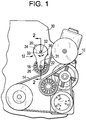
- Fig. 1 is a front view of a belt system, generally designed 10, shown in association with a belt tensioner 12.
- the belt system 10 includes an endless power transmitting element 14, such as a belt, chain or the like, which passes around a variety of pulleys, gears, guides.
- the power transmitting element 14 thereby drives a plurality of driven accessories, and/or is driven by one or more of the components.
- the power transmitting element 14 can, in one case, take the form of a timing belt/chain, a drive belt/chain, a transmission belt/chain or the like for use in an automotive vehicle.
- the tensioner 12 engages the power transmitting element 14 to apply the desired force to the power transmitting element 14 and to induce the desired tension.
- the tensioner 12 includes an arm 18 movably coupled to a spring case or base 20.
- the tensioner 12 further includes a belt engagement surface 22 positioned at one end of the arm 18, and a biasing mechanism or energy storing device 24 positioned between and operatively engaging the arm 18 and spring case 20.
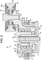
- the belt engagement surface 22 takes the form of a generally cylindrical roller 26 rotatably coupled to the arm 18 via a bearing 28, as shown in Fig. 2 , such that the roller 26 can rotate as the belt 14 rolls past the tensioner 12.
- the belt engagement surface 22 can take the form of a smooth, but non-rotatable, component with high-lubricity, or a toothed sprocket (for use with a chain), etc.
- the belt engagement surface 22 is aligned with, and/or rotatable about, an axis 31.
- the arm 18 is pivotally coupled to the spring case 20, and the spring case 20 is configured to be fixedly and non-rotatably coupled to an anchor body 30, such as an engine, engine block, engine cover, frame, etc.
- the tensioner 12/spring case 20 is coupled to the anchor body 30 by a threaded fastener 32, such as a bolt, extending through a central opening 34 of a pivot tube 37 of the tensioner 12 and into the anchor body 30.
- the bolt 32 thereby defines, or is aligned with, an axis 33 about which the arm 18 is pivotable.
- the axis 33 is thus, in the illustrated embodiment, radially offset from the axis 31 of the belt engagement surface 22.
- the tensioner 12 could also be configured in and/or mounted in various other configurations and manners, such as in a tab/ear mounting configuration.
- the biasing mechanism 24 can take the form of a spring, such as a helical coil spring in the illustrated embodiment.
- the biasing mechanism 24 urges the arm 18/roller 26 into contact with the belt 14 with the desired amount of force, and allows the arm 18 to pivot about the axis 33 (i.e. in the directions of the arrow 36 shown in Fig. 1 ) to accommodate varying forces applied to the arm 18/roller 26 by the belt 14.
- a bushing 40 is positioned between the arm 18 and the spring case 20, and a spring cap 42, or cover, is located at one axial end of the spring 24 to cover and protect the spring 24.
- the arm 18 includes a pulley portion 18a carrying the roller 26 and a body portion 18b positioned adjacent to the spring case 20.
- the body portion 18b of the arm 18 includes a generally flat, center annular portion 44, a radially outer flange 46, and a radially inner flange 48 positioned between the center portion 44 and the outer flange 46 in the radial direction.
- the arm 18 also includes a connecting portion 50 positioned between the outer 46 and inner 48 flanges.
- the spring 24 is positioned adjacent to and radially inside the radially inner flange 48, and above and adjacent to the center portion 44.
- the spring case 20 includes an inner cylindrical portion 52, an outer cylindrical portion 56 and a generally flat body portion 54 positioned between the inner cylindrical portion 52 and the outer cylindrical portion 56 in the radial direction.
- the outer cylindrical portion 56 includes an end flange 58 extending radially outwardly from an upper end thereof.
- the outer cylindrical portion 56 and the end flange 58 of the spring case 20 are positioned between the outer flange 46 and the inner flange 48 of the arm 18 in a radial direction thereof. In this manner various portions of the arm 18 and spring case 20 nest, or overlap, in the axial and/or radial directions.
- the spring cap 42 is positioned at the upper, central end of the tensioner 12.
- the spring cap 42 includes an inner tube portion 60 which is positioned between the pivot tube 37 and the spring 24 such that the spring 24 is positioned between the inner tube portion 60/spring cap 42 and the radially inner flange 48 of the arm 18 in the radial direction.
- One end of the spring 24 is fixedly coupled to the arm 18 (e.g. in one case to the radially inner flange 48, or connecting portion 50, or center portion 44 of the arm 18), and the other end of the spring 24 is fixedly coupled to the spring cap 42 (e.g. in one case to the inner tube portion 60 of the spring cap 42).
- the spring cap 42 is, in turn, fixedly coupled to the spring case 20 via the pivot tube 37. In this manner, when the arm 18 is pivoted (i.e. in the direction of arrows 36 of Fig. 1 ), the spring 24 is wound or unwound, depending upon the direction of pivoting, to provide the desired biasing force to the arm 18.
- the bushing 40 is positioned between the arm 18 and the spring case 20.
- the bushing 40 includes a cylindrical portion 62 at one end thereof, a flange portion 64 at the other end thereof, and a generally conical portion 66 positioned between the flange portion 64 and the cylindrical portion 62.
- the cylindrical portion, or pivot bushing 62 helps to provide proper radial alignment between the arm 18 and spring case 20, and is positioned between the outer cylindrical portion 56 of the spring case 20 and the radially inner flange 48 of the arm 18.
- the flange portion of the bushing, or spring bushing 64 helps to provide proper axial alignment between the arm 18 and the spring case 20, and is positioned between the end flange 58 of the spring case 20 and the connecting portion 50 of the arm 18.
- the conical portion of the bushing provides damping characteristics to the tensioner 12, and can provide radial and/or axial positioning between the arm 18 and spring case 20, and is positioned between the outer cylindrical portion 56 of the spring case 20 and the radially inner flange 48 of the arm 18.
- the bushing 40 can be made from a wide variety of materials, but is made of plastic or polymer materials in one case. Further details relating to tensioners, which can utilize the seals disclosed herein, can be found in U.S. Patent Nos. 7,497,796 , 7,887,445 , 8,075,433 , and 6,575,860 , the entire contents of which are incorporated herein.
- a seal system 70 is provided to reduce the penetration of contaminants to the bushing or other components.
- the illustrated seal system 70 includes a V-ring seal 72, or lip seal, having a body portion 74 and an integral, flexible flange 76.
- a gap 78 is positioned between the flange 76 and the body portion 74, and the flange 76 is relatively thin, and therefore deflectable, relative to the body portion 74.
- the seal 72 is positioned on the radially outer surface of the outer cylindrical portion 56, and below the end flange 58 of the spring case 20.
- the seal system 70 further includes a seal plate 80 that is coupled to the outer flange 46 of the arm 18, extending radially inwardly therefrom.
- the seal plate 80 can be secured to the outer flange 46/arm 18 by staking, but could also be secured by various means, such as welding, adhesives, brazing, etc.
- the seal plate 80 can be formed as a unitary one-piece body with the arm 18/outer flange 46.
- the upper surface 82 of the seal plate 80 defines a seal counterface which sealingly engages the flange 76 of the seal 72.
- the seal 72 and seal plate 80 are arranged such that the seal 72/flange 76 is placed into compression in the axial direction when the tensioner 12 is assembled/mounted to ensure proper sealing and allow for wear in the tensioner 12.
- the seal 72 may also be stretched/placed in tension in the radial direction by stretching the seal 72 to a greater diameter than the seal 72 assumes when it is not mounted to the tensioner 12.
- the seal 72 can be made of a wide variety of materials, such as rubber, synthetic rubber, a butyl material, a trial nitrile, etc.
- the seal 72 can take a variety of configurations besides the V-ring seal shown herein, such as O-rings, X-rings and U-rings.
- the seal 72 may be relatively compressible but have the ability to accommodate relatively high tolerances and wear. In particular, it may be desired for the seal 72 to be compressible to allow some travel/movement, but not provide much resistance to such travel/movement.
- the V-ring seal provides a relatively high amount of travel (to allow for wear and tolerance) without much compressive force, thereby reducing temporary damping and damping variation from seal contact.
- other shapes can be utilized.
- the axial position of the arm 18 relative to the spring case 20 can be shifted (typically, the arm 18 and spring case 20 on either side of the flange portion 64 move closer together in the axial direction).
- This shift in position causes the seal plate 80 to move axially away from the seal 72.
- the seal 72/flange 76 simply expands in the axial direction, increasing its gland size, following the seal plate 80 and maintaining a proper seal.
- the seal assembly 70 can accommodate a shift in axial position between the seal plate 80 and seal 72 in either axial direction. In this manner wearing of the bushing 40, and axial shifts in position between the arm 18 and spring case 20, are easily accommodated.
- the seal assembly 70 can also accommodate wear in the cylindrical portion 62 of the bushing 40. In particular, such wear may cause the seal 72 to move radially inwardly or outwardly relative to the seal plate 80. In this case, however, the flange 76/seal 72 simply slides radially inwardly across the seal plate 80/counterface 82 to accommodate such a shift in position.
- the seal assembly 70 may have or provide radial clearance for the seal 72 on either side of the seal plate 80 to allow the seal 72/flange 76 to slide radially across the seal plate 80, while maintaining the seal.
- such radial movement of the seal 72 across the seal plate 80 is designed to accommodate wear, and is not necessarily designed to accommodate off-center or eccentric movement of the arm 18 relative to the spring case 20.
- the conical portion 66 of the bushing 40 may cause the seal 72 to shift both axially and radially relative to the seal plate 80.
- the compressible/movable nature of the seal 72 enables the seal assembly 70 to accommodate such wear/movement.
- the bushing 40 or parts thereof may wear unevenly over time, which can cause the arm 18 to pitch, or form an angle, relative to the spring case 20.
- the flexible, dynamic nature of the seal assembly 70 therefore allows the seal assembly 70 to accommodate such pitching or offset of the arm 18.
- the seal assembly 70 thereby maintains a seal around the bushing 40 to prevent contaminants, such as dust, dirt, fluids and other environmental factors from reaching the bushing 40, helping to ensure proper operation of the tensioner 12 and extending the life of the tensioner.
- the illustrated seal assembly 70 is also positioned radially outside the spring 24, isolating the spring 24 from the outside environment. The seal assembly 70 thus helps to protect the spring 24, extend its useful life, and ensuring proper operation of the tensioner 12.
- the seal 72/seal assembly 70 is concentrically/coaxially mounted relative to the bolt 32/axis 33. This arrangement helps to ensure that, under normal operating conditions, the seal 72 does not move in the radial direction relative to the seal counterface 82 whenever the arm 18 is pivoted relative to the spring case 20. In particular, repeated radial movement of the seal 72 relative to the seal counterface 82 could create a sweeping action that could lead to the introduction of contaminants inside the seal assembly 70, which could cause wear in the bushing 40 or other components, and could also cause wear in the seal 72 itself.
- Fig. 2 illustrates the seal 72 in a particular arrangement in which the flange 76 of the seal 72 is positioned on the bottom side of the seal 72, engaging the seal plate 80.
- this configuration can be reversed such that the body 74 of the seal 72 is positioned adjacent to the seal plate 80, and the flange 76 of the seal 72 is positioned at the top, engaging the end flange 58 of the spring case 20.
- the seal assembly 70 can still accommodate axial and radial movement between the arm 18 and spring case 20 in all directions.
- the seal 72 can be turned on its side in either direction thereof, such that the flange 76 faces either the outer cylindrical portion 56 of the spring case 20 or the radially outer flange 46 of the arm 18, while still maintaining a proper seal and accommodating relative axial and radial movements between the arm 18 and spring case 20.
- the seal 72 can be rotated 90°, 180°, or 270° from its position shown in Fig. 2 .
- Fig. 3 illustrates an alternate embodiment having a seal assembly 70' similar to that of Fig. 2 and described above.
- the tensioner 12 of Fig. 3 is somewhat similar to that of Fig. 2 , but utilizes a pivot tube 37 formed as one piece with the spring case 20, and the spring 24 is an expansion spring which unwinds as the tensioner 12 moves from its free arm to its nominal position.
- the spring cap 42 has an inner tube portion 60 with a shorter axial length than that in the embodiment of Fig. 2
- the seal 72 is positioned above (instead of below) the end flange 58 of the spring case 20, and engages the underside of the connecting portion 50 of the arm 18.
- the underside of the connecting portion 50 acts as the seal counterface 82 that the seal 72 flexibly and sealingly engages, providing the same benefits as described above in the embodiment of the Fig. 2 .
- the seal 72 in this embodiment, is rotated 180° from the position of the seal 72 shown in the embodiment of Fig. 2 such that the flange 76 is positioned on the top side of the seal 72.
- the seal 72 in Fig. 3 (as well as the other embodiments described below and shown in Figs. 4 and 5 ) can also be arranged in the various other configurations and orientations, and take the form of the various seals and utilize the same materials described above in the context of Fig. 2 .
- the seal 72 in the embodiment of Fig. 3 , is positioned on top of the end flange 58, instead of the below the end flange 58 (as in the embodiment of Fig. 2 ), the seal 72 will be compressed (instead of expand) when the arm 18 and spring case 20 move closer together (e.g. when the flange portion 64 of the bushing 40 wears). In this case, however, the seal 72/flange 76 is simply compressed and retains the desired seal.
- the embodiment of Fig. 3 also utilizes a supplemental, or secondary seal 86.
- the secondary seal is a V-ring seal 86 having a body portion 88, flange 90 and gap 92.
- the secondary seal 86 is sealingly positioned between the spring cap 42 and the arm 18, in a groove 94 on the underside of the spring cap 42.
- the secondary seal 86 is positioned adjacent to the head of the fastener 32 (e.g., in one case, closer to the head of the fastener 32 than to the distal end).
- the secondary seal 86 of Fig. 3 can also be located in any of the four rotational positions described above for the primary seal.
- the secondary seal 86 can have the same dynamic seal characteristics as the primary seal 72 described above. For example, as the spring bushing 40, or flange portion 64 of the bushing 40, wears, the axial gap between the arm 18 and spring case 24 may be reduced, thereby causing the arm 18 to move away from the spring cap 42, and the secondary seal 86 expands (i.e. its gland area increases). Thus, it can be seen that the primary 72 and secondary 86 seals, in the embodiment of Fig. 3 , operate in tandem such that as one seal 72/86 expands, the other is compressed. However, it is also possible that the primary seal 72 can utilize the configuration/orientation shown in Fig. 2 , in which case the primary 72 and secondary 86 seals would expand/compress in the same manner.
- the secondary seal 86 blocks external contaminants from reaching the bushing 40 through any gap between the spring cap 42 and the arm 18.
- the primary seal 72 prevents contaminants from reaching a first (upper) exposed end of the bushing 40
- the secondary seal 86 prevents contaminants from reaching a second (lower) exposed end of the bushing 40.
- the secondary seal 86 of Fig. 3 can also be utilized in the tensioner of Fig. 2 , or in the other designs disclosed herein.
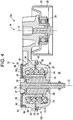
- Fig. 4 illustrates another tensioner 12 which is somewhat similar in operation and principle to those of Figs. 2 and 3 , but utilizes a lower-offset design. Moreover, rather than having portions of the arm 18 and spring case 20 nest or overlap significantly in the axial direction, the arm 18 and spring case 20 meet in a planar face-to-face contact area separated by a spring bushing or flange bushing 64. The inner flange 48 of the arm 18 is positioned radially inside the spring 24, adjacent to the pivot tube 37.
- the tensioner 12 of Fig. 4 further includes a pivot bushing 62 between the arm 18 and the pivot tube 37, and a damper bushing 66 positioned at an axial top surface thereof.
- a deflected arm plate, or cover 98 is positioned on top of the damper bushing 66 to maintain the damper bushing 66 in place.
- three separate bushing 62, 64, 66 are provided, each bushing 62, 64, 66 providing a separate function.
- the embodiment of Fig. 4 uses a seal system 70" which is similar in appearance and function to the seal system 70' disclosed in Fig. 3 .
- the seal 72 is positioned such that the body 74 is positioned adjacent to (and above) the end flange 58 of the spring case 20, and the flange 76 of the seal 72 engages the arm 18.
- the seal system 70" is positioned at roughly/generally the axial midpoint of the tensioner 12 and positioned adjacent to the spring bushing 64 to fluidly isolate the spring bushing 64 and prevent contaminants from contacting the spring bushing 64.
- the embodiment of Fig. 4 also utilizes a secondary seal 86', somewhat similar to the secondary seal 86 of Fig. 3 .
- the secondary seal 86' of Fig. 4 is positioned between the arm 18 and the deflected arm plate 98.
- the secondary seal 86' in Fig. 4 is shown rotated 180° from the position of secondary seal 86 of Fig. 3 .
- the secondary seal 86' of Fig. 4 can be located in either position.
- the secondary seal 86' fluidly isolates and protects the damper bushing 66 from contaminants.
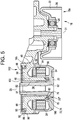
- Fig. 5 illustrates another tensioner 12 with a moderate offset and utilizing a flat spring 24, instead of a spring with a round cross section as in Figs. 2-4 .
- the pivot tube 37 is formed as one piece with the spring case 20.
- the tensioner of Fig. 5 12 includes a bushing component 102 including both a cylindrical portion 62, positioned between the arm 18 and the pivot tube 37/spring case 20, and a damper portion 66, positioned between the deflected arm plate 98 and the arm 18.
- the tensioner 12 also includes a flange portion bushing 64 positioned between the face-to-face contact area of the arm 18 and the spring case 20, somewhat similar to the bushing 64 in the embodiment of Fig. 4 .
- the seal 70" is positioned at a radially inner position between the arm 18 and spring case 20, radially inside a seal stop 100 that is integral with the spring case 20.
- the flat spring 24 includes an anchor hook which is positioned externally of the spring case 20, thereby making sealing of the spring case 20/tenioner 12 difficult. Accordingly, in this case, the seal 70" is positioned radially inwardly of the spring 24, adjacent to the bushing 62, and sealingly positioned between the arm 18 and spring case 20 to seal the bushing 62.
- the secondary seal 86' is positioned between the arm 18 and the deflected arm plate 98, similar to the secondary seal 86' in the embodiment of Fig. 4 .
- the secondary seal 86' is positioned in a generally closed cavity and therefore can be located in any of the four radial positions referenced above.
- the primary 72 and secondary 86' seals of Fig. 5 seal the cylindrical portion 62 and damper bushing portions 60 to ensure proper operation of the tensioner 12.
- the various seals disclosed herein help to prevent contaminants from reaching various internal components of the tensioner, including in various cases the bushings or parts thereof, the spring, or other parts. Reducing the introduction of contaminants thereby helps to provide longer life and proper operation to the tensioner, which in turn extends the life and ensure proper operation of the belt system 10.
Landscapes
- Engineering & Computer Science (AREA)
- General Engineering & Computer Science (AREA)
- Mechanical Engineering (AREA)
- Devices For Conveying Motion By Means Of Endless Flexible Members (AREA)
- Sealing Devices (AREA)
- Pivots And Pivotal Connections (AREA)
Description
- The present invention is directed to a belt tensioning device, and more particularly, to a belt tensioning device with one or more seals incorporated therein.
- Belt tensioners are utilized to ensure the associated belt, such as a belt in an automotive vehicle, is placed and maintained in the desired state of tension. Such belt tensioners can in some cases be exposed to environmental factors and outside contaminants, such as dust, dirt, fluids, etc. However, many existing belt tensioners do not provide sufficient protection from such environmental factors and outside contaminants.
- Examples of known tensioners are disclosed in documents
US 5354242 A ,DE102006057001 A1 ,DE102007059277 A1 ,DE102005031593 A1 orWO2011018297 A1 which can be considered the closest prior art document with respect to the present invention. - In view of the above, the need is felt to provide belt tensioners having sufficient protection from the aforementioned environmental factors and outside contaminants
- The aforementioned aims are reached by a tensioning system according to the appended set of claims.
-
-
Fig. 1 is a front view of a belt system utilizing a tensioner; -
Fig. 2 is a side cross section of the tensioner ofFig. 1 , taken along line 2-2; -
Fig. 3 is a side cross section of an alternate tensioner; -
Fig. 4 is a side cross section of another alternate tensioner; and -
Fig. 5 is a side cross section of yet another alternate tensioner. -
Fig. 1 is a front view of a belt system, generally designed 10, shown in association with abelt tensioner 12. Thebelt system 10 includes an endless power transmittingelement 14, such as a belt, chain or the like, which passes around a variety of pulleys, gears, guides. The power transmittingelement 14 thereby drives a plurality of driven accessories, and/or is driven by one or more of the components. The power transmittingelement 14 can, in one case, take the form of a timing belt/chain, a drive belt/chain, a transmission belt/chain or the like for use in an automotive vehicle. Thetensioner 12 engages thepower transmitting element 14 to apply the desired force to thepower transmitting element 14 and to induce the desired tension. - With reference to
Figs. 1 and2 , thetensioner 12 includes anarm 18 movably coupled to a spring case orbase 20. Thetensioner 12 further includes abelt engagement surface 22 positioned at one end of thearm 18, and a biasing mechanism orenergy storing device 24 positioned between and operatively engaging thearm 18 andspring case 20. In one embodiment, thebelt engagement surface 22 takes the form of a generallycylindrical roller 26 rotatably coupled to thearm 18 via abearing 28, as shown inFig. 2 , such that theroller 26 can rotate as thebelt 14 rolls past thetensioner 12. Alternately thebelt engagement surface 22 can take the form of a smooth, but non-rotatable, component with high-lubricity, or a toothed sprocket (for use with a chain), etc. Thebelt engagement surface 22 is aligned with, and/or rotatable about, anaxis 31. - The
arm 18 is pivotally coupled to thespring case 20, and thespring case 20 is configured to be fixedly and non-rotatably coupled to ananchor body 30, such as an engine, engine block, engine cover, frame, etc. In one embodiment thetensioner 12/spring case 20 is coupled to theanchor body 30 by a threadedfastener 32, such as a bolt, extending through acentral opening 34 of apivot tube 37 of thetensioner 12 and into theanchor body 30. Thebolt 32 thereby defines, or is aligned with, anaxis 33 about which thearm 18 is pivotable. Theaxis 33 is thus, in the illustrated embodiment, radially offset from theaxis 31 of thebelt engagement surface 22. Thetensioner 12 could also be configured in and/or mounted in various other configurations and manners, such as in a tab/ear mounting configuration. - The
biasing mechanism 24 can take the form of a spring, such as a helical coil spring in the illustrated embodiment. Thebiasing mechanism 24 urges thearm 18/roller 26 into contact with thebelt 14 with the desired amount of force, and allows thearm 18 to pivot about the axis 33 (i.e. in the directions of thearrow 36 shown inFig. 1 ) to accommodate varying forces applied to thearm 18/roller 26 by thebelt 14. Abushing 40 is positioned between thearm 18 and thespring case 20, and aspring cap 42, or cover, is located at one axial end of thespring 24 to cover and protect thespring 24. - In the embodiment of
Fig. 2 , thearm 18 includes apulley portion 18a carrying theroller 26 and abody portion 18b positioned adjacent to thespring case 20. Thebody portion 18b of thearm 18 includes a generally flat, centerannular portion 44, a radiallyouter flange 46, and a radiallyinner flange 48 positioned between thecenter portion 44 and theouter flange 46 in the radial direction. Thearm 18 also includes a connectingportion 50 positioned between the outer 46 and inner 48 flanges. Thespring 24 is positioned adjacent to and radially inside the radiallyinner flange 48, and above and adjacent to thecenter portion 44. - The
spring case 20 includes an innercylindrical portion 52, an outercylindrical portion 56 and a generallyflat body portion 54 positioned between the innercylindrical portion 52 and the outercylindrical portion 56 in the radial direction. The outercylindrical portion 56 includes anend flange 58 extending radially outwardly from an upper end thereof. The outercylindrical portion 56 and theend flange 58 of thespring case 20 are positioned between theouter flange 46 and theinner flange 48 of thearm 18 in a radial direction thereof. In this manner various portions of thearm 18 andspring case 20 nest, or overlap, in the axial and/or radial directions. - The
spring cap 42 is positioned at the upper, central end of thetensioner 12. Thespring cap 42 includes aninner tube portion 60 which is positioned between thepivot tube 37 and thespring 24 such that thespring 24 is positioned between theinner tube portion 60/spring cap 42 and the radiallyinner flange 48 of thearm 18 in the radial direction. - One end of the
spring 24 is fixedly coupled to the arm 18 (e.g. in one case to the radiallyinner flange 48, or connectingportion 50, orcenter portion 44 of the arm 18), and the other end of thespring 24 is fixedly coupled to the spring cap 42 (e.g. in one case to theinner tube portion 60 of the spring cap 42). Thespring cap 42 is, in turn, fixedly coupled to thespring case 20 via thepivot tube 37. In this manner, when thearm 18 is pivoted (i.e. in the direction ofarrows 36 ofFig. 1 ), thespring 24 is wound or unwound, depending upon the direction of pivoting, to provide the desired biasing force to thearm 18. - In the embodiment of
Fig. 2 , thebushing 40 is positioned between thearm 18 and thespring case 20. In the illustrated embodiment thebushing 40 includes acylindrical portion 62 at one end thereof, aflange portion 64 at the other end thereof, and a generallyconical portion 66 positioned between theflange portion 64 and thecylindrical portion 62. The cylindrical portion, or pivot bushing 62, helps to provide proper radial alignment between thearm 18 andspring case 20, and is positioned between the outercylindrical portion 56 of thespring case 20 and the radiallyinner flange 48 of thearm 18. The flange portion of the bushing, or spring bushing 64, helps to provide proper axial alignment between thearm 18 and thespring case 20, and is positioned between theend flange 58 of thespring case 20 and the connectingportion 50 of thearm 18. - Finally, the conical portion of the bushing, or the
damper bushing 66, provides damping characteristics to thetensioner 12, and can provide radial and/or axial positioning between thearm 18 andspring case 20, and is positioned between the outercylindrical portion 56 of thespring case 20 and the radiallyinner flange 48 of thearm 18. Thebushing 40 can be made from a wide variety of materials, but is made of plastic or polymer materials in one case. Further details relating to tensioners, which can utilize the seals disclosed herein, can be found inU.S. Patent Nos. 7,497,796 ,7,887,445 ,8,075,433 , and6,575,860 , the entire contents of which are incorporated herein. - In some cases environmental factors and outside contaminants, such as dust, dirt, fluids, etc. can penetrate the
tensioner 12 and cause thebushing 40, or other components, to wear. Wearing of the bushing 40 or other components can adversely effect the performance of thetensioner 12. Therefore, in the embodiment ofFig. 2 aseal system 70 is provided to reduce the penetration of contaminants to the bushing or other components. - The illustrated
seal system 70 includes a V-ring seal 72, or lip seal, having abody portion 74 and an integral,flexible flange 76. Agap 78 is positioned between theflange 76 and thebody portion 74, and theflange 76 is relatively thin, and therefore deflectable, relative to thebody portion 74. In the illustrated embodiment, theseal 72 is positioned on the radially outer surface of the outercylindrical portion 56, and below theend flange 58 of thespring case 20. - The
seal system 70 further includes aseal plate 80 that is coupled to theouter flange 46 of thearm 18, extending radially inwardly therefrom. Theseal plate 80 can be secured to theouter flange 46/arm 18 by staking, but could also be secured by various means, such as welding, adhesives, brazing, etc. Alternatively, theseal plate 80 can be formed as a unitary one-piece body with thearm 18/outer flange 46. - The
upper surface 82 of theseal plate 80 defines a seal counterface which sealingly engages theflange 76 of theseal 72. In particular, theseal 72 andseal plate 80 are arranged such that theseal 72/flange 76 is placed into compression in the axial direction when thetensioner 12 is assembled/mounted to ensure proper sealing and allow for wear in thetensioner 12. Theseal 72 may also be stretched/placed in tension in the radial direction by stretching theseal 72 to a greater diameter than theseal 72 assumes when it is not mounted to thetensioner 12. Theseal 72 can be made of a wide variety of materials, such as rubber, synthetic rubber, a butyl material, a trial nitrile, etc. Moreover, theseal 72 can take a variety of configurations besides the V-ring seal shown herein, such as O-rings, X-rings and U-rings. Theseal 72 may be relatively compressible but have the ability to accommodate relatively high tolerances and wear. In particular, it may be desired for theseal 72 to be compressible to allow some travel/movement, but not provide much resistance to such travel/movement. The V-ring seal provides a relatively high amount of travel (to allow for wear and tolerance) without much compressive force, thereby reducing temporary damping and damping variation from seal contact. However, other shapes can be utilized. - As the
flange portion 64 of thebushing 40 wears, the axial position of thearm 18 relative to thespring case 20 can be shifted (typically, thearm 18 andspring case 20 on either side of theflange portion 64 move closer together in the axial direction). This shift in position causes theseal plate 80 to move axially away from theseal 72. In this case theseal 72/flange 76 simply expands in the axial direction, increasing its gland size, following theseal plate 80 and maintaining a proper seal. On the other hand, if theseal plate 80 were to move toward the seal 72 (for example, due to uneven wear of thebushing 40 causing canting or skewing of thearm 18 relative to the spring plate 20), theseal 72/flange 76 will be compressed, decreasing its gland size, and again maintaining a proper seal. - Therefore, the
seal assembly 70 can accommodate a shift in axial position between theseal plate 80 andseal 72 in either axial direction. In this manner wearing of thebushing 40, and axial shifts in position between thearm 18 andspring case 20, are easily accommodated. - The
seal assembly 70 can also accommodate wear in thecylindrical portion 62 of thebushing 40. In particular, such wear may cause theseal 72 to move radially inwardly or outwardly relative to theseal plate 80. In this case, however, theflange 76/seal 72 simply slides radially inwardly across theseal plate 80/counterface 82 to accommodate such a shift in position. Theseal assembly 70 may have or provide radial clearance for theseal 72 on either side of theseal plate 80 to allow theseal 72/flange 76 to slide radially across theseal plate 80, while maintaining the seal. However, it should be noted that such radial movement of theseal 72 across theseal plate 80 is designed to accommodate wear, and is not necessarily designed to accommodate off-center or eccentric movement of thearm 18 relative to thespring case 20. - Wear of the
conical portion 66 of thebushing 40 may cause theseal 72 to shift both axially and radially relative to theseal plate 80. As described above, however, the compressible/movable nature of theseal 72 enables theseal assembly 70 to accommodate such wear/movement. As also noted above, thebushing 40 or parts thereof may wear unevenly over time, which can cause thearm 18 to pitch, or form an angle, relative to thespring case 20. The flexible, dynamic nature of theseal assembly 70 therefore allows theseal assembly 70 to accommodate such pitching or offset of thearm 18. - The
seal assembly 70 thereby maintains a seal around thebushing 40 to prevent contaminants, such as dust, dirt, fluids and other environmental factors from reaching thebushing 40, helping to ensure proper operation of thetensioner 12 and extending the life of the tensioner. The illustratedseal assembly 70 is also positioned radially outside thespring 24, isolating thespring 24 from the outside environment. Theseal assembly 70 thus helps to protect thespring 24, extend its useful life, and ensuring proper operation of thetensioner 12. - In the illustrated embodiment, the
seal 72/seal assembly 70 is concentrically/coaxially mounted relative to thebolt 32/axis 33. This arrangement helps to ensure that, under normal operating conditions, theseal 72 does not move in the radial direction relative to theseal counterface 82 whenever thearm 18 is pivoted relative to thespring case 20. In particular, repeated radial movement of theseal 72 relative to theseal counterface 82 could create a sweeping action that could lead to the introduction of contaminants inside theseal assembly 70, which could cause wear in thebushing 40 or other components, and could also cause wear in theseal 72 itself. -
Fig. 2 illustrates theseal 72 in a particular arrangement in which theflange 76 of theseal 72 is positioned on the bottom side of theseal 72, engaging theseal plate 80. However, this configuration can be reversed such that thebody 74 of theseal 72 is positioned adjacent to theseal plate 80, and theflange 76 of theseal 72 is positioned at the top, engaging theend flange 58 of thespring case 20. In this reversed configuration theseal assembly 70 can still accommodate axial and radial movement between thearm 18 andspring case 20 in all directions. Moreover, theseal 72 can be turned on its side in either direction thereof, such that theflange 76 faces either the outercylindrical portion 56 of thespring case 20 or the radiallyouter flange 46 of thearm 18, while still maintaining a proper seal and accommodating relative axial and radial movements between thearm 18 andspring case 20. Thus, theseal 72 can be rotated 90°, 180°, or 270° from its position shown inFig. 2 . -
Fig. 3 illustrates an alternate embodiment having a seal assembly 70' similar to that ofFig. 2 and described above. Thetensioner 12 ofFig. 3 is somewhat similar to that ofFig. 2 , but utilizes apivot tube 37 formed as one piece with thespring case 20, and thespring 24 is an expansion spring which unwinds as thetensioner 12 moves from its free arm to its nominal position. Moreover, thespring cap 42 has aninner tube portion 60 with a shorter axial length than that in the embodiment ofFig. 2 - In the embodiment of
Fig. 3 theseal 72 is positioned above (instead of below) theend flange 58 of thespring case 20, and engages the underside of the connectingportion 50 of thearm 18. In this manner, the underside of the connectingportion 50 acts as theseal counterface 82 that theseal 72 flexibly and sealingly engages, providing the same benefits as described above in the embodiment of theFig. 2 . Moreover, theseal 72, in this embodiment, is rotated 180° from the position of theseal 72 shown in the embodiment ofFig. 2 such that theflange 76 is positioned on the top side of theseal 72. Theseal 72 inFig. 3 (as well as the other embodiments described below and shown inFigs. 4 and5 ) can also be arranged in the various other configurations and orientations, and take the form of the various seals and utilize the same materials described above in the context ofFig. 2 . - Since the
seal 72, in the embodiment ofFig. 3 , is positioned on top of theend flange 58, instead of the below the end flange 58 (as in the embodiment ofFig. 2 ), theseal 72 will be compressed (instead of expand) when thearm 18 andspring case 20 move closer together (e.g. when theflange portion 64 of thebushing 40 wears). In this case, however, theseal 72/flange 76 is simply compressed and retains the desired seal. - The embodiment of
Fig. 3 also utilizes a supplemental, orsecondary seal 86. In this embodiment, the secondary seal is a V-ring seal 86 having abody portion 88,flange 90 andgap 92. Thesecondary seal 86 is sealingly positioned between thespring cap 42 and thearm 18, in agroove 94 on the underside of thespring cap 42. In the illustrated embodiment, thesecondary seal 86 is positioned adjacent to the head of the fastener 32 (e.g., in one case, closer to the head of thefastener 32 than to the distal end). Thesecondary seal 86 ofFig. 3 can also be located in any of the four rotational positions described above for the primary seal. - The
secondary seal 86 can have the same dynamic seal characteristics as theprimary seal 72 described above. For example, as thespring bushing 40, orflange portion 64 of thebushing 40, wears, the axial gap between thearm 18 andspring case 24 may be reduced, thereby causing thearm 18 to move away from thespring cap 42, and thesecondary seal 86 expands (i.e. its gland area increases). Thus, it can be seen that the primary 72 and secondary 86 seals, in the embodiment ofFig. 3 , operate in tandem such that as oneseal 72/86 expands, the other is compressed. However, it is also possible that theprimary seal 72 can utilize the configuration/orientation shown inFig. 2 , in which case the primary 72 and secondary 86 seals would expand/compress in the same manner. - The
secondary seal 86 blocks external contaminants from reaching thebushing 40 through any gap between thespring cap 42 and thearm 18. Thus theprimary seal 72 prevents contaminants from reaching a first (upper) exposed end of thebushing 40, and thesecondary seal 86 prevents contaminants from reaching a second (lower) exposed end of thebushing 40. Thesecondary seal 86 ofFig. 3 can also be utilized in the tensioner ofFig. 2 , or in the other designs disclosed herein. -
Fig. 4 illustrates anothertensioner 12 which is somewhat similar in operation and principle to those ofFigs. 2 and3 , but utilizes a lower-offset design. Moreover, rather than having portions of thearm 18 andspring case 20 nest or overlap significantly in the axial direction, thearm 18 andspring case 20 meet in a planar face-to-face contact area separated by a spring bushing orflange bushing 64. Theinner flange 48 of thearm 18 is positioned radially inside thespring 24, adjacent to thepivot tube 37. Thetensioner 12 ofFig. 4 further includes apivot bushing 62 between thearm 18 and thepivot tube 37, and a damper bushing 66 positioned at an axial top surface thereof. A deflected arm plate, or cover 98, is positioned on top of the damper bushing 66 to maintain the damper bushing 66 in place. In this embodiment, then, rather than having asingle bushing 40 with three separate portions to provide three separate functions, threeseparate bushing bushing - The embodiment of
Fig. 4 uses aseal system 70" which is similar in appearance and function to the seal system 70' disclosed inFig. 3 . In particular, theseal 72 is positioned such that thebody 74 is positioned adjacent to (and above) theend flange 58 of thespring case 20, and theflange 76 of theseal 72 engages thearm 18. However, in the embodiment ofFig. 4 theseal system 70" is positioned at roughly/generally the axial midpoint of thetensioner 12 and positioned adjacent to thespring bushing 64 to fluidly isolate thespring bushing 64 and prevent contaminants from contacting thespring bushing 64. - The embodiment of
Fig. 4 also utilizes a secondary seal 86', somewhat similar to thesecondary seal 86 ofFig. 3 . However, the secondary seal 86' ofFig. 4 is positioned between thearm 18 and the deflectedarm plate 98. Moreover, the secondary seal 86' inFig. 4 is shown rotated 180° from the position ofsecondary seal 86 ofFig. 3 . However, the secondary seal 86' ofFig. 4 can be located in either position. The secondary seal 86' fluidly isolates and protects the damper bushing 66 from contaminants. - In the embodiment of
Fig. 4 , when thespring bushing 64 wears, theprimary seal 72 will be further compressed (i.e. its gland area will decrease). When the damper bushing 66 wears, the secondary seal 86' will also be further compressed (i.e. its gland area will decrease). -
Fig. 5 illustrates anothertensioner 12 with a moderate offset and utilizing aflat spring 24, instead of a spring with a round cross section as inFigs. 2-4 . In this embodiment thepivot tube 37 is formed as one piece with thespring case 20. The tensioner ofFig. 5 12 includes abushing component 102 including both acylindrical portion 62, positioned between thearm 18 and thepivot tube 37/spring case 20, and adamper portion 66, positioned between the deflectedarm plate 98 and thearm 18. Thetensioner 12 also includes aflange portion bushing 64 positioned between the face-to-face contact area of thearm 18 and thespring case 20, somewhat similar to thebushing 64 in the embodiment ofFig. 4 . - In this embodiment, the
seal 70" is positioned at a radially inner position between thearm 18 andspring case 20, radially inside aseal stop 100 that is integral with thespring case 20. In this particular embodiment, theflat spring 24 includes an anchor hook which is positioned externally of thespring case 20, thereby making sealing of thespring case 20/tenioner 12 difficult. Accordingly, in this case, theseal 70" is positioned radially inwardly of thespring 24, adjacent to thebushing 62, and sealingly positioned between thearm 18 andspring case 20 to seal thebushing 62. - The secondary seal 86' is positioned between the
arm 18 and the deflectedarm plate 98, similar to the secondary seal 86' in the embodiment ofFig. 4 . However, in the embodiment ofFig. 5 , the secondary seal 86' is positioned in a generally closed cavity and therefore can be located in any of the four radial positions referenced above. Thus, the primary 72 and secondary 86' seals ofFig. 5 seal thecylindrical portion 62 anddamper bushing portions 60 to ensure proper operation of thetensioner 12. - As can be seen, the various seals disclosed herein help to prevent contaminants from reaching various internal components of the tensioner, including in various cases the bushings or parts thereof, the spring, or other parts. Reducing the introduction of contaminants thereby helps to provide longer life and proper operation to the tensioner, which in turn extends the life and ensure proper operation of the
belt system 10. - Having described the invention in detail and by reference to certain embodiments, it will be apparent that modifications and variations thereof are possible without departing from the scope of the invention.
Claims (13)
- A tensioning system (12) comprising:a base (20);an arm (18) pivotally coupled to said base (20), said arm (18) having an engagement surface (22) and being configured to pivot relative to said base (20) about a pivot axis (33);a biasing mechanism (24) operatively coupled to said arm (18) to bias said arm (18) relative to said base (20);a bushing (40) having a cyclindrical portion (62) at one end of the bushing and a flange portion (64) at the other end of the bushing, or separate bushings comprising a cylindrical bushing (62) and a spring bushing (64) positioned between said arm (18) and said base (20);a cover (42) fixedly coupled to said base (20) at an axial end thereof;wherein the cylindrical portion (62) or the cylindrical bushing (62) is positioned radially between an inner flange of the arm (18) and said base (20), thereby providing radial alignment between said arm and said base;wherein the flange portion (64) or the flange bushing (64) is positioned axially between an end flange (58) of the base (20) and a connecting portion (50) of the arm (18), thereby providing axial alignment between the arm and the base;wherein sufficient wear in said bushing (40) is configured to allow relative axial movement between said base (20) and said arm (18) or relative radial movement between said base (20) and said arm (18);a seal assembly (70') sealingly positioned between said arm (18) and said base (20), wherein said seal assembly (70') is coaxial with said pivot axis (33) and characterised in that said cover (42) is a spring cap or a deflected arm plate and in that said seal assembly (70') includes a primary seal (72) having a seal body (74) and a deflectable flange (76) coupled to said seal body, and wherein said flange (76) is in axial compression so that it is configured to accommodate relative axial movement between said base (20) and said arm (18) and relative radial movement between said base (20) and said arm (18) while still maintaining a seal therebetween; anda supplemental seal (86) sealingly positioned between said arm (18) and said cover (42);wherein said primary seal (72) is positioned and configured to block external contaminants from reaching a first exposed end of said bushing (40) and the supplemental seal (86) is positioned and configured to block external contaminants from reaching a second, opposite exposed end of said bushing (40);wherein said relative axial movement causes one of said primary seal (72) or said supplemental seal (86) to compress and the other one of said primary seal (72) and supplemental seal (86) to expand.
- The system of claim 1 wherein said seal assembly (70') is positioned radially outside said biasing mechanism (24) and configured to block external contaminants from reaching said biasing mechanism (24).
- The system of any preceding claim wherein said engagement surface (22) is rotatable about an axis that is radially offset from said pivot axis (33).
- The system of any preceding claim wherein said primary seal (72) has clearance on either radial side thereof to enable said primary seal (72) to move in either radial direction to accommodate said relative radial movement between said arm (18) and said base (20).
- The system of any preceding claim wherein said arm (18) includes an outer flange (46) positioned radially outside said base (20), and wherein said primary seal (72) is positioned radially between said outer flange (46) and said base (20).
- The system of any preceding claim wherein said arm (18) includes a portion (48) positioned radially inside at least part of said base (20) and said biasing mechanism (24) is positioned radially inside said portion (48) of the arm (18), and wherein said seal assembly (70') is positioned radially between said portion (48) and said base (20).
- The system of claim 1 wherein said seal assembly (70') includes a lip seal, or an O-ring, or a X-ring, or a U-ring extending circumferentially about said pivot axis.
- The system of claim 1 wherein the delfectable flange (76) engages the arm and the seal is positioned adjacent to the flange portion (64) or the flange bushing (64).
- The system of claim 1 comprising a damper bushing (66) or a damper portion (66) between a deflected arm plate (98) and the arm (18), wherein the supplemental seal (86) has a deflectable flange (90) and is also positioned between the deflected arm plate (98) and the arm (18) at a position that fluidly isolates and protects the damper bushing (66) or the damper portion (66) from contaminants.
- The system of claim 1 wherein the primary seal (70''') is positioned radially inward of the spring (24), adjacent to the cylindrical portion (62) or the cylindrical bushing (62) and sealingly positioned between the arm (18) and the base (20).
- The system of claim 1 wherein the arm (18) has a connecting portion (50) between an outer flange (46) and an inner flange (48), wherein the cyclindrical portion (62) or cylindrical bushing (62) is positioned between an outer cylindrical portion (56) of the base (20) and the inner flange (48) and the flange portion (64) or flange bushing (64) is positioned between an end flange (58) of the base (20) and the connecting portion (50) of the arm; wherein the primary seal (72) is positioned on the radially outer surface of the outer cylindrical portion (56) and below the end flange (58) of the base (20).
- The system of claim 1 wherein the arm (18) has a connecting portion (50) between an outer flange (46) and an inner flange (48), wherein the cyclindrical portion (62) or cylindrical bushing (62) is positioned between an outer cylindrical portion (56) of the base (20) and the inner flange (48) and the flange portion (64) or flange bushing (64) is positioned between an end flange (58) of the base (20) and the connecting portion (50) of the arm; wherein the primary seal (70''') is seated between the inner flange (48) of the arm (18) and a seal stop (100) of the base (20).
- The system of claim 1 wherein said supplemental seal (86) includes a lip seal, or an O-ring, or a X-ring, or a U-ring extending circumferentially about said pivot axis.
Priority Applications (2)
| Application Number | Priority Date | Filing Date | Title |
|---|---|---|---|
| EP24209431.6A EP4495457A3 (en) | 2012-03-28 | 2013-03-22 | Sealed belt tensioning device |
| EP21187222.1A EP3919779B1 (en) | 2012-03-28 | 2013-03-22 | Sealed belt tensioning device |
Applications Claiming Priority (2)
| Application Number | Priority Date | Filing Date | Title |
|---|---|---|---|
| US13/432,548 US9777806B2 (en) | 2012-03-28 | 2012-03-28 | Sealed belt tensioning device |
| PCT/US2013/033395 WO2013148477A1 (en) | 2012-03-28 | 2013-03-22 | Sealed belt tensioning device |
Related Child Applications (2)
| Application Number | Title | Priority Date | Filing Date |
|---|---|---|---|
| EP24209431.6A Division EP4495457A3 (en) | 2012-03-28 | 2013-03-22 | Sealed belt tensioning device |
| EP21187222.1A Division EP3919779B1 (en) | 2012-03-28 | 2013-03-22 | Sealed belt tensioning device |
Publications (3)
| Publication Number | Publication Date |
|---|---|
| EP2831467A1 EP2831467A1 (en) | 2015-02-04 |
| EP2831467A4 EP2831467A4 (en) | 2016-04-06 |
| EP2831467B1 true EP2831467B1 (en) | 2021-08-04 |
Family
ID=49235793
Family Applications (3)
| Application Number | Title | Priority Date | Filing Date |
|---|---|---|---|
| EP13770364.1A Active EP2831467B1 (en) | 2012-03-28 | 2013-03-22 | Sealed belt tensioning device |
| EP21187222.1A Active EP3919779B1 (en) | 2012-03-28 | 2013-03-22 | Sealed belt tensioning device |
| EP24209431.6A Pending EP4495457A3 (en) | 2012-03-28 | 2013-03-22 | Sealed belt tensioning device |
Family Applications After (2)
| Application Number | Title | Priority Date | Filing Date |
|---|---|---|---|
| EP21187222.1A Active EP3919779B1 (en) | 2012-03-28 | 2013-03-22 | Sealed belt tensioning device |
| EP24209431.6A Pending EP4495457A3 (en) | 2012-03-28 | 2013-03-22 | Sealed belt tensioning device |
Country Status (12)
| Country | Link |
|---|---|
| US (2) | US9777806B2 (en) |
| EP (3) | EP2831467B1 (en) |
| JP (1) | JP6185556B2 (en) |
| KR (1) | KR102166564B1 (en) |
| CN (2) | CN106907439B (en) |
| AR (1) | AR090383A1 (en) |
| AU (1) | AU2013240069A1 (en) |
| BR (1) | BR112014023428B1 (en) |
| CA (1) | CA2868280A1 (en) |
| IN (1) | IN2014MN02057A (en) |
| MX (1) | MX2014011172A (en) |
| WO (1) | WO2013148477A1 (en) |
Families Citing this family (23)
| Publication number | Priority date | Publication date | Assignee | Title |
|---|---|---|---|---|
| US9777806B2 (en) * | 2012-03-28 | 2017-10-03 | Dayco Ip Holdings, Llc | Sealed belt tensioning device |
| CN104797856B (en) | 2012-10-22 | 2018-04-17 | 利滕斯汽车合伙公司 | The stretcher of improvement of damping |
| US9249866B2 (en) * | 2013-03-15 | 2016-02-02 | Dayco Ip Holdings, Llc | Belt tensioner for a power transmission belt system |
| DE112014004168B4 (en) | 2013-09-11 | 2025-09-11 | Litens Automotive Partnership | Clamping device with increased damping and an arm-on-base shell configuration |
| DE102014206716A1 (en) * | 2014-04-08 | 2015-10-08 | Muhr Und Bender Kg | Belt tensioner |
| US9458920B2 (en) * | 2014-05-02 | 2016-10-04 | Dayco Ip Holdings, Llc | Reusable dust cap for a pulley assembly |
| EP2955414A1 (en) * | 2014-06-13 | 2015-12-16 | Aktiebolaget SKF | Tensioning device and method for assembling such a tensioning device |
| US20160186839A1 (en) * | 2014-12-26 | 2016-06-30 | The Gates Corporation | Tensioner with axial seal |
| DE102015111809A1 (en) * | 2015-07-21 | 2017-01-26 | Muhr Und Bender Kg | jig |
| US10066708B2 (en) * | 2016-08-04 | 2018-09-04 | Ford Global Technologies, Llc | External spring to increase tension on belt tensioner for internal combustion engine |
| US9890837B1 (en) * | 2016-09-15 | 2018-02-13 | Gates Corporation | Tensioner |
| JP2018096494A (en) * | 2016-12-15 | 2018-06-21 | Ntn株式会社 | Support structure of tensioner device |
| JP6867853B2 (en) * | 2017-04-13 | 2021-05-12 | バンドー化学株式会社 | Auto tensioner |
| US10995829B2 (en) * | 2017-06-16 | 2021-05-04 | Gates Corporation | Tensioner |
| SE542372C2 (en) | 2018-04-04 | 2020-04-21 | Husqvarna Ab | A floor surfacing machine with a tool holder disc comprising a biasing member |
| JP6761911B1 (en) * | 2018-12-14 | 2020-09-30 | バンドー化学株式会社 | Auto tensioner |
| JP7382150B2 (en) * | 2019-03-25 | 2023-11-16 | エドワーズ株式会社 | Vacuum pumps and seal members used in vacuum pumps |
| US11359702B2 (en) * | 2019-07-25 | 2022-06-14 | Shihwen Chan | Multi-configuration belt tensioner |
| US20220099165A1 (en) * | 2020-09-28 | 2022-03-31 | Caterpillar Inc. | Engine accessory drive system and one-piece bracket for same |
| DE102021103684A1 (en) | 2021-02-17 | 2022-08-18 | Schaeffler Technologies AG & Co. KG | belt tensioner |
| KR20230148170A (en) | 2021-02-26 | 2023-10-24 | 데이코 아이피 홀딩스 엘엘시 | High-clearance belt tensioner using countervailing torsion spring force |
| US12333542B2 (en) * | 2021-06-07 | 2025-06-17 | Mastercard Technologies Canada ULC | Systems, methods, and non-transitory computer- readable media for authentication and authorization of payment request |
| US12404916B2 (en) * | 2023-01-20 | 2025-09-02 | Muviq S.r.l. | Belt tensioner with integrated idler pulley for an endless drive belt of an engine |
Citations (3)
| Publication number | Priority date | Publication date | Assignee | Title |
|---|---|---|---|---|
| JPH0517252U (en) * | 1991-01-31 | 1993-03-05 | エヌテイエヌ株式会社 | Auto tensioner |
| US5259628A (en) * | 1992-07-23 | 1993-11-09 | Reliance Electric Industrial Company | Seal assembly |
| DE102005031558A1 (en) * | 2005-07-06 | 2007-01-11 | Schaeffler Kg | Tightening system for belt drive, comprises separate sealing elements for circular gaps |
Family Cites Families (60)
| Publication number | Priority date | Publication date | Assignee | Title |
|---|---|---|---|---|
| US3759146A (en) | 1972-04-07 | 1973-09-18 | Timesavers Inc | Belt tensioner for wide belt sanding machines |
| US4728317A (en) | 1981-08-27 | 1988-03-01 | Dayco Products, Inc. | Belt tensioner, part therefor and methods of making the same |
| US4832666A (en) | 1984-08-23 | 1989-05-23 | Dayco Products, Inc. | Belt tensioner and method of making the same |
| US4723934A (en) | 1986-10-29 | 1988-02-09 | Dyneer Corporation | Belt tensioner |
| JPH01141952U (en) | 1988-03-24 | 1989-09-28 | ||
| CA2000433C (en) | 1988-10-13 | 1994-09-20 | Hideo Hirai | Compact automatic belt tensioner |
| JP2655193B2 (en) | 1988-12-30 | 1997-09-17 | 日本発条株式会社 | Tensioner |
| US4938735A (en) | 1989-03-14 | 1990-07-03 | Dayco Products, Inc. | Belt tensioning system, tensioner and parts therefor and methods of making the same |
| JPH04300444A (en) | 1991-03-28 | 1992-10-23 | Fuji Kiko Co Ltd | Automatic tensioner |
| US5234384A (en) | 1990-09-29 | 1993-08-10 | Fujikiko Kabushiki Kaisha | Automatic tensioner |
| JP2586760B2 (en) | 1991-07-01 | 1997-03-05 | 株式会社イナックス | Foamed building material and method for producing the same |
| JP2577329Y2 (en) | 1992-04-23 | 1998-07-23 | 日本精工株式会社 | Auto tensioner |
| US5354242A (en) | 1992-10-08 | 1994-10-11 | St John Richard C | Automatic belt tensioner with an enclosed flat wire power spring and improved zeroing and damping means |
| DE4343429C2 (en) * | 1993-12-18 | 1999-08-12 | Schaeffler Waelzlager Ohg | Tensioning device for a belt or chain drive |
| DE4414193A1 (en) | 1994-04-22 | 1995-10-26 | Takata Europ Gmbh | Belt tensioners |
| US5462494A (en) | 1994-10-20 | 1995-10-31 | Dayco Products, Inc. | Belt tensioner and method of making the same |
| US5803849A (en) | 1995-06-14 | 1998-09-08 | Unitta Company | Belt tensioner |
| DE29515703U1 (en) | 1995-10-02 | 1996-02-08 | Föhl, Artur, 73614 Schorndorf | Rotary drive device for a belt tensioner |
| US5632697A (en) | 1995-12-18 | 1997-05-27 | The Gates Corporation | Damping mechanism for a tensioner |
| US5718649A (en) | 1996-02-16 | 1998-02-17 | Dayco Products, Inc. | Tensioner for a power transmission belt and method of making same |
| US5964674A (en) * | 1997-03-21 | 1999-10-12 | The Gates Corporation | Belt tensioner with bottom wall of base juxtaposed pivot arm |
| JP2951321B1 (en) | 1998-06-26 | 1999-09-20 | ユニッタ株式会社 | Auto tensioner |
| JP3253943B2 (en) * | 1999-12-22 | 2002-02-04 | ユニッタ株式会社 | Auto tensioner |
| JP4300444B2 (en) | 2000-09-21 | 2009-07-22 | 富士電機ホールディングス株式会社 | Toxic gas treatment equipment |
| US6575860B2 (en) | 2001-02-28 | 2003-06-10 | Dayco Products, Llc | Belt tensioner for a power transmission belt system |
| US6857979B2 (en) | 2001-10-26 | 2005-02-22 | Litens Automotive Partnership | Combination belt tensioner and idler |
| US7229374B2 (en) * | 2001-12-20 | 2007-06-12 | Dayco Products, Llc | Dual friction surface asymmetric damped tensioner |
| US6884194B2 (en) | 2002-02-07 | 2005-04-26 | Dayco Products, Llc | Hydraulic asymmetric damped belt tensioner |
| US7186196B2 (en) * | 2002-07-18 | 2007-03-06 | Dayco Products, Llc | Belt tensioner with integral damping |
| DE20220807U1 (en) | 2002-09-10 | 2004-04-01 | Litens Automotive Gmbh | tensioner |
| US6855079B2 (en) | 2002-09-30 | 2005-02-15 | Fenner, Inc. | Bi-directional belt tensioner |
| US7883436B2 (en) | 2004-09-15 | 2011-02-08 | Fenner U.S., Inc. | Bi-directional tensioner |
| US7837582B2 (en) | 2002-09-30 | 2010-11-23 | Fenner, Inc. | Bi-directional belt tensioner |
| US20110207568A1 (en) | 2002-09-30 | 2011-08-25 | Gary Smith | Bi-Directional Belt Tensioner |
| JP2004150602A (en) | 2002-10-31 | 2004-05-27 | Showa Corp | Belt tensioner |
| ITTO20021133A1 (en) | 2002-12-30 | 2004-06-30 | Dayco Europe Srl | TWO-ARM TENSIONER FOR A BELT DRIVE. |
| DE102005002253A1 (en) * | 2004-02-20 | 2005-09-01 | Ina-Schaeffler Kg | Pulley belt dampening mechanism for tensioning arm is located between the flange and bush |
| JP4364750B2 (en) | 2004-08-20 | 2009-11-18 | ゲイツ・ユニッタ・アジア株式会社 | Tensioner and labyrinth seal |
| US7497794B2 (en) * | 2004-11-05 | 2009-03-03 | Dayco Products, Llc | Belt tensioner and method for assembly |
| US7448974B2 (en) * | 2004-11-05 | 2008-11-11 | Dayco Products, Llc | Belt tensioner and method for making a belt-tensioner arm and a spring case |
| US7887445B2 (en) * | 2005-01-20 | 2011-02-15 | Dayco Products, Llc | Belt tensioner |
| US8075433B2 (en) | 2005-06-28 | 2011-12-13 | Dayco Products, Llc | Belt tensioner with damping member |
| DE102005031593A1 (en) | 2005-07-06 | 2007-01-11 | Schaeffler Kg | Seal for the bearing eye of a clamping system |
| US7497796B2 (en) | 2006-04-12 | 2009-03-03 | General Motors Corporation | Electro-mechanical transmission |
| US7678002B2 (en) | 2006-08-31 | 2010-03-16 | Dayco Products, Llc | One-way clutched damper for automatic belt tensioner |
| US20080119310A1 (en) | 2006-11-16 | 2008-05-22 | Holcombe C Scott | Rotary tensioner |
| DE102006057001A1 (en) | 2006-12-02 | 2008-06-05 | Schaeffler Kg | Clamping device for traction mechanism drive i.e. belt drive, has body formed with cone structure concentric to axis, where structure forms friction surface and spring device coupled to body and subjected to forces aligned radial to axis |
| FR2920851B1 (en) | 2007-09-12 | 2010-02-19 | Skf Ab | BELT TENSIONER BELT DEVICE |
| DE102007059277A1 (en) | 2007-12-08 | 2009-06-10 | Schaeffler Kg | Clamping and damping device for belt of tensioning unit drive in automobile engineering, has sealing rings with V- or Y-shaped cross-section and formed for balancing irregular clearance of annular gap between plate and/or inner cone and arm |
| US8529387B2 (en) * | 2008-04-30 | 2013-09-10 | Dayco Ip Holdings, Llc | Pulley with asymmetric torque-sensitive clutching |
| US20090286636A1 (en) | 2008-05-13 | 2009-11-19 | Alexander Serkh | Sealed tensioner |
| US8591359B2 (en) | 2008-05-22 | 2013-11-26 | Fenner U.S., Inc. | Tensioner assembly with sealed pulley |
| US8403785B2 (en) * | 2008-11-05 | 2013-03-26 | Dayco Ip Holdings, Llc | Clutched damper for a belt tensioner |
| US20100261564A1 (en) | 2009-04-13 | 2010-10-14 | Hughes Thomas E | Rotary tensioner |
| US8267821B2 (en) | 2009-07-15 | 2012-09-18 | Schaeffler Technologies AG & Co. KG | Mechanical tensioner with damping mechanism |
| US8905879B2 (en) | 2009-08-11 | 2014-12-09 | Dayco Ip Holdings, Llc | Deflected bearing shield as a bearing seal for a pulley assembly and method of assembly |
| DE102009037498A1 (en) | 2009-08-13 | 2011-02-17 | Schaeffler Technologies Gmbh & Co. Kg | Seal with self-reinforcing sealing lip for a clamping system |
| US8545352B2 (en) * | 2010-09-02 | 2013-10-01 | Dayco Ip Holdings, Llc | Tensioner with expanding spring for radial frictional asymmetric damping |
| US20130217525A1 (en) * | 2012-02-17 | 2013-08-22 | Dayco Products, Llc | Belt tensioning device with locating pin |
| US9777806B2 (en) * | 2012-03-28 | 2017-10-03 | Dayco Ip Holdings, Llc | Sealed belt tensioning device |
-
2012
- 2012-03-28 US US13/432,548 patent/US9777806B2/en active Active
-
2013
- 2013-03-19 AR ARP130100893A patent/AR090383A1/en unknown
- 2013-03-22 CN CN201710278306.7A patent/CN106907439B/en active Active
- 2013-03-22 EP EP13770364.1A patent/EP2831467B1/en active Active
- 2013-03-22 JP JP2015503404A patent/JP6185556B2/en active Active
- 2013-03-22 KR KR1020147027146A patent/KR102166564B1/en active Active
- 2013-03-22 MX MX2014011172A patent/MX2014011172A/en unknown
- 2013-03-22 EP EP21187222.1A patent/EP3919779B1/en active Active
- 2013-03-22 CA CA2868280A patent/CA2868280A1/en not_active Abandoned
- 2013-03-22 EP EP24209431.6A patent/EP4495457A3/en active Pending
- 2013-03-22 CN CN201380017081.XA patent/CN104220779B/en active Active
- 2013-03-22 AU AU2013240069A patent/AU2013240069A1/en not_active Abandoned
- 2013-03-22 IN IN2057MUN2014 patent/IN2014MN02057A/en unknown
- 2013-03-22 WO PCT/US2013/033395 patent/WO2013148477A1/en not_active Ceased
- 2013-03-22 BR BR112014023428-0A patent/BR112014023428B1/en active IP Right Grant
-
2017
- 2017-09-14 US US15/704,191 patent/US10458525B2/en active Active
Patent Citations (3)
| Publication number | Priority date | Publication date | Assignee | Title |
|---|---|---|---|---|
| JPH0517252U (en) * | 1991-01-31 | 1993-03-05 | エヌテイエヌ株式会社 | Auto tensioner |
| US5259628A (en) * | 1992-07-23 | 1993-11-09 | Reliance Electric Industrial Company | Seal assembly |
| DE102005031558A1 (en) * | 2005-07-06 | 2007-01-11 | Schaeffler Kg | Tightening system for belt drive, comprises separate sealing elements for circular gaps |
Also Published As
| Publication number | Publication date |
|---|---|
| KR102166564B1 (en) | 2020-10-16 |
| WO2013148477A1 (en) | 2013-10-03 |
| KR20140140563A (en) | 2014-12-09 |
| EP4495457A2 (en) | 2025-01-22 |
| CA2868280A1 (en) | 2013-10-03 |
| MX2014011172A (en) | 2014-11-14 |
| BR112014023428A2 (en) | 2017-06-20 |
| BR112014023428B1 (en) | 2022-05-17 |
| US20130260933A1 (en) | 2013-10-03 |
| US10458525B2 (en) | 2019-10-29 |
| JP6185556B2 (en) | 2017-08-23 |
| AR090383A1 (en) | 2014-11-05 |
| CN104220779A (en) | 2014-12-17 |
| US20180003271A1 (en) | 2018-01-04 |
| EP2831467A4 (en) | 2016-04-06 |
| JP2015518117A (en) | 2015-06-25 |
| EP2831467A1 (en) | 2015-02-04 |
| EP4495457A3 (en) | 2025-03-05 |
| CN104220779B (en) | 2017-05-03 |
| CN106907439B (en) | 2020-03-13 |
| IN2014MN02057A (en) | 2015-08-21 |
| US9777806B2 (en) | 2017-10-03 |
| EP3919779B1 (en) | 2024-10-30 |
| AU2013240069A1 (en) | 2014-10-02 |
| CN106907439A (en) | 2017-06-30 |
| EP3919779A1 (en) | 2021-12-08 |
Similar Documents
| Publication | Publication Date | Title |
|---|---|---|
| US10458525B2 (en) | Sealed belt tensioning device | |
| JP4435810B2 (en) | Pulley structure and accessory drive system using the same | |
| KR101623244B1 (en) | Tensioner with expanding spring for radial frictional asymmetric damping | |
| US9982761B2 (en) | Tensioner with improved damping | |
| US20090075768A1 (en) | Tensioner | |
| CA2837489A1 (en) | Tensioner | |
| WO2007025374A2 (en) | Low profile tensioner with arcuate spring | |
| US8460140B2 (en) | Belt tensioner utilizing asymmetric motion control | |
| US5073149A (en) | Diaphragm seal type tensioner | |
| WO2009143013A2 (en) | Tensioner assembly with sealed pulley | |
| US20030153419A1 (en) | Tensioning idler | |
| MX2011010578A (en) | Rotary tensioner. | |
| JP4846648B2 (en) | Chain tensioner | |
| CN103375553B (en) | Stretcher core body and there is stretcher and the commutator of this core body | |
| EP3137780A1 (en) | Reusable dust cap for a pulley assembly | |
| JPH10141453A (en) | Hydraulic auto tensioner | |
| JP7112941B2 (en) | auto tensioner | |
| HK1170790A (en) | Rotary tensioner | |
| JPH0522909U (en) | Transmission endless tension device | |
| CN103375554A (en) | Tensioner core body, tensioner comprising core body and steering gear |
Legal Events
| Date | Code | Title | Description |
|---|---|---|---|
| PUAI | Public reference made under article 153(3) epc to a published international application that has entered the european phase |
Free format text: ORIGINAL CODE: 0009012 |
|
| 17P | Request for examination filed |
Effective date: 20141022 |
|
| AK | Designated contracting states |
Kind code of ref document: A1 Designated state(s): AL AT BE BG CH CY CZ DE DK EE ES FI FR GB GR HR HU IE IS IT LI LT LU LV MC MK MT NL NO PL PT RO RS SE SI SK SM TR |
|
| AX | Request for extension of the european patent |
Extension state: BA ME |
|
| DAX | Request for extension of the european patent (deleted) | ||
| RA4 | Supplementary search report drawn up and despatched (corrected) |
Effective date: 20160304 |
|
| RIC1 | Information provided on ipc code assigned before grant |
Ipc: F16H 7/12 20060101AFI20160229BHEP Ipc: F16J 15/3204 20160101ALI20160229BHEP |
|
| STAA | Information on the status of an ep patent application or granted ep patent |
Free format text: STATUS: EXAMINATION IS IN PROGRESS |
|
| 17Q | First examination report despatched |
Effective date: 20180615 |
|
| GRAP | Despatch of communication of intention to grant a patent |
Free format text: ORIGINAL CODE: EPIDOSNIGR1 |
|
| STAA | Information on the status of an ep patent application or granted ep patent |
Free format text: STATUS: GRANT OF PATENT IS INTENDED |
|
| INTG | Intention to grant announced |
Effective date: 20210304 |
|
| RAP3 | Party data changed (applicant data changed or rights of an application transferred) |
Owner name: DAYCO IP HOLDINGS, LLC |
|
| GRAS | Grant fee paid |
Free format text: ORIGINAL CODE: EPIDOSNIGR3 |
|
| GRAA | (expected) grant |
Free format text: ORIGINAL CODE: 0009210 |
|
| STAA | Information on the status of an ep patent application or granted ep patent |
Free format text: STATUS: THE PATENT HAS BEEN GRANTED |
|
| AK | Designated contracting states |
Kind code of ref document: B1 Designated state(s): AL AT BE BG CH CY CZ DE DK EE ES FI FR GB GR HR HU IE IS IT LI LT LU LV MC MK MT NL NO PL PT RO RS SE SI SK SM TR |
|
| REG | Reference to a national code |
Ref country code: GB Ref legal event code: FG4D |
|
| REG | Reference to a national code |
Ref country code: AT Ref legal event code: REF Ref document number: 1417283 Country of ref document: AT Kind code of ref document: T Effective date: 20210815 |
|
| REG | Reference to a national code |
Ref country code: CH Ref legal event code: EP |
|
| REG | Reference to a national code |
Ref country code: DE Ref legal event code: R096 Ref document number: 602013078651 Country of ref document: DE |
|
| REG | Reference to a national code |
Ref country code: IE Ref legal event code: FG4D |
|
| REG | Reference to a national code |
Ref country code: LT Ref legal event code: MG9D |
|
| REG | Reference to a national code |
Ref country code: NL Ref legal event code: MP Effective date: 20210804 |
|
| REG | Reference to a national code |
Ref country code: AT Ref legal event code: MK05 Ref document number: 1417283 Country of ref document: AT Kind code of ref document: T Effective date: 20210804 |
|
| PG25 | Lapsed in a contracting state [announced via postgrant information from national office to epo] |
Ref country code: FI Free format text: LAPSE BECAUSE OF FAILURE TO SUBMIT A TRANSLATION OF THE DESCRIPTION OR TO PAY THE FEE WITHIN THE PRESCRIBED TIME-LIMIT Effective date: 20210804 Ref country code: ES Free format text: LAPSE BECAUSE OF FAILURE TO SUBMIT A TRANSLATION OF THE DESCRIPTION OR TO PAY THE FEE WITHIN THE PRESCRIBED TIME-LIMIT Effective date: 20210804 Ref country code: RS Free format text: LAPSE BECAUSE OF FAILURE TO SUBMIT A TRANSLATION OF THE DESCRIPTION OR TO PAY THE FEE WITHIN THE PRESCRIBED TIME-LIMIT Effective date: 20210804 Ref country code: NO Free format text: LAPSE BECAUSE OF FAILURE TO SUBMIT A TRANSLATION OF THE DESCRIPTION OR TO PAY THE FEE WITHIN THE PRESCRIBED TIME-LIMIT Effective date: 20211104 Ref country code: PT Free format text: LAPSE BECAUSE OF FAILURE TO SUBMIT A TRANSLATION OF THE DESCRIPTION OR TO PAY THE FEE WITHIN THE PRESCRIBED TIME-LIMIT Effective date: 20211206 Ref country code: AT Free format text: LAPSE BECAUSE OF FAILURE TO SUBMIT A TRANSLATION OF THE DESCRIPTION OR TO PAY THE FEE WITHIN THE PRESCRIBED TIME-LIMIT Effective date: 20210804 Ref country code: BG Free format text: LAPSE BECAUSE OF FAILURE TO SUBMIT A TRANSLATION OF THE DESCRIPTION OR TO PAY THE FEE WITHIN THE PRESCRIBED TIME-LIMIT Effective date: 20211104 Ref country code: LT Free format text: LAPSE BECAUSE OF FAILURE TO SUBMIT A TRANSLATION OF THE DESCRIPTION OR TO PAY THE FEE WITHIN THE PRESCRIBED TIME-LIMIT Effective date: 20210804 Ref country code: SE Free format text: LAPSE BECAUSE OF FAILURE TO SUBMIT A TRANSLATION OF THE DESCRIPTION OR TO PAY THE FEE WITHIN THE PRESCRIBED TIME-LIMIT Effective date: 20210804 Ref country code: HR Free format text: LAPSE BECAUSE OF FAILURE TO SUBMIT A TRANSLATION OF THE DESCRIPTION OR TO PAY THE FEE WITHIN THE PRESCRIBED TIME-LIMIT Effective date: 20210804 |
|
| PG25 | Lapsed in a contracting state [announced via postgrant information from national office to epo] |
Ref country code: PL Free format text: LAPSE BECAUSE OF FAILURE TO SUBMIT A TRANSLATION OF THE DESCRIPTION OR TO PAY THE FEE WITHIN THE PRESCRIBED TIME-LIMIT Effective date: 20210804 Ref country code: LV Free format text: LAPSE BECAUSE OF FAILURE TO SUBMIT A TRANSLATION OF THE DESCRIPTION OR TO PAY THE FEE WITHIN THE PRESCRIBED TIME-LIMIT Effective date: 20210804 Ref country code: GR Free format text: LAPSE BECAUSE OF FAILURE TO SUBMIT A TRANSLATION OF THE DESCRIPTION OR TO PAY THE FEE WITHIN THE PRESCRIBED TIME-LIMIT Effective date: 20211105 |
|
| PG25 | Lapsed in a contracting state [announced via postgrant information from national office to epo] |
Ref country code: NL Free format text: LAPSE BECAUSE OF FAILURE TO SUBMIT A TRANSLATION OF THE DESCRIPTION OR TO PAY THE FEE WITHIN THE PRESCRIBED TIME-LIMIT Effective date: 20210804 |
|
| PG25 | Lapsed in a contracting state [announced via postgrant information from national office to epo] |
Ref country code: DK Free format text: LAPSE BECAUSE OF FAILURE TO SUBMIT A TRANSLATION OF THE DESCRIPTION OR TO PAY THE FEE WITHIN THE PRESCRIBED TIME-LIMIT Effective date: 20210804 |
|
| REG | Reference to a national code |
Ref country code: DE Ref legal event code: R097 Ref document number: 602013078651 Country of ref document: DE |
|
| PG25 | Lapsed in a contracting state [announced via postgrant information from national office to epo] |
Ref country code: SM Free format text: LAPSE BECAUSE OF FAILURE TO SUBMIT A TRANSLATION OF THE DESCRIPTION OR TO PAY THE FEE WITHIN THE PRESCRIBED TIME-LIMIT Effective date: 20210804 Ref country code: SK Free format text: LAPSE BECAUSE OF FAILURE TO SUBMIT A TRANSLATION OF THE DESCRIPTION OR TO PAY THE FEE WITHIN THE PRESCRIBED TIME-LIMIT Effective date: 20210804 Ref country code: RO Free format text: LAPSE BECAUSE OF FAILURE TO SUBMIT A TRANSLATION OF THE DESCRIPTION OR TO PAY THE FEE WITHIN THE PRESCRIBED TIME-LIMIT Effective date: 20210804 Ref country code: EE Free format text: LAPSE BECAUSE OF FAILURE TO SUBMIT A TRANSLATION OF THE DESCRIPTION OR TO PAY THE FEE WITHIN THE PRESCRIBED TIME-LIMIT Effective date: 20210804 Ref country code: CZ Free format text: LAPSE BECAUSE OF FAILURE TO SUBMIT A TRANSLATION OF THE DESCRIPTION OR TO PAY THE FEE WITHIN THE PRESCRIBED TIME-LIMIT Effective date: 20210804 Ref country code: AL Free format text: LAPSE BECAUSE OF FAILURE TO SUBMIT A TRANSLATION OF THE DESCRIPTION OR TO PAY THE FEE WITHIN THE PRESCRIBED TIME-LIMIT Effective date: 20210804 |
|
| PLBE | No opposition filed within time limit |
Free format text: ORIGINAL CODE: 0009261 |
|
| STAA | Information on the status of an ep patent application or granted ep patent |
Free format text: STATUS: NO OPPOSITION FILED WITHIN TIME LIMIT |
|
| 26N | No opposition filed |
Effective date: 20220506 |
|
| PG25 | Lapsed in a contracting state [announced via postgrant information from national office to epo] |
Ref country code: IT Free format text: LAPSE BECAUSE OF FAILURE TO SUBMIT A TRANSLATION OF THE DESCRIPTION OR TO PAY THE FEE WITHIN THE PRESCRIBED TIME-LIMIT Effective date: 20210804 |
|
| PG25 | Lapsed in a contracting state [announced via postgrant information from national office to epo] |
Ref country code: SI Free format text: LAPSE BECAUSE OF FAILURE TO SUBMIT A TRANSLATION OF THE DESCRIPTION OR TO PAY THE FEE WITHIN THE PRESCRIBED TIME-LIMIT Effective date: 20210804 |
|
| PG25 | Lapsed in a contracting state [announced via postgrant information from national office to epo] |
Ref country code: MC Free format text: LAPSE BECAUSE OF FAILURE TO SUBMIT A TRANSLATION OF THE DESCRIPTION OR TO PAY THE FEE WITHIN THE PRESCRIBED TIME-LIMIT Effective date: 20210804 |
|
| REG | Reference to a national code |
Ref country code: CH Ref legal event code: PL |
|
| GBPC | Gb: european patent ceased through non-payment of renewal fee |
Effective date: 20220322 |
|
| REG | Reference to a national code |
Ref country code: BE Ref legal event code: MM Effective date: 20220331 |
|
| PG25 | Lapsed in a contracting state [announced via postgrant information from national office to epo] |
Ref country code: LU Free format text: LAPSE BECAUSE OF NON-PAYMENT OF DUE FEES Effective date: 20220322 Ref country code: LI Free format text: LAPSE BECAUSE OF NON-PAYMENT OF DUE FEES Effective date: 20220331 Ref country code: IE Free format text: LAPSE BECAUSE OF NON-PAYMENT OF DUE FEES Effective date: 20220322 Ref country code: GB Free format text: LAPSE BECAUSE OF NON-PAYMENT OF DUE FEES Effective date: 20220322 Ref country code: FR Free format text: LAPSE BECAUSE OF NON-PAYMENT OF DUE FEES Effective date: 20220331 Ref country code: CH Free format text: LAPSE BECAUSE OF NON-PAYMENT OF DUE FEES Effective date: 20220331 |
|
| PG25 | Lapsed in a contracting state [announced via postgrant information from national office to epo] |
Ref country code: BE Free format text: LAPSE BECAUSE OF NON-PAYMENT OF DUE FEES Effective date: 20220331 |
|
| P01 | Opt-out of the competence of the unified patent court (upc) registered |
Effective date: 20230522 |
|
| PG25 | Lapsed in a contracting state [announced via postgrant information from national office to epo] |
Ref country code: HU Free format text: LAPSE BECAUSE OF FAILURE TO SUBMIT A TRANSLATION OF THE DESCRIPTION OR TO PAY THE FEE WITHIN THE PRESCRIBED TIME-LIMIT; INVALID AB INITIO Effective date: 20130322 |
|
| PG25 | Lapsed in a contracting state [announced via postgrant information from national office to epo] |
Ref country code: MK Free format text: LAPSE BECAUSE OF FAILURE TO SUBMIT A TRANSLATION OF THE DESCRIPTION OR TO PAY THE FEE WITHIN THE PRESCRIBED TIME-LIMIT Effective date: 20210804 Ref country code: CY Free format text: LAPSE BECAUSE OF FAILURE TO SUBMIT A TRANSLATION OF THE DESCRIPTION OR TO PAY THE FEE WITHIN THE PRESCRIBED TIME-LIMIT Effective date: 20210804 |
|
| PG25 | Lapsed in a contracting state [announced via postgrant information from national office to epo] |
Ref country code: TR Free format text: LAPSE BECAUSE OF FAILURE TO SUBMIT A TRANSLATION OF THE DESCRIPTION OR TO PAY THE FEE WITHIN THE PRESCRIBED TIME-LIMIT Effective date: 20210804 |
|
| PG25 | Lapsed in a contracting state [announced via postgrant information from national office to epo] |
Ref country code: MT Free format text: LAPSE BECAUSE OF FAILURE TO SUBMIT A TRANSLATION OF THE DESCRIPTION OR TO PAY THE FEE WITHIN THE PRESCRIBED TIME-LIMIT Effective date: 20210804 |
|
| REG | Reference to a national code |
Ref country code: DE Ref legal event code: R081 Ref document number: 602013078651 Country of ref document: DE Owner name: PROPULSION SOLUTIONS S.R.L., IVREA, IT Free format text: FORMER OWNER: DAYCO IP HOLDINGS, LLC, TROY, MI, US Ref country code: DE Ref legal event code: R081 Ref document number: 602013078651 Country of ref document: DE Owner name: MUVIQ S.R.L., IVREA, IT Free format text: FORMER OWNER: DAYCO IP HOLDINGS, LLC, TROY, MI, US |
|
| REG | Reference to a national code |
Ref country code: DE Ref legal event code: R081 Ref document number: 602013078651 Country of ref document: DE Owner name: MUVIQ S.R.L., IVREA, IT Free format text: FORMER OWNER: PROPULSION SOLUTIONS S.R.L., IVREA, (TO), IT |
|
| PGFP | Annual fee paid to national office [announced via postgrant information from national office to epo] |
Ref country code: DE Payment date: 20260320 Year of fee payment: 14 |