EP2831395B1 - Gas turbine engine geared architecture axial retention arrangement and retrofitting method - Google Patents
Gas turbine engine geared architecture axial retention arrangement and retrofitting method Download PDFInfo
- Publication number
- EP2831395B1 EP2831395B1 EP13812614.9A EP13812614A EP2831395B1 EP 2831395 B1 EP2831395 B1 EP 2831395B1 EP 13812614 A EP13812614 A EP 13812614A EP 2831395 B1 EP2831395 B1 EP 2831395B1
- Authority
- EP
- European Patent Office
- Prior art keywords
- members
- support
- geared architecture
- securing
- carrier
- Prior art date
- Legal status (The legal status is an assumption and is not a legal conclusion. Google has not performed a legal analysis and makes no representation as to the accuracy of the status listed.)
- Active
Links
- 238000000034 method Methods 0.000 title claims description 11
- 238000009420 retrofitting Methods 0.000 title claims description 6
- 230000014759 maintenance of location Effects 0.000 title description 3
- 238000005461 lubrication Methods 0.000 claims description 25
- 230000003068 static effect Effects 0.000 claims description 19
- 239000000446 fuel Substances 0.000 description 4
- 241000237503 Pectinidae Species 0.000 description 1
- 238000004891 communication Methods 0.000 description 1
- 230000006835 compression Effects 0.000 description 1
- 238000007906 compression Methods 0.000 description 1
- 238000012986 modification Methods 0.000 description 1
- 230000004048 modification Effects 0.000 description 1
- 230000008569 process Effects 0.000 description 1
- 230000009467 reduction Effects 0.000 description 1
- 230000004044 response Effects 0.000 description 1
- 235000020637 scallop Nutrition 0.000 description 1
Images


Classifications
-
- F—MECHANICAL ENGINEERING; LIGHTING; HEATING; WEAPONS; BLASTING
- F02—COMBUSTION ENGINES; HOT-GAS OR COMBUSTION-PRODUCT ENGINE PLANTS
- F02C—GAS-TURBINE PLANTS; AIR INTAKES FOR JET-PROPULSION PLANTS; CONTROLLING FUEL SUPPLY IN AIR-BREATHING JET-PROPULSION PLANTS
- F02C7/00—Features, components parts, details or accessories, not provided for in, or of interest apart form groups F02C1/00 - F02C6/00; Air intakes for jet-propulsion plants
- F02C7/20—Mounting or supporting of plant; Accommodating heat expansion or creep
-
- B64D27/40—
-
- B64D27/404—
-
- F—MECHANICAL ENGINEERING; LIGHTING; HEATING; WEAPONS; BLASTING
- F01—MACHINES OR ENGINES IN GENERAL; ENGINE PLANTS IN GENERAL; STEAM ENGINES
- F01D—NON-POSITIVE DISPLACEMENT MACHINES OR ENGINES, e.g. STEAM TURBINES
- F01D21/00—Shutting-down of machines or engines, e.g. in emergency; Regulating, controlling, or safety means not otherwise provided for
- F01D21/04—Shutting-down of machines or engines, e.g. in emergency; Regulating, controlling, or safety means not otherwise provided for responsive to undesired position of rotor relative to stator or to breaking-off of a part of the rotor, e.g. indicating such position
- F01D21/045—Shutting-down of machines or engines, e.g. in emergency; Regulating, controlling, or safety means not otherwise provided for responsive to undesired position of rotor relative to stator or to breaking-off of a part of the rotor, e.g. indicating such position special arrangements in stators or in rotors dealing with breaking-off of part of rotor
-
- F—MECHANICAL ENGINEERING; LIGHTING; HEATING; WEAPONS; BLASTING
- F01—MACHINES OR ENGINES IN GENERAL; ENGINE PLANTS IN GENERAL; STEAM ENGINES
- F01D—NON-POSITIVE DISPLACEMENT MACHINES OR ENGINES, e.g. STEAM TURBINES
- F01D25/00—Component parts, details, or accessories, not provided for in, or of interest apart from, other groups
- F01D25/16—Arrangement of bearings; Supporting or mounting bearings in casings
-
- F—MECHANICAL ENGINEERING; LIGHTING; HEATING; WEAPONS; BLASTING
- F02—COMBUSTION ENGINES; HOT-GAS OR COMBUSTION-PRODUCT ENGINE PLANTS
- F02C—GAS-TURBINE PLANTS; AIR INTAKES FOR JET-PROPULSION PLANTS; CONTROLLING FUEL SUPPLY IN AIR-BREATHING JET-PROPULSION PLANTS
- F02C7/00—Features, components parts, details or accessories, not provided for in, or of interest apart form groups F02C1/00 - F02C6/00; Air intakes for jet-propulsion plants
- F02C7/36—Power transmission arrangements between the different shafts of the gas turbine plant, or between the gas-turbine plant and the power user
-
- F—MECHANICAL ENGINEERING; LIGHTING; HEATING; WEAPONS; BLASTING
- F05—INDEXING SCHEMES RELATING TO ENGINES OR PUMPS IN VARIOUS SUBCLASSES OF CLASSES F01-F04
- F05D—INDEXING SCHEME FOR ASPECTS RELATING TO NON-POSITIVE-DISPLACEMENT MACHINES OR ENGINES, GAS-TURBINES OR JET-PROPULSION PLANTS
- F05D2220/00—Application
- F05D2220/30—Application in turbines
- F05D2220/36—Application in turbines specially adapted for the fan of turbofan engines
-
- F—MECHANICAL ENGINEERING; LIGHTING; HEATING; WEAPONS; BLASTING
- F05—INDEXING SCHEMES RELATING TO ENGINES OR PUMPS IN VARIOUS SUBCLASSES OF CLASSES F01-F04
- F05D—INDEXING SCHEME FOR ASPECTS RELATING TO NON-POSITIVE-DISPLACEMENT MACHINES OR ENGINES, GAS-TURBINES OR JET-PROPULSION PLANTS
- F05D2260/00—Function
- F05D2260/40—Transmission of power
- F05D2260/403—Transmission of power through the shape of the drive components
- F05D2260/4031—Transmission of power through the shape of the drive components as in toothed gearing
- F05D2260/40311—Transmission of power through the shape of the drive components as in toothed gearing of the epicyclical, planetary or differential type
-
- Y—GENERAL TAGGING OF NEW TECHNOLOGICAL DEVELOPMENTS; GENERAL TAGGING OF CROSS-SECTIONAL TECHNOLOGIES SPANNING OVER SEVERAL SECTIONS OF THE IPC; TECHNICAL SUBJECTS COVERED BY FORMER USPC CROSS-REFERENCE ART COLLECTIONS [XRACs] AND DIGESTS
- Y10—TECHNICAL SUBJECTS COVERED BY FORMER USPC
- Y10T—TECHNICAL SUBJECTS COVERED BY FORMER US CLASSIFICATION
- Y10T29/00—Metal working
- Y10T29/49—Method of mechanical manufacture
- Y10T29/49316—Impeller making
- Y10T29/49318—Repairing or disassembling
Definitions
- This disclosure relates to limiting axial movement of a geared architecture within a turbomachine during an extreme event.
- Turbomachines such as gas turbine engines, typically include a fan section, a turbine section, a compressor section, and a combustor section. Turbomachines may employ a geared architecture connecting the fan section and the turbine section.
- Support structures are used to hold the geared architecture within the turbomachine.
- the support structures may be relatively compliant to accommodate some movement of the geared architecture relative to other portions of the turbomachine. Extreme engine events such as fan blade loss or failure of fan shaft bearing supports may encourage significant axial movement of the geared architecture and the fan, relative to other portions of the turbomachine. These movements are undesirable as is known.
- the relatively compliant support structures may not provide desired axial retention of the geared architecture during extreme engine events.
- a prior art support assembly for a geared architecture having the features of the preamble to claim 1 is disclosed in US 2010/0105516 .
- a support assembly for a geared architecture includes an engine static structure.
- a flex support is secured to the engine static structure and includes a bellow.
- a support structure is operatively secured to the flex support.
- a geared architecture is mounted to the support structure.
- First members are removably secured to one of the engine static structure and the flex support and second members are removably secured to the support structure.
- the first and second members are circumferentially aligned with one another and spaced apart from one another during a normal operating condition.
- the first and second members are configured to be engageable with one another during an extreme event to limit forward axial movement of the geared architecture relative to the engine static structure.
- the flex support includes an end opposite the bellow.
- the first members are removably secured to the end.
- the end is an annular mounting flange.
- the support structure includes a torque frame and a carrier.
- the second members are removably secured to at least one of the torque frame and the carrier.
- the support structure includes a lubrication manifold.
- the second members are removably secured to the carrier and the lubrication manifold.
- the lubrication manifold is arranged axially between the carrier and the second member, engaging the lubrication manifold.
- threaded fasteners removably secure the first and second members to the flex support and the support structure.
- a method of retrofitting a support assembly to a gas turbine engine having a geared architecture includes the steps of providing attachment features in first and second structures, securing first and second members respectively to the first and second structures arranging the first and second members in axially spaced relation to one another in an installed condition, and installing the first structure onto an engine static structure and a geared architecture onto the second structure, wherein the first and second members are configured to be engageable with one another during an extreme event to limit forward axial movement of the geared architecture relative to the engine static structure.
- the attachment feature providing step includes providing machined surfaces on the first and second structures.
- the first structure is a flex support having a bellow and an annular mounting flange opposite the bellow.
- the securing step includes mounting the first members to the annular mounting flange.
- the securing step includes mounting a lubrication manifold onto the second structure and securing the second members over the oil manifold.
- the installing step includes securing a torque frame to the flex support and a carrier.
- the carrier supports the geared architecture.
- the arranging step includes positioning the first and second members in a first angular position relative to one another, and rotating the first and second members from the first angular position to a second angular position against a stop.
- the securing steps include tightening threaded fasteners.
- the securing step relating to the second members includes selecting fasteners having a length longer than a length of pre-exiting fasteners at the attachment feature, which are removed during retrofitting.
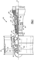
- FIG. 1 schematically illustrates a gas turbine engine 20.
- the gas turbine engine 20 is disclosed herein as a two-spool turbofan that generally incorporates a fan section 22, a compressor section 24, a combustor section 26 and a turbine section 28.
- Alternative engines might include an augmentor section (not shown) among other systems or features.
- the fan section 22 drives air along a bypass flowpath B while the compressor section 24 drives air along a core flowpath C for compression and communication into the combustor section 26 then expansion through the turbine section 28.
- FIG. 1 schematically illustrates a gas turbine engine 20.
- the gas turbine engine 20 is disclosed herein as a two-spool turbofan that generally incorporates a fan section 22, a compressor section 24, a combustor section 26 and a turbine section 28.
- Alternative engines might include an augmentor section (not shown) among other systems or features.
- the fan section 22 drives air along a bypass flowpath B while the compressor section 24 drives air along a core flowpath C for compression and communication into the comb
- the engine 20 generally includes a low speed spool 30 and a high speed spool 32 mounted for rotation about an engine central longitudinal axis A relative to an engine static structure 36 via several bearing systems 38. It should be understood that various bearing systems 38 at various locations may alternatively or additionally be provided.
- the low speed spool 30 generally includes an inner shaft 40 that interconnects a fan 42, a low pressure (or first) compressor section 44 and a low pressure (or first) turbine section 46.
- the inner shaft 40 is connected to the fan 42 through a geared architecture 48 to drive the fan 42 at a lower speed than the low speed spool 30.
- the high speed spool 32 includes an outer shaft 50 that interconnects a high pressure (or second) compressor section 52 and high pressure (or second) turbine section 54.
- a combustor 56 is arranged between the high pressure compressor 52 and the high pressure turbine 54.
- a mid-turbine frame 57 of the engine static structure 36 is arranged generally between the high pressure turbine 54 and the low pressure turbine 46.
- the mid-turbine frame 57 supports one or more bearing systems 38 in the turbine section 28.
- the inner shaft 40 and the outer shaft 50 are concentric and rotate via bearing systems 38 about the engine central longitudinal axis A, which is collinear with their longitudinal axes.
- a "high pressure" compressor or turbine experiences a higher pressure than a corresponding "low pressure” compressor or turbine.
- the core airflow C is compressed by the low pressure compressor 44 then the high pressure compressor 52, mixed and burned with fuel in the combustor 56, then expanded over the high pressure turbine 54 and low pressure turbine 46.
- the mid-turbine frame 57 includes airfoils 59 which are in the core airflow path.
- the turbines 46, 54 rotationally drive the respective low speed spool 30 and high speed spool 32 in response to the expansion.
- the engine 20 in one example is a high-bypass geared aircraft engine.
- the engine 20 bypass ratio is greater than about six (6), with an example embodiment being greater than ten (10)
- the geared architecture 48 is an epicyclic gear train, such as a star gear system or other gear system, with a gear reduction ratio of greater than about 2.3 and the low pressure turbine 46 has a pressure ratio that is greater than about 5.
- the engine 20 bypass ratio is greater than about ten (10:1)
- the fan diameter is significantly larger than that of the low pressure compressor 44
- the low pressure turbine 46 has a pressure ratio that is greater than about 5:1.
- Low pressure turbine 46 pressure ratio is pressure measured prior to inlet of low pressure turbine 46 as related to the pressure at the outlet of the low pressure turbine 46 prior to an exhaust nozzle. It should be understood, however, that the above parameters are only exemplary of one embodiment of a geared architecture engine and that the present invention is applicable to other gas turbine engines including direct drive turbofans.
- the fan section 22 of the engine 20 is designed for a particular flight condition -- typically cruise at about 0.8 Mach and about 35,000 feet (10.7 km).
- the flight condition of 0.8 Mach and 35,000 ft (10.7 km), with the engine at its best fuel consumption - also known as "bucket cruise Thrust Specific Fuel Consumption ('TSFC')" - is the industry standard parameter of lbm of fuel being burned per hour divided by lbf of thrust the engine produces at that minimum point.
- 'TSFC' Thrust Specific Fuel Consumption
- Fan pressure ratio is the pressure ratio across the fan blade alone, without a Fan Exit Guide Vane (“FEGV”) system.
- the low fan pressure ratio as disclosed herein according to one non-limiting embodiment is less than about 1.45.
- the "Low corrected fan tip speed” as disclosed herein according to one non-limiting embodiment is less than about 1150 ft / second (351 m/s).
- a fan shaft 60 interconnects the geared architecture 48 to the fan 42.
- the fan shaft 60 is supported by a pair of bearings 38, which are tapered roller bearings in one example.
- the bearings normally limit the axial travel of the fan shaft 60 and fan 42.
- the engine 20 may experience extreme events such as a fan blade loss or a failure of a fan shaft bearing support 62 supporting the bearings 38, which is part of the engine static structure 36.
- the fan 42 may undesirably tend to move axially forward relative to the other portions of the engine 20, such that the fan 42 and associated components could become disengaged from the engine 20.
- the example engine 20 includes other features that limit movement of the fan 42 during an extreme event, particularly if the bearings 38 or bearing support 62 are ineffective.
- the example engine 20 includes a geared architecture support assembly 64 that limits forward movement of the fan 42 and the geared architecture 48 during an extreme event.
- the example support assembly 64 includes at least a first member 66 and a second member 68.
- the first member 66 and the second member 68 are respectively operatively connected to the geared architecture 48 and the engine static structure 36, which functions as a mechanical ground.
- a compliant flex support 70 mounts the geared architecture 48 to the engine static structure 36.
- the first member 66 and the second member 68 are both arranged axially aft the geared architecture 48 relative to a direction of flow through the engine 20.
- the first and second members 66, 68 are spaced apart from one another providing a gap 72, as shown in Figure 2A .
- the geared architecture 48 may experience an extreme load in the direction F due to the fan 42 rotating and attempting to move axially forward relative to other portions of the engine 20, as shown in Figure 2B .
- extreme movements of the geared architecture 48 are limited by the cooperation of the first and second members 66, 68 such that the loading in the direction F causes the first and second members 66, 68 to engage one another at area 74. This contact blocks movement of the geared architecture 48 axially forward. Since the geared architecture 48 is connected to the fan 42, limiting movement of the geared architecture 48 may prevent the fan 42 from moving axially forward the remaining attached portions of the engine 20.
- One example support assembly 64 is illustrated schematically in Figure 3 .
- the flex support 70 is secured to a carrier 81 by a torque frame 82.
- a lubrication manifold 78 is arranged axially between the carrier 81 and the flex support 70.
- a geartrain 84 of the geared architecture 48 is supported by the torque frame 82.
- the geartrain 84 is a planetary gear arrangement in which planetary gears are supported by the carrier 81 and fixed against rotation by torque frame 82.
- a central sun gear receives rotational drive from the inner shaft 40 ( Figure 1 ) and a ring gear rotationally drives the fan 42 through the fan shaft 60 ( Figure 1 ).
- the flex support 70 includes a bellow 89, which is provided by a wall that doubles back on itself to provide an undulation.
- the bellow 89 accommodates a relative movement of the geared architecture 48 relative to the engine static structure 36.
- An annular mounting flange 91 at an end opposite the bellow 89 is rotationally fixed relative to the engine static structure 36 by fasteners, splines and/or other means.
- the support assembly 64 is provided by sets of first and second members 66, 68, which are removably secured respectively to the flex support 70 and the lubrication manifold 78.
- the first and second members 66, 68 are provided by U-shaped brackets oriented in opposite radial positions from one another to facilitate assembly.
- each set of members include five circumferentially spaced brackets.
- the support assembly 64 may be retrofitted to existing gas turbine engines with geared architectures.
- first and second machined surfaces 86, 88 are respectively provided on the flex support 70 and a back side 87 of the lubrication manifold 78. If these machined surfaces are not provided on existing parts, the manufacturer can mill these surfaces, for example, as part of the retrofitting process.
- First fasteners 90 secure the first member 66 to the end 91.
- Second fasteners 92 secure the second member 68 to the lubrication manifold 78 and carrier 81.
- Existing geared architectures may be retrofitted by replacing the pre-existing fasteners that secure the lubrication manifold 78 to the carrier 81 with longer fasteners while reusing existing holes in the carrier 81 and the lubrication manifold 78.
- the first and second fasteners 90, 92 are threaded fasteners in one example.
- Each first member 66 is provided by spaced apart legs 94 joined by a bend 96.
- each second member 68 is provided by spaced apart legs 98 joined by a bend 100.
- the legs 94, 98 are axially spaced from one another to provide the gap 72 during normal operation.
- the lubrication manifold 78 may include integrally formed lubrication passages 79 that are cast into the lubrication manifold 78 to provide a unitary structure.
- the second members 68 include a second flange 104 supporting a leg 98 and secured to an outer periphery of the lubrication manifold. Alternately, the second member 68 could be secured directly to the carrier 81 through windows or scallops 76 in the lubrication manifold 78.
- the first member 66 includes a first flange 102 supporting a leg 94 and secured to the annular mounting flange 91 of the flex support 70.
- first and second members 66, 68 respectively are secured to the flex support 70 and the lubrication manifold 78.
- the lubrication manifold 78 is arranged in a first angular position 106, illustrated in Figures 6A and 6B , such that the first and second members 66, 68 are circumferentially adjacent to one another but misaligned.
- the lubrication manifold 78 is rotated relative to the flex support 70 to circumferentially align the first and second members 66, 68 relative to one another in a second angular position 108.
- the first member 66 includes a brace 110 to strengthen the axial retention of the member.
- the annular rotation is limited by existing features, which are machined into the torque frame 82 and the flex support 70.
- Features of the disclosed examples include a support structure that permits some movement of a geared architecture relative to other portions of an engine during normal operation of the engine, but limits movements during extreme events, particularly axially forward movements of the geared architecture.
Description
- This disclosure relates to limiting axial movement of a geared architecture within a turbomachine during an extreme event.
- Turbomachines, such as gas turbine engines, typically include a fan section, a turbine section, a compressor section, and a combustor section. Turbomachines may employ a geared architecture connecting the fan section and the turbine section.
- Support structures are used to hold the geared architecture within the turbomachine. The support structures may be relatively compliant to accommodate some movement of the geared architecture relative to other portions of the turbomachine. Extreme engine events such as fan blade loss or failure of fan shaft bearing supports may encourage significant axial movement of the geared architecture and the fan, relative to other portions of the turbomachine. These movements are undesirable as is known. The relatively compliant support structures may not provide desired axial retention of the geared architecture during extreme engine events.
- A prior art support assembly for a geared architecture having the features of the preamble to claim 1 is disclosed in
US 2010/0105516 . - In one exemplary embodiment, a support assembly for a geared architecture includes an engine static structure. A flex support is secured to the engine static structure and includes a bellow. A support structure is operatively secured to the flex support. A geared architecture is mounted to the support structure. First members are removably secured to one of the engine static structure and the flex support and second members are removably secured to the support structure. The first and second members are circumferentially aligned with one another and spaced apart from one another during a normal operating condition. The first and second members are configured to be engageable with one another during an extreme event to limit forward axial movement of the geared architecture relative to the engine static structure.
- In a further embodiment of any of the above, the flex support includes an end opposite the bellow. The first members are removably secured to the end.
- In a further embodiment of any of the above, the end is an annular mounting flange.
- In a further embodiment of any of the above, the support structure includes a torque frame and a carrier. The second members are removably secured to at least one of the torque frame and the carrier.
- In a further embodiment of any of the above, the support structure includes a lubrication manifold. The second members are removably secured to the carrier and the lubrication manifold.
- In a further embodiment of any of the above, the lubrication manifold is arranged axially between the carrier and the second member, engaging the lubrication manifold.
- In a further embodiment of any of the above, threaded fasteners removably secure the first and second members to the flex support and the support structure.
- In one exemplary embodiment, a method of retrofitting a support assembly to a gas turbine engine having a geared architecture includes the steps of providing attachment features in first and second structures, securing first and second members respectively to the first and second structures arranging the first and second members in axially spaced relation to one another in an installed condition, and installing the first structure onto an engine static structure and a geared architecture onto the second structure, wherein the first and second members are configured to be engageable with one another during an extreme event to limit forward axial movement of the geared architecture relative to the engine static structure.
- In a further embodiment of any of the above, the attachment feature providing step includes providing machined surfaces on the first and second structures.
- In a further embodiment of any of the above, the first structure is a flex support having a bellow and an annular mounting flange opposite the bellow. The securing step includes mounting the first members to the annular mounting flange.
- In a further embodiment of any of the above, the securing step includes mounting a lubrication manifold onto the second structure and securing the second members over the oil manifold.
- In a further embodiment of any of the above, the installing step includes securing a torque frame to the flex support and a carrier. The carrier supports the geared architecture.
- In a further embodiment of any of the above, the arranging step includes positioning the first and second members in a first angular position relative to one another, and rotating the first and second members from the first angular position to a second angular position against a stop.
- In a further embodiment of any of the above, the securing steps include tightening threaded fasteners.
- In a further embodiment of any of the above, the securing step relating to the second members includes selecting fasteners having a length longer than a length of pre-exiting fasteners at the attachment feature, which are removed during retrofitting.
- The disclosure can be further understood by reference to the following detailed description when considered in connection with the accompanying drawings wherein:
-
Figure 1 shows a partial section view of an example gas turbine engine. -
Figure 2A depicts a highly schematic view of an example geared architecture support assembly of theFigure 1 gas turbine engine during normal operation. -
Figure 2B depicts a highly schematic view of theFigure 2A geared architecture support during an extreme event. -
Figure 3 is a cross-sectional view of a geared architecture and an example support assembly during normal operation. -
Figure 4 is a rear view of an example oil manifold of the support assembly. -
Figure 5 is a front view of an example flex support of the support assembly. -
Figure 6A is a front view of the oil manifold and flex support in a first angular position during assembly. -
Figure 6B is a top elevational view of the support assembly in the first angular position. -
Figure 7 is a front view of the oil manifold and flex support in a second angular position after assembly. -
Figure 1 schematically illustrates agas turbine engine 20. Thegas turbine engine 20 is disclosed herein as a two-spool turbofan that generally incorporates afan section 22, acompressor section 24, acombustor section 26 and aturbine section 28. Alternative engines might include an augmentor section (not shown) among other systems or features. Thefan section 22 drives air along a bypass flowpath B while thecompressor section 24 drives air along a core flowpath C for compression and communication into thecombustor section 26 then expansion through theturbine section 28. Although depicted as a turbofan gas turbine engine in the disclosed non-limiting embodiment, it should be understood that the concepts described herein are not limited to use with turbofans as the teachings may be applied to other types of turbine engines including three-spool architectures. - The
engine 20 generally includes alow speed spool 30 and ahigh speed spool 32 mounted for rotation about an engine central longitudinal axis A relative to an enginestatic structure 36 viaseveral bearing systems 38. It should be understood thatvarious bearing systems 38 at various locations may alternatively or additionally be provided. - The
low speed spool 30 generally includes aninner shaft 40 that interconnects afan 42, a low pressure (or first) compressor section 44 and a low pressure (or first)turbine section 46. Theinner shaft 40 is connected to thefan 42 through a gearedarchitecture 48 to drive thefan 42 at a lower speed than thelow speed spool 30. Thehigh speed spool 32 includes anouter shaft 50 that interconnects a high pressure (or second)compressor section 52 and high pressure (or second)turbine section 54. Acombustor 56 is arranged between thehigh pressure compressor 52 and thehigh pressure turbine 54. Amid-turbine frame 57 of the enginestatic structure 36 is arranged generally between thehigh pressure turbine 54 and thelow pressure turbine 46. Themid-turbine frame 57 supports one or more bearingsystems 38 in theturbine section 28. Theinner shaft 40 and theouter shaft 50 are concentric and rotate viabearing systems 38 about the engine central longitudinal axis A, which is collinear with their longitudinal axes. As used herein, a "high pressure" compressor or turbine experiences a higher pressure than a corresponding "low pressure" compressor or turbine. - The core airflow C is compressed by the low pressure compressor 44 then the
high pressure compressor 52, mixed and burned with fuel in thecombustor 56, then expanded over thehigh pressure turbine 54 andlow pressure turbine 46. Themid-turbine frame 57 includesairfoils 59 which are in the core airflow path. Theturbines low speed spool 30 andhigh speed spool 32 in response to the expansion. - The
engine 20 in one example is a high-bypass geared aircraft engine. In a further example, theengine 20 bypass ratio is greater than about six (6), with an example embodiment being greater than ten (10), the gearedarchitecture 48 is an epicyclic gear train, such as a star gear system or other gear system, with a gear reduction ratio of greater than about 2.3 and thelow pressure turbine 46 has a pressure ratio that is greater than about 5. In one disclosed embodiment, theengine 20 bypass ratio is greater than about ten (10:1), the fan diameter is significantly larger than that of the low pressure compressor 44, and thelow pressure turbine 46 has a pressure ratio that is greater than about 5:1.Low pressure turbine 46 pressure ratio is pressure measured prior to inlet oflow pressure turbine 46 as related to the pressure at the outlet of thelow pressure turbine 46 prior to an exhaust nozzle. It should be understood, however, that the above parameters are only exemplary of one embodiment of a geared architecture engine and that the present invention is applicable to other gas turbine engines including direct drive turbofans. - A significant amount of thrust is provided by the bypass flow B due to the high bypass ratio. The
fan section 22 of theengine 20 is designed for a particular flight condition -- typically cruise at about 0.8 Mach and about 35,000 feet (10.7 km). The flight condition of 0.8 Mach and 35,000 ft (10.7 km), with the engine at its best fuel consumption - also known as "bucket cruise Thrust Specific Fuel Consumption ('TSFC')" - is the industry standard parameter of lbm of fuel being burned per hour divided by lbf of thrust the engine produces at that minimum point. "Fan pressure ratio" is the pressure ratio across the fan blade alone, without a Fan Exit Guide Vane ("FEGV") system. The low fan pressure ratio as disclosed herein according to one non-limiting embodiment is less than about 1.45. "Low corrected fan tip speed" is the actual fan tip speed in ft/sec divided by an industry standard temperature correction of [(Tambient deg R) / 518.7)^0.5] (°R= °K x 9/5). The "Low corrected fan tip speed" as disclosed herein according to one non-limiting embodiment is less than about 1150 ft / second (351 m/s). - A
fan shaft 60 interconnects the gearedarchitecture 48 to thefan 42. Thefan shaft 60 is supported by a pair ofbearings 38, which are tapered roller bearings in one example. The bearings normally limit the axial travel of thefan shaft 60 andfan 42. During operation, theengine 20 may experience extreme events such as a fan blade loss or a failure of a fanshaft bearing support 62 supporting thebearings 38, which is part of the enginestatic structure 36. In such events, thefan 42 may undesirably tend to move axially forward relative to the other portions of theengine 20, such that thefan 42 and associated components could become disengaged from theengine 20. - Referring to
Figures 2A and 2B with continuing reference toFigure 1 , theexample engine 20 includes other features that limit movement of thefan 42 during an extreme event, particularly if thebearings 38 or bearingsupport 62 are ineffective. For example, theexample engine 20 includes a gearedarchitecture support assembly 64 that limits forward movement of thefan 42 and the gearedarchitecture 48 during an extreme event. - The
example support assembly 64 includes at least afirst member 66 and asecond member 68. Thefirst member 66 and thesecond member 68 are respectively operatively connected to the gearedarchitecture 48 and the enginestatic structure 36, which functions as a mechanical ground. Acompliant flex support 70 mounts the gearedarchitecture 48 to the enginestatic structure 36. In the example, thefirst member 66 and thesecond member 68 are both arranged axially aft the gearedarchitecture 48 relative to a direction of flow through theengine 20. - During normal engine operation, the first and
second members gap 72, as shown inFigure 2A . During an extreme event, such as a blade loss, the gearedarchitecture 48 may experience an extreme load in the direction F due to thefan 42 rotating and attempting to move axially forward relative to other portions of theengine 20, as shown inFigure 2B . In such an event, extreme movements of the gearedarchitecture 48 are limited by the cooperation of the first andsecond members second members area 74. This contact blocks movement of the gearedarchitecture 48 axially forward. Since the gearedarchitecture 48 is connected to thefan 42, limiting movement of the gearedarchitecture 48 may prevent thefan 42 from moving axially forward the remaining attached portions of theengine 20. - One
example support assembly 64 is illustrated schematically inFigure 3 . Theflex support 70 is secured to acarrier 81 by atorque frame 82. Alubrication manifold 78 is arranged axially between thecarrier 81 and theflex support 70. Ageartrain 84 of the gearedarchitecture 48 is supported by thetorque frame 82. In one example, thegeartrain 84 is a planetary gear arrangement in which planetary gears are supported by thecarrier 81 and fixed against rotation bytorque frame 82. A central sun gear receives rotational drive from the inner shaft 40 (Figure 1 ) and a ring gear rotationally drives thefan 42 through the fan shaft 60 (Figure 1 ). - The
flex support 70 includes abellow 89, which is provided by a wall that doubles back on itself to provide an undulation. Thebellow 89 accommodates a relative movement of the gearedarchitecture 48 relative to the enginestatic structure 36. An annular mountingflange 91 at an end opposite thebellow 89 is rotationally fixed relative to the enginestatic structure 36 by fasteners, splines and/or other means. - In the example illustrated, the
support assembly 64 is provided by sets of first andsecond members flex support 70 and thelubrication manifold 78. The first andsecond members - The
support assembly 64 may be retrofitted to existing gas turbine engines with geared architectures. In one example, first and secondmachined surfaces flex support 70 and aback side 87 of thelubrication manifold 78. If these machined surfaces are not provided on existing parts, the manufacturer can mill these surfaces, for example, as part of the retrofitting process.First fasteners 90 secure thefirst member 66 to theend 91.Second fasteners 92 secure thesecond member 68 to thelubrication manifold 78 andcarrier 81. Existing geared architectures may be retrofitted by replacing the pre-existing fasteners that secure thelubrication manifold 78 to thecarrier 81 with longer fasteners while reusing existing holes in thecarrier 81 and thelubrication manifold 78. The first andsecond fasteners - Each
first member 66 is provided by spaced apartlegs 94 joined by abend 96. Similarly, eachsecond member 68 is provided by spaced apartlegs 98 joined by abend 100. Thelegs gap 72 during normal operation. - Referring to
Figure 4 , thelubrication manifold 78 may include integrally formedlubrication passages 79 that are cast into thelubrication manifold 78 to provide a unitary structure. Thesecond members 68 include asecond flange 104 supporting aleg 98 and secured to an outer periphery of the lubrication manifold. Alternately, thesecond member 68 could be secured directly to thecarrier 81 through windows orscallops 76 in thelubrication manifold 78. Referring toFigure 5 , thefirst member 66 includes afirst flange 102 supporting aleg 94 and secured to the annular mountingflange 91 of theflex support 70. - Referring to
Figures 6A-7 , with the first andsecond members flex support 70 and thelubrication manifold 78. Thelubrication manifold 78 is arranged in a first angular position 106, illustrated inFigures 6A and6B , such that the first andsecond members lubrication manifold 78 is rotated relative to theflex support 70 to circumferentially align the first andsecond members angular position 108. In this example, thefirst member 66 includes abrace 110 to strengthen the axial retention of the member. The annular rotation is limited by existing features, which are machined into thetorque frame 82 and theflex support 70. - Features of the disclosed examples include a support structure that permits some movement of a geared architecture relative to other portions of an engine during normal operation of the engine, but limits movements during extreme events, particularly axially forward movements of the geared architecture.
- Although an example embodiment has been disclosed, a worker of ordinary skill in this art would recognize that certain modifications would come within the scope of the claims. For that reason, the following claims should be studied to determine their true scope and content.
Claims (15)
- A support assembly (64) for a geared architecture (48) comprising:an engine static structure (36);a flex support (70) secured to the engine static structure (36) and including a bellow (89);a support structure operatively secured to the flex support (70);a geared architecture (48) mounted to the support structure; andfirst members (66) removably secured to one of the engine static structure (36) and the flex support (70), and second members (68) removably secured to the support structure, the first and second members (66, 68) circumferentially aligned with one another and spaced apart from one another during a normal operating condition, and characterised in thatthe first and second members (66, 68) are configured to be engageable with one another during an extreme event to limit forward axial movement of the geared architecture (48) relative to the engine static structure (36).
- The support assembly according to claim 1, wherein the flex support (70) includes an end opposite the bellow (89), the first members (66) removably secured to the end.
- The support assembly according to claim 2, wherein the end is an annular mounting flange (91).
- The support assembly according to claim 1, 2 or 3, wherein the support structure includes a torque frame (82) and a carrier (81), the second members (68) is removably secured to at least one of the torque frame (82) and the carrier (81).
- The support assembly according to claim 4, wherein the support structure includes a lubrication manifold (78), the second members (68) removably secured to the carrier (81) and the lubrication manifold (78).
- The support assembly according to claim 5, wherein the lubrication manifold (78) is arranged axially between the carrier (81) and the second member (68), engaging the lubrication manifold (78).
- The support assembly according to any preceding claim, comprising threaded fasteners (90, 92) removably securing the first and second members (60, 68) to the flex support (70) and the support structure.
- A method of retrofitting a support assembly (64) to a gas turbine engine (20) having a geared architecture (48), comprising the steps of:providing attachment features in first and second structures;securing first and second members (66, 68) respectively to the first and second structures;arranging the first and second members (66, 68) in axially spaced relation to one another in an installed condition; and
installing the first structure onto an engine static structure (36) and a geared architecture (48) onto the second structure, wherein the first and second members (66, 68) are engageable with one another during an extreme event to limit forward axial movement of the geared architecture (48) relative to the engine static structure (36). - The method according to claim 8, wherein the attachment feature providing step includes providing machined surfaces (86, 88) on the first and second structures.
- The method according to claim 8 or 9, wherein the first structure is a flex support (70) having a bellow (89) and an annular mounting flange (91) opposite the bellow (89), the securing step includes mounting the first members (66) to the annular mounting flange (91).
- The method according to claim 8, 9 or 10, wherein the securing step includes mounting a lubrication manifold (38) onto the second structure, and securing the second members (68) over the lubrication manifold (78).
- The method according to any of claims 8 to 11, wherein the installing step includes securing a torque frame (82) to the flex support (70) and a carrier (81), the carrier (81) supporting the geared architecture (48).
- The method according to any of claims 8 to 12, wherein the arranging step includes positioning the first and second members (66, 68) in a first angular position relative to one another, and rotating the first and second members (66, 68) from the first angular position to a second angular position against a stop.
- The method according to any of claims 8 to 13, wherein the securing steps include tightening threaded fasteners (90, 92).
- The method according to claim 14, wherein the securing step relating to the second members (68) includes selecting fasteners (92) having a length longer than a length of pre-exiting fasteners at the attachment feature, which are removed during retrofitting.
Applications Claiming Priority (2)
| Application Number | Priority Date | Filing Date | Title |
|---|---|---|---|
| US13/435,353 US8790075B2 (en) | 2012-03-30 | 2012-03-30 | Gas turbine engine geared architecture axial retention arrangement |
| PCT/US2013/033795 WO2014007881A2 (en) | 2012-03-30 | 2013-03-26 | Gas turbine engine geared architecture axial retention arrangement |
Publications (3)
| Publication Number | Publication Date |
|---|---|
| EP2831395A2 EP2831395A2 (en) | 2015-02-04 |
| EP2831395A4 EP2831395A4 (en) | 2015-12-16 |
| EP2831395B1 true EP2831395B1 (en) | 2019-05-01 |
Family
ID=48999663
Family Applications (1)
| Application Number | Title | Priority Date | Filing Date |
|---|---|---|---|
| EP13812614.9A Active EP2831395B1 (en) | 2012-03-30 | 2013-03-26 | Gas turbine engine geared architecture axial retention arrangement and retrofitting method |
Country Status (4)
| Country | Link |
|---|---|
| US (4) | US8790075B2 (en) |
| EP (1) | EP2831395B1 (en) |
| SG (1) | SG11201404966QA (en) |
| WO (1) | WO2014007881A2 (en) |
Families Citing this family (11)
| Publication number | Priority date | Publication date | Assignee | Title |
|---|---|---|---|---|
| US8790075B2 (en) * | 2012-03-30 | 2014-07-29 | United Technologies Corporation | Gas turbine engine geared architecture axial retention arrangement |
| US10221771B2 (en) * | 2014-09-24 | 2019-03-05 | United Technologies Corporation | Fan drive gear system |
| GB201510050D0 (en) | 2015-06-10 | 2015-07-22 | Rolls Royce Plc | A geared gas turbine engine |
| US10495004B2 (en) | 2015-09-17 | 2019-12-03 | General Electric Company | Multi-directional gearbox deflection limiter for a gas turbine engine |
| US10107378B2 (en) | 2015-11-03 | 2018-10-23 | General Electric Company | Systems and methods for a gas turbine engine with combined multi-directional gearbox deflection limiters and dampers |
| US10655728B2 (en) * | 2015-12-01 | 2020-05-19 | The Boeing Company | Reconfigurable lubrication system for tiltrotor transmission |
| US10066734B2 (en) * | 2015-12-07 | 2018-09-04 | United Technologies Corporation | Gear driven gas turbine engine assembly |
| US10087849B2 (en) * | 2016-04-08 | 2018-10-02 | United Technologies Corporation | Retention device for speed change mechanism in a gas turbine engine |
| DE102017109940A1 (en) * | 2017-05-09 | 2018-11-15 | Rolls-Royce Deutschland Ltd & Co Kg | Turbofan |
| GB2583129A (en) * | 2019-04-18 | 2020-10-21 | Rolls Royce Plc | A shaft catcher system |
| US11492924B1 (en) * | 2021-04-26 | 2022-11-08 | General Electric Company Polska sp. z o.o | Embedded electric machine cooling |
Family Cites Families (78)
| Publication number | Priority date | Publication date | Assignee | Title |
|---|---|---|---|---|
| US2258792A (en) | 1941-04-12 | 1941-10-14 | Westinghouse Electric & Mfg Co | Turbine blading |
| US3021731A (en) | 1951-11-10 | 1962-02-20 | Wilhelm G Stoeckicht | Planetary gear transmission |
| US2936655A (en) | 1955-11-04 | 1960-05-17 | Gen Motors Corp | Self-aligning planetary gearing |
| US3194487A (en) | 1963-06-04 | 1965-07-13 | United Aircraft Corp | Noise abatement method and apparatus |
| US3287906A (en) | 1965-07-20 | 1966-11-29 | Gen Motors Corp | Cooled gas turbine vanes |
| US3352178A (en) | 1965-11-15 | 1967-11-14 | Gen Motors Corp | Planetary gearing |
| US3412560A (en) | 1966-08-03 | 1968-11-26 | Gen Motors Corp | Jet propulsion engine with cooled combustion chamber, fuel heater, and induced air-flow |
| GB1350431A (en) | 1971-01-08 | 1974-04-18 | Secr Defence | Gearing |
| US3892358A (en) | 1971-03-17 | 1975-07-01 | Gen Electric | Nozzle seal |
| US3747343A (en) | 1972-02-10 | 1973-07-24 | United Aircraft Corp | Low noise prop-fan |
| GB1418905A (en) | 1972-05-09 | 1975-12-24 | Rolls Royce | Gas turbine engines |
| US3988889A (en) | 1974-02-25 | 1976-11-02 | General Electric Company | Cowling arrangement for a turbofan engine |
| US3932058A (en) | 1974-06-07 | 1976-01-13 | United Technologies Corporation | Control system for variable pitch fan propulsor |
| US3935558A (en) | 1974-12-11 | 1976-01-27 | United Technologies Corporation | Surge detector for turbine engines |
| US4130872A (en) | 1975-10-10 | 1978-12-19 | The United States Of America As Represented By The Secretary Of The Air Force | Method and system of controlling a jet engine for avoiding engine surge |
| GB1516041A (en) | 1977-02-14 | 1978-06-28 | Secr Defence | Multistage axial flow compressor stators |
| GB2041090A (en) | 1979-01-31 | 1980-09-03 | Rolls Royce | By-pass gas turbine engines |
| US4284174A (en) | 1979-04-18 | 1981-08-18 | Avco Corporation | Emergency oil/mist system |
| DE2940446C2 (en) | 1979-10-05 | 1982-07-08 | B. Braun Melsungen Ag, 3508 Melsungen | Cultivation of animal cells in suspension and monolayer cultures in fermentation vessels |
| US4478551A (en) | 1981-12-08 | 1984-10-23 | United Technologies Corporation | Turbine exhaust case design |
| US4696156A (en) | 1986-06-03 | 1987-09-29 | United Technologies Corporation | Fuel and oil heat management system for a gas turbine engine |
| US4979362A (en) | 1989-05-17 | 1990-12-25 | Sundstrand Corporation | Aircraft engine starting and emergency power generating system |
| US5141400A (en) | 1991-01-25 | 1992-08-25 | General Electric Company | Wide chord fan blade |
| US5102379A (en) | 1991-03-25 | 1992-04-07 | United Technologies Corporation | Journal bearing arrangement |
| US5317877A (en) | 1992-08-03 | 1994-06-07 | General Electric Company | Intercooled turbine blade cooling air feed system |
| US5447411A (en) | 1993-06-10 | 1995-09-05 | Martin Marietta Corporation | Light weight fan blade containment system |
| US5466198A (en) | 1993-06-11 | 1995-11-14 | United Technologies Corporation | Geared drive system for a bladed propulsor |
| US5524847A (en) | 1993-09-07 | 1996-06-11 | United Technologies Corporation | Nacelle and mounting arrangement for an aircraft engine |
| RU2082824C1 (en) | 1994-03-10 | 1997-06-27 | Московский государственный авиационный институт (технический университет) | Method of protection of heat-resistant material from effect of high-rapid gaseous flow of corrosive media (variants) |
| US5433674A (en) * | 1994-04-12 | 1995-07-18 | United Technologies Corporation | Coupling system for a planetary gear train |
| US5778659A (en) | 1994-10-20 | 1998-07-14 | United Technologies Corporation | Variable area fan exhaust nozzle having mechanically separate sleeve and thrust reverser actuation systems |
| US5915917A (en) | 1994-12-14 | 1999-06-29 | United Technologies Corporation | Compressor stall and surge control using airflow asymmetry measurement |
| JP2969075B2 (en) | 1996-02-26 | 1999-11-02 | ジャパンゴアテックス株式会社 | Degassing device |
| US6183388B1 (en) | 1996-03-12 | 2001-02-06 | Allison Engine Company, Inc. | Epicyclic face gear reduction gearbox particularly for a gas turbine engine |
| US5857836A (en) | 1996-09-10 | 1999-01-12 | Aerodyne Research, Inc. | Evaporatively cooled rotor for a gas turbine engine |
| US5975841A (en) | 1997-10-03 | 1999-11-02 | Thermal Corp. | Heat pipe cooling for turbine stators |
| US5985470A (en) | 1998-03-16 | 1999-11-16 | General Electric Company | Thermal/environmental barrier coating system for silicon-based materials |
| US6517341B1 (en) | 1999-02-26 | 2003-02-11 | General Electric Company | Method to prevent recession loss of silica and silicon-containing materials in combustion gas environments |
| US6410148B1 (en) | 1999-04-15 | 2002-06-25 | General Electric Co. | Silicon based substrate with environmental/ thermal barrier layer |
| US6315815B1 (en) | 1999-12-16 | 2001-11-13 | United Technologies Corporation | Membrane based fuel deoxygenator |
| US6223616B1 (en) | 1999-12-22 | 2001-05-01 | United Technologies Corporation | Star gear system with lubrication circuit and lubrication method therefor |
| US6318070B1 (en) | 2000-03-03 | 2001-11-20 | United Technologies Corporation | Variable area nozzle for gas turbine engines driven by shape memory alloy actuators |
| US6444335B1 (en) | 2000-04-06 | 2002-09-03 | General Electric Company | Thermal/environmental barrier coating for silicon-containing materials |
| US6663530B2 (en) | 2001-12-14 | 2003-12-16 | Pratt & Whitney Canada Corp. | Zero twist carrier |
| US6607165B1 (en) | 2002-06-28 | 2003-08-19 | General Electric Company | Aircraft engine mount with single thrust link |
| US6814541B2 (en) | 2002-10-07 | 2004-11-09 | General Electric Company | Jet aircraft fan case containment design |
| US7021042B2 (en) | 2002-12-13 | 2006-04-04 | United Technologies Corporation | Geartrain coupling for a turbofan engine |
| DE10307221A1 (en) * | 2003-02-20 | 2004-09-02 | Zf Friedrichshafen Ag | planet |
| US6709492B1 (en) | 2003-04-04 | 2004-03-23 | United Technologies Corporation | Planar membrane deoxygenator |
| DE102004016246A1 (en) | 2004-04-02 | 2005-10-20 | Mtu Aero Engines Gmbh | Turbine, in particular low-pressure turbine, a gas turbine, in particular an aircraft engine |
| US7328580B2 (en) | 2004-06-23 | 2008-02-12 | General Electric Company | Chevron film cooled wall |
| WO2006110125A2 (en) | 2004-12-01 | 2006-10-19 | United Technologies Corporation | Stacked annular components for turbine engines |
| GB0506685D0 (en) | 2005-04-01 | 2005-05-11 | Hopkins David R | A design to increase and smoothly improve the throughput of fluid (air or gas) through the inlet fan (or fans) of an aero-engine system |
| US7374403B2 (en) | 2005-04-07 | 2008-05-20 | General Electric Company | Low solidity turbofan |
| EP1928943B1 (en) | 2005-09-28 | 2014-07-09 | Entrotech Composites, LLC. | Linerless prepregs, composite articles therefrom, and related methods |
| US7591754B2 (en) | 2006-03-22 | 2009-09-22 | United Technologies Corporation | Epicyclic gear train integral sun gear coupling design |
| US20080003096A1 (en) | 2006-06-29 | 2008-01-03 | United Technologies Corporation | High coverage cooling hole shape |
| US8585538B2 (en) | 2006-07-05 | 2013-11-19 | United Technologies Corporation | Coupling system for a star gear train in a gas turbine engine |
| US7926260B2 (en) | 2006-07-05 | 2011-04-19 | United Technologies Corporation | Flexible shaft for gas turbine engine |
| US7694505B2 (en) | 2006-07-31 | 2010-04-13 | General Electric Company | Gas turbine engine assembly and method of assembling same |
| US7662059B2 (en) | 2006-10-18 | 2010-02-16 | United Technologies Corporation | Lubrication of windmilling journal bearings |
| US8020665B2 (en) | 2006-11-22 | 2011-09-20 | United Technologies Corporation | Lubrication system with extended emergency operability |
| US7621843B2 (en) * | 2007-01-17 | 2009-11-24 | General Electric Company | Apparatus for restraining axial movement of a ring gear in a gearbox for a wind turbine |
| US8017188B2 (en) | 2007-04-17 | 2011-09-13 | General Electric Company | Methods of making articles having toughened and untoughened regions |
| US7950237B2 (en) | 2007-06-25 | 2011-05-31 | United Technologies Corporation | Managing spool bearing load using variable area flow nozzle |
| US20120124964A1 (en) | 2007-07-27 | 2012-05-24 | Hasel Karl L | Gas turbine engine with improved fuel efficiency |
| US8256707B2 (en) | 2007-08-01 | 2012-09-04 | United Technologies Corporation | Engine mounting configuration for a turbofan gas turbine engine |
| US8205432B2 (en) | 2007-10-03 | 2012-06-26 | United Technologies Corporation | Epicyclic gear train for turbo fan engine |
| US8128021B2 (en) * | 2008-06-02 | 2012-03-06 | United Technologies Corporation | Engine mount system for a turbofan gas turbine engine |
| US7997868B1 (en) | 2008-11-18 | 2011-08-16 | Florida Turbine Technologies, Inc. | Film cooling hole for turbine airfoil |
| US8307626B2 (en) | 2009-02-26 | 2012-11-13 | United Technologies Corporation | Auxiliary pump system for fan drive gear system |
| US8181441B2 (en) | 2009-02-27 | 2012-05-22 | United Technologies Corporation | Controlled fan stream flow bypass |
| US8172716B2 (en) | 2009-06-25 | 2012-05-08 | United Technologies Corporation | Epicyclic gear system with superfinished journal bearing |
| US8672801B2 (en) | 2009-11-30 | 2014-03-18 | United Technologies Corporation | Mounting system for a planetary gear train in a gas turbine engine |
| US9170616B2 (en) | 2009-12-31 | 2015-10-27 | Intel Corporation | Quiet system cooling using coupled optimization between integrated micro porous absorbers and rotors |
| US8845277B2 (en) | 2010-05-24 | 2014-09-30 | United Technologies Corporation | Geared turbofan engine with integral gear and bearing supports |
| US8905713B2 (en) | 2010-05-28 | 2014-12-09 | General Electric Company | Articles which include chevron film cooling holes, and related processes |
| US8790075B2 (en) * | 2012-03-30 | 2014-07-29 | United Technologies Corporation | Gas turbine engine geared architecture axial retention arrangement |
-
2012
- 2012-03-30 US US13/435,353 patent/US8790075B2/en active Active
- 2012-07-25 US US13/557,491 patent/US8517670B1/en active Active
-
2013
- 2013-03-26 EP EP13812614.9A patent/EP2831395B1/en active Active
- 2013-03-26 WO PCT/US2013/033795 patent/WO2014007881A2/en active Application Filing
- 2013-03-26 SG SG11201404966QA patent/SG11201404966QA/en unknown
-
2014
- 2014-06-17 US US14/306,402 patent/US9664114B2/en active Active
-
2017
- 2017-04-26 US US15/497,590 patent/US10436116B2/en active Active
Non-Patent Citations (1)
| Title |
|---|
| None * |
Also Published As
| Publication number | Publication date |
|---|---|
| US10436116B2 (en) | 2019-10-08 |
| US20130259657A1 (en) | 2013-10-03 |
| EP2831395A4 (en) | 2015-12-16 |
| US20140290268A1 (en) | 2014-10-02 |
| US20170298828A1 (en) | 2017-10-19 |
| WO2014007881A3 (en) | 2014-08-28 |
| US8790075B2 (en) | 2014-07-29 |
| US9664114B2 (en) | 2017-05-30 |
| EP2831395A2 (en) | 2015-02-04 |
| WO2014007881A2 (en) | 2014-01-09 |
| US8517670B1 (en) | 2013-08-27 |
| SG11201404966QA (en) | 2014-11-27 |
Similar Documents
| Publication | Publication Date | Title |
|---|---|---|
| US10436116B2 (en) | Gas turbine engine geared architecture axial retention arrangement | |
| EP2809891B1 (en) | Gas turbine engine mid turbine frame bearing support | |
| EP2809914B1 (en) | Gas turbine engine shaft bearing configuration | |
| EP2809890B1 (en) | Gas turbine engine bearing arrangement | |
| EP2809889B1 (en) | Turbomachine geared architecture support assembly | |
| EP2852744B1 (en) | Shield system for gas turbine engine | |
| EP3489472B1 (en) | Gas turbine engine front center body architecture | |
| WO2014137574A1 (en) | Mid-turbine frame rod and turbine case flange | |
| EP2880282B1 (en) | Compressor assembly with stator anti-rotation lug | |
| EP2855887B1 (en) | Turbomachine geared architecture support assembly | |
| EP2809937B1 (en) | Gas turbine engine shaft bearing arrangement | |
| EP2971578B1 (en) | Method of assembling a gas turbine engine front architecture and corresponding gas turbine engine front architecture | |
| EP2932072B1 (en) | Fan drive gear system assembly guide | |
| EP3004598A2 (en) | Spline ring for a fan drive gear flexible support | |
| EP3081768B1 (en) | Gas turbine engine shaft bearing configuration | |
| EP3404215B1 (en) | Gas turbine engine with seal anti-rotation lock | |
| US10145264B2 (en) | Variable vane actuation system | |
| EP3011139B1 (en) | Unitary one piece gas turbine hub |
Legal Events
| Date | Code | Title | Description |
|---|---|---|---|
| PUAI | Public reference made under article 153(3) epc to a published international application that has entered the european phase |
Free format text: ORIGINAL CODE: 0009012 |
|
| 17P | Request for examination filed |
Effective date: 20141028 |
|
| AK | Designated contracting states |
Kind code of ref document: A2 Designated state(s): AL AT BE BG CH CY CZ DE DK EE ES FI FR GB GR HR HU IE IS IT LI LT LU LV MC MK MT NL NO PL PT RO RS SE SI SK SM TR |
|
| AX | Request for extension of the european patent |
Extension state: BA ME |
|
| DAX | Request for extension of the european patent (deleted) | ||
| A4 | Supplementary search report drawn up and despatched |
Effective date: 20151112 |
|
| RIC1 | Information provided on ipc code assigned before grant |
Ipc: B23P 6/00 20060101ALI20151106BHEP Ipc: F01D 15/12 20060101ALI20151106BHEP Ipc: F02C 7/36 20060101AFI20151106BHEP |
|
| RAP1 | Party data changed (applicant data changed or rights of an application transferred) |
Owner name: UNITED TECHNOLOGIES CORPORATION |
|
| GRAP | Despatch of communication of intention to grant a patent |
Free format text: ORIGINAL CODE: EPIDOSNIGR1 |
|
| STAA | Information on the status of an ep patent application or granted ep patent |
Free format text: STATUS: GRANT OF PATENT IS INTENDED |
|
| INTG | Intention to grant announced |
Effective date: 20180926 |
|
| GRAJ | Information related to disapproval of communication of intention to grant by the applicant or resumption of examination proceedings by the epo deleted |
Free format text: ORIGINAL CODE: EPIDOSDIGR1 |
|
| STAA | Information on the status of an ep patent application or granted ep patent |
Free format text: STATUS: REQUEST FOR EXAMINATION WAS MADE |
|
| GRAR | Information related to intention to grant a patent recorded |
Free format text: ORIGINAL CODE: EPIDOSNIGR71 |
|
| GRAS | Grant fee paid |
Free format text: ORIGINAL CODE: EPIDOSNIGR3 |
|
| STAA | Information on the status of an ep patent application or granted ep patent |
Free format text: STATUS: GRANT OF PATENT IS INTENDED |
|
| INTC | Intention to grant announced (deleted) | ||
| INTG | Intention to grant announced |
Effective date: 20190213 |
|
| GRAA | (expected) grant |
Free format text: ORIGINAL CODE: 0009210 |
|
| STAA | Information on the status of an ep patent application or granted ep patent |
Free format text: STATUS: THE PATENT HAS BEEN GRANTED |
|
| AK | Designated contracting states |
Kind code of ref document: B1 Designated state(s): AL AT BE BG CH CY CZ DE DK EE ES FI FR GB GR HR HU IE IS IT LI LT LU LV MC MK MT NL NO PL PT RO RS SE SI SK SM TR |
|
| REG | Reference to a national code |
Ref country code: GB Ref legal event code: FG4D |
|
| REG | Reference to a national code |
Ref country code: CH Ref legal event code: EP Ref country code: AT Ref legal event code: REF Ref document number: 1127227 Country of ref document: AT Kind code of ref document: T Effective date: 20190515 |
|
| REG | Reference to a national code |
Ref country code: DE Ref legal event code: R096 Ref document number: 602013054733 Country of ref document: DE |
|
| REG | Reference to a national code |
Ref country code: IE Ref legal event code: FG4D |
|
| REG | Reference to a national code |
Ref country code: NL Ref legal event code: MP Effective date: 20190501 |
|
| REG | Reference to a national code |
Ref country code: LT Ref legal event code: MG4D |
|
| PG25 | Lapsed in a contracting state [announced via postgrant information from national office to epo] |
Ref country code: ES Free format text: LAPSE BECAUSE OF FAILURE TO SUBMIT A TRANSLATION OF THE DESCRIPTION OR TO PAY THE FEE WITHIN THE PRESCRIBED TIME-LIMIT Effective date: 20190501 Ref country code: NO Free format text: LAPSE BECAUSE OF FAILURE TO SUBMIT A TRANSLATION OF THE DESCRIPTION OR TO PAY THE FEE WITHIN THE PRESCRIBED TIME-LIMIT Effective date: 20190801 Ref country code: PT Free format text: LAPSE BECAUSE OF FAILURE TO SUBMIT A TRANSLATION OF THE DESCRIPTION OR TO PAY THE FEE WITHIN THE PRESCRIBED TIME-LIMIT Effective date: 20190901 Ref country code: SE Free format text: LAPSE BECAUSE OF FAILURE TO SUBMIT A TRANSLATION OF THE DESCRIPTION OR TO PAY THE FEE WITHIN THE PRESCRIBED TIME-LIMIT Effective date: 20190501 Ref country code: AL Free format text: LAPSE BECAUSE OF FAILURE TO SUBMIT A TRANSLATION OF THE DESCRIPTION OR TO PAY THE FEE WITHIN THE PRESCRIBED TIME-LIMIT Effective date: 20190501 Ref country code: HR Free format text: LAPSE BECAUSE OF FAILURE TO SUBMIT A TRANSLATION OF THE DESCRIPTION OR TO PAY THE FEE WITHIN THE PRESCRIBED TIME-LIMIT Effective date: 20190501 Ref country code: NL Free format text: LAPSE BECAUSE OF FAILURE TO SUBMIT A TRANSLATION OF THE DESCRIPTION OR TO PAY THE FEE WITHIN THE PRESCRIBED TIME-LIMIT Effective date: 20190501 Ref country code: FI Free format text: LAPSE BECAUSE OF FAILURE TO SUBMIT A TRANSLATION OF THE DESCRIPTION OR TO PAY THE FEE WITHIN THE PRESCRIBED TIME-LIMIT Effective date: 20190501 Ref country code: LT Free format text: LAPSE BECAUSE OF FAILURE TO SUBMIT A TRANSLATION OF THE DESCRIPTION OR TO PAY THE FEE WITHIN THE PRESCRIBED TIME-LIMIT Effective date: 20190501 |
|
| PG25 | Lapsed in a contracting state [announced via postgrant information from national office to epo] |
Ref country code: LV Free format text: LAPSE BECAUSE OF FAILURE TO SUBMIT A TRANSLATION OF THE DESCRIPTION OR TO PAY THE FEE WITHIN THE PRESCRIBED TIME-LIMIT Effective date: 20190501 Ref country code: BG Free format text: LAPSE BECAUSE OF FAILURE TO SUBMIT A TRANSLATION OF THE DESCRIPTION OR TO PAY THE FEE WITHIN THE PRESCRIBED TIME-LIMIT Effective date: 20190801 Ref country code: RS Free format text: LAPSE BECAUSE OF FAILURE TO SUBMIT A TRANSLATION OF THE DESCRIPTION OR TO PAY THE FEE WITHIN THE PRESCRIBED TIME-LIMIT Effective date: 20190501 Ref country code: GR Free format text: LAPSE BECAUSE OF FAILURE TO SUBMIT A TRANSLATION OF THE DESCRIPTION OR TO PAY THE FEE WITHIN THE PRESCRIBED TIME-LIMIT Effective date: 20190802 |
|
| REG | Reference to a national code |
Ref country code: AT Ref legal event code: MK05 Ref document number: 1127227 Country of ref document: AT Kind code of ref document: T Effective date: 20190501 |
|
| PG25 | Lapsed in a contracting state [announced via postgrant information from national office to epo] |
Ref country code: IS Free format text: LAPSE BECAUSE OF FAILURE TO SUBMIT A TRANSLATION OF THE DESCRIPTION OR TO PAY THE FEE WITHIN THE PRESCRIBED TIME-LIMIT Effective date: 20190901 |
|
| PG25 | Lapsed in a contracting state [announced via postgrant information from national office to epo] |
Ref country code: SK Free format text: LAPSE BECAUSE OF FAILURE TO SUBMIT A TRANSLATION OF THE DESCRIPTION OR TO PAY THE FEE WITHIN THE PRESCRIBED TIME-LIMIT Effective date: 20190501 Ref country code: DK Free format text: LAPSE BECAUSE OF FAILURE TO SUBMIT A TRANSLATION OF THE DESCRIPTION OR TO PAY THE FEE WITHIN THE PRESCRIBED TIME-LIMIT Effective date: 20190501 Ref country code: AT Free format text: LAPSE BECAUSE OF FAILURE TO SUBMIT A TRANSLATION OF THE DESCRIPTION OR TO PAY THE FEE WITHIN THE PRESCRIBED TIME-LIMIT Effective date: 20190501 Ref country code: EE Free format text: LAPSE BECAUSE OF FAILURE TO SUBMIT A TRANSLATION OF THE DESCRIPTION OR TO PAY THE FEE WITHIN THE PRESCRIBED TIME-LIMIT Effective date: 20190501 Ref country code: RO Free format text: LAPSE BECAUSE OF FAILURE TO SUBMIT A TRANSLATION OF THE DESCRIPTION OR TO PAY THE FEE WITHIN THE PRESCRIBED TIME-LIMIT Effective date: 20190501 Ref country code: CZ Free format text: LAPSE BECAUSE OF FAILURE TO SUBMIT A TRANSLATION OF THE DESCRIPTION OR TO PAY THE FEE WITHIN THE PRESCRIBED TIME-LIMIT Effective date: 20190501 |
|
| REG | Reference to a national code |
Ref country code: DE Ref legal event code: R097 Ref document number: 602013054733 Country of ref document: DE |
|
| PG25 | Lapsed in a contracting state [announced via postgrant information from national office to epo] |
Ref country code: SM Free format text: LAPSE BECAUSE OF FAILURE TO SUBMIT A TRANSLATION OF THE DESCRIPTION OR TO PAY THE FEE WITHIN THE PRESCRIBED TIME-LIMIT Effective date: 20190501 Ref country code: IT Free format text: LAPSE BECAUSE OF FAILURE TO SUBMIT A TRANSLATION OF THE DESCRIPTION OR TO PAY THE FEE WITHIN THE PRESCRIBED TIME-LIMIT Effective date: 20190501 |
|
| PLBE | No opposition filed within time limit |
Free format text: ORIGINAL CODE: 0009261 |
|
| STAA | Information on the status of an ep patent application or granted ep patent |
Free format text: STATUS: NO OPPOSITION FILED WITHIN TIME LIMIT |
|
| PG25 | Lapsed in a contracting state [announced via postgrant information from national office to epo] |
Ref country code: TR Free format text: LAPSE BECAUSE OF FAILURE TO SUBMIT A TRANSLATION OF THE DESCRIPTION OR TO PAY THE FEE WITHIN THE PRESCRIBED TIME-LIMIT Effective date: 20190501 |
|
| 26N | No opposition filed |
Effective date: 20200204 |
|
| PG25 | Lapsed in a contracting state [announced via postgrant information from national office to epo] |
Ref country code: PL Free format text: LAPSE BECAUSE OF FAILURE TO SUBMIT A TRANSLATION OF THE DESCRIPTION OR TO PAY THE FEE WITHIN THE PRESCRIBED TIME-LIMIT Effective date: 20190501 |
|
| PG25 | Lapsed in a contracting state [announced via postgrant information from national office to epo] |
Ref country code: SI Free format text: LAPSE BECAUSE OF FAILURE TO SUBMIT A TRANSLATION OF THE DESCRIPTION OR TO PAY THE FEE WITHIN THE PRESCRIBED TIME-LIMIT Effective date: 20190501 |
|
| PG25 | Lapsed in a contracting state [announced via postgrant information from national office to epo] |
Ref country code: MC Free format text: LAPSE BECAUSE OF FAILURE TO SUBMIT A TRANSLATION OF THE DESCRIPTION OR TO PAY THE FEE WITHIN THE PRESCRIBED TIME-LIMIT Effective date: 20190501 |
|
| REG | Reference to a national code |
Ref country code: CH Ref legal event code: PL |
|
| REG | Reference to a national code |
Ref country code: BE Ref legal event code: MM Effective date: 20200331 |
|
| PG25 | Lapsed in a contracting state [announced via postgrant information from national office to epo] |
Ref country code: LU Free format text: LAPSE BECAUSE OF NON-PAYMENT OF DUE FEES Effective date: 20200326 |
|
| PG25 | Lapsed in a contracting state [announced via postgrant information from national office to epo] |
Ref country code: CH Free format text: LAPSE BECAUSE OF NON-PAYMENT OF DUE FEES Effective date: 20200331 Ref country code: LI Free format text: LAPSE BECAUSE OF NON-PAYMENT OF DUE FEES Effective date: 20200331 Ref country code: IE Free format text: LAPSE BECAUSE OF NON-PAYMENT OF DUE FEES Effective date: 20200326 |
|
| PG25 | Lapsed in a contracting state [announced via postgrant information from national office to epo] |
Ref country code: BE Free format text: LAPSE BECAUSE OF NON-PAYMENT OF DUE FEES Effective date: 20200331 |
|
| PG25 | Lapsed in a contracting state [announced via postgrant information from national office to epo] |
Ref country code: MT Free format text: LAPSE BECAUSE OF FAILURE TO SUBMIT A TRANSLATION OF THE DESCRIPTION OR TO PAY THE FEE WITHIN THE PRESCRIBED TIME-LIMIT Effective date: 20190501 Ref country code: CY Free format text: LAPSE BECAUSE OF FAILURE TO SUBMIT A TRANSLATION OF THE DESCRIPTION OR TO PAY THE FEE WITHIN THE PRESCRIBED TIME-LIMIT Effective date: 20190501 |
|
| PG25 | Lapsed in a contracting state [announced via postgrant information from national office to epo] |
Ref country code: MK Free format text: LAPSE BECAUSE OF FAILURE TO SUBMIT A TRANSLATION OF THE DESCRIPTION OR TO PAY THE FEE WITHIN THE PRESCRIBED TIME-LIMIT Effective date: 20190501 |
|
| REG | Reference to a national code |
Ref country code: DE Ref legal event code: R081 Ref document number: 602013054733 Country of ref document: DE Owner name: RAYTHEON TECHNOLOGIES CORPORATION (N.D.GES.D.S, US Free format text: FORMER OWNER: UNITED TECHNOLOGIES CORPORATION, FARMINGTON, CONN., US |
|
| PGFP | Annual fee paid to national office [announced via postgrant information from national office to epo] |
Ref country code: FR Payment date: 20230222 Year of fee payment: 11 |
|
| PGFP | Annual fee paid to national office [announced via postgrant information from national office to epo] |
Ref country code: GB Payment date: 20230222 Year of fee payment: 11 Ref country code: DE Payment date: 20230221 Year of fee payment: 11 |
|
| P01 | Opt-out of the competence of the unified patent court (upc) registered |
Effective date: 20230520 |