EP2831021B1 - Improved controllability oxidative dehydrogenation process for producing butadiene - Google Patents
Improved controllability oxidative dehydrogenation process for producing butadiene Download PDFInfo
- Publication number
- EP2831021B1 EP2831021B1 EP13768548.3A EP13768548A EP2831021B1 EP 2831021 B1 EP2831021 B1 EP 2831021B1 EP 13768548 A EP13768548 A EP 13768548A EP 2831021 B1 EP2831021 B1 EP 2831021B1
- Authority
- EP
- European Patent Office
- Prior art keywords
- catalyst
- oxidative dehydrogenation
- feed
- butadiene
- bed
- Prior art date
- Legal status (The legal status is an assumption and is not a legal conclusion. Google has not performed a legal analysis and makes no representation as to the accuracy of the status listed.)
- Active
Links
Images


Classifications
-
- B—PERFORMING OPERATIONS; TRANSPORTING
- B01—PHYSICAL OR CHEMICAL PROCESSES OR APPARATUS IN GENERAL
- B01J—CHEMICAL OR PHYSICAL PROCESSES, e.g. CATALYSIS OR COLLOID CHEMISTRY; THEIR RELEVANT APPARATUS
- B01J19/00—Chemical, physical or physico-chemical processes in general; Their relevant apparatus
- B01J19/24—Stationary reactors without moving elements inside
-
- C—CHEMISTRY; METALLURGY
- C07—ORGANIC CHEMISTRY
- C07C—ACYCLIC OR CARBOCYCLIC COMPOUNDS
- C07C5/00—Preparation of hydrocarbons from hydrocarbons containing the same number of carbon atoms
- C07C5/42—Preparation of hydrocarbons from hydrocarbons containing the same number of carbon atoms by dehydrogenation with a hydrogen acceptor
- C07C5/48—Preparation of hydrocarbons from hydrocarbons containing the same number of carbon atoms by dehydrogenation with a hydrogen acceptor with oxygen as an acceptor
-
- C—CHEMISTRY; METALLURGY
- C07—ORGANIC CHEMISTRY
- C07C—ACYCLIC OR CARBOCYCLIC COMPOUNDS
- C07C5/00—Preparation of hydrocarbons from hydrocarbons containing the same number of carbon atoms
- C07C5/02—Preparation of hydrocarbons from hydrocarbons containing the same number of carbon atoms by hydrogenation
- C07C5/08—Preparation of hydrocarbons from hydrocarbons containing the same number of carbon atoms by hydrogenation of carbon-to-carbon triple bonds
- C07C5/09—Preparation of hydrocarbons from hydrocarbons containing the same number of carbon atoms by hydrogenation of carbon-to-carbon triple bonds to carbon-to-carbon double bonds
-
- C—CHEMISTRY; METALLURGY
- C07—ORGANIC CHEMISTRY
- C07C—ACYCLIC OR CARBOCYCLIC COMPOUNDS
- C07C7/00—Purification; Separation; Use of additives
- C07C7/005—Processes comprising at least two steps in series
-
- B—PERFORMING OPERATIONS; TRANSPORTING
- B01—PHYSICAL OR CHEMICAL PROCESSES OR APPARATUS IN GENERAL
- B01J—CHEMICAL OR PHYSICAL PROCESSES, e.g. CATALYSIS OR COLLOID CHEMISTRY; THEIR RELEVANT APPARATUS
- B01J2219/00—Chemical, physical or physico-chemical processes in general; Their relevant apparatus
- B01J2219/00049—Controlling or regulating processes
- B01J2219/00051—Controlling the temperature
- B01J2219/00074—Controlling the temperature by indirect heating or cooling employing heat exchange fluids
- B01J2219/00087—Controlling the temperature by indirect heating or cooling employing heat exchange fluids with heat exchange elements outside the reactor
- B01J2219/00103—Controlling the temperature by indirect heating or cooling employing heat exchange fluids with heat exchange elements outside the reactor in a heat exchanger separate from the reactor
-
- B—PERFORMING OPERATIONS; TRANSPORTING
- B01—PHYSICAL OR CHEMICAL PROCESSES OR APPARATUS IN GENERAL
- B01J—CHEMICAL OR PHYSICAL PROCESSES, e.g. CATALYSIS OR COLLOID CHEMISTRY; THEIR RELEVANT APPARATUS
- B01J2219/00—Chemical, physical or physico-chemical processes in general; Their relevant apparatus
- B01J2219/24—Stationary reactors without moving elements inside
-
- B—PERFORMING OPERATIONS; TRANSPORTING
- B01—PHYSICAL OR CHEMICAL PROCESSES OR APPARATUS IN GENERAL
- B01J—CHEMICAL OR PHYSICAL PROCESSES, e.g. CATALYSIS OR COLLOID CHEMISTRY; THEIR RELEVANT APPARATUS
- B01J23/00—Catalysts comprising metals or metal oxides or hydroxides, not provided for in group B01J21/00
- B01J23/70—Catalysts comprising metals or metal oxides or hydroxides, not provided for in group B01J21/00 of the iron group metals or copper
- B01J23/76—Catalysts comprising metals or metal oxides or hydroxides, not provided for in group B01J21/00 of the iron group metals or copper combined with metals, oxides or hydroxides provided for in groups B01J23/02 - B01J23/36
- B01J23/84—Catalysts comprising metals or metal oxides or hydroxides, not provided for in group B01J21/00 of the iron group metals or copper combined with metals, oxides or hydroxides provided for in groups B01J23/02 - B01J23/36 with arsenic, antimony, bismuth, vanadium, niobium, tantalum, polonium, chromium, molybdenum, tungsten, manganese, technetium or rhenium
- B01J23/889—Manganese, technetium or rhenium
- B01J23/8892—Manganese
-
- B—PERFORMING OPERATIONS; TRANSPORTING
- B01—PHYSICAL OR CHEMICAL PROCESSES OR APPARATUS IN GENERAL
- B01J—CHEMICAL OR PHYSICAL PROCESSES, e.g. CATALYSIS OR COLLOID CHEMISTRY; THEIR RELEVANT APPARATUS
- B01J2523/00—Constitutive chemical elements of heterogeneous catalysts
-
- B—PERFORMING OPERATIONS; TRANSPORTING
- B01—PHYSICAL OR CHEMICAL PROCESSES OR APPARATUS IN GENERAL
- B01J—CHEMICAL OR PHYSICAL PROCESSES, e.g. CATALYSIS OR COLLOID CHEMISTRY; THEIR RELEVANT APPARATUS
- B01J27/00—Catalysts comprising the elements or compounds of halogens, sulfur, selenium, tellurium, phosphorus or nitrogen; Catalysts comprising carbon compounds
- B01J27/14—Phosphorus; Compounds thereof
- B01J27/186—Phosphorus; Compounds thereof with arsenic, antimony, bismuth, vanadium, niobium, tantalum, polonium, chromium, molybdenum, tungsten, manganese, technetium or rhenium
- B01J27/187—Phosphorus; Compounds thereof with arsenic, antimony, bismuth, vanadium, niobium, tantalum, polonium, chromium, molybdenum, tungsten, manganese, technetium or rhenium with manganese, technetium or rhenium
-
- C—CHEMISTRY; METALLURGY
- C07—ORGANIC CHEMISTRY
- C07C—ACYCLIC OR CARBOCYCLIC COMPOUNDS
- C07C2523/00—Catalysts comprising metals or metal oxides or hydroxides, not provided for in group C07C2521/00
- C07C2523/70—Catalysts comprising metals or metal oxides or hydroxides, not provided for in group C07C2521/00 of the iron group metals or copper
- C07C2523/74—Iron group metals
- C07C2523/745—Iron
-
- C—CHEMISTRY; METALLURGY
- C07—ORGANIC CHEMISTRY
- C07C—ACYCLIC OR CARBOCYCLIC COMPOUNDS
- C07C2523/00—Catalysts comprising metals or metal oxides or hydroxides, not provided for in group C07C2521/00
- C07C2523/70—Catalysts comprising metals or metal oxides or hydroxides, not provided for in group C07C2521/00 of the iron group metals or copper
- C07C2523/76—Catalysts comprising metals or metal oxides or hydroxides, not provided for in group C07C2521/00 of the iron group metals or copper combined with metals, oxides or hydroxides provided for in groups C07C2523/02 - C07C2523/36
- C07C2523/80—Catalysts comprising metals or metal oxides or hydroxides, not provided for in group C07C2521/00 of the iron group metals or copper combined with metals, oxides or hydroxides provided for in groups C07C2523/02 - C07C2523/36 with zinc, cadmium or mercury
-
- C—CHEMISTRY; METALLURGY
- C07—ORGANIC CHEMISTRY
- C07C—ACYCLIC OR CARBOCYCLIC COMPOUNDS
- C07C2527/00—Catalysts comprising the elements or compounds of halogens, sulfur, selenium, tellurium, phosphorus or nitrogen; Catalysts comprising carbon compounds
- C07C2527/14—Phosphorus; Compounds thereof
- C07C2527/185—Phosphorus; Compounds thereof with iron group metals or platinum group metals
-
- Y—GENERAL TAGGING OF NEW TECHNOLOGICAL DEVELOPMENTS; GENERAL TAGGING OF CROSS-SECTIONAL TECHNOLOGIES SPANNING OVER SEVERAL SECTIONS OF THE IPC; TECHNICAL SUBJECTS COVERED BY FORMER USPC CROSS-REFERENCE ART COLLECTIONS [XRACs] AND DIGESTS
- Y02—TECHNOLOGIES OR APPLICATIONS FOR MITIGATION OR ADAPTATION AGAINST CLIMATE CHANGE
- Y02P—CLIMATE CHANGE MITIGATION TECHNOLOGIES IN THE PRODUCTION OR PROCESSING OF GOODS
- Y02P20/00—Technologies relating to chemical industry
- Y02P20/50—Improvements relating to the production of bulk chemicals
Definitions
- previous processes typically used natural gas to vaporize butene and heat a mixture of hydrocarbons, preferably butenes, oxygen and steam to a temperature in excess of 260°C (500°F), more commonly in excess of about 315°C (600 °F), and preferably over about 345°C (650° F) or, in some cases, even over 370°C (700° F).
- the reaction mixture includes butenes, oxygen in an amount of from about 0.4 moles to about 0.8 moles, more typically from slightly in excess of 0.5 moles up to about 0.65 moles of oxygen for each mole of butene in the butene rich hydrocarbonaceous feed, and superheated steam in amounts of from about 12:1 to about 16:1.
- the heated reaction mixture was passed over a multilayer bed comprising four layers: an inert flow distribution and catalyst retention layer which restricted channeling of the reaction mixture as it passed through the catalyst bed and also served to hold the lower layers in place against vorticity that might be present above the catalyst bed; the second layer comprising the bulk of the bed was a oxidation/dehydrogenation catalyst; while the third layer comprises an aldehyde and alkyne removal ("AAR") catalyst which converts alkynes and aldehydes in the product into compounds which are less detrimental to processes for polymerization of butadienes than alkynes and aldehydes.
- the lowest layer comprises an inert particulate support material. As mentioned typically, the total bed height would be limited to about a meter or less while the depth of the oxidative dehydrogenation layer was limited to less than about 56 cm (22 inches).
- reaction product mixture is cooled and butadiene separated by contact with absorber oil and subsequent fractionation.
- absorber oil typically from about 50 to about 70%, more typically from about 55 to about 65%, which is passed onward in the plant for further processing using known technologies.
- a hydrocarbon conversion process comprising contacting a hydrocarbon feed with a catalyst comprising a crystalline metallo manganese oxide composition having a three-dimensional framework structure, an intracrystalline pore system and an empirical chemical composition on an anhydrous basis expressed by the formula: A y Mn 8-x M x O 16 where A is a templating agent selected from alkali metals, alkaline earth metals and ammonium ion, "y” is the moles of A and varies from the group consisting of about 0.5 to about 2.0, M is a metal selected from the group consisting of chromium, zirconium, tin, platinum, rhodium, niobium, tantalum, vanadium, antimony, ruthenium, gallium and germanium, "x" is the moles of
- Sasaki et al. IRON-ANTIMONY-CONTAINING METAL OXIDE CATALYST COMPOSITION AND PROCESS FOR PRODUCING THE SAME; United States Patent No. 5,139,988; Aug. 18, 1992 ; relates to a composition which contains as essential components: crystalline iron antimonate and at least one element selected from the group consisting of vanadium, molybdenum, and tungsten; is useful as a catalyst in the oxidation reaction of organic compounds. Also, a process for producing the composition is disclosed.
- McFarland, ACETYLENE REMOVAL PROCESS; United States Patent No. 4,658,080; April 14, 1987 relates to a process for removing acetylene from organics streams, particularly those streams resulting from oxidative-dehydrogenation of C4-C8 hydrocarbons, using an acetylene reduction catalyst comprising ferrite and nickel oxide, an alkaline earth metal oxide, carbonate or hydroxide of magnesium, calcium, strontium or barium and an alkaline metal oxide carbonate or hydroxide based on lithium, potassium, sodium, or rubidium.
- an acetylene reduction catalyst comprising ferrite and nickel oxide, an alkaline earth metal oxide, carbonate or hydroxide of magnesium, calcium, strontium or barium and an alkaline metal oxide carbonate or hydroxide based on lithium, potassium, sodium, or rubidium.
- a supported metal oxide catalyst cupric oxide, silver oxide, or mixtures thereof
- Miklas, METHOD OF ACTIVATING ZINC-FERRITE OXIDATIVE DEHYDROGENATION CATALYST; United States Patent No. 3,953,370; April 27, 1976 relates to use of steam at a temperature of from 370-700°C (700-1300°F) to activate a zinc ferrite oxidative hydrogenation catalyst for preparation of butadiene from C 4 -C 8 hydrocarbons.
- Tschopp; DIOLEFIN PRODUCTION AND PURIFICATION; United States Patent No. 3,943,185; Mar. 9, 1976 relates to a process for producing a stream of oxidatively dehydrogenated C 4 hydrocarbons substantially free of oxygen and inert noncondensable gases removed comprising absorbing the C 4 hydrocarbons in an absorber oil in a first zone; stripping oxygen and inert noncondensable gases from the mixture of adsorber oil and C 4 hydrocarbons in a second zone which is operated under conditions of temperature and pressure to maintain an aqueous phase in the second zone; and withdrawing (1) a predominately aqueous phase from the second zone, (2) an overhead of predominately all of the oxygen and inert noncondensable gases and a bottoms of adsorber oil and C4 hydrocarbon substantially free of oxygen and inert noncondensable gases.
- a hydrocarbon separation process for the separation of a hydrocarbon mixture comprising 4 to 5 carbon atoms including unsaturated hydrocarbons which comprises: extractively distilling the hydrocarbon mixture with a selective solvent in an extractive distillation column whereby hydrocarbon is selectively extracted in the extractive distillation column to form a hydrocarbon-rich solvent fraction which is fed to a solvent stripping column with said solvent being taken off as a bottoms from said stripping column and a vaporous hydrocarbon fraction being taken as an overhead fraction from said stripping column; adding said selective solvent in liquid phase to the vaporous overhead from the solvent stripper to lower the pressure in the overhead condenser of the solvent stripper column and in the solvent stripper. It is said that the product of the process may alternatively be taken as an overhead from the solvent stripper instead of from the extractive distillation column.
- Hydrocarbons to be dehydrogenated according to the process are hydrocarbons of 4 to 7 carbon atoms, preferably aliphatic hydrocarbons selected from the group consisting of saturated hydrocarbons, monoolefins, diolefins and mixtures thereof of 4 to 5 or 6 carbon atoms having a straight chain of at least four carbon atoms, and cycloaliphatic hydrocarbons.
- Oxygen is present in the reaction zone in an amount within the range of 0.2 to 2.5 mols of oxygen per mol of hydrocarbon to be dehydrogenated.
- the temperature for the dehydrogenation reaction will be greater than 250°C, such as greater than about 300°C or 375°C, and the maximum temperature in the reactor may be about 650° C or 750° C or perhaps higher under certain circumstances.
- the metal oxide-containing catalyst typically comprises an oxide of at least one metal selected from the group consisting of Group 2 metals, Group 3 metals (including Lanthanide and Actinide series metals), and Group 4 metals.
- the catalyst may include two or more metals from the same group of metals.
- the metal oxide containing catalyst comprises lanthanum oxide and magnesium oxide.
- the catalyst comprises an oxide of a metal selected from the group consisting of Ti, Zr, and Hf.
- the catalyst preferably comprises an oxide of a metal selected from the group consisting of Sc, Y, La, and Ce.
- Van Egmond; Distillation PROCESS FOR REMOVAL OF METHYL ACETYLENE AND/OR PROPADIENE FROM AN OLEFIN STREAM; US Patent Application Publication 2004/0122268; Jun. 24, 2004 relates to a process for producing a propylene product stream and/or a butylene product stream from an olefin stream by removing Methyl acetylene and/or propadiene (MAPD) from the propylene and/or butylene in a two-step fractionation process.
- MWD Methyl acetylene and/or propadiene
- Cantrell, et al. ; "CATALYST FOR THE OXIDATIVE DEHYDROGENATION OF HYDROCARBONS", WO 02/22258 A2 discloses an oxidative dehydrogenation catalyst including rare earth oxycarbonates.
- Miklas, "METHOD OF PREPARATION OF FERRITE CATALYSTS”; US Patent No. 3,828,202 ; Aug. 6, 1074 relates to catalysts for dehydrogenation which can be prepared by coprecipitating the metal containing catalysts from a solution of metal ions in the presence of a low molecular weight polyhdric material.
- Utsunomiya Masaru et al. "METHOD FOR PRODUCING CONJUGATED DIENE", JP 2011-148765; Aug. 4, 2011 relates to a method for producing a conjugated diene comprising mixing a raw material gas containing a monoolefin with at least 4 carbon atoms with a molecular oxygen-containing gas and subjecting the gaseous mixture in a reactor having a catalyst layer.
- a method comprising the steps of providing a butene rich hydrocarbonaceous feed, vaporizing and super heating said hydrocarbonaceous butene rich feed to a temperature of at least about 205°C (400° F), mixing said hydrocarbonaceous butene rich feed with superheated steam and an oxygen rich gas to form a reactor feed stream, the moles of oxygen in said reactor feed stream being controlled to fall in the range of at least about 0.4, more preferably at least about 0.5 moles of oxygen per mole of hydrocarbonaceous butene rich feed, oxidatively dehydrogenating said reactor feed stream over a catalyst comprising: a major proportion of iron oxide; a minor proportion of zinc oxide; and smaller amounts of manganese oxide; and phosphoric acid, along with a calcium oxide derived from a non-nitrogenous calcium precursor, preferably calcium acetate, and thereby forming a butadiene enriched product stream.
- the heated reaction feed mixture is passed over a multilayer bed comprising four layers: an inert flow distribution and catalyst retention layer, preferably comprising spheres of alpha-alumina, which restricts channeling of the reaction mixture as it passes through the catalyst bed and also serves to hold the lower layers in place against vorticity that might be present above the catalyst bed; the second layer comprising the bulk of the bed being a oxidation/dehydrogenation catalyst having itself a depth of more than 69 or 70 cm (27 inches); while the third layer comprises an aldehyde and alkyne removal ("AAR") catalyst which converts alkynes and aldehydes in the product into compounds which are less detrimental to processes for polymerization of butadienes than alkynes and aldehydes; and the lowest layer comprises an inert particulate support material.
- AAR aldehyde and alkyne removal
- inlet conditions primarily temperature are controlled such that the oxidative dehydrogenation reactions initially occur in the lower part of the oxidative dehydrogenation catalyst bed, so that coking is avoided in those portions of the bed above the initial reaction zone and at least 3, preferably at least 5, more preferably at least about 8, up to from about 10 to 75 or more remotely readable thermocouples are inserted into the oxidation/dehydrogenation portion of the bed to monitor the temperature therein at a variety of depths as well as at locations spaced laterally, with respect to the direction of flow, therefrom, and the temperature profile is monitored to determine when the effective portion of the catalyst nearest the AAR catalyst is becoming deactivated.
- the inlet temperature is increased slightly so that location where the oxidation/dehydrogenation reactions are occurring may be walked up the catalyst bed slightly and a new layer of catalyst is brought into effective use. Subsequently, the reaction process is monitored to determine when the newly employed layer of catalyst is becoming deactivated and the inlet temperature is again increased to move the effective reaction layer higher in the bed. In this fashion, coking of the upper layers of catalyst can be controlled so that a layer of catalyst relatively unaffected by coking is always in use until the uppermost layer in the bed becomes severely enough deactivated that a catalyst change out is justified.
- oxygen content in the AAR catalyst as well as the lower layers of the oxidative dehydrogenation catalyst can be monitored as a backup to monitoring the temperature profile to further ensure that oxygen breakthrough into the AAR catalyst and the highly undesirable consequences thereof are avoided.
- the present invention relates to a method of manufacturing butadiene from a butene rich feed, comprising the steps of:
- the invention relates further to a method of manufacturing butadiene from a butene rich feed, comprising the steps of:
- Suitable ferritic oxide catalysts for the present invention are usually somewhat friable or frangible so that, when conventional techniques are used to formulate and load the catalyst, there is considerable difficulty in ensuring that the catalyst bed does not become partially clogged by catalyst particle fragments. Such fragments can result from loading, relative motion between particles during operation or even the simple weight of particles above once the full depth of the bed has been reached.
- This issue may be addressed by both (i) pre-reducing the catalyst particles before they are loaded into the reactor to render them more wear resistant; as well as by (ii) loading the catalyst using a low impact loading technique such as sock or even loading the catalyst by hand as opposed to simple dumping.
- a low impact loading technique such as sock or even loading the catalyst by hand as opposed to simple dumping.
- both the pre-reducing technique and low impact placement techniques will be used together to ensure that the pressure drop through the bed remains as low as possible.
- indirect heat transfer refers to heat transfer from one medium to another medium through a heat exchanger wall and pressures refer to gauge pressures unless otherwise indicated.
- Indirect heat transfer may be carried out in accordance with the invention using any suitable equipment such as tube and shell heat exchangers or plate and frame heat exchangers.
- butadiene or “BD” refers to 1,3 butadiene or mixtures comprising 1,3 butadiene.
- the front end of butadiene production system of the present invention comprises multiple largely identical process trains, each process train having one reactor 30 producing a butadiene enriched product stream from which useful heat is extracted by indirect heat exchange before entering quench tower 64 at which point all process streams are combined. Only one train will be illustrated to avoid needless over-complication.
- reaction feed mixture comprising a butene rich hydrocarbonaceous gas, oxygen in a ratio of about 0.55 moles of oxygen per mole of hydrocarbon and steam in a ratio of about 15 moles of steam per mole of hydrocarbon enter reactor 30 through an upper inlet port 31 of reactor 30 and flows downwardly before impacting upon layer 32 of inert granules of alumina having an average particle size of about 3 mm to about 10 mm.
- these inert particles will be of a low surface area alumina such as perhaps alpha-alumina rather than some of the higher surface area forms usually loosely referred to as gamma alumina, although there are several intermediate forms of alumna exhibiting higher surface area than alpha-alumina.
- Spheres of alpha alumina having the following characteristics are quite suitable for both the uppermost and lowest layers in the catalyst bed: PROPERTIES MIN MAX Nominal Diameter, Inches 1/4 1/2 To Pass Opening, Inches 0.371 0.624 To Be Retained On Opening, Inches 0.263 0.525 Bulk Density, lb/cu.ft 128 125 Nominal Diameter, cm 0.635 1.27 To Pass Opening, cm 0.942 1.585 To Be Retained On Opening, cm 0.668 1.334 Bulk Density, kg/m 3 2050 2002
- Upper layer 32 may be from about 50 mm to about 100 mm in depth, such as from about 65 to 85 mm in depth and in some cases from about 70 to 80 mm.
- Each layer in the catalyst bed, including upper layer 32, is installed using a low-impact placement such as a sock loading technique to avoid damage to the catalyst layers therebelow while the depth of upper layer 32 is limited to avoid crushing of the oxidative dehydrogenation catalyst therebeneath.
- a low-impact placement such as a sock loading technique to avoid damage to the catalyst layers therebelow while the depth of upper layer 32 is limited to avoid crushing of the oxidative dehydrogenation catalyst therebeneath.
- a low-impact placement such as a sock loading technique to avoid damage to the catalyst layers therebelow while the depth of upper layer 32 is limited to avoid crushing of the oxidative dehydrogenation catalyst therebeneath.
- the sections of the bed 35 which includes layers 34, 36 can be arranged as annular sections with the reactants flowing radially through the bed.
- the inert flow distribution granules will be sized and configured to prevent disturbance to oxidative dehydrogenation layer 34 underneath due to any turbulence or vorticity in the flow of reaction feed mixture approaching the catalyst bed.
- the oxidative dehydrogenation catalyst particles can be of any physical arrangement that will provide effective contact between the catalytically active species and the reactants, including dispersed on an inert support, but will typically be massive particles rather than being actives dispersed on a high surface area catalyst support.
- the catalyst particles are from about 1 to about 25-30 mm in size, often taking the form of extrudates or spheres from about 1 mm up to about 5 mm in diameter.
- the catalyst particles preferably used in connection with the present invention should be slightly larger than commonly used in previous practice to limit the pressure drop through the catalyst bed as we prefer to use a catalyst bed which is deeper than commonly used previously. Higher pressure drop requires higher pressure in the system which reduces selectivity.
- catalyst particles having two key differences from previous practice: (1) the particles are "pre-reduced” or otherwise heat treated prior to loading to give them the crush strength necessary to be usable in a bed having a depth of from about 50 cm to about 150 cm (from about 20" up to about 60"), suitably a depth of from about 65 cm to about 130 cm (from about 25" to about 50"), or from about 75 cm to about 100 cm (from about 30" to about 40"); while the bulk density of the calcined particles is no more than about 1100 kg/m 3 (about 70 lbs/ft 3 ), suitably between about 880 kg/m 3 and 1050 kg/m 3 (about 55 lbs/ft 3 and 65 lbs/ft 3 ) or between about 920 kg/m 3 and 1010 kg/m 3 (about 58 lbs/ft 3 and 63 lbs/ft 3 ) and (2) it is preferred to avoid the use of nitrates that are conventionally used as precursors for the calcium compounds often incorporated into these catalysts
- Oxidative dehydrogenation catalyst particles having a composition as set forth in a companion application hereto, Low EMISSIONS OXIDATIVE DEHYDROGENATION PROCESS FOR PRODUCING BUTADIENE referenced above are disposed in layer or bed 34 having a depth of from over 69 cm (27") up to about 152 cm (60"), preferably between about 71 cm (28") and 127 cm (50"), more preferably between about 76 cm (30") and 102 cm (40"), the butene rich hydrocarbonaceous feed is converted to a butadiene enriched reaction product stream which proceeds downstream of layer or bed 34 of oxidative dehydrogenation catalyst particles though layer or bed 36 of AAR catalyst
- AAR catalyst layer 36 of AAR catalyst particles alkynes and aldehydes in butadiene enriched reaction product stream are converted to more innocuous species that are not so detrimental to use of butadiene in usual subsequent polymerization reactions.
- AAR catalyst layer 36 is present in a depth of from about 40% to about 60% of the depth of the oxidative dehydrogenation catalyst, more preferably about 50 %.
- the depth can be from about 30 cm (12 inches) to about 51 cm (20 inches), more preferably from about 33 cm (13 inches) to about 48 cm (19 inches) and most preferably from about 36 cm (14 inches) to about 46 cm (18 inches).
- Beneath layer 36 of AAR catalyst lies inert support layer 38 comprised of alumina spheres having a diameter of between about 1.0 cm (0.4 inches) and 2.54 cm (one inch), with inert support layer 38 being preferably from about 2.54 cm (1 inch) to about 20 cm (8 inches) in depth, preferably from about 5.08 cm (2 inches) to about 10 cm (4 inches) in depth, more preferably from about 6.4 cm to 8.9 cm (2.5 to 3.5 inches) in depth and even more preferably from about 6.99 cm to 7.62 cm (2.75 to 3 inches).
- a layer of larger beads may be separated from the AAR catalyst by layer of smaller beads as depicted in Fig. 1A .
- the butadiene enriched product stream exits reactor 30 though the lower exit port 33 for subsequent recovery of the heat value contained therein and concentration of the butadiene content into a crude butadiene stream having a concentration of approximately 50 to 60% butadiene.
- the catalytic process is initiated by raising the temperature of the catalyst bed to about 425°C (800°F); adding reactants until conversion is observed, then reducing the inlet temperatures to control the catalyst bed temperature.
- natural gas is used to bring the streams up to temperature; then use of natural gas is sharply curtailed or cut off entirely once conversion is observed.
- the inlet conditions are carefully controlled so that most of the conversion of butenes into butadiene occurs in the last several cm of layer 34 of oxidative dehydrogenation catalyst above the AAR catalyst, which initially registers as essentially a step change in temperature recorded by only the lowest of those thermocouples 40 distributed throughout layer 34 of oxidative dehydrogenation catalyst, the thermocouples in the layer of oxidative dehydrogenation catalyst wherein the reaction is occurring. It is extremely important that the reaction is essentially complete before the reactants reach the AAR catalyst.
- the inlet temperature is increased slightly to move the reaction zone upwardly in the oxidative dehydrogenation catalyst. In this way, coking of catalyst in layers of oxidative dehydrogenation catalyst above the layer in use is avoided.
- the oxygen content, or more precisely the lack of significant oxygen content, in the AAR catalyst is carefully monitored to confirm that oxygen is not breaking through into the AAR catalyst layer.
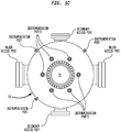
- FIGS 1B and 1C illustrate a configuration for reactor 30 of the present invention wherein access port(s) sized to allow entry is provided in the side wall of reactor 30 with catalyst support grid 38 spaced therebeneath allowing an overhead space suitably at least about 1.8 m (6 feet) of clearance between the fill level of the catalyst bed and the upper surface of the reactor chamber.
- Flow distribution is also important for avoiding channeling and hot spots in the catalyst bed.
- the preferred flow regime is fully turbulent and is enhanced by the presence of the inlet distributor. That is, an inlet distributor is advantageously provided to insure uniform flow distribution through the catalyst bed and prevent channeling and the potential creation of hot spots, which are likely to shorten the catalyst life.
- One preferred design for this inlet distributor device is in the form of baffles and rings which is mounted in the vapor space above the catalyst bed to promote even distribution of flow and to minimize inlet pressure losses.
- butene rich feed is vaporized in butene vaporizer 50 in which the heat required for vaporization is supplied by removal of heat from bottoms of quench tower 64 which, as will be discussed later, is heated by contact with the hot reaction product once a steady state operation has been achieve in the current process.
- the vaporized butene feed is mixed with steam, the steam being generated in two recycle condensate vaporizers 54 and 56.
- the steam generated in recycle condensate vaporizer 54 is produced by indirect heat exchange with butadiene enriched product stream leaving reactor feed superheater 48.
- the heat required to generate the steam in recycle condensate vaporizer 56 is preferably supplied by steam either from the plant grid or preferably from the thermal oxidizer or some other conveniently available source.
- the steam is completely vaporized in recycle condensate vaporizer 56 prior to being mixed with vaporized butene before passage through reactor feed superheater 48 in which the reactor feed is preheated by indirect heat exchange with the butadiene enriched product stream exiting reactor 30 with the resultant combined entry stream having a temperature of at least about 345°C (about 650°F), preferably in the range of from about 345°C to 400°C (from about 650°F to 750°F).
- the feed to reactor 30 is heated to the required temperature by indirect heat exchange with the exit stream which, as will be discussed later, is usually at a temperature in excess of 535°C (1000°F), more typically around 595°C (1100°F).
- the recovered heat passes through only a single tube wall in contrast to schemes in which an intermediate fluid is used.
- Preheated reactor feed leaving the reactor feed superheater 48 is mixed with compressed oxygen bearing gas, typically air, with the amount of air feed being carefully controlled so that approximately 0.5 to 0.6 moles of oxygen are supplied for each mole of hydrocarbon in the feed passed to the reactors.
- reaction feed stream is passed to refractory lined adiabatic reactor 30 illustrated in Figure 1 , where butene/steam/air feed inside reactor 30 passes first through: an inert flow distribution layer 32 then to an oxidative-dehydrogenation catalyst layer 34, having a depth of 83.8 cm (33 inches) or so; an aldehyde and acetylene removal (AAR) catalyst layer 36 and an inert support (alumina spheres) layer 38.
- AAR aldehyde and acetylene removal
- thermocouples 40 spaced along the height of oxidation-dehydrogenation layer 34 so that the location of the reaction zone therein may be determined.
- the amount of oxygen remaining in the product stream is monitored with oxygen analyzer 42 located near the bottom of layer 34 so that oxygen breakthrough into AAR layer 36 is avoided as discussed hereinafter in more detail.
- oxygen analyzer 42 located near the bottom of layer 34 so that oxygen breakthrough into AAR layer 36 is avoided as discussed hereinafter in more detail.
- a lower sample port 44 for a convergence analyzer in layer 36 so that composition may be monitored at the lower extreme of the reactor.
- Thermocouples 40 are also optionally disposed in layer 36 to monitor temperature in the AAR zone.
- any suitable temperature sensing device may be utilized, such as resistance temperature detectors, or noncontact sensors in a suitable reactor configuration.
- a target temperature for a reaction zone is pre-selected and maintained in the reaction zone.
- the reaction zone in layer 34 is initially disposed near the bottom of layer 34.
- the reaction zone or "active" layer of oxydehydrogenation catalyst layer 34 is characterized by a relatively sharp rise in temperature over a relatively short bed depth to the pre-selected target temperature.
- the reaction zone is characterized by a temperature rise of from 100°F to 300°F (55°C to 167°C) over a bed depth change of from 1 to 5 inches (2.5 cm to 13 cm) to the target temperature.
- the active layer is characterized by a temperature rise of from 150°F to 250°F (83°C to 139°C) over a bed depth of from 2 to 4 inches (5 cm to 10 cm). Below the reaction zone in bed 34, there is preferably no additional temperature rise if the system is controlled properly since oxygen is completely or nearly completely depleted in the reaction zone and is no longer present in the system.
- Suitable operating target temperatures for the oxydehydrogenation reaction zone are from 1000°F to 1200°F (540°C to 650°C).
- the inlet temperature to the reactor is raised and the active zone migrates upwardly in layer 34.
- the estimate of time to breakthrough is based on the temperature readings in the layers above the reaction zone (which are lower than the target temperature for the reaction zone) more so than on the temperatures at or below the reaction zone since the temperatures above the reaction zone are indicative of relatively fresh catalyst available to catalyze the reaction.
- thermocouple(s) indicate a fresh catalyst layer of 5 cm
- the oxidative dehydrogenation catalyst gives best performance for extended times.
- reactor feed superheater 48 ( Figure 2 ) which supplies a portion of the heat used to bring the feed to reactor 30 up to the requisite operating temperature and thence the reaction product exiting reactor feed superheater 48 passes through steam generator 54 wherein a portion of the sensible heat contained therein is used to vaporize and/or superheat the steam passing to reactor 30.
- butadiene enriched reaction product exiting from steam generator 54 passes to quench tower 64 ( Figure 3 ) entering at a height slightly above the maximum liquid level expected during normal operation.
- butadiene enriched product stream from reactor 30 is combined with other butadiene enriched product streams from the other reactors (not shown) prior to entering quench tower 64.
- bottom section 66 of quench tower 64 is equipped with valve trays while top section 70 is equipped with a corrugated metallic structured packing such as Koch Flexipac®, similar to that described in Lantz, et al., US Patent 6,874,769 , Structured Packing Plate and Element and Method of Fabricating Same or Rukovena, US Patent 4,740,334 .
- spray nozzles may be used for the entire tower. It is anticipated that in many cases, it will be possible to feed the mixture of vaporous and liquid reaction product effluent directly into quench tower 64 without any preliminary phase separation; but such preliminary phase separation can be easily accommodated, if expedient, by incorporation of a flash tank or similar phase separation device.
- quench condensate liquid phase collected at lower exit 67 of quench tower 64 composed primarily of condensed steam and quench water is fed back through the hot side of butene vaporizer 50 with cooled liquid return being passed back via quench condensate air cooler 76 and thence to quench tower circulating cooler 78 before being fed into quench tower 64 at a location well above the top of the packed section 70 of quench tower 64 but below demister pad 83.
- quench condensate air cooler 76 is equipped with modular tube banks, individually controlled fans, and variable pitch fan blades to facilitate temperature control in a variety of ambient conditions. In many cases, it will be possible to extract additional heat from Quench Tower 64 bottoms stream for uses elsewhere in the associated plant reducing size and cost of Quench Tower Coolers 76 and 78.
- Indirect inter-stage cooling is provided by compressor inter-stage coolers 88 and 89 with cooling to compressor inter-stage cooler 88 being supplied by a process stream leaving stripped water cooler 99 and the heated stream from the shell side of compressor inter- stage cooler 88 being fed to aldehyde stripper 98 ( Figure 4 ). Cooling to inter-stage cooler 89 is conveniently supplied by plant cooling tower water.
- Entrained liquid droplets coalesced on demister pad 83 are refluxed through quench tower 64 while compressed vaporous butadiene enriched product compressed to 1140 kPa abs. (about 150 psig) leaves the second stage of the gas compressor and it is passed to aldehyde scrubber 92 of which top portion 93 is preferably packed with structured packing which may be similar to Norton Intallox structured packing or those packings described above.
- a portion of the bottoms from aldehyde scrubber 92 is recycled through the structured packing via aldehyde scrubber bottoms cooler 95 while the remainder is passed to aldehyde stripper 98 via aldehyde scrubber bottoms separator 96 ( Figure 4 ) which receives liquid from the quench tower 64 bottoms via quench tower bottoms pump 65 as well as from gas compressor 84 second stage knock out drum.
- the water contents of the aldehyde scrubber bottoms separator 96 may be returned to quench tower 64 at a location below demister pad 83.
- Aldehyde stripper receives the water phase from the aldehyde scrubber bottoms after the oil phase has been skimmed out. This stream is pumped first to the shell side of stripped water cooler 99, from whence it reaches the shell side of compressor interstage cooler 88, which helps to increase its temperature via heat integration before being fed to aldehyde stripper 98, a portion of this overhead vapor from aldehyde stripper 98 going to aldehyde stripper overhead condenser 100 and thence being returned to aldehyde stripper 98 as reflux to maintain the vapor/liquid equilibrium in the column and drive overhead the aldehydes contained in the feed to this tower 98.
- the balance of the overhead vapor stream from aldehyde stripper 98 bypassing overhead condenser 100 is combined with other low value combustibles and directed to a thermal oxidizer (not shown) for production of superheated steam.
- Heavier hydrocarbons entrained in the condensed overhead stream from overhead condenser 100 are collected by bottoms coalescer and are also disposed of by treatment at a conventional oily water facility (not shown).
- Aldehyde stripper reboiler 102 uses steam, advantageously medium pressure steam, to vaporize a portion of aldehyde stripper bottoms from aldehyde stripper 98 and reintroduces the vapor below bottom tray of aldehyde stripper 98 while the remainder is pumped using adehyde stripper bottoms pump 105 to two locations: (1) back to the aldehyde scrubber 92 bottoms below the packing via two stripped water coolers (not shown), and (2) to the recycle condensate vaporizers, where it generates the vast bulk, if not all, of the steam used for the oxidative dehydrogenation reaction.
- steam advantageously medium pressure steam
- Reaction product from aldehyde scrubber 92 ( Figure 3 ) overhead is passed to the bottom of C4 absorber 110 ( Figure 5 ) containing numerous trays or other known devices for promoting gas liquid contact and equipped with at least one intercooler 111.
- Absorber oil (also sometimes referred to as lean oil) used in absorber 110 can suitably be paraffinic, or a mixture of paraffins and aromatics, although particularly superior results are obtained using oils which are richer in, or possibly even entirely, vinyl cyclohexene (butadiene dimer).
- Butadiene in the product stream is absorbed in absorber oil introduced at the top of C4 absorber 110, the bottoms from which is pumped to the top of degasser tower 116 through C4 absorber bottoms pump 113 and degasser feed cooler 115.
- Degasser tower 116 operates at lower pressure to facilitate the removal of residual gases, particularly carbon dioxide, nitrogen and hydrogen, which are passed through inter-stage cooler 88 of two-stage gas compressor 84 to the butadiene enriched product stream prior to passage through aldehyde scrubber 92.
- Degasser overhead gas from degasser 116 is recycled back to the second stage of compressor 84 and thence to scrubber 92 and absorber 110 whence it will ultimately find its way to thermal oxidizer 114.
- Degasser reboiler 122 maintains the temperature in the liquid phase of degasser tower 116 sufficiently high to allow residual gases to be flashed out passing to thermal oxidizer 114 as described above.
- the bottoms from degasser tower 116 largely comprising crude butadiene and miscellaneous C4's in absorber oil are passed to C4 stripper 124 through C4 stripper feed bottoms interchanger 127 where this bottoms stream is heated by passage of hot absorber oil from the bottoms of C4 stripper 124 through the tubes of C4 stripper feed/bottoms interchanger 127. Heated degasser bottoms are introduced into C4 stripper 124 at an intermediate height.
- Crude butadiene and C4's are stripped from heated absorber oil in C4 stripper 124, passing out as overhead to C4 stripper overhead condenser 130 while depleted absorber oil collected in the bottoms from C4 stripper 124 is reheated in C4 stripper reboiler 128; and the overhead vapor from C4 stripper 124 is condensed in C4 stripper overhead condenser 130 with a portion of the condensed liquid being accumulated in C4 stripper reflux drum 125 ,where residual water can be separated from the hydrocarbon phase and sent back to aldehyde stripper tower 98,while crude butadiene product is pumped through C4 stripper reflux pump 123 to further processing, while sufficient crude butadiene is being recirculated as reflux to ensure that sufficient separation is attained in C4 stripper 124.
- C4 stripper 124 comprise absorber oil having butadiene and other C4s stripped therefrom which is divided into three portions, one of which is recirculated to C4 stripper 124 through C4 stripper reboiler 128, a second portion being passed to absorber oil surge drum 142, ( Figure 6 ) the remaining portion being used as mentioned previously to heat butadiene/absorption oil mixture upon passage through C4 stripper feed/bottoms interchanger 127 where it, and oil being recycled from absorption oil surge drum 142, are passed to absorption oil air cooler 131 and absorption oil cooler 133 before being returned to C4 absorber 110 for reuse.
- absorber oil re-run tower 132 As absorber oil breaks down, forming heavier molecules, fresh oil make-up is introduced into the system while the balance is directed to a re-run column for heavies cleanup.
- absorber oil re-run tower 132 Upon sufficient accumulation of heavies in the absorption oil to justify, or necessitate, operation of absorber oil re-run tower 132, a portion of the oil being recirculated from absorption oil surge drum 142 is distilled to remove heavier components in absorber oil re-run tower bottoms with the overhead being pumped back to absorber oil recirculation loop. Occasionally the recovered oil could be pumped to storage tank 140 where the fresh absorber oil is stored.
- Tables 2 and 2A sets forth an energy balance for three possible plant configurations for 23,000 kg/hr (50,600 lb/hr) of butadiene production: one having no thermal oxidizer; one having a small thermal oxidizer sized primarily for the low value combustibles produced in the process of converting butene to butadiene; and one sized for both the low value combustibles produced in the process of converting butene to butadiene as well as those produced in the process of purifying crude butadiene to a saleable grade.
- All of the energy for Superheater 48, over 4400 kJ/kg (1900 BTU per pound) of butadiene, may be supplied by indirect heat transfer of sensible heat from the reactor effluent stream at high temperature, with the effluent product stream well above 370°C (700°F).
- all of the energy for vaporizer 54 may similarly be supplied by indirect heat transfer at a somewhat lower temperature of the effluent product stream.
- Heat recovery from the process stream is enhanced by extracting heat from the effluent stream when the stream is at a relatively high temperature for purposes of superheating the feed and then extracting heat from the reactor effluent at a relatively lower temperature for purposes of vaporizing feed.
- Energy for vaporizer 56 may be supplied from a plant steam grid which draws heat from thermal oxidation of volatile organic compounds generated in connection with the oxidative dehydration process as described herein.
- the inventive method may be practiced using a ferritic oxidative dehydrogenation catalyst which is substantially nitrate-free and may comprise: oxygen, a major proportion of iron; a minor proportion of zinc; and smaller amounts of manganese; phosphorus and a residue of a nitrate free calcium precursor.
- the process may be operated wherein the moles of oxygen in said reactor feed stream are controlled to so that at least 0.5 moles of oxygen are provided per mole of hydrocarbonaceous butene rich feed.
- the ferritic oxidative dehydrogenation catalyst bed generally has a depth of over 70 cm (27 inches) and the temperature sensing devices comprise thermocouples.
- the oxidative dehydrogenation catalysts may range from about 1 mm to about 30 mm in diameter such as from about 1 mm up to about 5 mm in diameter, optionally wherein the particles are pre-reduced or otherwise heat treated prior to loading to a degree sufficient to give them a crush strength necessary to be usable in a bed having a depth of from about 70 cm (27") up to about 150 cm (60"), the bulk density of the pre-reduced particles being no more than about 1120 kg/m 3 (70 lbs/ft 3 ).
- the bulk density of the pre-reduced particles may be between about 930 kg/m 3 and 1010 kg/m 3 (58 lbs/ft 3 and 63 lbs/ft 3 ).
- the oxidative dehydrogenation catalysts comprise: oxygen, a major proportion of iron; a minor proportion of zinc; and smaller amounts of manganese; phosphorus and a residue of a nitrate free calcium precursor.
- a method of manufacturing butadiene from a butene rich feed comprises the steps of:
- the oxidative dehydrogenation catalyst may comprise: oxygen, a major proportion of iron; a minor proportion of zinc; and smaller amounts of manganese; phosphorus and a residue of a nitrate free calcium precursor.
- a particularly preferred embodiment is directed to a method of manufacturing butadiene from a butene rich feed, comprising the steps of:
Description
- This international patent application is based on co-pending
US Provisional Patent Application Serial No. 61/617,535 - This international patent application is also based on co-pending
US Provisional Patent Application Serial No. 61/617,506 - Previously known processes for producing butadiene from butene rich hydrocarbonaceous feeds have used reactors whose shapes were largely governed by pressure drop considerations leading to reactors that would be considered shallow - the bed depth (linear dimension in the direction of flow) of all four layers of the bed often being limited to about a meter or less with the total height of the oxidative dehydrogenation catalyst being only about 55-60 cm (22-24 inches) or less. In particular, previous processes typically used natural gas to vaporize butene and heat a mixture of hydrocarbons, preferably butenes, oxygen and steam to a temperature in excess of 260°C (500°F), more commonly in excess of about 315°C (600 °F), and preferably over about 345°C (650° F) or, in some cases, even over 370°C (700° F). In a typical process, the reaction mixture includes butenes, oxygen in an amount of from about 0.4 moles to about 0.8 moles, more typically from slightly in excess of 0.5 moles up to about 0.65 moles of oxygen for each mole of butene in the butene rich hydrocarbonaceous feed, and superheated steam in amounts of from about 12:1 to about 16:1. The heated reaction mixture was passed over a multilayer bed comprising four layers: an inert flow distribution and catalyst retention layer which restricted channeling of the reaction mixture as it passed through the catalyst bed and also served to hold the lower layers in place against vorticity that might be present above the catalyst bed; the second layer comprising the bulk of the bed was a oxidation/dehydrogenation catalyst; while the third layer comprises an aldehyde and alkyne removal ("AAR") catalyst which converts alkynes and aldehydes in the product into compounds which are less detrimental to processes for polymerization of butadienes than alkynes and aldehydes. The lowest layer comprises an inert particulate support material. As mentioned typically, the total bed height would be limited to about a meter or less while the depth of the oxidative dehydrogenation layer was limited to less than about 56 cm (22 inches).
- While passing over the oxidation/dehydrogenation catalyst, the butenes were converted to butadiene accompanied by the liberation of a great deal of heat, resulting in temperatures in the neighborhood of 540°C or 595°C (1000° F or 1100 ° F). In the past, when the depth of the catalyst bed was shallow, breakthrough of oxygen to the AAR catalyst could be difficult to prevent even though care might typically be exercised to ensure that all of the oxygen present in the reaction mixture was consumed before reaching the AAR catalyst. Oxygen breakthrough can lead to both loss of the desired butadiene product and, even more seriously, damage to the AAR catalyst and/or reactor vessel. Consequently, in many cases, these considerations led to use of rather conservative cycle length and premature catalyst changeout, so that the effective catalyst life was shorter than necessary and percentage of time on-stream suffered.
- Subsequent to reaction, the reaction product mixture is cooled and butadiene separated by contact with absorber oil and subsequent fractionation. Typically, these processes produce crude butadiene at a purity ranging from about 50 to about 70%, more typically from about 55 to about 65%, which is passed onward in the plant for further processing using known technologies.
- References of interest are discussed below.
- Lewis; HYDROCARBON CONVERSION PROCESS USING NOVEL METALLO MANGANESE OXIDES; United States Patent No.
5,772,898; Jun. 30, 1998 ; relates to a hydrocarbon conversion process comprising contacting a hydrocarbon feed with a catalyst comprising a crystalline metallo manganese oxide composition having a three-dimensional framework structure, an intracrystalline pore system and an empirical chemical composition on an anhydrous basis expressed by the formula:
AyMn8-xMxO16
where A is a templating agent selected from alkali metals, alkaline earth metals and ammonium ion, "y" is the moles of A and varies from the group consisting of about 0.5 to about 2.0, M is a metal selected from the group consisting of chromium, zirconium, tin, platinum, rhodium, niobium, tantalum, vanadium, antimony, ruthenium, gallium and germanium, "x" is the moles of M and varies from about 0.01 to about 4.0 and is characterized in that manganese has a valence of +3, or +4, M has a valence of +3, +4 or +5 and the composition has the hollandite structure. - Sasaki et al.; IRON-ANTIMONY-CONTAINING METAL OXIDE CATALYST COMPOSITION AND PROCESS FOR PRODUCING THE SAME; United States Patent No.
5,139,988; Aug. 18, 1992 ; relates to a composition which contains as essential components: crystalline iron antimonate and at least one element selected from the group consisting of vanadium, molybdenum, and tungsten; is useful as a catalyst in the oxidation reaction of organic compounds. Also, a process for producing the composition is disclosed. - Dejaifve et al.; CATALYST FOR DEHYDROGENATING ORGANIC COMPOUNDS, A PROCESS FOR ITS PREPARATION AND ITS USE; United States Patent No.
4,975,407; Dec. 4,1990 ; relates to a catalyst derived from iron oxides providing agents and potassium oxide providing agents, characterized in that the molar ratio is in the range of from 1.5 to 60 and that a potassium ferrite K2Fe12O19 phase is present supported on an octahedral Fe3O4 matrix, showing crystalline epitaxy between the hexagonal structure of K2Fe12O19 and the (111) planes of the Fe3O4 spinel structure. - McFarland, ACETYLENE REMOVAL PROCESS; United States Patent No.
4,658,080; April 14, 1987 relates to a process for removing acetylene from organics streams, particularly those streams resulting from oxidative-dehydrogenation of C4-C8 hydrocarbons, using an acetylene reduction catalyst comprising ferrite and nickel oxide, an alkaline earth metal oxide, carbonate or hydroxide of magnesium, calcium, strontium or barium and an alkaline metal oxide carbonate or hydroxide based on lithium, potassium, sodium, or rubidium. Use of the catalyst is exemplified in a pipe reactor in which oxidative dehydrogenation is conducted on C4 - C8 hydrocarbons and the reaction product is immediately passed over a bed of the acetylene reduction catalyst in the same pipe reactor. See also McFarland; ACETYLENE REMOVAL PROCESS; United States Patent No.4,644,088; Feb. 17, 1987 and4,513,159; Apr. 23, 1985 . - Patel; PROCESS FOR REMOVING A-ACETYLENES FROM DIOLEFINS; United States Patent No.
4,266,086 ; relates to removal of alpha-acetylenes including vinyl acetylene and methyl acetylene from a feedstream containing butadiene and mixed monoolefins and alkanes contaminated with alpha-acetylenes in an amount up to about 1.0 percent by weight (% by wt) by contacting the liquid phase with a supported metal oxide catalyst(cupric oxide, silver oxide, or mixtures thereof) in the absence of hydrogen, at a temperature in the range from about 90°C (200° F.) to about 130°C (260° F). - In Besozzi et al.; PURIFICATION OF UNSATURATED COMPOUNDS; United States Patent No.
4,150,063; Apr. 17, 1979 ; gaseous streams containing unsaturated hydrocarbons and carbonyl compounds are contacted with a catalyst comprising at least one metal of group 8, 1b, 2b, 4b, 6b and at least one element from group 1a and 2a to destroy the carbonyl compounds without substantial loss of unsaturated hydrocarbons. - Miklas, METHOD OF ACTIVATING ZINC-FERRITE OXIDATIVE DEHYDROGENATION CATALYST; United States Patent No.
3,953,370; April 27, 1976 relates to use of steam at a temperature of from 370-700°C (700-1300°F) to activate a zinc ferrite oxidative hydrogenation catalyst for preparation of butadiene from C4-C8 hydrocarbons. - Tschopp; DIOLEFIN PRODUCTION AND PURIFICATION; United States Patent No.
3,943,185; Mar. 9, 1976 relates to a process for producing a stream of oxidatively dehydrogenated C4 hydrocarbons substantially free of oxygen and inert noncondensable gases removed comprising absorbing the C4 hydrocarbons in an absorber oil in a first zone; stripping oxygen and inert noncondensable gases from the mixture of adsorber oil and C4 hydrocarbons in a second zone which is operated under conditions of temperature and pressure to maintain an aqueous phase in the second zone; and withdrawing (1) a predominately aqueous phase from the second zone, (2) an overhead of predominately all of the oxygen and inert noncondensable gases and a bottoms of adsorber oil and C4 hydrocarbon substantially free of oxygen and inert noncondensable gases. - In Woerner et al; PURIFICATION OF UNSATURATED HYDROCARBONS BY EXTRACTIVE DISTILLATION WITH ADDITION OF LIQUID SOLVENT TO STRIPPER OVERHEAD; United States Patent No.
3,496,070; Feb. 17, 1970 , a hydrocarbon separation process is provided for the separation of a hydrocarbon mixture comprising 4 to 5 carbon atoms including unsaturated hydrocarbons which comprises: extractively distilling the hydrocarbon mixture with a selective solvent in an extractive distillation column whereby hydrocarbon is selectively extracted in the extractive distillation column to form a hydrocarbon-rich solvent fraction which is fed to a solvent stripping column with said solvent being taken off as a bottoms from said stripping column and a vaporous hydrocarbon fraction being taken as an overhead fraction from said stripping column; adding said selective solvent in liquid phase to the vaporous overhead from the solvent stripper to lower the pressure in the overhead condenser of the solvent stripper column and in the solvent stripper. It is said that the product of the process may alternatively be taken as an overhead from the solvent stripper instead of from the extractive distillation column. - Bajars; DEHYDROGENATION WITH MAGNESIUM FERRITE; United States Patent No.
3,284,536; Nov. 8, 1966 relates to dehydrogenating hydrocarbons in the vapor phase at elevated temperatures in the presence of oxygen and a catalyst containing magnesium ferrite. Hydrocarbons to be dehydrogenated according to the process are hydrocarbons of 4 to 7 carbon atoms, preferably aliphatic hydrocarbons selected from the group consisting of saturated hydrocarbons, monoolefins, diolefins and mixtures thereof of 4 to 5 or 6 carbon atoms having a straight chain of at least four carbon atoms, and cycloaliphatic hydrocarbons. Oxygen is present in the reaction zone in an amount within the range of 0.2 to 2.5 mols of oxygen per mol of hydrocarbon to be dehydrogenated. The temperature for the dehydrogenation reaction will be greater than 250°C, such as greater than about 300°C or 375°C, and the maximum temperature in the reactor may be about 650° C or 750° C or perhaps higher under certain circumstances. - Levin et al.; PROCESS FOR REMOVING ALDEHYDES AND/OR KETONES FROM AN OLEFINIC STREAM;
US Patent Application Publication 2004/0122275; Jun. 24, 2004 relates to removing an oxygenate impurity selected from aldehyde and/or ketone, from an olefinic product stream. The product stream is contacted with a metal oxide-containing catalyst in the presence of a C1 to C6 alcohol under conditions sufficient to convert the oxygenate impurity to an olefin and/or oxygenate of higher carbon number than the aldehyde and/or ketone. The metal oxide-containing catalyst typically comprises an oxide of at least one metal selected from the group consisting ofGroup 2 metals,Group 3 metals (including Lanthanide and Actinide series metals), and Group 4 metals. The catalyst may include two or more metals from the same group of metals. In one embodiment, the metal oxide containing catalyst comprises lanthanum oxide and magnesium oxide. In another, the catalyst comprises an oxide of a metal selected from the group consisting of Ti, Zr, and Hf. In yet another embodiment, the catalyst preferably comprises an oxide of a metal selected from the group consisting of Sc, Y, La, and Ce. - Van Egmond; Distillation PROCESS FOR REMOVAL OF METHYL ACETYLENE AND/OR PROPADIENE FROM AN OLEFIN STREAM;
US Patent Application Publication 2004/0122268; Jun. 24, 2004 relates to a process for producing a propylene product stream and/or a butylene product stream from an olefin stream by removing Methyl acetylene and/or propadiene (MAPD) from the propylene and/or butylene in a two-step fractionation process. - Welch, et al. in "BUTADIENE VIA OXIDATIVE DEHYDROGENATION", Hydrocarbon Processing Nov. 1978 pp. 131-136; discuss an oxidative dehydrogenation process, in which steam, air or oxygen, and normal butenes are heated and passed over an undisclosed autoregenerative heterogeneous catalyst at around 430°C (800°F) using steam as a heat sink to moderate the temperature rise in the adiabatic reactor system without using gas phase additives such as halogen and sulfur compounds. The process is said to consume essentially all of the oxygen in the feed usually leaving oxygen levels in the effluent below 0.3 percent. Acetylenes and oxygenated byproducts are major by products.
- Khabashesku, et al. "DEHYDROGENATION REACTIONS OF N-BUTENE TO BUTADIENE";
US Patent Application Publication 2011/0245568; Oct. 6, 2011 relates to a method for the dehydrogenation of n-butene over a dehydrogenation catalyst at a pressure of 1,000 mbar or less under reaction conditions to produce 1,3-butadiene at a yield level of at least 40 mol %. Stadig, "OXIDATIVE DEHYDROGENATION PROCESS";FR 2 093 792 A5; Jan. 28, 1972WO 02/22258 A2 US Patent No. 3,828,202 ; Aug. 6, 1074 relates to catalysts for dehydrogenation which can be prepared by coprecipitating the metal containing catalysts from a solution of metal ions in the presence of a low molecular weight polyhdric material. Utsunomiya Masaru et al., "METHOD FOR PRODUCING CONJUGATED DIENE",JP 2011-148765; Aug. 4, 2011 - Applicant has found that manufacturing of butadiene from a butene rich feed can be achieved by a method, comprising the steps of providing a butene rich hydrocarbonaceous feed, vaporizing and super heating said hydrocarbonaceous butene rich feed to a temperature of at least about 205°C (400° F), mixing said hydrocarbonaceous butene rich feed with superheated steam and an oxygen rich gas to form a reactor feed stream, the moles of oxygen in said reactor feed stream being controlled to fall in the range of at least about 0.4, more preferably at least about 0.5 moles of oxygen per mole of hydrocarbonaceous butene rich feed, oxidatively dehydrogenating said reactor feed stream over a catalyst comprising: a major proportion of iron oxide; a minor proportion of zinc oxide; and smaller amounts of manganese oxide; and phosphoric acid, along with a calcium oxide derived from a non-nitrogenous calcium precursor, preferably calcium acetate, and thereby forming a butadiene enriched product stream. In a typical embodiment the heated reaction feed mixture is passed over a multilayer bed comprising four layers: an inert flow distribution and catalyst retention layer, preferably comprising spheres of alpha-alumina, which restricts channeling of the reaction mixture as it passes through the catalyst bed and also serves to hold the lower layers in place against vorticity that might be present above the catalyst bed; the second layer comprising the bulk of the bed being a oxidation/dehydrogenation catalyst having itself a depth of more than 69 or 70 cm (27 inches); while the third layer comprises an aldehyde and alkyne removal ("AAR") catalyst which converts alkynes and aldehydes in the product into compounds which are less detrimental to processes for polymerization of butadienes than alkynes and aldehydes; and the lowest layer comprises an inert particulate support material. Preferably, inlet conditions, primarily temperature are controlled such that the oxidative dehydrogenation reactions initially occur in the lower part of the oxidative dehydrogenation catalyst bed, so that coking is avoided in those portions of the bed above the initial reaction zone and at least 3, preferably at least 5, more preferably at least about 8, up to from about 10 to 75 or more remotely readable thermocouples are inserted into the oxidation/dehydrogenation portion of the bed to monitor the temperature therein at a variety of depths as well as at locations spaced laterally, with respect to the direction of flow, therefrom, and the temperature profile is monitored to determine when the effective portion of the catalyst nearest the AAR catalyst is becoming deactivated. When this occurs, the inlet temperature is increased slightly so that location where the oxidation/dehydrogenation reactions are occurring may be walked up the catalyst bed slightly and a new layer of catalyst is brought into effective use. Subsequently, the reaction process is monitored to determine when the newly employed layer of catalyst is becoming deactivated and the inlet temperature is again increased to move the effective reaction layer higher in the bed. In this fashion, coking of the upper layers of catalyst can be controlled so that a layer of catalyst relatively unaffected by coking is always in use until the uppermost layer in the bed becomes severely enough deactivated that a catalyst change out is justified. Simultaneously through this process, oxygen content in the AAR catalyst as well as the lower layers of the oxidative dehydrogenation catalyst can be monitored as a backup to monitoring the temperature profile to further ensure that oxygen breakthrough into the AAR catalyst and the highly undesirable consequences thereof are avoided.
- The present invention relates to a method of manufacturing butadiene from a butene rich feed, comprising the steps of:
- providing a butene rich hydrocarbonaceous feed, vaporizing and super heating said hydrocarbonaceous butene rich feed to a temperature of at least 345°C (650° F), mixing said hydrocarbonaceous butene rich feed with superheated steam and an oxygen rich gas to form a reactor feed stream, wherein the moles of oxygen in said reactor feed stream being controlled to fall in the range of at least 0.5 moles of oxygen per mole of hydrocarbonaceous butene rich feed;
- providing a catalyst bed of granules of oxidative dehydrogenation catalyst, passing said reactor feed stream from an inlet through said catalyst bed and thereby forming a butadiene enriched product stream;
- said catalyst bed of oxidative dehydrogenation catalyst having associated therewith a plurality of temperature sensing devices adapted to measure temperature in the bed along a direction of flow;
- controlling inlet conditions to said reactor such that the oxidative dehydrogenation reactions initially occur in the layers of said oxidative dehydrogenation catalyst most distal to said inlet, including in a reaction zone, reacting said reactor feed stream over said catalyst and thereby forming a butadiene enriched product stream;
- monitoring the temperature along the length of the bed and from time to time, increasing the inlet temperature so that the reaction zone migrates toward said inlet to said oxidative dehydrogenation catalyst bed.
- The invention relates further to a method of manufacturing butadiene from a butene rich feed, comprising the steps of:
- providing a butene rich hydrocarbonaceous feed, vaporizing and super heating said hydrocarbonaceous butene rich feed to a temperature of at least 345°C (650° F), mixing said hydrocarbonaceous butene rich feed with superheated steam and an oxygen rich gas to form a reactor feed stream, wherein the moles of oxygen in said reactor feed stream being controlled to fall in the range of at least 0.5 moles of oxygen per mole of hydrocarbonaceous butene rich feed;
- providing a catalyst bed layer of granules of ferritic oxidative dehydrogenation catalyst, passing said reactor feed stream through said catalyst bed and thereby forming a butadiene enriched product stream;
- providing a bed layer of particles of AAR catalyst therebeneath,
- said catalyst bed of ferritic oxidative dehydrogenation catalyst having a plurality of temperature sensing devices embedded therein through its depth including at least one temperature sensing device spaced from 5 to 10 cm above the layer of AAR catalyst and another located from 15 to 25 cm above the layer of AAR catalyst;
- controlling inlet conditions to said reactor such that the oxidative dehydrogenation reactions initially occur in the lower most layers of said oxidative dehydrogenation catalyst, including in a reaction zone, reacting said reactor feed stream over said catalyst and thereby forming a butadiene enriched product stream;
- Suitable ferritic oxide catalysts for the present invention are usually somewhat friable or frangible so that, when conventional techniques are used to formulate and load the catalyst, there is considerable difficulty in ensuring that the catalyst bed does not become partially clogged by catalyst particle fragments. Such fragments can result from loading, relative motion between particles during operation or even the simple weight of particles above once the full depth of the bed has been reached. This issue may be addressed by both (i) pre-reducing the catalyst particles before they are loaded into the reactor to render them more wear resistant; as well as by (ii) loading the catalyst using a low impact loading technique such as sock or even loading the catalyst by hand as opposed to simple dumping. Ideally both the pre-reducing technique and low impact placement techniques will be used together to ensure that the pressure drop through the bed remains as low as possible.
- The invention is described in detail below with reference to numerous examples and the appended Figures wherein like numbers designate similar parts throughout and wherein:
-
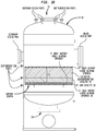
Figure 1A is a schematic sectional view of a reactor for use the practice of the present invention. -
Figures 1B and1C are more detailed schematics of a reactor shell illustrating the overhead space in the reactor above the catalyst support grid as well as the relative disposition of the access and instrumentation ports and the catalyst support grid. -
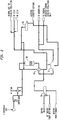
Figure 2 is a flow diagram of the reactor section of a crude butadiene battery illustrating the reactor and the pretreatment equipment for bringing the butene rich feed to the entry conditions required for operation of the reactor. -
Figure 3 is a flow diagram of a portion of a crude butadiene battery illustrating the Gas Compressing and Scrubbing equipment for initial processing of a butadiene enriched product stream produced by the reactor section ofFigure 2 . -
Figure 4 is a flow diagram of a portion of a crude butadiene battery illustrating the aldehyde stripper and associated equipment for processing of a butadiene enriched product stream after processing by the Gas Compressing and Scrubbing section ofFigure 3 . -
Figure 5 is a flow diagram of a portion of a crude butadiene battery illustrating the C4 absorption and stripping equipment for production of a crude stream of about 50% butadiene by processing of a butadiene enriched product stream received from the aldehyde stripper section ofFigure 4 . -
Figure 6 is a flow diagram of a portion of a crude butadiene battery illustrating portions of the system used for handling of lean oil after stripping of C4's therefrom. - The invention is described in detail below in connection with the Figures for purposes of illustration, only. The invention is defined in the appended claims. Terminology used throughout the specification and claims herein are given their ordinary meanings, for example, "indirect heat transfer" refers to heat transfer from one medium to another medium through a heat exchanger wall and pressures refer to gauge pressures unless otherwise indicated. When carrying out the inventive process, preferably heat is transferred through a single heat exchanger wall from a higher temperature stream to a lower temperature stream, such as from reactor effluent to reactor feed in a feed superheater as described hereinafter. Indirect heat transfer may be carried out in accordance with the invention using any suitable equipment such as tube and shell heat exchangers or plate and frame heat exchangers.
- Unless otherwise indicated, "butadiene" or "BD" refers to 1,3 butadiene or mixtures comprising 1,3 butadiene.
- The front end of butadiene production system of the present invention comprises multiple largely identical process trains, each process train having one
reactor 30 producing a butadiene enriched product stream from which useful heat is extracted by indirect heat exchange before entering quenchtower 64 at which point all process streams are combined. Only one train will be illustrated to avoid needless over-complication. - Referring to
Figures 1A-1C , reaction feed mixture comprising a butene rich hydrocarbonaceous gas, oxygen in a ratio of about 0.55 moles of oxygen per mole of hydrocarbon and steam in a ratio of about 15 moles of steam per mole of hydrocarbon enterreactor 30 through anupper inlet port 31 ofreactor 30 and flows downwardly before impacting uponlayer 32 of inert granules of alumina having an average particle size of about 3 mm to about 10 mm. Typically, these inert particles will be of a low surface area alumina such as perhaps alpha-alumina rather than some of the higher surface area forms usually loosely referred to as gamma alumina, although there are several intermediate forms of alumna exhibiting higher surface area than alpha-alumina. Spheres of alpha alumina having the following characteristics are quite suitable for both the uppermost and lowest layers in the catalyst bed:PROPERTIES MIN MAX Nominal Diameter, Inches 1/4 1/2 To Pass Opening, Inches 0.371 0.624 To Be Retained On Opening, Inches 0.263 0.525 Bulk Density, lb/ cu.ft 128 125 Nominal Diameter, cm 0.635 1.27 To Pass Opening, cm 0.942 1.585 To Be Retained On Opening, cm 0.668 1.334 Bulk Density, kg/m3 2050 2002 Upper layer 32 may be from about 50 mm to about 100 mm in depth, such as from about 65 to 85 mm in depth and in some cases from about 70 to 80 mm. Each layer in the catalyst bed, includingupper layer 32, is installed using a low-impact placement such as a sock loading technique to avoid damage to the catalyst layers therebelow while the depth ofupper layer 32 is limited to avoid crushing of the oxidative dehydrogenation catalyst therebeneath. When catalyst particles are sock loaded, it is important to avoid subjecting them to large forces such as those resulting from dropping the particles from a significant height. If the height of the sock above the bed is controlled so that particles are not allowed to fall through heights of more than about 91 cm (36 inches), there is little danger of significant damage to the particles, although drops from as high as 185 cm (70-75 inches) can sometimes be tolerated, particularly if the particles have been pre-reduced or otherwise heat treated to improve their toughness. Similarly, when the catalyst is placed in the hopper at the upper end of the sock, care is likewise observed so that the catalyst particles are not dropped from an excessive height. Hand loading can be used as well. - In other configurations, the sections of the
bed 35 which includeslayers oxidative dehydrogenation layer 34 underneath due to any turbulence or vorticity in the flow of reaction feed mixture approaching the catalyst bed. The oxidative dehydrogenation catalyst particles can be of any physical arrangement that will provide effective contact between the catalytically active species and the reactants, including dispersed on an inert support, but will typically be massive particles rather than being actives dispersed on a high surface area catalyst support. Preferably, the catalyst particles are from about 1 to about 25-30 mm in size, often taking the form of extrudates or spheres from about 1 mm up to about 5 mm in diameter. In particular, the catalyst particles preferably used in connection with the present invention should be slightly larger than commonly used in previous practice to limit the pressure drop through the catalyst bed as we prefer to use a catalyst bed which is deeper than commonly used previously. Higher pressure drop requires higher pressure in the system which reduces selectivity. We also prefer to use catalyst particles having two key differences from previous practice: (1) the particles are "pre-reduced" or otherwise heat treated prior to loading to give them the crush strength necessary to be usable in a bed having a depth of from about 50 cm to about 150 cm (from about 20" up to about 60"), suitably a depth of from about 65 cm to about 130 cm (from about 25" to about 50"), or from about 75 cm to about 100 cm (from about 30" to about 40"); while the bulk density of the calcined particles is no more than about 1100 kg/m3 (about 70 lbs/ft3), suitably between about 880 kg/m3 and 1050 kg/m3 (about 55 lbs/ft3 and 65 lbs/ft3) or between about 920 kg/m3 and 1010 kg/m3 (about 58 lbs/ft3 and 63 lbs/ft3) and (2) it is preferred to avoid the use of nitrates that are conventionally used as precursors for the calcium compounds often incorporated into these catalysts. Calcium acetate is a suitable precursor in this regard and has the advantage of reducing NOx emissions, while calcium chloride and calcium carbonate are also suitable. - Oxidative dehydrogenation catalyst particles having a composition as set forth in a companion application hereto, Low EMISSIONS OXIDATIVE DEHYDROGENATION PROCESS FOR PRODUCING BUTADIENE referenced above are disposed in layer or
bed 34 having a depth of from over 69 cm (27") up to about 152 cm (60"), preferably between about 71 cm (28") and 127 cm (50"), more preferably between about 76 cm (30") and 102 cm (40"), the butene rich hydrocarbonaceous feed is converted to a butadiene enriched reaction product stream which proceeds downstream of layer orbed 34 of oxidative dehydrogenation catalyst particles though layer orbed 36 of AAR catalyst - In
layer 36 of AAR catalyst particles, alkynes and aldehydes in butadiene enriched reaction product stream are converted to more innocuous species that are not so detrimental to use of butadiene in usual subsequent polymerization reactions. Preferably,AAR catalyst layer 36 is present in a depth of from about 40% to about 60% of the depth of the oxidative dehydrogenation catalyst, more preferably about 50 %. Alternatively, the depth can be from about 30 cm (12 inches) to about 51 cm (20 inches), more preferably from about 33 cm (13 inches) to about 48 cm (19 inches) and most preferably from about 36 cm (14 inches) to about 46 cm (18 inches). Beneathlayer 36 of AAR catalyst liesinert support layer 38 comprised of alumina spheres having a diameter of between about 1.0 cm (0.4 inches) and 2.54 cm (one inch), withinert support layer 38 being preferably from about 2.54 cm (1 inch) to about 20 cm (8 inches) in depth, preferably from about 5.08 cm (2 inches) to about 10 cm (4 inches) in depth, more preferably from about 6.4 cm to 8.9 cm (2.5 to 3.5 inches) in depth and even more preferably from about 6.99 cm to 7.62 cm (2.75 to 3 inches). In other cases, a layer of larger beads may be separated from the AAR catalyst by layer of smaller beads as depicted inFig. 1A . After exitinginert support layer 38, the butadiene enriched product stream exitsreactor 30 though thelower exit port 33 for subsequent recovery of the heat value contained therein and concentration of the butadiene content into a crude butadiene stream having a concentration of approximately 50 to 60% butadiene. - Typically, the catalytic process is initiated by raising the temperature of the catalyst bed to about 425°C (800°F); adding reactants until conversion is observed, then reducing the inlet temperatures to control the catalyst bed temperature. In most cases, natural gas is used to bring the streams up to temperature; then use of natural gas is sharply curtailed or cut off entirely once conversion is observed. In steady operation, as butene rich feed initially impacts upon the catalyst bed, the inlet conditions are carefully controlled so that most of the conversion of butenes into butadiene occurs in the last several cm of
layer 34 of oxidative dehydrogenation catalyst above the AAR catalyst, which initially registers as essentially a step change in temperature recorded by only the lowest of thosethermocouples 40 distributed throughoutlayer 34 of oxidative dehydrogenation catalyst, the thermocouples in the layer of oxidative dehydrogenation catalyst wherein the reaction is occurring. It is extremely important that the reaction is essentially complete before the reactants reach the AAR catalyst. This is primarily controlled by closely observing the temperature profile in the reactor to ensure that the reaction zone is located above the AAR catalyst and moves upwardly as lower layers of the oxidative dehydrogenation catalyst begin losing catalytic activity. As additional insurance, the location of the reaction zone can be verified by measuring the oxygen content just above the lowermost layer of oxidative dehydrogenation catalyst as well as in the AAR catalyst itself, the presence of any amount of oxygen being considered highly detrimental even though oxygen contents as high as 0.3% to 0.5% can be tolerated for short periods of time. As the reaction progresses, oxidative dehydrogenation catalyst in the lowermost portion oflayer 34 of oxidative dehydrogenation catalyst becomes deactivated which is indicated by decline in the registered temperature and may be reflected in selectivity or yield measurements as well. When the lower thermocouples in the array begin to register a decline in temperature such that there is any significant risk of oxygen breakthrough to the AAR catalyst, the inlet temperature is increased slightly to move the reaction zone upwardly in the oxidative dehydrogenation catalyst. In this way, coking of catalyst in layers of oxidative dehydrogenation catalyst above the layer in use is avoided. Throughout the process, the oxygen content, or more precisely the lack of significant oxygen content, in the AAR catalyst is carefully monitored to confirm that oxygen is not breaking through into the AAR catalyst layer. When the uppermost layer of oxidative dehydrogenation catalyst becomes deactivated to the extent that catalyst changeout is called for, the process is interrupted and a new catalyst bed is supplied. In many cases, a catalyst life of over 80 days up to about a year can be achieved, although it is not necessarily prudent to attempt to set records without a fair degree of certainty that oxygen breakthrough will be avoided. Typically, the inlet temperature must be increased progressively throughout the run so process economics suffer somewhat toward the end of the run, further discouraging attempts to set endurance records. In the absence of some upset, we expect a minimum of 180 days of catalyst life if the foregoing precautions are strictly observed. -
Figures 1B and1C illustrate a configuration forreactor 30 of the present invention wherein access port(s) sized to allow entry is provided in the side wall ofreactor 30 withcatalyst support grid 38 spaced therebeneath allowing an overhead space suitably at least about 1.8 m (6 feet) of clearance between the fill level of the catalyst bed and the upper surface of the reactor chamber. - Flow distribution is also important for avoiding channeling and hot spots in the catalyst bed. The preferred flow regime is fully turbulent and is enhanced by the presence of the inlet distributor. That is, an inlet distributor is advantageously provided to insure uniform flow distribution through the catalyst bed and prevent channeling and the potential creation of hot spots, which are likely to shorten the catalyst life. One preferred design for this inlet distributor device is in the form of baffles and rings which is mounted in the vapor space above the catalyst bed to promote even distribution of flow and to minimize inlet pressure losses.
- Referring to
Figure 2 , butene rich feed is vaporized inbutene vaporizer 50 in which the heat required for vaporization is supplied by removal of heat from bottoms of quenchtower 64 which, as will be discussed later, is heated by contact with the hot reaction product once a steady state operation has been achieve in the current process. After passing throughbutene vaporizer 50, the vaporized butene feed is mixed with steam, the steam being generated in tworecycle condensate vaporizers recycle condensate vaporizer 54 is produced by indirect heat exchange with butadiene enriched product stream leavingreactor feed superheater 48. The heat required to generate the steam inrecycle condensate vaporizer 56 is preferably supplied by steam either from the plant grid or preferably from the thermal oxidizer or some other conveniently available source. Preferably, the steam is completely vaporized inrecycle condensate vaporizer 56 prior to being mixed with vaporized butene before passage throughreactor feed superheater 48 in which the reactor feed is preheated by indirect heat exchange with the butadiene enriched productstream exiting reactor 30 with the resultant combined entry stream having a temperature of at least about 345°C (about 650°F), preferably in the range of from about 345°C to 400°C (from about 650°F to 750°F). Thus the feed toreactor 30 is heated to the required temperature by indirect heat exchange with the exit stream which, as will be discussed later, is usually at a temperature in excess of 535°C (1000°F), more typically around 595°C (1100°F). Significantly, the recovered heat passes through only a single tube wall in contrast to schemes in which an intermediate fluid is used. Preheated reactor feed leaving thereactor feed superheater 48 is mixed with compressed oxygen bearing gas, typically air, with the amount of air feed being carefully controlled so that approximately 0.5 to 0.6 moles of oxygen are supplied for each mole of hydrocarbon in the feed passed to the reactors. In some cases, it will be convenient to preheat the oxygen bearing gas to from about 205 to about 235°C (about 400 to about 450°F) using high pressure steam. After mixing, the reaction feed stream is passed to refractory linedadiabatic reactor 30 illustrated inFigure 1 , where butene/steam/air feed insidereactor 30 passes first through: an inertflow distribution layer 32 then to an oxidative-dehydrogenation catalyst layer 34, having a depth of 83.8 cm (33 inches) or so; an aldehyde and acetylene removal (AAR)catalyst layer 36 and an inert support (alumina spheres)layer 38. - The location of the intensely exothermic reaction occurring in each reactor is monitored through a number of remotely
readable thermocouples 40 spaced along the height of oxidation-dehydrogenation layer 34 so that the location of the reaction zone therein may be determined. The amount of oxygen remaining in the product stream is monitored withoxygen analyzer 42 located near the bottom oflayer 34 so that oxygen breakthrough intoAAR layer 36 is avoided as discussed hereinafter in more detail. Also provided is alower sample port 44 for a convergence analyzer inlayer 36 so that composition may be monitored at the lower extreme of the reactor.Thermocouples 40 are also optionally disposed inlayer 36 to monitor temperature in the AAR zone. Instead of thermocouples, any suitable temperature sensing device may be utilized, such as resistance temperature detectors, or noncontact sensors in a suitable reactor configuration. - In order to control the system, a target temperature for a reaction zone is pre-selected and maintained in the reaction zone. The reaction zone in
layer 34 is initially disposed near the bottom oflayer 34. The reaction zone or "active" layer ofoxydehydrogenation catalyst layer 34 is characterized by a relatively sharp rise in temperature over a relatively short bed depth to the pre-selected target temperature. Generally, the reaction zone is characterized by a temperature rise of from 100°F to 300°F (55°C to 167°C) over a bed depth change of from 1 to 5 inches (2.5 cm to 13 cm) to the target temperature. More typically, the active layer is characterized by a temperature rise of from 150°F to 250°F (83°C to 139°C) over a bed depth of from 2 to 4 inches (5 cm to 10 cm). Below the reaction zone inbed 34, there is preferably no additional temperature rise if the system is controlled properly since oxygen is completely or nearly completely depleted in the reaction zone and is no longer present in the system. - Suitable operating target temperatures for the oxydehydrogenation reaction zone are from 1000°F to 1200°F (540°C to 650°C). When the targeted temperature of the reaction zone begins to fall, the inlet temperature to the reactor is raised and the active zone migrates upwardly in
layer 34. One can estimate the time for oxygen breakthrough based on the rate of change of temperatures in the bed which is manifested in the rate of upward migration of the reaction zone and the remaining bed depth above the reaction zone. The estimate of time to breakthrough is based on the temperature readings in the layers above the reaction zone (which are lower than the target temperature for the reaction zone) more so than on the temperatures at or below the reaction zone since the temperatures above the reaction zone are indicative of relatively fresh catalyst available to catalyze the reaction. Thus, if the temporal temperature profile indicates that the reaction zone is migrating upwardly at a rate of 0.5 cm/day and the uppermost thermocouple(s) indicate a fresh catalyst layer of 5 cm, only 10 days of operation remain before oxygen breakthrough, provided that the oxydehydrogentation catalyst exhaustion rate remains relatively constant. - By controlling migration of the reaction zone in the manner described herein, the oxidative dehydrogenation catalyst gives best performance for extended times.
- As mentioned previously, the hot reaction product stream from
reactor 30 passes through reactor feed superheater 48 (Figure 2 ) which supplies a portion of the heat used to bring the feed toreactor 30 up to the requisite operating temperature and thence the reaction product exitingreactor feed superheater 48 passes throughsteam generator 54 wherein a portion of the sensible heat contained therein is used to vaporize and/or superheat the steam passing toreactor 30. - Subsequently, butadiene enriched reaction product exiting from
steam generator 54 passes to quench tower 64 (Figure 3 ) entering at a height slightly above the maximum liquid level expected during normal operation. As mentioned, in our preferred embodiment, butadiene enriched product stream fromreactor 30 is combined with other butadiene enriched product streams from the other reactors (not shown) prior to entering quenchtower 64. In one embodiment,bottom section 66 of quenchtower 64 is equipped with valve trays whiletop section 70 is equipped with a corrugated metallic structured packing such as Koch Flexipac®, similar to that described inLantz, et al., US Patent 6,874,769 , Structured Packing Plate and Element and Method of Fabricating Same orRukovena, US Patent 4,740,334 . Alternatively, spray nozzles may be used for the entire tower. It is anticipated that in many cases, it will be possible to feed the mixture of vaporous and liquid reaction product effluent directly into quenchtower 64 without any preliminary phase separation; but such preliminary phase separation can be easily accommodated, if expedient, by incorporation of a flash tank or similar phase separation device. The condensate liquid phase collected atlower exit 67 of quenchtower 64 composed primarily of condensed steam and quench water is fed back through the hot side ofbutene vaporizer 50 with cooled liquid return being passed back via quenchcondensate air cooler 76 and thence to quench tower circulating cooler 78 before being fed into quenchtower 64 at a location well above the top of the packedsection 70 of quenchtower 64 but belowdemister pad 83. Preferably quenchcondensate air cooler 76 is equipped with modular tube banks, individually controlled fans, and variable pitch fan blades to facilitate temperature control in a variety of ambient conditions. In many cases, it will be possible to extract additional heat fromQuench Tower 64 bottoms stream for uses elsewhere in the associated plant reducing size and cost ofQuench Tower Coolers - Crude butadiene vapor leaves
top section 70 of quench tower 64 (Figure 3 ) passing throughdemister pad 83, which is included primarily to protectgas compressor 84 from any entrained liquid droplets, and enters on the suction side of two-stagecentrifugal gas compressor 84. Indirect inter-stage cooling is provided by compressorinter-stage coolers water cooler 99 and the heated stream from the shell side of compressor inter-stage cooler 88 being fed to aldehyde stripper 98 (Figure 4 ). Cooling to inter-stage cooler 89 is conveniently supplied by plant cooling tower water. - Entrained liquid droplets coalesced on
demister pad 83 are refluxed through quenchtower 64 while compressed vaporous butadiene enriched product compressed to 1140 kPa abs. (about 150 psig) leaves the second stage of the gas compressor and it is passed toaldehyde scrubber 92 of whichtop portion 93 is preferably packed with structured packing which may be similar to Norton Intallox structured packing or those packings described above. A portion of the bottoms fromaldehyde scrubber 92 is recycled through the structured packing via aldehyde scrubber bottoms cooler 95 while the remainder is passed toaldehyde stripper 98 via aldehyde scrubber bottoms separator 96 (Figure 4 ) which receives liquid from the quenchtower 64 bottoms via quench tower bottoms pump 65 as well as fromgas compressor 84 second stage knock out drum. The water contents of the aldehyde scrubber bottoms separator 96 may be returned to quenchtower 64 at a location belowdemister pad 83. It is an important aspect of this invention that in those cases where substantial amounts of hydrocarbons lighter than C4 or other low value volatiles can be removed from various streams herein, those off gases are fed to a thermal oxidizer where they are combusted to produce steam which can be used to supply heat as needed for various portions of the overall process thereby greatly reducing need for natural gas combustion in steady operation and thereby also reducing concomitant generation of carbon monoxide and carbon dioxide. - Aldehyde stripper (
Figure 4 ) receives the water phase from the aldehyde scrubber bottoms after the oil phase has been skimmed out. This stream is pumped first to the shell side of strippedwater cooler 99, from whence it reaches the shell side of compressor interstage cooler 88, which helps to increase its temperature via heat integration before being fed toaldehyde stripper 98, a portion of this overhead vapor fromaldehyde stripper 98 going to aldehyde stripperoverhead condenser 100 and thence being returned toaldehyde stripper 98 as reflux to maintain the vapor/liquid equilibrium in the column and drive overhead the aldehydes contained in the feed to thistower 98. The balance of the overhead vapor stream fromaldehyde stripper 98 bypassingoverhead condenser 100 is combined with other low value combustibles and directed to a thermal oxidizer (not shown) for production of superheated steam. Heavier hydrocarbons entrained in the condensed overhead stream fromoverhead condenser 100 are collected by bottoms coalescer and are also disposed of by treatment at a conventional oily water facility (not shown).Aldehyde stripper reboiler 102 uses steam, advantageously medium pressure steam, to vaporize a portion of aldehyde stripper bottoms fromaldehyde stripper 98 and reintroduces the vapor below bottom tray ofaldehyde stripper 98 while the remainder is pumped using adehyde stripper bottoms pump 105 to two locations: (1) back to thealdehyde scrubber 92 bottoms below the packing via two stripped water coolers (not shown), and (2) to the recycle condensate vaporizers, where it generates the vast bulk, if not all, of the steam used for the oxidative dehydrogenation reaction. - Reaction product from aldehyde scrubber 92 (
Figure 3 ) overhead is passed to the bottom of C4 absorber 110 (Figure 5 ) containing numerous trays or other known devices for promoting gas liquid contact and equipped with at least oneintercooler 111. Absorber oil (also sometimes referred to as lean oil) used inabsorber 110 can suitably be paraffinic, or a mixture of paraffins and aromatics, although particularly superior results are obtained using oils which are richer in, or possibly even entirely, vinyl cyclohexene (butadiene dimer). Good commercial results have been obtained when the fresh absorber oil is primarily Espersol 250, an aromatic Naphtha product with a boiling range of 90°C to 150 °C (200°F to 300°F) having the composition shown in Table 1 (Celsius Boiling Points provided in Table 1A). Alternatively, a paraffinic naptha product with similar boiling points may be used.Table 1 Absorber Oil Composition Component Molecular Weight N.B. Point (°F) Specific Gravity Chroma. % Assumed Wt % Mole % Vol. % Benzene 78.11 176.2 0.8845 6 5 6.8 5 Cyclohexane 84.16 178 0.783 3 2 2.5 2.3 Methyl Cyclohexane 98.18 213.7 0.774 1 1 1.1 1.1 Toluene 92.13 231 0.872 12 13 15 13.2 2,2,4-Trimethyl Pentane 114.23 236.1 0.696 1 2 1.9 2.6 Vinyl Cyclohexane 108.18 262.1 0.8335 3 5 4.9 5.3 Ethyl Cyclohexane 112.22 269.2 0.788 1 1 0.9 1.1 M&P-Xylene 106.16 281 0.867 19 20 20.1 20.4 O-Xylene 106.16 291 0.885 17 18 18.1 18 Styrene 104.14 294 0.911 10 12 12.3 11.6 Propyl Benzene 120.19 318.6 0.862 1 2 1.8 2.1 Butyl Benzene 134.21 361.4 0.864 4 6 4.8 6.1 "Heavies" (Assume 2-M Naphthalene) 142.2 466 1.029 22 13 9.7 11.2 Table 1A Absorber Oil Composition (Celsius Boiling Points ) Component Molecular Weight N.B. Point (°C) Specific Gravity Chroma. % Assumed Wt % Mole % Vol. % Benzene 78.11 80.11 0.8845 6 5 6.8 5 Cyclohexane 84.16 81.1 0.783 3 2 2.5 2.3 Methyl Cyclohexane 98.18 100.9 0.774 1 1 1.1 1.1 Toluene 92.13 111 0.872 12 13 15 13.2 2,2,4-Trimethyl Pentane 114.23 113.4 0.696 1 2 1.9 2.6 Vinyl Cyclohexane 108.18 127.8 0.8335 3 5 4.9 5.3 Ethyl Cyclohexane 112.22 131.8 0.788 1 1 0.9 1.1 M&P-Xylene 106.16 138 0.867 19 20 20.1 20.4 O-Xylene 106.16 144 0.885 17 18 18.1 18 Styrene 104.14 146 0.911 10 12 12.3 11.6 Propyl Benzene 120.19 159.2 0.862 1 2 1.8 2.1 Butyl Benzene 134.21 183 0.864 4 6 4.8 6.1 "Heavies" (Assume 2-M Naphthalene) 142.2 241 1.029 22 13 9.7 11.2 - Butadiene in the product stream is absorbed in absorber oil introduced at the top of
C4 absorber 110, the bottoms from which is pumped to the top ofdegasser tower 116 through C4 absorber bottoms pump 113 anddegasser feed cooler 115.Degasser tower 116 operates at lower pressure to facilitate the removal of residual gases, particularly carbon dioxide, nitrogen and hydrogen, which are passed through inter-stage cooler 88 of two-stage gas compressor 84 to the butadiene enriched product stream prior to passage throughaldehyde scrubber 92. Degasser overhead gas fromdegasser 116 is recycled back to the second stage ofcompressor 84 and thence to scrubber 92 andabsorber 110 whence it will ultimately find its way tothermal oxidizer 114.Degasser reboiler 122 maintains the temperature in the liquid phase ofdegasser tower 116 sufficiently high to allow residual gases to be flashed out passing tothermal oxidizer 114 as described above. The bottoms fromdegasser tower 116 largely comprising crude butadiene and miscellaneous C4's in absorber oil are passed toC4 stripper 124 through C4 stripper feed bottoms interchanger 127 where this bottoms stream is heated by passage of hot absorber oil from the bottoms ofC4 stripper 124 through the tubes of C4 stripper feed/bottoms interchanger 127. Heated degasser bottoms are introduced intoC4 stripper 124 at an intermediate height. Crude butadiene and C4's are stripped from heated absorber oil inC4 stripper 124, passing out as overhead to C4 stripperoverhead condenser 130 while depleted absorber oil collected in the bottoms fromC4 stripper 124 is reheated inC4 stripper reboiler 128; and the overhead vapor fromC4 stripper 124 is condensed in C4 stripperoverhead condenser 130 with a portion of the condensed liquid being accumulated in C4stripper reflux drum 125,where residual water can be separated from the hydrocarbon phase and sent back toaldehyde stripper tower 98,while crude butadiene product is pumped through C4stripper reflux pump 123 to further processing, while sufficient crude butadiene is being recirculated as reflux to ensure that sufficient separation is attained inC4 stripper 124. - Bottoms leaving
C4 stripper 124 comprise absorber oil having butadiene and other C4s stripped therefrom which is divided into three portions, one of which is recirculated toC4 stripper 124 throughC4 stripper reboiler 128, a second portion being passed to absorberoil surge drum 142, (Figure 6 ) the remaining portion being used as mentioned previously to heat butadiene/absorption oil mixture upon passage through C4 stripper feed/bottoms interchanger 127 where it, and oil being recycled from absorptionoil surge drum 142, are passed to absorptionoil air cooler 131 andabsorption oil cooler 133 before being returned toC4 absorber 110 for reuse. As absorber oil breaks down, forming heavier molecules, fresh oil make-up is introduced into the system while the balance is directed to a re-run column for heavies cleanup. Upon sufficient accumulation of heavies in the absorption oil to justify, or necessitate, operation of absorberoil re-run tower 132, a portion of the oil being recirculated from absorptionoil surge drum 142 is distilled to remove heavier components in absorber oil re-run tower bottoms with the overhead being pumped back to absorber oil recirculation loop. Occasionally the recovered oil could be pumped tostorage tank 140 where the fresh absorber oil is stored. - Tables 2 and 2A sets forth an energy balance for three possible plant configurations for 23,000 kg/hr (50,600 lb/hr) of butadiene production: one having no thermal oxidizer; one having a small thermal oxidizer sized primarily for the low value combustibles produced in the process of converting butene to butadiene; and one sized for both the low value combustibles produced in the process of converting butene to butadiene as well as those produced in the process of purifying crude butadiene to a saleable grade. It can be appreciated that the energy requirement for vaporizing and superheating the various streams fed to the reactor during steady operation of the process for converting butenes to butadiene is surprisingly small when sensible heat in the reaction product stream is combined with the energy resulting from thermal oxidation of low value combustibles from both butadiene production and purification.
Table 2 Low Emissions/Heat Integration for Oxidative Dehydrogenation of Butene BD Production: 50,600 LB/HR Total Energy† Required: 432,112,000 BTU/HR Energy provided by Sensible Heat in Butadiene Enriched Product Stream (BTU/HR) Butene Vaporizer 50 14,558,000 Superheater 48 (Butene) - Superheater 48 (Steam) 95,783,000 Condensate Vaporizer 54 111,613,000 SubTotal† 221,954,000 Additional Energy Required to Vaporize Steam for Reactor Feed (BTU/HR)* Condensate Vaporizer 56 210,159, 000 * Energy calculated based on 150# superheated steam @ 810°F generated by combination of thermal oxidation of by-products from butene and butadiene production as supplemented by combustion of natural gas at 21,000 BTU/LB as fuel for steam boiler to produce 1112 BTU/LB of Steam during first phase of steady operation Thermal Oxidizer Size: Energy Contribution from Combustion of By-Products (Supplied via Steam) % Energy from Process Sources % Energy from Fossil fuel Lbs. of NG required for each Ib of Butadiene Produced % Energy for Vaporizing Recycle Condensate and Superheating Feed from Thermal Oxidizer % Energy for Vaporizing Recycle Condensate and Superheating Feed from Reactor Effluent none 0 51 48 0.20 -- 51 offgases from Crude BD production only 150,000 #/hr 150# Steam 61 39 0.16 10 51 Offgases from production and purification of Crude BD 250,000 #/hr 150# Steam 91 9 0.04 40 51 † Totals do not agree perfectly due to rounding. Table 2A (Metric Units) Low Emissions/Heat Integration for Oxidative Dehydrogenation of Butene BD Production: 23,000 kg/HR Total Energy† Required: 455,597,000 kJ/HR Energy provided by Sensible Heat in Butadiene Enriched Product Stream (kJ/HR) Butene Vaporizer 50 15,349,000 Superheater 48 (Butene) -- Superheater 48 (Steam) 100,988,000 Condensate Vaporizer 54 117,679,100 SubTotal† 234,017,000 Additional Energy Required to Vaporize Steam for Reactor Feed (kJ/HR)* Condensate Vaporizer 56 221,581,000 * Energy calculated based on 68.0 kg superheated steam @ 432°C generated by combination of thermal oxidation of by-products from butene and butadiene production as supplemented by combustion of natural gas at 48,813 kJ/kg as fuel for steam boiler to produce 2585 kJ/kg of Steam during first phase of steady operation Thermal Oxidizer Size: Energy Contribution from Combustion of By-Products (Supplied via Steam) % Energy from Process Sources % Energy from Fossil fuel kg. of NG required for each kg of Butadiene Produced % Energy for Vaporizing Recycle Condensate and Superheating Feed from Thermal Oxidizer % Energy for Vaporizing Recycle Condensate and Superheating Feed from Reactor Effluent none 0 51 48 0.20 -- 51 offgases from Crude BD production only 68,000 kg/hr 1 MPa Steam 61 39 0.16 10 51 Offgases from production and purification of Crude BD 113,000 kg/hr 1 MPa Steam 91 9 0.04 40 51 - Energy requirements for the reaction section can also be expressed in kJ/kg (BTU/LB) BD (butadiene) produced as set forth in Tables 3 and 3A below.
Table 3 - Reaction Section Energy Utilization Total Energy required*: 8540 BTU/LB BD Energy for Superheater 481890 BTU/LB BD Energy for Vaporizer 50288 BTU/LB BD Energy for Vaporizer 542200 BTU/LB BD Energy for Vaporizer 564150 BTU/LB BD *Approx. values Table 3A, Metric Units Total Energy required*: 19,900 kJ/kg BD Energy for Superheater 484,400 kJ/kg BD Energy for Vaporizer 50670 kJ/kg BD Energy for Vaporizer 545,130 kJ/kg BD Energy for Vaporizer 569,650 kJ/kg BD *Approx. values - All of the energy for
Superheater 48, over 4400 kJ/kg (1900 BTU per pound) of butadiene, may be supplied by indirect heat transfer of sensible heat from the reactor effluent stream at high temperature, with the effluent product stream well above 370°C (700°F). Likewise, all of the energy forvaporizer 54 may similarly be supplied by indirect heat transfer at a somewhat lower temperature of the effluent product stream. Heat recovery from the process stream is enhanced by extracting heat from the effluent stream when the stream is at a relatively high temperature for purposes of superheating the feed and then extracting heat from the reactor effluent at a relatively lower temperature for purposes of vaporizing feed. Energy forvaporizer 56 may be supplied from a plant steam grid which draws heat from thermal oxidation of volatile organic compounds generated in connection with the oxidative dehydration process as described herein. - In its various aspects, the inventive method may be practiced using a ferritic oxidative dehydrogenation catalyst which is substantially nitrate-free and may comprise: oxygen, a major proportion of iron; a minor proportion of zinc; and smaller amounts of manganese; phosphorus and a residue of a nitrate free calcium precursor. So also, the process may be operated wherein the moles of oxygen in said reactor feed stream are controlled to so that at least 0.5 moles of oxygen are provided per mole of hydrocarbonaceous butene rich feed. The ferritic oxidative dehydrogenation catalyst bed generally has a depth of over 70 cm (27 inches) and the temperature sensing devices comprise thermocouples.
- Further, there is disclosed a method of manufacturing butadiene from a butene rich feed, comprising the steps of:
- providing a catalyst bed layer of granules of ferritic oxidative dehydrogenation catalyst and a bed of particles of AAR catalyst therebeneath, said catalyst bed of ferritic oxidative dehydrogenation catalyst having a plurality of thermocouples embedded therein through its depth including at least one thermocouple spaced from about 5 to about 10 cm above the layer of AAR catalyst and another located from about 15 to about 25 cm above the layer of AAR catalyst;
- providing a butene rich hydrocarbonaceous feed, vaporizing and super heating said hydrocarbonaceous butene rich feed to a temperature of at least about 345°C (650° F), mixing said hydrocarbonaceous butene rich feed with superheated steam and an oxygen rich gas to form a reactor feed stream;
- controlling inlet conditions to said reactor such that the oxidative dehydrogenation reactions occur in the lower most layers of said oxidative dehydrogenation catalyst, including in a reaction zone, reacting said reactor feed stream over said catalyst and thereby forming a butadiene enriched product stream;
- monitoring the temperature throughout the bed and from time to time in response to a drop in the temperature in the reaction zone, calculating from time to time when oxygen breakthrough should occur based upon the measured temperatures and based upon the observed rate of change in the temperatures indicated by the plurality of thermocouples;
- increasing the inlet temperature when the active layer of oxidative dehydrogenation catalyst begins to become deactivated so that the reaction zone moves upwardly in the oxidative dehydrogenation bed, calculating from time to time when oxygen breakthrough should occur based upon the measured temperatures and based upon the observed rate of change in the temperatures indicated by the plurality of thermocouples and discontinuing the feed of butene rich hydrocarbonaceous feed before the predicted time for oxygen breakthrough, wherein during at least some period of time, the predicted time calculated for oxygen breakthrough is based upon the temperatures indicated by at least two thermocouples nearer the uppermost oxidative dehydrogenation catalyst layer more so than the temperatures indicated by thermocouples more distantly spaced from the uppermost oxidative dehydrogenation catalyst layer; and
- discontinuing the feed of butene rich hydrocarbonaceous feed prior to the anticipated time of oxygen breakthrough as indicated by the temperature profile in the oxidative dehydrogenation catalyst bed.
- The oxidative dehydrogenation catalysts may range from about 1 mm to about 30 mm in diameter such as from about 1 mm up to about 5 mm in diameter, optionally wherein the particles are pre-reduced or otherwise heat treated prior to loading to a degree sufficient to give them a crush strength necessary to be usable in a bed having a depth of from about 70 cm (27") up to about 150 cm (60"), the bulk density of the pre-reduced particles being no more than about 1120 kg/m3 (70 lbs/ft3). The bulk density of the pre-reduced particles may be between about 930 kg/m3 and 1010 kg/m3 (58 lbs/ft3 and 63 lbs/ft3). Suitably, wherein the oxidative dehydrogenation catalysts comprise: oxygen, a major proportion of iron; a minor proportion of zinc; and smaller amounts of manganese; phosphorus and a residue of a nitrate free calcium precursor.
- In another aspect, a method of manufacturing butadiene from a butene rich feed is described, comprises the steps of:
- providing a catalyst bed layer of granules of ferritic oxidative dehydrogenation catalyst and a bed of particles of AAR catalyst therebeneath by positioning said catalyst particles in said bed by positively positioning, without dumping, said particles, said catalyst bed of ferritic oxidative dehydrogenation catalyst having a plurality of thermocouples embedded therein through its depth including at least one thermocouple spaced from about 5 to about 10 cm above the layer of AAR catalyst and another located from about 15 to about 25 cm above the layer of AAR catalyst;
- providing a butene rich hydrocarbonaceous feed, vaporizing and superheating said hydrocarbonaceous butene rich feed to a temperature of at least about 345°C (650° F), mixing said hydrocarbonaceous butene rich feed with superheated steam and an oxygen rich gas to form a reactor feed stream;
- controlling inlet conditions to said reactor such that the oxidative dehydrogenation reactions occur in the lower most layers of said oxidative dehydrogenation catalyst, including in a reaction zone, reacting said reactor feed stream over said catalyst and thereby forming a butadiene enriched product stream;
- monitoring the temperature throughout the bed and from time to time in response to a drop in the temperature in the reaction zone, calculating from time to time when oxygen breakthrough should occur based upon the measured temperatures based upon the observed rate of change in the temperatures indicated by the plurality of thermocouples;
- increasing the inlet temperature when the active layer of oxidative dehydrogenation catalyst begins to become deactivated so that the reaction zone moves upwardly in the oxidative dehydrogenation bed, calculating from time to time when oxygen breakthrough should occur based upon the measured temperatures and based upon the observed rate of change in the temperatures indicated by the plurality of thermocouples and discontinuing the feed of butene rich hydrocarbonaceous feed before the predicted time for oxygen breakthrough, wherein during at least some period of time, the predicted time calculated for oxygen breakthrough is based upon the temperatures indicated by at least two thermocouples nearer the uppermost oxidative dehydrogenation catalyst layer more so than the temperatures indicated by thermocouples more distantly spaced from the uppermost oxidative dehydrogenation catalyst layer; and
- discontinuing the feed of butene rich hydrocarbonaceous feed prior to the anticipated time of oxygen breakthrough as indicated by the temperature profile in the oxidative dehydrogenation catalyst bed.
- In still yet another aspect there is provided a method of manufacturing butadiene from a butene rich feed, comprising the steps of:
- providing a catalyst bed of granules of ferritic oxidative dehydrogenation catalyst and a bed of particles of AAR catalyst therebeneath, said catalyst bed of ferritic oxidative dehydrogenation catalyst having a plurality of at least about 5 thermocouples embedded therein through its depth including at least one thermocouple spaced from about 5 to about 10 cm above the layer of AAR catalyst and another located from about 15 to about 25 cm above the layer of AAR catalyst,
- providing a butene rich hydrocarbonaceous feed, vaporizing and superheating said hydrocarbonaceous butene rich feed to a temperature of at least about 345°C (650° F), mixing said hydrocarbonaceous butene rich feed with superheated steam and an oxygen rich gas to form a reactor feed stream;
- controlling inlet conditions to said reactor such that the oxidative dehydrogenation reactions occur in the lower most layers of said oxidative dehydrogenation catalyst, including in a reaction zone, reacting said reactor feed stream over said catalyst and thereby forming a butadiene enriched product stream;
- monitoring the temperature throughout the bed and from time to time in response to a drop in the temperature in the reaction zone, active layer, calculating from time to time when oxygen breakthrough should occur based upon the measured temperatures based upon the observed rate of change in the temperatures indicated by the plurality of thermocouples,
- increasing the inlet temperature when the active layer of oxidative dehydrogenation catalyst begins to become deactivated so that the reaction zone moves upwardly in the oxidative dehydrogenation bed, and discontinuing the feed of butene rich hydrocarbonaceous feed before the predicted time for oxygen breakthrough.
- In any embodiment, the oxidative dehydrogenation catalyst may comprise: oxygen, a major proportion of iron; a minor proportion of zinc; and smaller amounts of manganese; phosphorus and a residue of a nitrate free calcium precursor.
- A particularly preferred embodiment is directed to a method of manufacturing butadiene from a butene rich feed, comprising the steps of:
- providing a butene rich hydrocarbonaceous feed, vaporizing and super heating said hydrocarbonaceous butene rich feed to a temperature of at least about 650° F, mixing said hydrocarbonaceous butene rich feed with superheated steam and an oxygen rich gas to form a reactor feed stream, the moles of oxygen in said reactor feed stream being controlled to fall in the range of at least about 0.5 moles of oxygen per mole of hydrocarbonaceous butene rich feed;
- providing a catalyst bed having a depth of over about 70 cm (27 inches) of granules of substantially nitrate-free ferritic oxidative dehydrogenation catalyst, passing said reactor feed stream through said catalyst bed and thereby forming a butadiene enriched product stream;
- providing a bed of particles of AAR catalyst therebeneath, said catalyst beds having a plurality of thermocouples embedded therein through the depth of each bed including at least one thermocouple spaced from about 5 to about 10 cm above the layer of AAR catalyst and another located from about 15 to about 25 cm above the layer of AAR catalyst,
- controlling inlet conditions to said reactor such that the oxidative dehydrogenation reactions initially occur in the lower most layers of said oxidative dehydrogenation catalyst, including in a reaction zone, reacting said reactor feed stream over said catalyst and thereby forming a butadiene enriched product stream;
- monitoring the temperature throughout the bed and from time to time in response to a drop in the temperature in the reaction zone, increasing the inlet temperature when the active layer of oxidative dehydrogenation catalyst begins to become deactivated so that the reaction zone moves upwardly in the oxidative dehydrogenation bed, and discontinuing the feed of butene rich hydrocarbonaceous feed after the temperature indicated by the thermocouple located in the uppermost portions of the oxidative dehydrogenation catalyst bed begins to drop.
Claims (15)
- A method of manufacturing butadiene from a butene rich feed, comprising the steps of:providing a butene rich hydrocarbonaceous feed, vaporizing and super heating said hydrocarbonaceous butene rich feed to a temperature of at least 345°C (650° F), mixing said hydrocarbonaceous butene rich feed with superheated steam and an oxygen rich gas to form a reactor feed stream;providing a catalyst bed of granules of oxidative dehydrogenation catalyst, passing said reactor feed stream from an inlet through said catalyst bed and thereby forming a butadiene enriched product stream;said catalyst bed of oxidative dehydrogenation catalyst having associated therewith a plurality of temperature sensing devices adapted to measure temperature in the bed along a direction of flow;controlling inlet conditions to said reactor such that the oxidative dehydrogenation reactions initially occur in the layers of said oxidative dehydrogenation catalyst most distal to said inlet, including in a reaction zone, reacting said reactor feed stream over said catalyst and thereby forming a butadiene enriched product stream;monitoring the temperature along the length of the bed and from time to time, increasing the inlet temperature so that the reaction zone migrates toward said inlet to said oxidative dehydrogenation catalyst bed.
- The method of manufacturing butadiene from a butene rich feed of claim 1, further comprising passing the butadiene enriched product stream through a bed of AAR catalyst effective to remove acetylenic impurities therefrom.
- The method of manufacturing butadiene from a butene rich feed of claim 1, wherein the oxidative dehydrogenation catalyst granules range from 1 mm to 30 mm in diameter.
- The method of manufacturing butadiene from a butene rich feed of claim 1, wherein the oxidative dehydrogenation catalyst granules range from 1 mm up to 5 mm in diameter.
- The method of manufacturing butadiene from a butene rich feed of claim 1, wherein the oxidative dehydrogenation catalyst is a ferritic oxidative dehydrogenation catalyst.
- The method of manufacturing butadiene from a butene rich feed of claim 1, wherein the ferritic oxidative dehydrogenation catalyst is substantially nitrate-free.
- The method of manufacturing butadiene from a butene rich feed of claim 6, wherein the oxidative dehydrogenation catalysts comprise: oxygen, a major proportion of iron; a minor proportion of zinc; and smaller amounts of manganese; phosphorus and a residue of a nitrate free calcium precursor.
- The method of manufacturing butadiene from a butene rich feed of claim 1, wherein the moles of oxygen in said reactor feed stream are controlled to so that at least 0.5 moles of oxygen are provided per mole of hydrocarbonaceous butene rich feed.
- The method of manufacturing butadiene from a butene rich feed of claim 1, wherein the ferritic oxidative dehydrogenation catalyst bed has a depth of over 70 cm (27 inches).
- The method of manufacturing butadiene from a butene rich feed of claim 1, wherein the temperature sensing devices comprise thermocouples.
- A method of manufacturing butadiene from a butene rich feed, comprising the steps of:providing a butene rich hydrocarbonaceous feed, vaporizing and super heating said hydrocarbonaceous butene rich feed to a temperature of at least 345°C (650° F), mixing said hydrocarbonaceous butene rich feed with superheated steam and an oxygen rich gas to form a reactor feed stream;providing a catalyst bed layer of granules of ferritic oxidative dehydrogenation catalyst, passing said reactor feed stream through said catalyst bed and thereby forming a butadiene enriched product stream;providing a bed layer of particles of AAR catalyst therebeneath,said catalyst bed of ferritic oxidative dehydrogenation catalyst having a plurality of temperature sensing devices embedded therein through its depth including at least one temperature sensing device spaced from 5 to 10 cm above the layer of AAR catalyst and another located from 15 to 25 cm above the layer of AAR catalyst;controlling inlet conditions to said reactor such that the oxidative dehydrogenation reactions initially occur in the lower most layers of said oxidative dehydrogenation catalyst, including in a reaction zone, reacting said reactor feed stream over said catalyst and thereby forming a butadiene enriched product stream;monitoring the temperature throughout the bed and from time to time in response to a drop in the temperature in the reaction zone, increasing the
inlet temperature when the active layer of oxidative dehydrogenation catalyst in said reaction zone begins to become deactivated so that the reaction zone moves upwardly in the oxidative dehydrogenation bed, and discontinuing the feed of butene rich hydrocarbonaceous feed after the temperature indicated by the temperature sensing device located in the uppermost portions of the oxidative dehydrogenation catalyst bed begins to drop. - The method of manufacturing butadiene from a butene rich feed of claim 11, wherein the oxidative dehydrogenation catalyst granules range from 1 mm to 30 mm in diameter.
- The method of manufacturing butadiene from a butene rich feed of claim 11, wherein the oxidative dehydrogenation catalyst granules range from 1 mm up to 5 mm in diameter.
- The method of manufacturing butadiene from a butene rich feed of claim 11, wherein the granules are pre-reduced or otherwise heat treated prior to loading to a degree sufficient to give them a crush strength necessary to be usable in a bed having a depth of from 60 cm (27") up to 150 cm (60"), the bulk density of the pre-reduccd particles being no more than 1121 kg/m3 (70 lbs/ft3).
- The method of manufacturing butadiene from a butene rich feed of claim 14, the bulk density of the pre-reduced granules being between 930 kg/m3 and 1010 kg/m3 (58 lbs/ft3 and 63 lbs/ft3).
Applications Claiming Priority (3)
| Application Number | Priority Date | Filing Date | Title |
|---|---|---|---|
| US201261617506P | 2012-03-29 | 2012-03-29 | |
| US201261617535P | 2012-03-29 | 2012-03-29 | |
| PCT/US2013/034215 WO2013148913A1 (en) | 2012-03-29 | 2013-03-28 | Improved controllability oxidative dehydrogenation process for producing butadiene |
Publications (3)
| Publication Number | Publication Date |
|---|---|
| EP2831021A1 EP2831021A1 (en) | 2015-02-04 |
| EP2831021A4 EP2831021A4 (en) | 2015-11-18 |
| EP2831021B1 true EP2831021B1 (en) | 2019-11-27 |
Family
ID=49261226
Family Applications (2)
| Application Number | Title | Priority Date | Filing Date |
|---|---|---|---|
| EP13769936.9A Active EP2831022B1 (en) | 2012-03-29 | 2013-03-28 | Low emissions oxidative dehydrogenation process for producing butadiene |
| EP13768548.3A Active EP2831021B1 (en) | 2012-03-29 | 2013-03-28 | Improved controllability oxidative dehydrogenation process for producing butadiene |
Family Applications Before (1)
| Application Number | Title | Priority Date | Filing Date |
|---|---|---|---|
| EP13769936.9A Active EP2831022B1 (en) | 2012-03-29 | 2013-03-28 | Low emissions oxidative dehydrogenation process for producing butadiene |
Country Status (12)
| Country | Link |
|---|---|
| US (3) | US9908097B2 (en) |
| EP (2) | EP2831022B1 (en) |
| JP (2) | JP6157586B2 (en) |
| KR (2) | KR102051168B1 (en) |
| CN (2) | CN104321294B (en) |
| CA (2) | CA2870209A1 (en) |
| HK (1) | HK1204321A1 (en) |
| MX (2) | MX366150B (en) |
| MY (1) | MY166545A (en) |
| RU (2) | RU2619114C2 (en) |
| SG (2) | SG11201405984TA (en) |
| WO (2) | WO2013148908A1 (en) |
Families Citing this family (23)
| Publication number | Priority date | Publication date | Assignee | Title |
|---|---|---|---|---|
| SG11201405984TA (en) | 2012-03-29 | 2014-10-30 | Tpc Group Llc | Low emissions oxidative dehydrogenation process for producing butadiene |
| KR101676531B1 (en) * | 2013-11-21 | 2016-11-15 | 주식회사 엘지화학 | Energy recycling method of waste energy in butadiene manufacturing process |
| US10035136B2 (en) | 2014-03-25 | 2018-07-31 | Tpc Group Llc | Catalyst for reduced nitrogen oxide (NOx) emissions in an oxodehydrogenation process |
| KR101784047B1 (en) | 2014-07-02 | 2017-10-10 | 주식회사 엘지화학 | Energy recycling method of waste energy in butadiene manufacturing process |
| KR101782674B1 (en) * | 2014-07-02 | 2017-09-27 | 주식회사 엘지화학 | Energy recycling method of waste energy in butadiene manufacturing process |
| KR101784046B1 (en) * | 2014-07-02 | 2017-10-10 | 주식회사 엘지화학 | Energy recycling method of waste energy in butadiene manufacturing process |
| KR101782675B1 (en) * | 2014-07-02 | 2017-09-27 | 주식회사 엘지화학 | Energy recycling method of waste energy in butadiene manufacturing process |
| KR20170133404A (en) * | 2015-03-26 | 2017-12-05 | 바스프 에스이 | Preparation of 1,3-butadiene from n-butene by oxidative dehydrogenation |
| FR3040703B1 (en) * | 2015-09-03 | 2017-10-06 | Ifp Energies Now | INTEGRATED PROCESS FOR PRODUCING BUTADIENE FROM BUTANOL |
| MY184740A (en) * | 2015-09-25 | 2021-04-20 | Uop Llc | Processes and apparatuses for production of butadiene |
| EP3371145B1 (en) * | 2015-11-06 | 2023-07-19 | Uop Llc | Use of c4 absorber for stripping aldehydes |
| RU2697666C1 (en) * | 2015-11-06 | 2019-08-16 | Юоп Ллк | Heat recovery in butadiene production method |
| WO2018095776A1 (en) | 2016-11-22 | 2018-05-31 | Basf Se | Method for producing 1,3-butadiene from n-butenes by oxidative dehydrogenation, comprising aqueous scrubbing of the c4 product gas flow |
| WO2018095856A1 (en) | 2016-11-22 | 2018-05-31 | Basf Se | Method for preparing 1,3-butadiene from n-butenes through oxidative dehydrogenation comprising methacrolein removal during processing |
| EP3323797A1 (en) | 2016-11-22 | 2018-05-23 | Basf Se | Method for preparing 1,3-butadiene from n-butenes by oxidative dehydrogenation comprising an acidic washing of a c4 product gas flow |
| KR102224278B1 (en) | 2017-04-12 | 2021-03-08 | 주식회사 엘지화학 | Catalyst system for oxidative dehydrogenation reaction, reactor for oxidative dehydrogenation comprising the same system and oxidative dehydrogenation method |
| US10543470B2 (en) * | 2017-04-28 | 2020-01-28 | Intramicron, Inc. | Reactors and methods for processes involving partial oxidation reactions |
| WO2018234158A1 (en) | 2017-06-19 | 2018-12-27 | Basf Se | Method for producing 1,3-butadiene from n-butenes by means of oxidative dehydrogenation, including a scrubbing of the c4 product gas flow |
| JP7137920B2 (en) * | 2017-11-02 | 2022-09-15 | 旭化成株式会社 | Method for producing butadiene |
| KR102262896B1 (en) * | 2017-11-30 | 2021-06-09 | 주식회사 엘지화학 | Catalyst system for oxidative dehydrogenation reaction, reactor for producing butadiene comprising the same system and method for preparing 1,3-butadiene |
| CN110066212B (en) * | 2018-01-22 | 2022-04-01 | 惠生工程(中国)有限公司 | Process for preparing butadiene by oxidative dehydrogenation of carbon tetraolefin as byproduct in methanol-to-olefin process |
| KR102564959B1 (en) * | 2018-08-23 | 2023-08-07 | 주식회사 엘지화학 | Method for preparing 1,3-butadiene |
| CN110237788B (en) * | 2019-05-28 | 2020-05-05 | 宁波浙铁江宁化工有限公司 | Online detection process and equipment for maleic anhydride reaction system |
Citations (2)
| Publication number | Priority date | Publication date | Assignee | Title |
|---|---|---|---|---|
| US3828101A (en) * | 1971-08-26 | 1974-08-06 | Petro Tex Chem Corp | Method of preparation of ferrite catalysts |
| JP2011148765A (en) * | 2009-12-21 | 2011-08-04 | Mitsubishi Chemicals Corp | Method for producing conjugated diene |
Family Cites Families (61)
| Publication number | Priority date | Publication date | Assignee | Title |
|---|---|---|---|---|
| US2444035A (en) * | 1943-12-31 | 1948-06-29 | Koppers Co Inc | Process for dehydrogenating hydrocarbons using as catalyst calcium oxide on calcium carbonate |
| US3159588A (en) | 1960-06-15 | 1964-12-01 | Union Oil Co | Silica-zirconia-titania hydrocracking catalyst |
| US3207805A (en) | 1960-06-17 | 1965-09-21 | Petro Tex Chem Corp | Dehydrogenation in the presence of oxygen and an ammonium halide |
| BE615317A (en) * | 1961-03-22 | |||
| US3110746A (en) * | 1961-05-26 | 1963-11-12 | Shell Oil Co | Oxidative dehydrogenation of monoolefins |
| US3320330A (en) | 1962-04-25 | 1967-05-16 | Standard Oil Co | Process for the catalytic oxidative dehydrogenation of olefins to diolefins |
| US3284536A (en) | 1964-01-02 | 1966-11-08 | Petro Tex Chem Corp | Dehydrogenation with magnesium ferrite |
| US4658074A (en) | 1965-05-28 | 1987-04-14 | Petro-Tex Chemical Corporation | Catalytic oxidative dehydrogenation process |
| US3322847A (en) * | 1965-09-02 | 1967-05-30 | Standard Oil Co | Oxidative dehydrogenation of monoolefins |
| US3496070A (en) | 1967-11-09 | 1970-02-17 | Petro Tex Chem Corp | Purification of unsaturated hydrocarbons by extractive distillation with addition of liquid solvent to stripper overhead |
| US3937746A (en) | 1969-09-19 | 1976-02-10 | Petro-Tex Chemical Corporation | Sulfur promoted oxidative dehydrogenation |
| US3925498A (en) * | 1970-05-27 | 1975-12-09 | Petro Tex Chem Corp | Oxidative dehydrogenation process |
| US3849511A (en) * | 1970-10-07 | 1974-11-19 | Petro Tex Chem Corp | Oxidative dehydrogenation with manganese ferrite catalyst |
| US3745194A (en) | 1970-10-16 | 1973-07-10 | Phillips Petroleum Co | Oxidative dehydrogenation of paraffinic hydrocarbons |
| US3674887A (en) * | 1970-12-24 | 1972-07-04 | Phillips Petroleum Co | Oxidative dehydrogenation process |
| JPS495321B1 (en) * | 1970-12-25 | 1974-02-06 | ||
| US3801670A (en) * | 1970-12-25 | 1974-04-02 | Sumitomo Chemical Co | Catalytic process for the production of diolefins |
| US3828202A (en) | 1971-07-06 | 1974-08-06 | Burroughs Corp | Logic circuit using a current switch to compensate for signal deterioration |
| BE794908A (en) | 1972-02-03 | 1973-08-02 | Petro Tex Chem Corp | PURIFICATION OF UNSATURE COMPOUNDS |
| US3900525A (en) * | 1972-05-16 | 1975-08-19 | Petro Tex Chem Corp | Manganese ferrite catalyzed oxidative dehydrogenation |
| US3801671A (en) | 1972-05-30 | 1974-04-02 | Phillips Petroleum Co | Oxidative dehydrogenation of organic compounds |
| US4021500A (en) * | 1972-09-13 | 1977-05-03 | Phillips Petroleum Company | Oxidative dehydrogenation system |
| US3887631A (en) * | 1973-05-14 | 1975-06-03 | Texaco Inc | Oxidative dehydrogenation of hydrocarbons |
| US4658080A (en) * | 1974-02-19 | 1987-04-14 | Petro-Tex Chemical Corporation | Acetylene removal process |
| CA1034148A (en) * | 1974-02-19 | 1978-07-04 | Petro-Tex Chemical Corporation | Acetylene removal process |
| US4644088A (en) * | 1974-02-19 | 1987-02-17 | Petro-Tex Chemical Corporation | Acetylene removal process |
| US3943185A (en) | 1974-05-28 | 1976-03-09 | Petro-Tex Chemical Corporation | Diolefin production and purification |
| US3960767A (en) * | 1974-09-03 | 1976-06-01 | Petro-Tex Chemical Corporation | Modified zinc ferrite oxidative dehydrogenation catalysts |
| US3953370A (en) | 1974-10-16 | 1976-04-27 | Petro-Tex Chemical Corporation | Method of activating zinc ferrite oxidative dehydrogenation catalysts |
| US4083884A (en) * | 1976-07-19 | 1978-04-11 | Petro-Tex Chemical Corporation | Calcium oxide modified zinc ferrite oxidative dehydrogenation catalysts and use |
| US4067921A (en) | 1976-12-06 | 1978-01-10 | The Dow Chemical Company | Primary adjunct, continuous diene process |
| FR2444019A1 (en) | 1978-12-15 | 1980-07-11 | Inst Neftekhimicheskikh Prot | Butadiene prepn. by dehydrogenation of butane - using catalyst contg. oxides of vanadium, antimony, nickel, thorium and titanium on support |
| US4266086A (en) | 1980-02-12 | 1981-05-05 | The B. F. Goodrich Company | Process for removing α-acetylenes from diolefins |
| JPS5879932A (en) * | 1981-11-06 | 1983-05-13 | Japan Synthetic Rubber Co Ltd | Purification of butadiene or isoprene |
| US4479025A (en) * | 1982-11-22 | 1984-10-23 | Uop Inc. | Alkylaromatic hydrocarbon dehydrogenation process |
| JPS60126235A (en) * | 1983-12-14 | 1985-07-05 | Nippon Zeon Co Ltd | Production of butadiene |
| US4595788A (en) | 1983-11-25 | 1986-06-17 | Nippon Zeon Co. Ltd. | Process for producing butadiene |
| SU1216938A1 (en) * | 1984-08-13 | 1999-10-20 | А.Л. Цайлингольд | METHOD OF OBTAINING BUTADIENE |
| US4740334A (en) | 1987-05-29 | 1988-04-26 | Norton Company | Tower packing element with embossed surfaces |
| FR2630662A1 (en) | 1988-04-29 | 1989-11-03 | Shell Int Research | CATALYST FOR THE DEHYDROGENATION OF ORGANIC COMPOUNDS, PROCESS FOR PREPARATION AND USE THEREOF |
| US4973793A (en) | 1989-06-08 | 1990-11-27 | Texas Petrochemicals Corporation | Oxidative dehydrogenation of amylenes |
| JP3371112B2 (en) | 1990-09-18 | 2003-01-27 | ダイヤニトリックス株式会社 | Iron / antimony-containing metal oxide catalyst composition and method for producing the same |
| US5214225A (en) * | 1991-12-05 | 1993-05-25 | Hall Stephen G | Dehydrogenation process with improved heat recovery |
| US5772898A (en) | 1994-12-21 | 1998-06-30 | Uop Llc | Hydrocarbon conversion process using novel metallo manganese oxides |
| US6403523B1 (en) * | 2000-09-18 | 2002-06-11 | Union Carbide Chemicals & Plastics Technology Corporation | Catalysts for the oxidative dehydrogenation of hydrocarbons |
| CA2500867A1 (en) | 2002-10-03 | 2004-04-15 | Koch-Glitsch, Lp | Structured packing plate and element and method of fabricating same |
| US7402720B2 (en) | 2002-12-19 | 2008-07-22 | Exxonmobil Chemical Patents Inc. | Distillation process for removal of methyl acetylene and/or propadiene from an olefin stream |
| US7205447B2 (en) | 2002-12-23 | 2007-04-17 | Exxonmobil Chemical Patents Inc. | Process for removing aldehydes and/or ketones from an olefinic stream |
| DE10361822A1 (en) | 2003-12-30 | 2005-08-11 | Basf Ag | Process for the preparation of butadiene |
| DE102004061514A1 (en) * | 2004-12-21 | 2006-07-06 | Basf Ag | Process for the preparation of butadiene from n-butane |
| DE102005002127A1 (en) * | 2005-01-17 | 2006-07-20 | Basf Ag | Process for the preparation of butadiene from n-butane |
| DE102006029790A1 (en) * | 2006-06-27 | 2008-01-03 | Basf Ag | Continuous heterogeneously catalyzed partial dehydrogenation of hydrocarbon involves dehydrogenation through catalyst bed disposed in reaction chamber and with generation of product gas |
| KR100847206B1 (en) | 2007-05-10 | 2008-07-17 | 에스케이에너지 주식회사 | Zinc ferrite catalysts, method of preparing thereof and method of preparing 1,3-butadiene using thereof |
| KR101508776B1 (en) * | 2008-03-28 | 2015-04-10 | 에스케이이노베이션 주식회사 | A method for Producing 1,3-Butadiene from n-Butene using Continuous-flow Dual-bed Reactor |
| CN102046568A (en) * | 2008-04-09 | 2011-05-04 | 国际壳牌研究有限公司 | A method of improving a dehydrogenation process |
| US20110245568A1 (en) * | 2008-07-22 | 2011-10-06 | Fina Technology, Inc. | Dehydrogenation Reactions of N-Butene to Butadiene |
| JP5272657B2 (en) | 2008-10-31 | 2013-08-28 | 三菱化学株式会社 | Method for producing reaction product using plate reactor |
| WO2010118133A1 (en) * | 2009-04-10 | 2010-10-14 | University Of Southern California | Rendering natural gas as an environmentally carbon dioxide neutral fuel and a regenerative carbon source |
| JP5648319B2 (en) * | 2009-05-29 | 2015-01-07 | 三菱化学株式会社 | Method for producing conjugated diene |
| KR101713328B1 (en) * | 2010-07-20 | 2017-03-08 | 에스케이이노베이션 주식회사 | Mixed Manganese Ferrite Coated Catalysts, Method of Preparing Thereof and Method of Preparing 1,3-Butadiene Using Thereof |
| SG11201405984TA (en) | 2012-03-29 | 2014-10-30 | Tpc Group Llc | Low emissions oxidative dehydrogenation process for producing butadiene |
-
2013
- 2013-03-28 SG SG11201405984TA patent/SG11201405984TA/en unknown
- 2013-03-28 EP EP13769936.9A patent/EP2831022B1/en active Active
- 2013-03-28 KR KR1020147030267A patent/KR102051168B1/en active IP Right Grant
- 2013-03-28 MY MYPI2014002729A patent/MY166545A/en unknown
- 2013-03-28 KR KR1020147030264A patent/KR102036398B1/en active IP Right Grant
- 2013-03-28 MX MX2014011659A patent/MX366150B/en active IP Right Grant
- 2013-03-28 US US14/386,550 patent/US9908097B2/en active Active
- 2013-03-28 RU RU2014143514A patent/RU2619114C2/en active
- 2013-03-28 CN CN201380027030.5A patent/CN104321294B/en active Active
- 2013-03-28 MX MX2014011658A patent/MX363244B/en unknown
- 2013-03-28 CA CA2870209A patent/CA2870209A1/en not_active Abandoned
- 2013-03-28 CA CA2867635A patent/CA2867635A1/en not_active Abandoned
- 2013-03-28 WO PCT/US2013/034205 patent/WO2013148908A1/en active Application Filing
- 2013-03-28 RU RU2014143515A patent/RU2628519C2/en active
- 2013-03-28 CN CN201380027362.3A patent/CN104507894B/en active Active
- 2013-03-28 WO PCT/US2013/034215 patent/WO2013148913A1/en active Application Filing
- 2013-03-28 US US14/386,617 patent/US9650316B2/en active Active
- 2013-03-28 JP JP2015503555A patent/JP6157586B2/en active Active
- 2013-03-28 SG SG11201405986VA patent/SG11201405986VA/en unknown
- 2013-03-28 JP JP2015503552A patent/JP6157585B2/en active Active
- 2013-03-28 EP EP13768548.3A patent/EP2831021B1/en active Active
-
2015
- 2015-05-20 HK HK15104830.9A patent/HK1204321A1/en unknown
-
2017
- 2017-04-11 US US15/484,247 patent/US10052608B2/en active Active
Patent Citations (2)
| Publication number | Priority date | Publication date | Assignee | Title |
|---|---|---|---|---|
| US3828101A (en) * | 1971-08-26 | 1974-08-06 | Petro Tex Chem Corp | Method of preparation of ferrite catalysts |
| JP2011148765A (en) * | 2009-12-21 | 2011-08-04 | Mitsubishi Chemicals Corp | Method for producing conjugated diene |
Also Published As
Similar Documents
| Publication | Publication Date | Title |
|---|---|---|
| EP2831021B1 (en) | Improved controllability oxidative dehydrogenation process for producing butadiene | |
| EP1773739B1 (en) | Process for the selective hydrogenation of alkynes and/or dienes in an olefin-containing hydrocarbon stream | |
| JPH03501483A (en) | process | |
| US4739124A (en) | Method for oxygen addition to oxidative reheat zone of ethane dehydrogenation process | |
| JP2008524289A (en) | Method for producing propene from propane | |
| JP6070825B2 (en) | Method for producing 1,3-butadiene | |
| JP2011132218A (en) | Method for producing conjugated diene | |
| KR101820639B1 (en) | Process for the production of cyclohexanone from phenol | |
| CN102341484A (en) | Hydrocarbon dehydrogenation process | |
| JP2006522120A (en) | Selective hydrogenation of acetylenes and dienes in hydrocarbon streams. | |
| JP6405857B2 (en) | Method for producing conjugated diene | |
| JPWO2014168051A1 (en) | Method for producing 1,3-butadiene | |
| US11230513B2 (en) | Production process of 1,3-butadiene | |
| US10421697B2 (en) | Integrated method for producing butadiene from butanol | |
| JP2012046509A (en) | Method of producing conjugated diene | |
| JP2011241208A (en) | Method for producing conjugated diene | |
| TWI430986B (en) | Preparation of conjugated diolefins |
Legal Events
| Date | Code | Title | Description |
|---|---|---|---|
| PUAI | Public reference made under article 153(3) epc to a published international application that has entered the european phase |
Free format text: ORIGINAL CODE: 0009012 |
|
| 17P | Request for examination filed |
Effective date: 20141029 |
|
| AK | Designated contracting states |
Kind code of ref document: A1 Designated state(s): AL AT BE BG CH CY CZ DE DK EE ES FI FR GB GR HR HU IE IS IT LI LT LU LV MC MK MT NL NO PL PT RO RS SE SI SK SM TR |
|
| AX | Request for extension of the european patent |
Extension state: BA ME |
|
| DAX | Request for extension of the european patent (deleted) | ||
| RA4 | Supplementary search report drawn up and despatched (corrected) |
Effective date: 20151020 |
|
| RIC1 | Information provided on ipc code assigned before grant |
Ipc: C07C 5/48 20060101ALI20151014BHEP Ipc: B01J 23/889 20060101ALI20151014BHEP Ipc: B01J 23/745 20060101ALI20151014BHEP Ipc: C07C 11/16 20060101AFI20151014BHEP Ipc: B01J 19/24 20060101ALI20151014BHEP |
|
| STAA | Information on the status of an ep patent application or granted ep patent |
Free format text: STATUS: EXAMINATION IS IN PROGRESS |
|
| 17Q | First examination report despatched |
Effective date: 20180423 |
|
| GRAP | Despatch of communication of intention to grant a patent |
Free format text: ORIGINAL CODE: EPIDOSNIGR1 |
|
| STAA | Information on the status of an ep patent application or granted ep patent |
Free format text: STATUS: GRANT OF PATENT IS INTENDED |
|
| INTG | Intention to grant announced |
Effective date: 20190724 |
|
| GRAS | Grant fee paid |
Free format text: ORIGINAL CODE: EPIDOSNIGR3 |
|
| GRAA | (expected) grant |
Free format text: ORIGINAL CODE: 0009210 |
|
| STAA | Information on the status of an ep patent application or granted ep patent |
Free format text: STATUS: THE PATENT HAS BEEN GRANTED |
|
| AK | Designated contracting states |
Kind code of ref document: B1 Designated state(s): AL AT BE BG CH CY CZ DE DK EE ES FI FR GB GR HR HU IE IS IT LI LT LU LV MC MK MT NL NO PL PT RO RS SE SI SK SM TR |
|
| REG | Reference to a national code |
Ref country code: GB Ref legal event code: FG4D |
|
| REG | Reference to a national code |
Ref country code: CH Ref legal event code: EP |
|
| REG | Reference to a national code |
Ref country code: DE Ref legal event code: R096 Ref document number: 602013063385 Country of ref document: DE |
|
| REG | Reference to a national code |
Ref country code: AT Ref legal event code: REF Ref document number: 1206510 Country of ref document: AT Kind code of ref document: T Effective date: 20191215 |
|
| REG | Reference to a national code |
Ref country code: IE Ref legal event code: FG4D |
|
| REG | Reference to a national code |
Ref country code: NL Ref legal event code: MP Effective date: 20191127 |
|
| REG | Reference to a national code |
Ref country code: LT Ref legal event code: MG4D |
|
| PG25 | Lapsed in a contracting state [announced via postgrant information from national office to epo] |
Ref country code: GR Free format text: LAPSE BECAUSE OF FAILURE TO SUBMIT A TRANSLATION OF THE DESCRIPTION OR TO PAY THE FEE WITHIN THE PRESCRIBED TIME-LIMIT Effective date: 20200228 Ref country code: NO Free format text: LAPSE BECAUSE OF FAILURE TO SUBMIT A TRANSLATION OF THE DESCRIPTION OR TO PAY THE FEE WITHIN THE PRESCRIBED TIME-LIMIT Effective date: 20200227 Ref country code: ES Free format text: LAPSE BECAUSE OF FAILURE TO SUBMIT A TRANSLATION OF THE DESCRIPTION OR TO PAY THE FEE WITHIN THE PRESCRIBED TIME-LIMIT Effective date: 20191127 Ref country code: LT Free format text: LAPSE BECAUSE OF FAILURE TO SUBMIT A TRANSLATION OF THE DESCRIPTION OR TO PAY THE FEE WITHIN THE PRESCRIBED TIME-LIMIT Effective date: 20191127 Ref country code: NL Free format text: LAPSE BECAUSE OF FAILURE TO SUBMIT A TRANSLATION OF THE DESCRIPTION OR TO PAY THE FEE WITHIN THE PRESCRIBED TIME-LIMIT Effective date: 20191127 Ref country code: SE Free format text: LAPSE BECAUSE OF FAILURE TO SUBMIT A TRANSLATION OF THE DESCRIPTION OR TO PAY THE FEE WITHIN THE PRESCRIBED TIME-LIMIT Effective date: 20191127 Ref country code: LV Free format text: LAPSE BECAUSE OF FAILURE TO SUBMIT A TRANSLATION OF THE DESCRIPTION OR TO PAY THE FEE WITHIN THE PRESCRIBED TIME-LIMIT Effective date: 20191127 Ref country code: FI Free format text: LAPSE BECAUSE OF FAILURE TO SUBMIT A TRANSLATION OF THE DESCRIPTION OR TO PAY THE FEE WITHIN THE PRESCRIBED TIME-LIMIT Effective date: 20191127 Ref country code: BG Free format text: LAPSE BECAUSE OF FAILURE TO SUBMIT A TRANSLATION OF THE DESCRIPTION OR TO PAY THE FEE WITHIN THE PRESCRIBED TIME-LIMIT Effective date: 20200227 |
|
| PG25 | Lapsed in a contracting state [announced via postgrant information from national office to epo] |
Ref country code: IS Free format text: LAPSE BECAUSE OF FAILURE TO SUBMIT A TRANSLATION OF THE DESCRIPTION OR TO PAY THE FEE WITHIN THE PRESCRIBED TIME-LIMIT Effective date: 20200327 Ref country code: RS Free format text: LAPSE BECAUSE OF FAILURE TO SUBMIT A TRANSLATION OF THE DESCRIPTION OR TO PAY THE FEE WITHIN THE PRESCRIBED TIME-LIMIT Effective date: 20191127 Ref country code: HR Free format text: LAPSE BECAUSE OF FAILURE TO SUBMIT A TRANSLATION OF THE DESCRIPTION OR TO PAY THE FEE WITHIN THE PRESCRIBED TIME-LIMIT Effective date: 20191127 |
|
| PG25 | Lapsed in a contracting state [announced via postgrant information from national office to epo] |
Ref country code: AL Free format text: LAPSE BECAUSE OF FAILURE TO SUBMIT A TRANSLATION OF THE DESCRIPTION OR TO PAY THE FEE WITHIN THE PRESCRIBED TIME-LIMIT Effective date: 20191127 |
|
| PG25 | Lapsed in a contracting state [announced via postgrant information from national office to epo] |
Ref country code: DK Free format text: LAPSE BECAUSE OF FAILURE TO SUBMIT A TRANSLATION OF THE DESCRIPTION OR TO PAY THE FEE WITHIN THE PRESCRIBED TIME-LIMIT Effective date: 20191127 Ref country code: PT Free format text: LAPSE BECAUSE OF FAILURE TO SUBMIT A TRANSLATION OF THE DESCRIPTION OR TO PAY THE FEE WITHIN THE PRESCRIBED TIME-LIMIT Effective date: 20200419 Ref country code: EE Free format text: LAPSE BECAUSE OF FAILURE TO SUBMIT A TRANSLATION OF THE DESCRIPTION OR TO PAY THE FEE WITHIN THE PRESCRIBED TIME-LIMIT Effective date: 20191127 Ref country code: CZ Free format text: LAPSE BECAUSE OF FAILURE TO SUBMIT A TRANSLATION OF THE DESCRIPTION OR TO PAY THE FEE WITHIN THE PRESCRIBED TIME-LIMIT Effective date: 20191127 Ref country code: RO Free format text: LAPSE BECAUSE OF FAILURE TO SUBMIT A TRANSLATION OF THE DESCRIPTION OR TO PAY THE FEE WITHIN THE PRESCRIBED TIME-LIMIT Effective date: 20191127 |
|
| REG | Reference to a national code |
Ref country code: DE Ref legal event code: R097 Ref document number: 602013063385 Country of ref document: DE |
|
| PG25 | Lapsed in a contracting state [announced via postgrant information from national office to epo] |
Ref country code: SK Free format text: LAPSE BECAUSE OF FAILURE TO SUBMIT A TRANSLATION OF THE DESCRIPTION OR TO PAY THE FEE WITHIN THE PRESCRIBED TIME-LIMIT Effective date: 20191127 Ref country code: SM Free format text: LAPSE BECAUSE OF FAILURE TO SUBMIT A TRANSLATION OF THE DESCRIPTION OR TO PAY THE FEE WITHIN THE PRESCRIBED TIME-LIMIT Effective date: 20191127 |
|
| REG | Reference to a national code |
Ref country code: AT Ref legal event code: MK05 Ref document number: 1206510 Country of ref document: AT Kind code of ref document: T Effective date: 20191127 |
|
| PLBE | No opposition filed within time limit |
Free format text: ORIGINAL CODE: 0009261 |
|
| STAA | Information on the status of an ep patent application or granted ep patent |
Free format text: STATUS: NO OPPOSITION FILED WITHIN TIME LIMIT |
|
| PG25 | Lapsed in a contracting state [announced via postgrant information from national office to epo] |
Ref country code: MC Free format text: LAPSE BECAUSE OF FAILURE TO SUBMIT A TRANSLATION OF THE DESCRIPTION OR TO PAY THE FEE WITHIN THE PRESCRIBED TIME-LIMIT Effective date: 20191127 |
|
| REG | Reference to a national code |
Ref country code: CH Ref legal event code: PL |
|
| 26N | No opposition filed |
Effective date: 20200828 |
|
| PG25 | Lapsed in a contracting state [announced via postgrant information from national office to epo] |
Ref country code: AT Free format text: LAPSE BECAUSE OF FAILURE TO SUBMIT A TRANSLATION OF THE DESCRIPTION OR TO PAY THE FEE WITHIN THE PRESCRIBED TIME-LIMIT Effective date: 20191127 Ref country code: PL Free format text: LAPSE BECAUSE OF FAILURE TO SUBMIT A TRANSLATION OF THE DESCRIPTION OR TO PAY THE FEE WITHIN THE PRESCRIBED TIME-LIMIT Effective date: 20191127 Ref country code: SI Free format text: LAPSE BECAUSE OF FAILURE TO SUBMIT A TRANSLATION OF THE DESCRIPTION OR TO PAY THE FEE WITHIN THE PRESCRIBED TIME-LIMIT Effective date: 20191127 |
|
| PG25 | Lapsed in a contracting state [announced via postgrant information from national office to epo] |
Ref country code: LU Free format text: LAPSE BECAUSE OF NON-PAYMENT OF DUE FEES Effective date: 20200328 |
|
| PG25 | Lapsed in a contracting state [announced via postgrant information from national office to epo] |
Ref country code: LI Free format text: LAPSE BECAUSE OF NON-PAYMENT OF DUE FEES Effective date: 20200331 Ref country code: CH Free format text: LAPSE BECAUSE OF NON-PAYMENT OF DUE FEES Effective date: 20200331 Ref country code: IE Free format text: LAPSE BECAUSE OF NON-PAYMENT OF DUE FEES Effective date: 20200328 Ref country code: IT Free format text: LAPSE BECAUSE OF FAILURE TO SUBMIT A TRANSLATION OF THE DESCRIPTION OR TO PAY THE FEE WITHIN THE PRESCRIBED TIME-LIMIT Effective date: 20191127 |
|
| GBPC | Gb: european patent ceased through non-payment of renewal fee |
Effective date: 20200328 |
|
| PG25 | Lapsed in a contracting state [announced via postgrant information from national office to epo] |
Ref country code: GB Free format text: LAPSE BECAUSE OF NON-PAYMENT OF DUE FEES Effective date: 20200328 |
|
| PG25 | Lapsed in a contracting state [announced via postgrant information from national office to epo] |
Ref country code: TR Free format text: LAPSE BECAUSE OF FAILURE TO SUBMIT A TRANSLATION OF THE DESCRIPTION OR TO PAY THE FEE WITHIN THE PRESCRIBED TIME-LIMIT Effective date: 20191127 Ref country code: MT Free format text: LAPSE BECAUSE OF FAILURE TO SUBMIT A TRANSLATION OF THE DESCRIPTION OR TO PAY THE FEE WITHIN THE PRESCRIBED TIME-LIMIT Effective date: 20191127 Ref country code: CY Free format text: LAPSE BECAUSE OF FAILURE TO SUBMIT A TRANSLATION OF THE DESCRIPTION OR TO PAY THE FEE WITHIN THE PRESCRIBED TIME-LIMIT Effective date: 20191127 |
|
| PG25 | Lapsed in a contracting state [announced via postgrant information from national office to epo] |
Ref country code: MK Free format text: LAPSE BECAUSE OF FAILURE TO SUBMIT A TRANSLATION OF THE DESCRIPTION OR TO PAY THE FEE WITHIN THE PRESCRIBED TIME-LIMIT Effective date: 20191127 |
|
| PGFP | Annual fee paid to national office [announced via postgrant information from national office to epo] |
Ref country code: FR Payment date: 20230327 Year of fee payment: 11 |
|
| PGFP | Annual fee paid to national office [announced via postgrant information from national office to epo] |
Ref country code: DE Payment date: 20230329 Year of fee payment: 11 Ref country code: BE Payment date: 20230327 Year of fee payment: 11 |