EP2830800B1 - A method for cutting moving manufactured articles - Google Patents
A method for cutting moving manufactured articles Download PDFInfo
- Publication number
- EP2830800B1 EP2830800B1 EP13723234.4A EP13723234A EP2830800B1 EP 2830800 B1 EP2830800 B1 EP 2830800B1 EP 13723234 A EP13723234 A EP 13723234A EP 2830800 B1 EP2830800 B1 EP 2830800B1
- Authority
- EP
- European Patent Office
- Prior art keywords
- cutting
- cutting device
- manufactured article
- advancement
- speed
- Prior art date
- Legal status (The legal status is an assumption and is not a legal conclusion. Google has not performed a legal analysis and makes no representation as to the accuracy of the status listed.)
- Active
Links
Images



Classifications
-
- B—PERFORMING OPERATIONS; TRANSPORTING
- B23—MACHINE TOOLS; METAL-WORKING NOT OTHERWISE PROVIDED FOR
- B23D—PLANING; SLOTTING; SHEARING; BROACHING; SAWING; FILING; SCRAPING; LIKE OPERATIONS FOR WORKING METAL BY REMOVING MATERIAL, NOT OTHERWISE PROVIDED FOR
- B23D36/00—Control arrangements specially adapted for machines for shearing or similar cutting, or for sawing, stock which the latter is travelling otherwise than in the direction of the cut
- B23D36/0008—Control arrangements specially adapted for machines for shearing or similar cutting, or for sawing, stock which the latter is travelling otherwise than in the direction of the cut for machines with only one cutting, sawing, or shearing devices
- B23D36/0033—Control arrangements specially adapted for machines for shearing or similar cutting, or for sawing, stock which the latter is travelling otherwise than in the direction of the cut for machines with only one cutting, sawing, or shearing devices for obtaining pieces of a predetermined length
- B23D36/0041—Control arrangements specially adapted for machines for shearing or similar cutting, or for sawing, stock which the latter is travelling otherwise than in the direction of the cut for machines with only one cutting, sawing, or shearing devices for obtaining pieces of a predetermined length the tool moving continuously
-
- B—PERFORMING OPERATIONS; TRANSPORTING
- B23—MACHINE TOOLS; METAL-WORKING NOT OTHERWISE PROVIDED FOR
- B23D—PLANING; SLOTTING; SHEARING; BROACHING; SAWING; FILING; SCRAPING; LIKE OPERATIONS FOR WORKING METAL BY REMOVING MATERIAL, NOT OTHERWISE PROVIDED FOR
- B23D25/00—Machines or arrangements for shearing stock while the latter is travelling otherwise than in the direction of the cut
- B23D25/02—Flying shearing machines
- B23D25/04—Flying shearing machines in which a cutting unit moves bodily with the work while cutting
-
- B—PERFORMING OPERATIONS; TRANSPORTING
- B23—MACHINE TOOLS; METAL-WORKING NOT OTHERWISE PROVIDED FOR
- B23D—PLANING; SLOTTING; SHEARING; BROACHING; SAWING; FILING; SCRAPING; LIKE OPERATIONS FOR WORKING METAL BY REMOVING MATERIAL, NOT OTHERWISE PROVIDED FOR
- B23D21/00—Machines or devices for shearing or cutting tubes
-
- Y—GENERAL TAGGING OF NEW TECHNOLOGICAL DEVELOPMENTS; GENERAL TAGGING OF CROSS-SECTIONAL TECHNOLOGIES SPANNING OVER SEVERAL SECTIONS OF THE IPC; TECHNICAL SUBJECTS COVERED BY FORMER USPC CROSS-REFERENCE ART COLLECTIONS [XRACs] AND DIGESTS
- Y10—TECHNICAL SUBJECTS COVERED BY FORMER USPC
- Y10T—TECHNICAL SUBJECTS COVERED BY FORMER US CLASSIFICATION
- Y10T83/00—Cutting
- Y10T83/04—Processes
- Y10T83/0515—During movement of work past flying cutter
- Y10T83/0519—Cyclically varying rate of tool or work movement
-
- Y—GENERAL TAGGING OF NEW TECHNOLOGICAL DEVELOPMENTS; GENERAL TAGGING OF CROSS-SECTIONAL TECHNOLOGIES SPANNING OVER SEVERAL SECTIONS OF THE IPC; TECHNICAL SUBJECTS COVERED BY FORMER USPC CROSS-REFERENCE ART COLLECTIONS [XRACs] AND DIGESTS
- Y10—TECHNICAL SUBJECTS COVERED BY FORMER USPC
- Y10T—TECHNICAL SUBJECTS COVERED BY FORMER US CLASSIFICATION
- Y10T83/00—Cutting
- Y10T83/202—With product handling means
- Y10T83/2092—Means to move, guide, or permit free fall or flight of product
- Y10T83/2209—Guide
- Y10T83/2218—Abutment interposed in path of free fall or flight of product
-
- Y—GENERAL TAGGING OF NEW TECHNOLOGICAL DEVELOPMENTS; GENERAL TAGGING OF CROSS-SECTIONAL TECHNOLOGIES SPANNING OVER SEVERAL SECTIONS OF THE IPC; TECHNICAL SUBJECTS COVERED BY FORMER USPC CROSS-REFERENCE ART COLLECTIONS [XRACs] AND DIGESTS
- Y10—TECHNICAL SUBJECTS COVERED BY FORMER USPC
- Y10T—TECHNICAL SUBJECTS COVERED BY FORMER US CLASSIFICATION
- Y10T83/00—Cutting
- Y10T83/465—Cutting motion of tool has component in direction of moving work
- Y10T83/4737—With tool speed regulator
Definitions
- the present invention relates to a method for cutting manufactured articles.
- the method is in particular applicable to manufactured articles exhibiting a mainly longitudinal extension axis.
- this method is applicable to manufactured articles made with a continuous process, such as, by way of example, tubes, rods, beams or other manufactured articles by bending and subsequent welding or extrusion or other processes still.
- Document US3982454A represents an example of the prior art disclosing the preambles of claim 1 and claim 5.
- a method for cutting manufactured articles comprises a step of advancing a manufactured article, for example a metal tube, along an advancing direction at a constant speed.
- a cutting device is associated to the manufactured article, and is mobile independently along the advancement direction. In particular, the cutting device is mobile from a stroke start position to a stroke end position.
- a cutting zone is identified on the article.
- the cutting device is then advanced, and the speed of advancement thereof is synchronized with the speed of advancement of the article, such as to position the cutting device at the predetermined zone of the article to be cut.
- segments of articles for example segments of tube of a predetermined length
- the need might arise to extract a sample so as to perform verifications, tests or other controls relating to quality control, so as to satisfy the existing norms and standards.
- sample articles also consist of segments of manufactured article, for example pieces of tube, but exhibit a length that can be very much smaller than the segments under production.
- the technical objective underpinning the present invention is to provide a method for cutting manufactured articles which obviates the above-cited drawbacks in the prior art.
- an aim of the present invention is to provide a method for cutting manufactured articles able to collect samples of the articles, avoiding waste of tube and reducing the dimensions of the equipment needed.
- the set aims are substantially attained with a method for cutting manufactured articles comprising the technical characteristics set out in one or more of the accompanying claims.
- the machine 1 comprises a guide 2 orientated along an advancement direction "A" of a manufactured article "M".
- a cutting device 3 is associated to the guide 2.
- the cutting device 3 is mobile along the guide 2, and is associable to the manufactured article "M” such that it also advances along the advancement direction "A".
- the cutting device 3 is mobile from a stroke start position to a stroke end position.
- the cutting device 3 is therefore mobile along the advancement direction such as to perform a cut on the manufactured article "M" in motion.
- the cutting device 3 is not described in detail as it is of known type to a person skilled in the art, and is in any case variable according to the specific nature of the manufactured article "M" to be cut.
- the machine 1 further comprises synchronisation means (not illustrated) able to regulate the speed of advancement of the cutting device 3 to make it coincide with the speed of advancement of the manufactured article "M".
- the synchronization means comprise detecting means (not illustrated) able to identify a predetermined first cutting zone "Z1 on the manufactured article "M". The first cutting zone will be localized according to the position of a free end "L” of the manufactured article "M” and the required length of the segments "S" to be produced.
- the synchronising means further comprise a control device able to position the cutting device 3 at the first cutting zone "Z1 ". More in general, the control device is able to guide the cutting device 3 on any cutting zone identified by the detecting means.
- a machine such as the one described above is further able to collect samples "C" from the manufactured article "M” to be cut, according to the method that will be described in the following.
- the machine 1 comprises means for evacuation 4 of a portion "P2" of the manufactured article "M".
- the means for evacuation 4 are mobile along the guide 2 and are solidly constrained to the cutting device 3, such as to translate along the guide 2 together with the cutting device 3.
- the machine 1 comprises a carriage 5, mobile along the guide 2, to which the cutting device 3 is fixed.
- the preferred embodiment shows, by way of example of the means for evacuation 4, a chute 6 fixed to the carriage 5.
- the method for cutting manufactured articles “M” operates in the following way. Firstly a manufactured article “M” is advanced along an advancement direction "A" at a predetermined speed.
- the manufactured article “M” to be cut preferably moves at a constant speed.
- the manufactured article “M” can be a tube produced using a continuous process, where there is a need to cut segments "S" of a predetermined length and, in particular, uniform.
- the cutting device 3 is then predisposed, associated to the manufactured article "M” and mobile along the advancement direction "A".
- the cutting device 3 is advanced along the advancement direction "A", in particular the speed of advancement of the cutting device 3 is synchronized with the speed of advancement of the manufactured article "M”, such as to position the cutting device 3 at a predetermined first cutting zone "Z1" identified on the manufactured article.
- the cutting device 3 is then activated, such as to cut a first portion "P1" of the manufactured article "M".
- the first portion "P1" once cut, defines the segment "S" under production.
- the cutting device 3 is then retracted, in particular back to the cycle start position.
- the steps of synchronization and activation of the cutting device 3 are comprised between the advancement step and a corresponding retraction step.
- the cutting cycle comprises the operations required for cutting a single segment "S".
- the cutting cycle is obviously repeatable any number of times, such as to be able to produce any number of segments "S" of a predetermined length starting from a single manufactured article "M” produced with a continuous process.
- a re-synchronisation step of the cutting device 3 is carried out.
- the speed of advancement of the cutting device 3 is newly synchronized with the speed of advancement of the manufactured article "M" such as to position the cutting device 3 at a predetermined second cutting zone "Z2".
- the cutting device 3 is newly activated such as to cut a second portion "Z2" of the manufactured article "M".
- the cutting device 3 is activated using working parameters characterised by a speed of execution of the cutting cycle that is significantly greater than the velocity of the usual cycle for the cutting of a first portion P2.
- a reconditioning of the cutting parameters is operated using cutting and speed of advancement that are significantly greater than the standard ones used for cutting the sections "S". The reconditioning can be set for one or for both the consecutive cuts according to the performances required by the plant.
Landscapes
- Engineering & Computer Science (AREA)
- Mechanical Engineering (AREA)
- Shearing Machines (AREA)
- Processing And Handling Of Plastics And Other Materials For Molding In General (AREA)
Description
- The present invention relates to a method for cutting manufactured articles. The method is in particular applicable to manufactured articles exhibiting a mainly longitudinal extension axis. In other words, this method is applicable to manufactured articles made with a continuous process, such as, by way of example, tubes, rods, beams or other manufactured articles by bending and subsequent welding or extrusion or other processes still. Document
US3982454A represents an example of the prior art disclosing the preambles ofclaim 1 and claim 5. In the prior art, a method for cutting manufactured articles comprises a step of advancing a manufactured article, for example a metal tube, along an advancing direction at a constant speed. A cutting device is associated to the manufactured article, and is mobile independently along the advancement direction. In particular, the cutting device is mobile from a stroke start position to a stroke end position. - In order to cut a series of article portions having a uniform and predetermined length, a cutting zone is identified on the article. The cutting device is then advanced, and the speed of advancement thereof is synchronized with the speed of advancement of the article, such as to position the cutting device at the predetermined zone of the article to be cut.
- The cutting device is then activated, such as to cut a portion of the manufactured article. Subsequently the cutting device retreats up to the cycle start position. At this point it is possible to proceed with a new step of advancement such as to cut a further portion of article.
- During the normal production of segments of articles, for example segments of tube of a predetermined length, the need might arise to extract a sample so as to perform verifications, tests or other controls relating to quality control, so as to satisfy the existing norms and standards. These sample articles also consist of segments of manufactured article, for example pieces of tube, but exhibit a length that can be very much smaller than the segments under production.
- In this case, one of the possible methods used consists in collecting, using a special device, a segment of article downstream of the cutting device and then cut it again to extract the sample with a further cutting device (and thus incur further costs).
- The remaining part of the segment from which the sample is collected must disadvantageously be rejected, as it is no longer in conformity with the required length of the ordered batch under production.
- Further, also in a case where it was possible to cut a single segment exhibiting a greater length of the length of the sample, it would in any case be disadvantageously necessary to avail of a further device for performing the collection, cutting and subsequent re-positioning of the sample in-line. This necessarily leads to incurring added costs and the presence of further unwieldy apparatus.
- In this context, the technical objective underpinning the present invention is to provide a method for cutting manufactured articles which obviates the above-cited drawbacks in the prior art.
- In particular, an aim of the present invention is to provide a method for cutting manufactured articles able to collect samples of the articles, avoiding waste of tube and reducing the dimensions of the equipment needed.
- The set aims are substantially attained with a method for cutting manufactured articles comprising the technical characteristics set out in one or more of the accompanying claims.
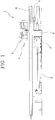
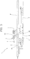
- Further characteristics and advantages of the present invention will more fully emerge from the description of a preferred but not exclusive embodiment of a cutting method for manufactured articles, as illustrated in the accompanying drawings which in figures from 1 to 5 illustrate a schematic lateral view of a machine for cutting manufactured articles which carries out a method for cutting articles according to the present invention. With reference to the accompanying
figures, 1 denotes a machine for cutting manufactured articles "M" able to implement a method for cutting manufactured articles "M" according to the present invention. - The
machine 1 comprises aguide 2 orientated along an advancement direction "A" of a manufactured article "M". Acutting device 3 is associated to theguide 2. In particular, thecutting device 3 is mobile along theguide 2, and is associable to the manufactured article "M" such that it also advances along the advancement direction "A". - Further, the
cutting device 3 is mobile from a stroke start position to a stroke end position. Thecutting device 3 is therefore mobile along the advancement direction such as to perform a cut on the manufactured article "M" in motion. Thecutting device 3 is not described in detail as it is of known type to a person skilled in the art, and is in any case variable according to the specific nature of the manufactured article "M" to be cut. - The
machine 1 further comprises synchronisation means (not illustrated) able to regulate the speed of advancement of thecutting device 3 to make it coincide with the speed of advancement of the manufactured article "M". In particular, the synchronization means comprise detecting means (not illustrated) able to identify a predetermined first cutting zone "Z1 on the manufactured article "M". The first cutting zone will be localized according to the position of a free end "L" of the manufactured article "M" and the required length of the segments "S" to be produced. - The synchronising means further comprise a control device able to position the
cutting device 3 at the first cutting zone "Z1 ". More in general, the control device is able to guide thecutting device 3 on any cutting zone identified by the detecting means. - A machine such as the one described above is further able to collect samples "C" from the manufactured article "M" to be cut, according to the method that will be described in the following. To displace the samples "C" out of the production line, the
machine 1 comprises means forevacuation 4 of a portion "P2" of the manufactured article "M". - According to the present invention, the means for
evacuation 4 are mobile along theguide 2 and are solidly constrained to thecutting device 3, such as to translate along theguide 2 together with thecutting device 3. - In detail, the
machine 1 comprises acarriage 5, mobile along theguide 2, to which thecutting device 3 is fixed. The preferred embodiment shows, by way of example of the means forevacuation 4, achute 6 fixed to thecarriage 5. The method for cutting manufactured articles "M" operates in the following way. Firstly a manufactured article "M" is advanced along an advancement direction "A" at a predetermined speed. The manufactured article "M" to be cut preferably moves at a constant speed. By way of example, the manufactured article "M" can be a tube produced using a continuous process, where there is a need to cut segments "S" of a predetermined length and, in particular, uniform. - The
cutting device 3 is then predisposed, associated to the manufactured article "M" and mobile along the advancement direction "A". Thecutting device 3 is advanced along the advancement direction "A", in particular the speed of advancement of thecutting device 3 is synchronized with the speed of advancement of the manufactured article "M", such as to position thecutting device 3 at a predetermined first cutting zone "Z1" identified on the manufactured article. - The
cutting device 3 is then activated, such as to cut a first portion "P1" of the manufactured article "M". The first portion "P1", once cut, defines the segment "S" under production. - The
cutting device 3 is then retracted, in particular back to the cycle start position. - Note that the steps of synchronization and activation of the
cutting device 3 are comprised between the advancement step and a corresponding retraction step. In this way a single cutting cycle of the manufactured article "M" is defined. In other terms, the cutting cycle comprises the operations required for cutting a single segment "S". The cutting cycle is obviously repeatable any number of times, such as to be able to produce any number of segments "S" of a predetermined length starting from a single manufactured article "M" produced with a continuous process. - In detail, a plurality of advancement steps can be performed as described above, each followed by a corresponding retracting step.
- To extract a sample "C" from the manufactured article "M", the single cutting cycle can optionally comprise further operations.
- In particular, following the activation of the
cutting device 3 it is possible to slow thecutting device 3 down such as to cause it to advance with a slower speed with respect to the speed of advancement of the manufactured article "M". - Note that in the method of the present invention, during the slowing step the speed of advancement of the
cutting device 3 is in a same direction as the speed of advancement of the manufactured article "M". Further, during the slowing step the speed of advancement of thecutting device 3 is lower than the speed of advancement of the manufactured article "M". In other terms, thecutting device 3 does not invert movement thereof during the slowing step, but continues to advance, though at a slow speed. On the basis of production data, in the step following the cut of the length "P1" thecutting device 3 might be commanded to proceed in an opposed direction to the advancement direction of the manufactured article "M". - In particular, following the slowing step, a re-synchronisation step of the
cutting device 3 is carried out. The speed of advancement of thecutting device 3 is newly synchronized with the speed of advancement of the manufactured article "M" such as to position thecutting device 3 at a predetermined second cutting zone "Z2". Thereafter thecutting device 3 is newly activated such as to cut a second portion "Z2" of the manufactured article "M". - The whole operation is carried out with the objective of maintaining the performance of the plant. For this reason, to cut the second portion P2 the
cutting device 3 is activated using working parameters characterised by a speed of execution of the cutting cycle that is significantly greater than the velocity of the usual cycle for the cutting of a first portion P2. In particular, to manage the operation a reconditioning of the cutting parameters is operated using cutting and speed of advancement that are significantly greater than the standard ones used for cutting the sections "S". The reconditioning can be set for one or for both the consecutive cuts according to the performances required by the plant. - In particular, the working parameters can also be used (cutting speed) for cutting the portion P1 immediately preceding the cut of the second portion P2.
- Thereafter, the above-described step of retracting the
cutting device 3 is carried out. - The present invention attains the set aims. In particular, the possibility of repeating the synchronization step within a single cycle enables performing a second cut and collecting a sample of manufactured article having a smaller length, thus avoiding waste.
- Furthermore, as the method comprises two cuts with a single cutting device, further equipment is not necessary and consequently there is a significant reduction in dimensions and costs.
Claims (8)
- A method for cutting manufactured articles (M), comprising the steps of advancing a manufactured article (M) along an advancement direction (A) with a predetermined speed; predisposing a cutting device (3) in a stroke start position, said cutting device (3) being associated with said manufactured article (M) and movable along said advancement direction (A); advancing said cutting device (3) along said advancement direction (A); synchronizing the speed of advancement of said cutting device (3) with the speed of advancement of said manufactured article (M) so as to position said cutting device (3) at a predetermined first cutting zone (Z1) of said manufactured article (M); activating said cutting device (3) so as to cut a first portion (P1) of said manufactured article; characterized in that it comprises, within the same forward step, the further step of slowing down said cutting device (3) so as to advance it with a speed that is lower, null or possibly in an opposed direction, with respect to the speed of advancement of the manufactured article (M), and comprises the further steps of resynchronization of the speed of advancement of said cutting device (3) with the speed of advancement of said manufactured article (M) so as to position said cutting device (3) at a predetermined second cutting zone (Z2) of said manufactured article (M); activating said cutting device (3) so as to cut a second portion (P2) of said manufactured article (M) of shorter length with respect to P1.
- A method for cutting manufactured articles (M) according to claim 1, characterized in that said cutting device (3) for cutting said second portion (P2) can be activated by employing job parameters characterized by speeds for the performance of the cutting cycle that are decidedly higher than the speeds of the usual cycle for cutting a said first portion P1.
- The method for cutting manufactured articles (M) according to claim 2, characterized in that during performance of the cycle mentioned, the said job parameters distinguished by speeds for the performance of the cutting cycle that are decidedly higher than the speeds of the usual cycle for cutting a said first portion P1 can be activated also for cutting the first portion P1 immediately preceding the cutting of the second portion P2.
- The method for cutting manufactured articles (M) according to any one of the preceding claims, characterized in that said resynchronization step follows said step of cutting the first portion (P1).
- A machine (1) for cutting manufactured articles (M), comprising a guide (2) oriented along an advancement direction (A) of a manufactured article (M); a cutting device (3) that is movable along said guide (2) and that can be associated with said manufactured article (M) so as to advance along said advancement direction (A); means for synchronization of the speed of advancement of said cutting device (3) with the speed of advancement of said manufactured article (M) so as to position said cutting device (3) at a predetermined first cutting zone (Z1) of said manufactured article (M) and to cut said manufactured article (M); characterized in that it comprises means for resynchronization arranged so as to resynchronize, within the same cutting cycle, the speed of advancement of said cutting device (3) with the speed of advancement of said manufactured article (M), so as to position said cutting device (3) at a predetermined second cutting zone (Z2) of said manufactured article (M) and to cut a second portion (P2) of said manufactured article (M).
- The machine (1) according to the preceding claim, characterized in that it comprises means for evacuation (4) of a portion of said manufactured article (M); said means for evacuation (4) being movable along said guide (2).
- The machine (1) according to the preceding claim, characterized in that said means for evacuation (4) are solidly constrained to said cutting device (3) so as to translate along said guide (2) together with said cutting device (3).
- The machine (1) for cutting manufactured articles (M) according to claim 8 or 9, characterized in that it comprises a carriage (5) that is movable along said guide (2), said cutting device (3) being fixed to said carriage (5); said means for evacuation (4) comprising for example a chute (6) fixed to said carriage (5).
Applications Claiming Priority (2)
| Application Number | Priority Date | Filing Date | Title |
|---|---|---|---|
| IT000082A ITMO20120082A1 (en) | 2012-03-28 | 2012-03-28 | METHOD FOR CUTTING MANUFACTURED FLIGHTS. |
| PCT/IB2013/052486 WO2013144896A1 (en) | 2012-03-28 | 2013-03-28 | A method for cutting moving manufactured articles |
Publications (2)
| Publication Number | Publication Date |
|---|---|
| EP2830800A1 EP2830800A1 (en) | 2015-02-04 |
| EP2830800B1 true EP2830800B1 (en) | 2017-05-03 |
Family
ID=46548661
Family Applications (1)
| Application Number | Title | Priority Date | Filing Date |
|---|---|---|---|
| EP13723234.4A Active EP2830800B1 (en) | 2012-03-28 | 2013-03-28 | A method for cutting moving manufactured articles |
Country Status (10)
| Country | Link |
|---|---|
| US (1) | US20150082954A1 (en) |
| EP (1) | EP2830800B1 (en) |
| JP (1) | JP6034482B2 (en) |
| BR (1) | BR112014019315A8 (en) |
| CA (1) | CA2863495C (en) |
| ES (1) | ES2626446T3 (en) |
| IT (1) | ITMO20120082A1 (en) |
| MX (1) | MX348583B (en) |
| PL (1) | PL2830800T3 (en) |
| WO (1) | WO2013144896A1 (en) |
Families Citing this family (2)
| Publication number | Priority date | Publication date | Assignee | Title |
|---|---|---|---|---|
| ITMO20130332A1 (en) * | 2013-12-06 | 2015-06-07 | Oto S P A | CUTTING MACHINE |
| CN105458301B (en) * | 2016-01-12 | 2018-07-20 | 大连富地重工机械制造有限公司 | A kind of new method of the continuously shaped material of the synchronous fixed ruler cutting of more vehicle series connection |
Family Cites Families (9)
| Publication number | Priority date | Publication date | Assignee | Title |
|---|---|---|---|---|
| US3639970A (en) * | 1969-10-02 | 1972-02-08 | Phillips Petroleum Co | Method and apparatus for forming plastic-lined metal conduit |
| DE2428219C2 (en) * | 1974-06-11 | 1984-11-22 | L. Schuler GmbH, 7320 Göppingen | Device for controlling and regulating the cutting distance and synchronism on a cutting device processing strip material |
| JPS5162480A (en) * | 1974-11-27 | 1976-05-31 | Honda Kinzoku Kogyo Kk | RANNINGUDAISHAARINGUMASHIN |
| JPS58217215A (en) * | 1982-06-04 | 1983-12-17 | Ube Ind Ltd | Running type shearing device |
| IT1171937B (en) * | 1983-06-21 | 1987-06-10 | Sica Spa | EQUIPMENT AND PROCEDURE FOR CHECKING THE WORKING PHASES OF A MOBILE CUTTING DEVICE ON CONTINUOUS EXTRUDED PIPES |
| JPS6234716A (en) * | 1985-08-02 | 1987-02-14 | Nasuko Kk | Traveling machine tool |
| JPH0618739Y2 (en) * | 1989-05-30 | 1994-05-18 | 日鐵建材工業株式会社 | Cut product removal device for running cutting machine |
| ITMO20030087A1 (en) * | 2003-03-27 | 2004-09-28 | Oto Mills Spa | CONTINUOUS CYCLE FLYING CUTTING MACHINE OF WELDED TUBES. |
| ITRN20070034A1 (en) * | 2007-06-27 | 2008-12-28 | Sica Spa | MACHINE AND CUTTING METHOD OF A CONTINUOUS EXTRUDED TUBE IN MINOR SPOTS AND PREDETERMINED LENGTH. |
-
2012
- 2012-03-28 IT IT000082A patent/ITMO20120082A1/en unknown
-
2013
- 2013-03-28 EP EP13723234.4A patent/EP2830800B1/en active Active
- 2013-03-28 PL PL13723234T patent/PL2830800T3/en unknown
- 2013-03-28 ES ES13723234.4T patent/ES2626446T3/en active Active
- 2013-03-28 BR BR112014019315A patent/BR112014019315A8/en not_active Application Discontinuation
- 2013-03-28 US US14/385,656 patent/US20150082954A1/en not_active Abandoned
- 2013-03-28 WO PCT/IB2013/052486 patent/WO2013144896A1/en not_active Ceased
- 2013-03-28 CA CA2863495A patent/CA2863495C/en not_active Expired - Fee Related
- 2013-03-28 JP JP2015502535A patent/JP6034482B2/en not_active Expired - Fee Related
- 2013-03-28 MX MX2014011221A patent/MX348583B/en active IP Right Grant
Also Published As
| Publication number | Publication date |
|---|---|
| CA2863495A1 (en) | 2013-10-03 |
| EP2830800A1 (en) | 2015-02-04 |
| PL2830800T3 (en) | 2017-09-29 |
| JP2015511546A (en) | 2015-04-20 |
| ES2626446T3 (en) | 2017-07-25 |
| CA2863495C (en) | 2017-07-04 |
| ITMO20120082A1 (en) | 2013-09-29 |
| WO2013144896A1 (en) | 2013-10-03 |
| BR112014019315A8 (en) | 2017-07-11 |
| JP6034482B2 (en) | 2016-11-30 |
| BR112014019315A2 (en) | 2017-06-20 |
| MX348583B (en) | 2017-06-19 |
| US20150082954A1 (en) | 2015-03-26 |
| MX2014011221A (en) | 2014-11-10 |
Similar Documents
| Publication | Publication Date | Title |
|---|---|---|
| CN105458301B (en) | A kind of new method of the continuously shaped material of the synchronous fixed ruler cutting of more vehicle series connection | |
| US20080202299A1 (en) | Cutting device for substantially linear workpieces and method for cutting substantially linear workpieces | |
| EP2881214B1 (en) | Tube cutting-off machine | |
| CN202079404U (en) | Automatic punching production line | |
| US20210187771A1 (en) | Method and apparatus for cutting a pipe made from thermoplastic material | |
| JP6022640B1 (en) | Coil material processing equipment | |
| CA2863495C (en) | A method for cutting moving manufactured articles | |
| CA2842907C (en) | Rolling mill and rolling method | |
| CN105033115A (en) | Steel wire straightening cutting machine | |
| EP0129515A3 (en) | Apparatus and method for controlling the working steps of a movable cutter for extruded tubes | |
| US7096706B2 (en) | Drawing apparatus and method of operating same | |
| CN102172812B (en) | Hollow aluminium division bar continuous moulding method | |
| US3107404A (en) | Cutting of continuous cast bars | |
| US4920779A (en) | Bending apparatus | |
| CN114302798B (en) | Apparatus and method for cutting plastic profiles to length | |
| EP1396296B1 (en) | Method for cropping to size and optionally bending profiled elements with bending and shaping machines, particularly profiled elements supplied in bar form | |
| CN101214525A (en) | Device and method for rapidly pressing ring parts without chips | |
| CN104552395A (en) | Door and window glazing bead cutting tool and technological method | |
| CN202045296U (en) | Nesting wrap-around device of composite profile member | |
| CN208728587U (en) | A kind of new energy cable shield silk screen fixed-length cutting device | |
| CN103831476A (en) | Thermal cutting machine for cutting cylindrical aluminum bar | |
| EP3055092B1 (en) | Single shear for cutting and conveying multiple rolled sections | |
| EP3670049A1 (en) | Weld bead cutting device | |
| SU1066705A2 (en) | Apparatus for producing blanks of knitted fabric latch needle from wire bundle | |
| CN117226895A (en) | An automatic cutting device for insulation boards |
Legal Events
| Date | Code | Title | Description |
|---|---|---|---|
| PUAI | Public reference made under article 153(3) epc to a published international application that has entered the european phase |
Free format text: ORIGINAL CODE: 0009012 |
|
| 17P | Request for examination filed |
Effective date: 20140723 |
|
| AK | Designated contracting states |
Kind code of ref document: A1 Designated state(s): AL AT BE BG CH CY CZ DE DK EE ES FI FR GB GR HR HU IE IS IT LI LT LU LV MC MK MT NL NO PL PT RO RS SE SI SK SM TR |
|
| AX | Request for extension of the european patent |
Extension state: BA ME |
|
| DAX | Request for extension of the european patent (deleted) | ||
| GRAP | Despatch of communication of intention to grant a patent |
Free format text: ORIGINAL CODE: EPIDOSNIGR1 |
|
| INTG | Intention to grant announced |
Effective date: 20161129 |
|
| RIN1 | Information on inventor provided before grant (corrected) |
Inventor name: ANESI, ANDREA Inventor name: VECCHINI, GIANLUCA Inventor name: CHEZZI, ALEARDO |
|
| GRAS | Grant fee paid |
Free format text: ORIGINAL CODE: EPIDOSNIGR3 |
|
| GRAA | (expected) grant |
Free format text: ORIGINAL CODE: 0009210 |
|
| AK | Designated contracting states |
Kind code of ref document: B1 Designated state(s): AL AT BE BG CH CY CZ DE DK EE ES FI FR GB GR HR HU IE IS IT LI LT LU LV MC MK MT NL NO PL PT RO RS SE SI SK SM TR |
|
| REG | Reference to a national code |
Ref country code: GB Ref legal event code: FG4D |
|
| REG | Reference to a national code |
Ref country code: AT Ref legal event code: REF Ref document number: 889433 Country of ref document: AT Kind code of ref document: T Effective date: 20170515 Ref country code: CH Ref legal event code: EP |
|
| REG | Reference to a national code |
Ref country code: CH Ref legal event code: NV Representative=s name: BUGNION S.A., CH Ref country code: IE Ref legal event code: FG4D |
|
| REG | Reference to a national code |
Ref country code: RO Ref legal event code: EPE |
|
| REG | Reference to a national code |
Ref country code: NL Ref legal event code: FP |
|
| REG | Reference to a national code |
Ref country code: DE Ref legal event code: R096 Ref document number: 602013020608 Country of ref document: DE |
|
| REG | Reference to a national code |
Ref country code: SE Ref legal event code: TRGR |
|
| REG | Reference to a national code |
Ref country code: ES Ref legal event code: FG2A Ref document number: 2626446 Country of ref document: ES Kind code of ref document: T3 Effective date: 20170725 |
|
| REG | Reference to a national code |
Ref country code: LT Ref legal event code: MG4D |
|
| PG25 | Lapsed in a contracting state [announced via postgrant information from national office to epo] |
Ref country code: HR Free format text: LAPSE BECAUSE OF FAILURE TO SUBMIT A TRANSLATION OF THE DESCRIPTION OR TO PAY THE FEE WITHIN THE PRESCRIBED TIME-LIMIT Effective date: 20170503 Ref country code: LT Free format text: LAPSE BECAUSE OF FAILURE TO SUBMIT A TRANSLATION OF THE DESCRIPTION OR TO PAY THE FEE WITHIN THE PRESCRIBED TIME-LIMIT Effective date: 20170503 Ref country code: GR Free format text: LAPSE BECAUSE OF FAILURE TO SUBMIT A TRANSLATION OF THE DESCRIPTION OR TO PAY THE FEE WITHIN THE PRESCRIBED TIME-LIMIT Effective date: 20170804 Ref country code: NO Free format text: LAPSE BECAUSE OF FAILURE TO SUBMIT A TRANSLATION OF THE DESCRIPTION OR TO PAY THE FEE WITHIN THE PRESCRIBED TIME-LIMIT Effective date: 20170803 |
|
| PG25 | Lapsed in a contracting state [announced via postgrant information from national office to epo] |
Ref country code: RS Free format text: LAPSE BECAUSE OF FAILURE TO SUBMIT A TRANSLATION OF THE DESCRIPTION OR TO PAY THE FEE WITHIN THE PRESCRIBED TIME-LIMIT Effective date: 20170503 Ref country code: IS Free format text: LAPSE BECAUSE OF FAILURE TO SUBMIT A TRANSLATION OF THE DESCRIPTION OR TO PAY THE FEE WITHIN THE PRESCRIBED TIME-LIMIT Effective date: 20170903 Ref country code: BG Free format text: LAPSE BECAUSE OF FAILURE TO SUBMIT A TRANSLATION OF THE DESCRIPTION OR TO PAY THE FEE WITHIN THE PRESCRIBED TIME-LIMIT Effective date: 20170803 Ref country code: LV Free format text: LAPSE BECAUSE OF FAILURE TO SUBMIT A TRANSLATION OF THE DESCRIPTION OR TO PAY THE FEE WITHIN THE PRESCRIBED TIME-LIMIT Effective date: 20170503 |
|
| PG25 | Lapsed in a contracting state [announced via postgrant information from national office to epo] |
Ref country code: SK Free format text: LAPSE BECAUSE OF FAILURE TO SUBMIT A TRANSLATION OF THE DESCRIPTION OR TO PAY THE FEE WITHIN THE PRESCRIBED TIME-LIMIT Effective date: 20170503 Ref country code: CZ Free format text: LAPSE BECAUSE OF FAILURE TO SUBMIT A TRANSLATION OF THE DESCRIPTION OR TO PAY THE FEE WITHIN THE PRESCRIBED TIME-LIMIT Effective date: 20170503 Ref country code: DK Free format text: LAPSE BECAUSE OF FAILURE TO SUBMIT A TRANSLATION OF THE DESCRIPTION OR TO PAY THE FEE WITHIN THE PRESCRIBED TIME-LIMIT Effective date: 20170503 Ref country code: EE Free format text: LAPSE BECAUSE OF FAILURE TO SUBMIT A TRANSLATION OF THE DESCRIPTION OR TO PAY THE FEE WITHIN THE PRESCRIBED TIME-LIMIT Effective date: 20170503 |
|
| REG | Reference to a national code |
Ref country code: DE Ref legal event code: R097 Ref document number: 602013020608 Country of ref document: DE |
|
| PG25 | Lapsed in a contracting state [announced via postgrant information from national office to epo] |
Ref country code: SM Free format text: LAPSE BECAUSE OF FAILURE TO SUBMIT A TRANSLATION OF THE DESCRIPTION OR TO PAY THE FEE WITHIN THE PRESCRIBED TIME-LIMIT Effective date: 20170503 |
|
| PLBE | No opposition filed within time limit |
Free format text: ORIGINAL CODE: 0009261 |
|
| STAA | Information on the status of an ep patent application or granted ep patent |
Free format text: STATUS: NO OPPOSITION FILED WITHIN TIME LIMIT |
|
| REG | Reference to a national code |
Ref country code: FR Ref legal event code: PLFP Year of fee payment: 6 |
|
| 26N | No opposition filed |
Effective date: 20180206 |
|
| PG25 | Lapsed in a contracting state [announced via postgrant information from national office to epo] |
Ref country code: SI Free format text: LAPSE BECAUSE OF FAILURE TO SUBMIT A TRANSLATION OF THE DESCRIPTION OR TO PAY THE FEE WITHIN THE PRESCRIBED TIME-LIMIT Effective date: 20170503 |
|
| PG25 | Lapsed in a contracting state [announced via postgrant information from national office to epo] |
Ref country code: MC Free format text: LAPSE BECAUSE OF FAILURE TO SUBMIT A TRANSLATION OF THE DESCRIPTION OR TO PAY THE FEE WITHIN THE PRESCRIBED TIME-LIMIT Effective date: 20170503 |
|
| REG | Reference to a national code |
Ref country code: BE Ref legal event code: MM Effective date: 20180331 |
|
| REG | Reference to a national code |
Ref country code: IE Ref legal event code: MM4A |
|
| PG25 | Lapsed in a contracting state [announced via postgrant information from national office to epo] |
Ref country code: LU Free format text: LAPSE BECAUSE OF NON-PAYMENT OF DUE FEES Effective date: 20180328 |
|
| PG25 | Lapsed in a contracting state [announced via postgrant information from national office to epo] |
Ref country code: IE Free format text: LAPSE BECAUSE OF NON-PAYMENT OF DUE FEES Effective date: 20180328 |
|
| PG25 | Lapsed in a contracting state [announced via postgrant information from national office to epo] |
Ref country code: BE Free format text: LAPSE BECAUSE OF NON-PAYMENT OF DUE FEES Effective date: 20180331 |
|
| REG | Reference to a national code |
Ref country code: AT Ref legal event code: UEP Ref document number: 889433 Country of ref document: AT Kind code of ref document: T Effective date: 20170503 |
|
| PGFP | Annual fee paid to national office [announced via postgrant information from national office to epo] |
Ref country code: PL Payment date: 20190220 Year of fee payment: 7 Ref country code: FI Payment date: 20190320 Year of fee payment: 7 Ref country code: FR Payment date: 20190328 Year of fee payment: 7 Ref country code: PL Payment date: 20190306 Year of fee payment: 7 Ref country code: GB Payment date: 20190327 Year of fee payment: 7 Ref country code: RO Payment date: 20190322 Year of fee payment: 7 |
|
| PGFP | Annual fee paid to national office [announced via postgrant information from national office to epo] |
Ref country code: TR Payment date: 20190314 Year of fee payment: 7 Ref country code: SE Payment date: 20190328 Year of fee payment: 7 Ref country code: NL Payment date: 20190325 Year of fee payment: 7 |
|
| PGFP | Annual fee paid to national office [announced via postgrant information from national office to epo] |
Ref country code: DE Payment date: 20190531 Year of fee payment: 7 Ref country code: ES Payment date: 20190425 Year of fee payment: 7 |
|
| PG25 | Lapsed in a contracting state [announced via postgrant information from national office to epo] |
Ref country code: MT Free format text: LAPSE BECAUSE OF NON-PAYMENT OF DUE FEES Effective date: 20180328 |
|
| PG25 | Lapsed in a contracting state [announced via postgrant information from national office to epo] |
Ref country code: HU Free format text: LAPSE BECAUSE OF FAILURE TO SUBMIT A TRANSLATION OF THE DESCRIPTION OR TO PAY THE FEE WITHIN THE PRESCRIBED TIME-LIMIT; INVALID AB INITIO Effective date: 20130328 Ref country code: PT Free format text: LAPSE BECAUSE OF FAILURE TO SUBMIT A TRANSLATION OF THE DESCRIPTION OR TO PAY THE FEE WITHIN THE PRESCRIBED TIME-LIMIT Effective date: 20170503 |
|
| PG25 | Lapsed in a contracting state [announced via postgrant information from national office to epo] |
Ref country code: MK Free format text: LAPSE BECAUSE OF NON-PAYMENT OF DUE FEES Effective date: 20170503 Ref country code: CY Free format text: LAPSE BECAUSE OF FAILURE TO SUBMIT A TRANSLATION OF THE DESCRIPTION OR TO PAY THE FEE WITHIN THE PRESCRIBED TIME-LIMIT Effective date: 20170503 |
|
| PG25 | Lapsed in a contracting state [announced via postgrant information from national office to epo] |
Ref country code: AL Free format text: LAPSE BECAUSE OF FAILURE TO SUBMIT A TRANSLATION OF THE DESCRIPTION OR TO PAY THE FEE WITHIN THE PRESCRIBED TIME-LIMIT Effective date: 20170503 |
|
| REG | Reference to a national code |
Ref country code: DE Ref legal event code: R119 Ref document number: 602013020608 Country of ref document: DE |
|
| REG | Reference to a national code |
Ref country code: FI Ref legal event code: MAE |
|
| PG25 | Lapsed in a contracting state [announced via postgrant information from national office to epo] |
Ref country code: FI Free format text: LAPSE BECAUSE OF NON-PAYMENT OF DUE FEES Effective date: 20200328 Ref country code: RO Free format text: LAPSE BECAUSE OF NON-PAYMENT OF DUE FEES Effective date: 20200328 |
|
| REG | Reference to a national code |
Ref country code: CH Ref legal event code: PL |
|
| REG | Reference to a national code |
Ref country code: NL Ref legal event code: MM Effective date: 20200401 |
|
| PG25 | Lapsed in a contracting state [announced via postgrant information from national office to epo] |
Ref country code: NL Free format text: LAPSE BECAUSE OF NON-PAYMENT OF DUE FEES Effective date: 20200401 |
|
| PG25 | Lapsed in a contracting state [announced via postgrant information from national office to epo] |
Ref country code: SE Free format text: LAPSE BECAUSE OF NON-PAYMENT OF DUE FEES Effective date: 20200329 Ref country code: FR Free format text: LAPSE BECAUSE OF NON-PAYMENT OF DUE FEES Effective date: 20200331 Ref country code: LI Free format text: LAPSE BECAUSE OF NON-PAYMENT OF DUE FEES Effective date: 20200331 Ref country code: CH Free format text: LAPSE BECAUSE OF NON-PAYMENT OF DUE FEES Effective date: 20200331 Ref country code: DE Free format text: LAPSE BECAUSE OF NON-PAYMENT OF DUE FEES Effective date: 20201001 |
|
| GBPC | Gb: european patent ceased through non-payment of renewal fee |
Effective date: 20200328 |
|
| PG25 | Lapsed in a contracting state [announced via postgrant information from national office to epo] |
Ref country code: GB Free format text: LAPSE BECAUSE OF NON-PAYMENT OF DUE FEES Effective date: 20200328 |
|
| REG | Reference to a national code |
Ref country code: ES Ref legal event code: FD2A Effective date: 20210812 |
|
| PG25 | Lapsed in a contracting state [announced via postgrant information from national office to epo] |
Ref country code: ES Free format text: LAPSE BECAUSE OF NON-PAYMENT OF DUE FEES Effective date: 20200329 |
|
| PG25 | Lapsed in a contracting state [announced via postgrant information from national office to epo] |
Ref country code: TR Free format text: LAPSE BECAUSE OF NON-PAYMENT OF DUE FEES Effective date: 20200328 |
|
| PG25 | Lapsed in a contracting state [announced via postgrant information from national office to epo] |
Ref country code: PL Free format text: LAPSE BECAUSE OF NON-PAYMENT OF DUE FEES Effective date: 20200328 |
|
| PGFP | Annual fee paid to national office [announced via postgrant information from national office to epo] |
Ref country code: AT Payment date: 20230331 Year of fee payment: 11 |
|
| REG | Reference to a national code |
Ref country code: AT Ref legal event code: MM01 Ref document number: 889433 Country of ref document: AT Kind code of ref document: T Effective date: 20240328 |
|
| PG25 | Lapsed in a contracting state [announced via postgrant information from national office to epo] |
Ref country code: AT Free format text: LAPSE BECAUSE OF NON-PAYMENT OF DUE FEES Effective date: 20240328 |
|
| PG25 | Lapsed in a contracting state [announced via postgrant information from national office to epo] |
Ref country code: AT Free format text: LAPSE BECAUSE OF NON-PAYMENT OF DUE FEES Effective date: 20240328 |
|
| PGFP | Annual fee paid to national office [announced via postgrant information from national office to epo] |
Ref country code: IT Payment date: 20250327 Year of fee payment: 13 |