EP2830376B1 - Method and device for determining epdcch resources - Google Patents
Method and device for determining epdcch resources Download PDFInfo
- Publication number
- EP2830376B1 EP2830376B1 EP13764420.9A EP13764420A EP2830376B1 EP 2830376 B1 EP2830376 B1 EP 2830376B1 EP 13764420 A EP13764420 A EP 13764420A EP 2830376 B1 EP2830376 B1 EP 2830376B1
- Authority
- EP
- European Patent Office
- Prior art keywords
- epdcch
- res
- subframe
- configuration
- ports
- Prior art date
- Legal status (The legal status is an assumption and is not a legal conclusion. Google has not performed a legal analysis and makes no representation as to the accuracy of the status listed.)
- Active
Links
Images


Classifications
-
- H—ELECTRICITY
- H04—ELECTRIC COMMUNICATION TECHNIQUE
- H04W—WIRELESS COMMUNICATION NETWORKS
- H04W72/00—Local resource management
- H04W72/04—Wireless resource allocation
-
- H—ELECTRICITY
- H04—ELECTRIC COMMUNICATION TECHNIQUE
- H04W—WIRELESS COMMUNICATION NETWORKS
- H04W72/00—Local resource management
- H04W72/20—Control channels or signalling for resource management
- H04W72/23—Control channels or signalling for resource management in the downlink direction of a wireless link, i.e. towards a terminal
-
- H—ELECTRICITY
- H04—ELECTRIC COMMUNICATION TECHNIQUE
- H04B—TRANSMISSION
- H04B7/00—Radio transmission systems, i.e. using radiation field
- H04B7/24—Radio transmission systems, i.e. using radiation field for communication between two or more posts
- H04B7/26—Radio transmission systems, i.e. using radiation field for communication between two or more posts at least one of which is mobile
-
- H—ELECTRICITY
- H04—ELECTRIC COMMUNICATION TECHNIQUE
- H04L—TRANSMISSION OF DIGITAL INFORMATION, e.g. TELEGRAPHIC COMMUNICATION
- H04L5/00—Arrangements affording multiple use of the transmission path
- H04L5/003—Arrangements for allocating sub-channels of the transmission path
- H04L5/0048—Allocation of pilot signals, i.e. of signals known to the receiver
-
- H—ELECTRICITY
- H04—ELECTRIC COMMUNICATION TECHNIQUE
- H04L—TRANSMISSION OF DIGITAL INFORMATION, e.g. TELEGRAPHIC COMMUNICATION
- H04L5/00—Arrangements affording multiple use of the transmission path
- H04L5/003—Arrangements for allocating sub-channels of the transmission path
- H04L5/0053—Allocation of signaling, i.e. of overhead other than pilot signals
-
- H—ELECTRICITY
- H04—ELECTRIC COMMUNICATION TECHNIQUE
- H04L—TRANSMISSION OF DIGITAL INFORMATION, e.g. TELEGRAPHIC COMMUNICATION
- H04L5/00—Arrangements affording multiple use of the transmission path
- H04L5/0091—Signaling for the administration of the divided path
- H04L5/0094—Indication of how sub-channels of the path are allocated
-
- H—ELECTRICITY
- H04—ELECTRIC COMMUNICATION TECHNIQUE
- H04W—WIRELESS COMMUNICATION NETWORKS
- H04W72/00—Local resource management
-
- H—ELECTRICITY
- H04—ELECTRIC COMMUNICATION TECHNIQUE
- H04L—TRANSMISSION OF DIGITAL INFORMATION, e.g. TELEGRAPHIC COMMUNICATION
- H04L5/00—Arrangements affording multiple use of the transmission path
- H04L5/0001—Arrangements for dividing the transmission path
- H04L5/0014—Three-dimensional division
- H04L5/0023—Time-frequency-space
Definitions
- the present disclosure relates to radio communications techniques, and more particularly, to a method and an apparatus for determining ePDCCH resources.
- PDCCH physical downlink control channel
- OFDM orthogonal frequency division multiplexing
- a control area used for transmitting the PDCCH consists of logical control channel elements (CCEs), wherein one CCE consists of 9 RE groups (REG).
- CCEs logical control channel elements
- REG RE groups
- One REG consists of 4 resource elements (REs) which are the same in the time domain and are adjacent in the frequency domain.
- the REs constituting the REG do not include those used for transmitting common reference signals.
- Detailed definition of the REG is as shown in Figure 2 .
- Downlink control information is also transmitted taking CCE as a transmission unit.
- DCI Downlink control information
- UE user equipment
- M logically continuous CCEs.
- the value of M may be 1, 2, 4 or 8, which is referred to as aggregation level.
- the UE performs a blind detection in the control area, determines whether there is PDCCH transmitted for the UE.
- the blind detection is to perform decoding attempts with respect to different DCI formats and CCE aggregation levels using radio network temporary identity (RNTI) of the UE. If the decoding is correct, the DCI with respect to the UE is received.
- the LTE UE needs to perform the blind detection in the control area of each downlink subframe in a discontinuous reception (DRX) status and searches for the PDCCH.
- DRX discontinuous reception
- Figures 3a , 3b and 3c show configurations of channel state information-reference signal (CSI-RS) in an LTE Rel-10 system, wherein Figure 3a shows the configuration for 2 ports, Figure 3b shows the configuration for 4 ports, and Figure 3c shows multiplexing manner for 8 ports.
- the number of CSI-RS ports and their resource positions are configured independently for each user. Thus, for different users, different resource positions may be occupied.
- Each user may further be configured with zero-power CSI-RS resources which are configured following the configuration of 4 CSI-RS ports. No signal is transmitted on the zero-power CSI-RS resources.
- the zero-power CSI-RS is configured via radio resource control (RRC) signaling. If a 4 port CSI-RS pattern is configured to be zero-power CSI-RS, it indicates that the user regards that no physical downlink shared channel (PDSCH) data is transmitted on these REs.
- RRC radio resource control
- enhanced PDCCH is transmitted in the PDSCH area (i.e., data area).
- the number of available REs in the PDSCH area may be different, i.e., the number of REs used for transmitting the ePDCCH is different, which has a relatively large impact to demodulation performance of control signaling.
- the present invention provides a method for determining enhanced physical downlink control channel, ePDCCH, resources according to claim 1 and a corresponding apparatus according to claim 3.
- ePDCCH enhanced physical downlink control channel
- number of symbols occupied by PDCCH, number of CRS ports and number of DMRS ports and CSI-RS configuration in a subframe are determined first. Then, according to the number of symbols occupied by the PDCCH, the number of CRS ports, the number of DMRS ports and the CSI-RS configuration, it is possible to determine the resources for transmitting ePDCCH in the PDSCH area of the subframe.
- size of a minimum resource unit of ePDCCH (i.e., the number of REs included) is defined first. Then, according to the number of REs available for transmitting the ePDCCH in the PDSCH area in a subframe under each configuration, it is possible to obtain the number of resource units occupied by the ePDCCH in the subframe under the configuration.
- eCCE, eREG and resource block which is obtained through average division of a PRB pair are taken as exemplary minimum resource units of the ePDCCH to describe the present disclosure.
- Example 1 describes a method for determining number of ePDCCH resource units when the eCCE is taken as the minimum resource unit of the ePDCCH.
- the size of the eCCE may be defined approximately the same as the CCE in the LTE Rel-8/9/10 system.
- the size of the eCCE in the subframe may change under different configurations, which is mainly determined by the configuration of the subframe (the number of available REs in the PDSCH area of the subframe may vary under different configurations).
- the sizes of the eCCEs may be the same or have slight difference, which is mainly determined by a mapping manner from the eCCE to the REs.
- one PRB pair includes an integer number of eCCEs. The number is denoted by M. The value of M may be 2, 3 or 4.
- the value of M is determined by the number of REs available for the ePDCCH in one PRB pair. For example, it is defined that one eCCE includes approximately 30 REs. Thus, if the number of REs available for the ePDCCH in one PRB pair is less than 90, the PRB pair includes 2 eCCEs. If the number of REs available for the ePDCCH in one PRB pair is between 90 and 120, the PRB pair includes 3 eCCEs. If the number of REs available for the ePDCCH in one PRB pair is between 120 and 150, the PRB pair includes 4 eCCEs, and so on.
- Figures 4a, 4b and 4c respectively show the size of the eCCE defined by the example of the present disclosure, the number and the distribution of the eCCEs included in the PRB pair under various CSI-RS configurations.
- one PRB pair occupies 14 OFDM symbols (symbols 0 ⁇ 13) in the time domain, and occupies 12 subcarriers in the frequency domain (subcarriers 0 ⁇ 11), wherein each small rectangle represents an RE.
- the first three symbols (symbols 0 ⁇ 2) in the PRB pair are occupied by "conventional PDCCH (i.e., PDCCH in LTE Rel-8/9/10 system)", the data area occupies other symbols (symbols 3 ⁇ 13).
- the rectangles filled by slanted lines represent REs occupied by four CRS (cell reference signal, i.e., common reference signal) ports.
- the rectangles filled with horizontal lines represent REs occupied by Demodulation reference signal (DMRS).
- the rectangles filled with vertical lines represent REs occupied by CSI-RS.
- 52 RE resources are remained in the data area (e.g., the REs denoted by the black rectangles).
- the PRB pair includes 2 eCCEs. Therefore, the PRB pair as shown in Figure 4a includes two eCCEs, each of which includes 26 REs.
- the available REs are divided into two parts, an upper part and a lower part.
- the 26 REs in the upper part form one eCCE, and the 26 REs in the lower part form another eCCE.
- the above mapping from the eCCE to the REs is just an example. The mapping may be implemented differently and is not restricted in the present disclosure.
- the first two symbols in the PRB pair are occupied by the "conventional PDCCH".
- the rectangles filled with slanted lines represent the REs occupied by 2 CRS ports.
- the rectangles filled with horizontal lines represent REs occupied by the DMRS.
- the rectangles filled with vertical lines represent REs (6 REs in all) occupied by the CSI-RS.
- 102 RE resources are remained in the data area. If it is defined that one eCCE includes approximately 30 REs, and in the case that the number of REs available for the ePDCCH in one PRB pair is between 90 and 120, the PRB pair includes 3 eCCEs.
- the PRB pair as shown in Figure 4b includes 3 eCCEs, each of which includes 34 REs.
- the mapping from the eCCE to the REs in Figure 4b is as follows: the available REs in the data area are divided into three parts: an upper part, a middle part and a lower part.
- the REs in each part form one eCCE.
- each of the upper two eCCE includes 35 REs and the lowest eCCE includes 32 REs.
- the mapping may be implemented via other manners in which the number of REs included in each eCCE may be different from the above example.
- the number of the REs is related to the adopted mapping manner.
- the number of REs available for the ePDCCH in the PRB pair is 90. If it is defined that one eCCE includes no more than 30 REs, in the case that the number of available REs for the ePDCCH in one PRB pair is 90 ⁇ 120, the PRB pair shown in Figure 4c includes 3 eCCEs. According to a mapping similar as Figure 4b , one eCCE includes approximately 30 REs.
- Example 2 describes a method for determining the number of ePDCCH resource units when eREG is taken as the minimum resource unit of the ePDCCH.
- the eREG is taken as the minimum resource unit of the ePDCCH, it is possible to define the size of the eREG to be the same as the REG in the LTE Rel-8/9/10 system (includes 4 REs) or define the size of the eREG to other values.
- the number of REs included in the eREG is fixed. When different mapping manners (mapping from eREG to REs) are adopted, the number of eREGs in one PRB pair under the same configuration may change.
- the data area includes 52 REs available for the ePDCCH. If it is defined that one eREG includes 4 REs and the mapping manner is 4 REs adjacent in the frequency domain constitute a group, there are 13 eREGs altogether.
- the data area includes 102 REs available for the ePDCCH, if the same mapping manner is adopted, there are 23 eREGs altogether (there are some REs cannot be used for ePDCCH transmission).
- the number of eREGs in one PRB pair may be different from that of the above mapping manner.
- the number of REs cannot be used for ePDCCH transmission may be smaller than that of the frequency-domain continuous mapping manner or the slanted mapping manner.
- the number of REs available for transmitting the ePDCCH in the PDSCH area may change.
- the present disclosure may define in standards the resource mapping manner, the size of the minimum resource unit of the ePDCCH, and define, under the defined resource mapping manner, the number of the minimum resource units (eCCEs or eREGs) of the ePDCCH for each configuration of the number of PDCCH symbols, the number of CRS ports, the number of DMRS ports and the CSI-RS configuration.
- the present disclosure may define in the standards the resource mapping manner and the size of the minimum resource unit of the ePDCCH, and may define under the defined resource mapping manner, the number of the minimum resource units (eCCEs or eREGs) of the ePDCCH for each number of REs available for transmitting the ePDCCH (the number of REs is determined by the number of PDCCH symbols, number of CRS ports, number of DMRS ports and the CSI-RS configuration). For example, the number of REs available for transmitting the E-PDCCH in one PRB pair is N, the number of eCCEs is M.
- the values may be defined in the standards. Thus, UE is not required to be additionally notified about the values. The values may also be notified to eNB or UE by system via signaling.
- Example 3 describes a method for determining the number of ePDCCH resource units if a resource block obtained by average division is taken as the minimum resource unit of the ePDCCH.
- the 144 REs in the PRB pair may be averagely divided into 8, 12, 16, 24 or 36 resource blocks.
- such a resource block is taken as the minimum resource block for the ePDCCH to allocate resources for the ePDCCH.
- first three symbols are occupied by the PDCCH.
- There are 4 CRS ports (as shown by rectangles filled with slanted lines).
- the REs occupied by the DMRS are represented by the rectangles filled with horizontal lines.
- the REs occupied by the CSI-RS are represented by the rectangles filled with vertical lines.
- the first symbol is occupied by the PDCCH.
- There are 2 CRS ports (as shown by rectangles filled with slanted lines).
- the REs occupied by the DMRS are represented by the rectangles filled with horizontal lines.
- the REs occupied by the CSI-RS are represented by the rectangles filled with vertical lines.
- One PRB pair as shown in Figures 5a and 5b is divided into 8 resource blocks.
- Figures 5a and 5b divide one PRB pair into the same number of resource blocks, the REs which are actually available for transmitting the ePDCCH are shown by the white rectangles, the sizes (i.e., numbers) of these REs are different in the two Figures.
- a requirement on the size of the resource block (i.e., the number of REs in one resource block) for transmitting the ePDCCH may be defined in advance.
- the division manner of the PRB pair i.e., the number of resource blocks occupied by the ePDCCH in the subframe may be determined according to the size of the resource block for transmitting the ePDCCH defined in advance.
- the resource block used for transmitting the ePDCCH includes approximately 12 REs, at least 10 REs.
- the PRB pair is divided into 8 resource blocks, there may be some resource blocks which include less than 10 resource blocks, which does not meet the requirement.
- the PRB pair may be divided into 8 resource blocks.
- Figure 6 shows an example of an eNB allocating for UE resources for transmitting the ePDCCH according to the present disclosure.
- an evolution NodeB (eNB) side or a UE side needs to determine the number of symbols occupied by the PDCCH, number of CRS ports, number of DMRS ports and the CSI-RS configuration (block 601), and then determines the number of REs available for transmitting the ePDCCH in the PDSCH area of the subframe according to the above information (block 602).
- the number of minimum resource units of the ePDCCH may be determined according to the number of REs and the content defined by the standards as described above (block 603).
- the number of eREGs available for transmitting the ePDCCH may be obtained through a rounding operation to a quotient of the number of REs and the size of the eREG.
- the eNB side may firstly determine the number of eCCEs/eREGs of the ePDCCH according to the above manner, and then transmits the ePDCCH according to a conventional manner.
- the UE side may determine the number of PDCCH symbols, the number of CRS ports, the numbers of non-zero power and zero-power CSI-RS and the number of DMRS ports according to a conventional manner. Then, after the number of RE resources occupied by the above channel and signals are subtracted, the UE side may determine the number of REs available for transmitting the ePDCCH. According to the definition of the standards, the UE side may determine the number of eCCEs/eREGs and then demodulate the ePDCCH according to a conventional manner.
- the number of resource units (eCCEs or eREGs or resource blocks) available for transmitting the ePDCCH in one PRB pair is relevant to the CSI-RS configuration and the number may vary a lot, the number of eCCEs or eREGs or resource blocks in the PRB pair should change along with the configuration. If the number of the eCCEs or eREGs or resource blocks is fixed, there may be waste of resources. The present disclosure avoids this problem.
- an example of the present disclosure provides an apparatus for determining the number of ePDCCH resource units.
- the apparatus may be configured in a network device side, e.g., in an eNB.
- the apparatus may also be configured in UE.
- the apparatus includes:
- the apparatus may further include a third determining unit 703;
- the second determining unit 702 further determines the number of REs available for transmitting the ePDCCH in the PDSCH area of the subframe according to the number of symbols occupied by the PDCCH, the number of CRS ports, the number of DMRS ports and the CSI-RS configuration; and the third determining unit 703 is to determines the number of resource units occupied by the ePDCCH in the subframe according to the number of REs.
- system information includes the number of resource units occupied by the ePDCCH in the subframe. Accordingly, the third determining unit 703 may determine the number of the resource units occupied by the ePDCCH in the subframe corresponding to the number of the REs according to the system information and the number of the REs.
- the system information further includes the number of REs included in the eCCE with respect to each resource mapping manner. Accordingly, according to the number of REs available for transmitting the ePDCCH in the subframe under each configuration, it is possible to define the corresponding number of eCCEs (e.g., the larger the number of the REs available for transmitting the ePDCCH in the subframe, the larger the number of the eCCEs).
- the eCCEs in subframes under different configurations may include the same or different numbers of REs.
- the configuration includes the number of symbols occupied by the PDCCH, the number of CRS ports, the number of DMRS ports and the CSI-RS configuration.
- the number of REs in each eCCE may change or not.
- the eREG may also be taken as the minimum resource unit of the ePDCCH. Under different configurations, the number of REs in the eREG does not change.
- the configuration includes the number of symbols occupied by the PDCCH, the number of CRS ports, the number of DMRS ports and the CSI-RS configuration.
- the system information further includes the requirement on the number of REs included in the resource block.
- the third determining unit 703 determines, according to the system information and the determined number of REs, the resource division manner of the physical resource blocks (PRBs) in the subframe corresponding to the number of REs. The number of REs in each resource block obtained according to the determined resource division manner meets the requirement on the number of REs in the resource block defined by the system information.
- PRBs physical resource blocks
- the units in the apparatus of the present disclosure may be configured in the apparatus according to the description of the example, or be configured in one or more apparatuses after some modifications.
- the units may be combined into one unit or divided into multiple subunits.
- the present disclosure may be implemented by software and necessary universal hardware platform, or implemented by hardware. In some cases, the former implementation manner is better. Based on this, the technical solution of the present disclosure or the contribution part of the present disclosure may be implemented as software product.
- the software product is stored in a storage medium, including a set of instructions to enable a computer device (e.g., a personal computer, a server, or a network device, etc.) to execute the method provided by the examples of the present disclosure.
Description
- The present disclosure relates to radio communications techniques, and more particularly, to a method and an apparatus for determining ePDCCH resources.
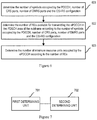
- In a long term evolution (LTE) Rel-8/9/10 system, physical downlink control channel (PDCCH) is transmitted in each subframe, as shown in
Figure 1 . It occupies first N orthogonal frequency division multiplexing (OFDM) symbols of a subframe, wherein N may be 1, 2, 3 or 4. - In the LTE Rel-8/9/10 system, a control area used for transmitting the PDCCH consists of logical control channel elements (CCEs), wherein one CCE consists of 9 RE groups (REG). One REG consists of 4 resource elements (REs) which are the same in the time domain and are adjacent in the frequency domain. The REs constituting the REG do not include those used for transmitting common reference signals. Detailed definition of the REG is as shown in
Figure 2 . - Downlink control information (DCI) is also transmitted taking CCE as a transmission unit. For the DCI of a user equipment (UE, i.e., user terminal), it may be transmitted on M logically continuous CCEs. In the LTE system, the value of M may be 1, 2, 4 or 8, which is referred to as aggregation level. The UE performs a blind detection in the control area, determines whether there is PDCCH transmitted for the UE. The blind detection is to perform decoding attempts with respect to different DCI formats and CCE aggregation levels using radio network temporary identity (RNTI) of the UE. If the decoding is correct, the DCI with respect to the UE is received. The LTE UE needs to perform the blind detection in the control area of each downlink subframe in a discontinuous reception (DRX) status and searches for the PDCCH.
-
Figures 3a ,3b and 3c show configurations of channel state information-reference signal (CSI-RS) in an LTE Rel-10 system, whereinFigure 3a shows the configuration for 2 ports,Figure 3b shows the configuration for 4 ports, andFigure 3c shows multiplexing manner for 8 ports. The number of CSI-RS ports and their resource positions are configured independently for each user. Thus, for different users, different resource positions may be occupied. Each user may further be configured with zero-power CSI-RS resources which are configured following the configuration of 4 CSI-RS ports. No signal is transmitted on the zero-power CSI-RS resources. The zero-power CSI-RS is configured via radio resource control (RRC) signaling. If a 4 port CSI-RS pattern is configured to be zero-power CSI-RS, it indicates that the user regards that no physical downlink shared channel (PDSCH) data is transmitted on these REs. - It can be seen from
Figures 3a ,3b and 3c that, in one physical resource block (PRB) pair, the size of resources available for transmitting control channel varies with the CSI-RS configuration. - In LTE Rel-11 edition, enhanced PDCCH (ePDCCH) is transmitted in the PDSCH area (i.e., data area). For different CSI-RS configurations, the number of available REs in the PDSCH area may be different, i.e., the number of REs used for transmitting the ePDCCH is different, which has a relatively large impact to demodulation performance of control signaling.
- At present, with respect to the LTE Rel-11 edition, there is no transmission solution for the ePDCCH. The 3GPP document R1-120112, CATT, Considerations on multiplexing of different DCIs, published 31 January 2012, discloses resource allocation for the ePDCCH. HTC "Discussion on Multiplexing of Different DCI messages", 3GPP, DRAFT; R1-120268, 3RD GENERATION PARTNERSHIP PROJECT (3GPP), MOBILE COMPETENCE CENTER; 650, ROUTE DES LUCIOLES; F-06921 SOPHIA-ANTIPOLIS CEDEX; FRANCE, vol. RAN WG1, no. Dresden, Germany; 1 February 2012, XP050563178 discloses calculation of suitable eCCE size with different system configurations.
- The present invention provides a method for determining enhanced physical downlink control channel, ePDCCH, resources according to
claim 1 and a corresponding apparatus according toclaim 3. In the following, embodiments not falling within the scope of the appended claims are to be interpreted as examples useful for understanding the invention. -
-
Figure 1 shows multiplexing of control area and data area in a downlink subframe in a conventional LTE Rel-8/9/10 system. -
Figure 2 shows REGs in the conventional LTE Rel-8/9/10 system. -
Figures 3a ,3b and 3c show CSI-RS configurations in a conventional LTE Rel-10 system. -
Figures 4a, 4b and4c respectively show number and distribution of eCCEs in a PRB pair in an LTE Rel-11 system according to an example of the present disclosure. -
Figures 5a ,5b and 5c respectively show division of resource blocks in a PRB pair according to an example of the present disclosure. -
Figure 6 shows an example of determining number of ePDCCH resource units according to the present disclosure. -
Figure 7 shows an example of an apparatus for determining number of ePDCCH resource units according to the present disclosure. - Hereinafter the present disclosure is described with reference to accompanying drawings and examples.
- In examples of the present disclosure, number of symbols occupied by PDCCH, number of CRS ports and number of DMRS ports and CSI-RS configuration in a subframe are determined first. Then, according to the number of symbols occupied by the PDCCH, the number of CRS ports, the number of DMRS ports and the CSI-RS configuration, it is possible to determine the resources for transmitting ePDCCH in the PDSCH area of the subframe.
- In one example, for an LTE Rel-11 system, size of a minimum resource unit of ePDCCH (i.e., the number of REs included) is defined first. Then, according to the number of REs available for transmitting the ePDCCH in the PDSCH area in a subframe under each configuration, it is possible to obtain the number of resource units occupied by the ePDCCH in the subframe under the configuration.
- Hereinafter, eCCE, eREG and resource block which is obtained through average division of a PRB pair are taken as exemplary minimum resource units of the ePDCCH to describe the present disclosure.
- Example 1 describes a method for determining number of ePDCCH resource units when the eCCE is taken as the minimum resource unit of the ePDCCH.
- When the eCCE is taken as the minimum resource unit of the ePDCCH, the size of the eCCE may be defined approximately the same as the CCE in the LTE Rel-8/9/10 system. The size of the eCCE in the subframe may change under different configurations, which is mainly determined by the configuration of the subframe (the number of available REs in the PDSCH area of the subframe may vary under different configurations). In the subframes with the same configuration, the sizes of the eCCEs may be the same or have slight difference, which is mainly determined by a mapping manner from the eCCE to the REs. In particular, one PRB pair includes an integer number of eCCEs. The number is denoted by M. The value of M may be 2, 3 or 4. In the case that the size of the eCCE is defined, the value of M is determined by the number of REs available for the ePDCCH in one PRB pair. For example, it is defined that one eCCE includes approximately 30 REs. Thus, if the number of REs available for the ePDCCH in one PRB pair is less than 90, the PRB pair includes 2 eCCEs. If the number of REs available for the ePDCCH in one PRB pair is between 90 and 120, the PRB pair includes 3 eCCEs. If the number of REs available for the ePDCCH in one PRB pair is between 120 and 150, the PRB pair includes 4 eCCEs, and so on.
- For the PRB pairs under various CSI-RS configurations,
Figures 4a, 4b and4c respectively show the size of the eCCE defined by the example of the present disclosure, the number and the distribution of the eCCEs included in the PRB pair under various CSI-RS configurations. - As shown in
Figure 4a , one PRB pair occupies 14 OFDM symbols (symbols 0∼13) in the time domain, and occupies 12 subcarriers in the frequency domain (subcarriers 0∼11), wherein each small rectangle represents an RE. The first three symbols (symbols 0∼2) in the PRB pair are occupied by "conventional PDCCH (i.e., PDCCH in LTE Rel-8/9/10 system)", the data area occupies other symbols (symbols 3∼13). In this PRB pair, the rectangles filled by slanted lines represent REs occupied by four CRS (cell reference signal, i.e., common reference signal) ports. The rectangles filled with horizontal lines represent REs occupied by Demodulation reference signal (DMRS). The rectangles filled with vertical lines represent REs occupied by CSI-RS. Thus, 52 RE resources are remained in the data area (e.g., the REs denoted by the black rectangles). If it is defined that one eCCE includes approximately 30 REs, in the case that the number of REs available for the ePDCCH in one PRB pair is less than 90, the PRB pair includes 2 eCCEs. Therefore, the PRB pair as shown inFigure 4a includes two eCCEs, each of which includes 26 REs. For simplicity, the available REs are divided into two parts, an upper part and a lower part. The 26 REs in the upper part form one eCCE, and the 26 REs in the lower part form another eCCE. The above mapping from the eCCE to the REs is just an example. The mapping may be implemented differently and is not restricted in the present disclosure. - As shown in
Figure 4b , the first two symbols in the PRB pair are occupied by the "conventional PDCCH". The rectangles filled with slanted lines represent the REs occupied by 2 CRS ports. The rectangles filled with horizontal lines represent REs occupied by the DMRS. The rectangles filled with vertical lines represent REs (6 REs in all) occupied by the CSI-RS. Thus, 102 RE resources are remained in the data area. If it is defined that one eCCE includes approximately 30 REs, and in the case that the number of REs available for the ePDCCH in one PRB pair is between 90 and 120, the PRB pair includes 3 eCCEs. Therefore, the PRB pair as shown inFigure 4b includes 3 eCCEs, each of which includes 34 REs. The mapping from the eCCE to the REs inFigure 4b is as follows: the available REs in the data area are divided into three parts: an upper part, a middle part and a lower part. The REs in each part form one eCCE. In particular, as shown inFigure 4b , each of the upper two eCCE includes 35 REs and the lowest eCCE includes 32 REs. The mapping may be implemented via other manners in which the number of REs included in each eCCE may be different from the above example. The number of the REs is related to the adopted mapping manner. - Similarly, as shown in
Figure 4c , the number of REs available for the ePDCCH in the PRB pair is 90. If it is defined that one eCCE includes no more than 30 REs, in the case that the number of available REs for the ePDCCH in one PRB pair is 90 ∼ 120, the PRB pair shown inFigure 4c includes 3 eCCEs. According to a mapping similar asFigure 4b , one eCCE includes approximately 30 REs. - Example 2 describes a method for determining the number of ePDCCH resource units when eREG is taken as the minimum resource unit of the ePDCCH.
- If the eREG is taken as the minimum resource unit of the ePDCCH, it is possible to define the size of the eREG to be the same as the REG in the LTE Rel-8/9/10 system (includes 4 REs) or define the size of the eREG to other values. The number of REs included in the eREG is fixed. When different mapping manners (mapping from eREG to REs) are adopted, the number of eREGs in one PRB pair under the same configuration may change.
- As shown in
Figure 4a , the data area includes 52 REs available for the ePDCCH. If it is defined that one eREG includes 4 REs and the mapping manner is 4 REs adjacent in the frequency domain constitute a group, there are 13 eREGs altogether. For the PRB pair as shown inFigure 4b , the data area includes 102 REs available for the ePDCCH, if the same mapping manner is adopted, there are 23 eREGs altogether (there are some REs cannot be used for ePDCCH transmission). For the PRB pair as shown inFigure 4b , in case of slanted mapping manner (e.g.,subcarrier 4 ofsymbol 2,subcarrier 5 ofsymbol 3,subcarrier 6 ofsymbol 4, andsubcarrier 7 ofsymbol 5 constitute one group), the number of eREGs in one PRB pair may be different from that of the above mapping manner. For the PRB pair as shown inFigure 4c , if an interleaving mapping manner is adopted, the number of REs cannot be used for ePDCCH transmission may be smaller than that of the frequency-domain continuous mapping manner or the slanted mapping manner. - It can be seen from the above that, for different situations of the number of PDCCH symbols (refers to "conventional PDCCH"), the number of CRS ports, the number of DMRS ports and the CSI-RS configuration, the number of REs available for transmitting the ePDCCH in the PDSCH area may change. The present disclosure may define in standards the resource mapping manner, the size of the minimum resource unit of the ePDCCH, and define, under the defined resource mapping manner, the number of the minimum resource units (eCCEs or eREGs) of the ePDCCH for each configuration of the number of PDCCH symbols, the number of CRS ports, the number of DMRS ports and the CSI-RS configuration. In other words, the present disclosure may define in the standards the resource mapping manner and the size of the minimum resource unit of the ePDCCH, and may define under the defined resource mapping manner, the number of the minimum resource units (eCCEs or eREGs) of the ePDCCH for each number of REs available for transmitting the ePDCCH (the number of REs is determined by the number of PDCCH symbols, number of CRS ports, number of DMRS ports and the CSI-RS configuration). For example, the number of REs available for transmitting the E-PDCCH in one PRB pair is N, the number of eCCEs is M. If a<N ≤b, M=2; if b<N≤c, M=3; if c<N≤d, M=4, wherein a=60, b=90, c=120 and d=150. The values may be defined in the standards. Thus, UE is not required to be additionally notified about the values. The values may also be notified to eNB or UE by system via signaling.
- Example 3 describes a method for determining the number of ePDCCH resource units if a resource block obtained by average division is taken as the minimum resource unit of the ePDCCH.
- Besides 24 REs occupied by the DMRS, there are 144 REs in one PRB pair. The 144 REs in the PRB pair may be averagely divided into 8, 12, 16, 24 or 36 resource blocks. In the present disclosure, such a resource block is taken as the minimum resource block for the ePDCCH to allocate resources for the ePDCCH.
- In a situation as shown in
Figure 5a , first three symbols are occupied by the PDCCH. There are 4 CRS ports (as shown by rectangles filled with slanted lines). The REs occupied by the DMRS are represented by the rectangles filled with horizontal lines. The REs occupied by the CSI-RS are represented by the rectangles filled with vertical lines. In a situation as shown inFigure 5b , the first symbol is occupied by the PDCCH. There are 2 CRS ports (as shown by rectangles filled with slanted lines). The REs occupied by the DMRS are represented by the rectangles filled with horizontal lines. The REs occupied by the CSI-RS are represented by the rectangles filled with vertical lines. One PRB pair as shown inFigures 5a and5b is divided into 8 resource blocks. - Although
Figures 5a and5b divide one PRB pair into the same number of resource blocks, the REs which are actually available for transmitting the ePDCCH are shown by the white rectangles, the sizes (i.e., numbers) of these REs are different in the two Figures. - In example 3, a requirement on the size of the resource block (i.e., the number of REs in one resource block) for transmitting the ePDCCH may be defined in advance. Thus, after the number of REs available for transmitting the ePDCCH in the PDSCH area of the subframe is determined according to the number of symbols occupied by the PDCCH, the number of CRS ports, the number of DMRS ports and the CSI-RS configuration, the division manner of the PRB pair, i.e., the number of resource blocks occupied by the ePDCCH in the subframe may be determined according to the size of the resource block for transmitting the ePDCCH defined in advance.
- For example, it is defined that the resource block used for transmitting the ePDCCH includes approximately 12 REs, at least 10 REs. Thus, for the situation as shown in
Figure 5a , if the PRB pair is divided into 8 resource blocks, there may be some resource blocks which include less than 10 resource blocks, which does not meet the requirement. Thus, it is possible to divide the PRB pair into 4 resource blocks as shown inFigure 5c . For the situation as shown inFigure 5b , if the PRB pair is divided into 8 resource blocks, the number of REs included in each resource block meets the requirement. Therefore, the PRB pair may be divided into 8 resource blocks. - It should be noted that, the above just shows examples of the division of the resource blocks. Those skilled in the art would get variations according to the above principle to divide the resource block.
- In accordance with the above examples,
Figure 6 shows an example of an eNB allocating for UE resources for transmitting the ePDCCH according to the present disclosure. - As shown in
Figure 6 , an evolution NodeB (eNB) side or a UE side needs to determine the number of symbols occupied by the PDCCH, number of CRS ports, number of DMRS ports and the CSI-RS configuration (block 601), and then determines the number of REs available for transmitting the ePDCCH in the PDSCH area of the subframe according to the above information (block 602). Thus, the number of minimum resource units of the ePDCCH may be determined according to the number of REs and the content defined by the standards as described above (block 603). For example, the number of eREGs available for transmitting the ePDCCH may be obtained through a rounding operation to a quotient of the number of REs and the size of the eREG. - When transmitting the ePDCCH, the eNB side may firstly determine the number of eCCEs/eREGs of the ePDCCH according to the above manner, and then transmits the ePDCCH according to a conventional manner.
- When receiving and demodulating the ePDCCH, the UE side may determine the number of PDCCH symbols, the number of CRS ports, the numbers of non-zero power and zero-power CSI-RS and the number of DMRS ports according to a conventional manner. Then, after the number of RE resources occupied by the above channel and signals are subtracted, the UE side may determine the number of REs available for transmitting the ePDCCH. According to the definition of the standards, the UE side may determine the number of eCCEs/eREGs and then demodulate the ePDCCH according to a conventional manner.
- In view of the above, since the number of resource units (eCCEs or eREGs or resource blocks) available for transmitting the ePDCCH in one PRB pair is relevant to the CSI-RS configuration and the number may vary a lot, the number of eCCEs or eREGs or resource blocks in the PRB pair should change along with the configuration. If the number of the eCCEs or eREGs or resource blocks is fixed, there may be waste of resources. The present disclosure avoids this problem.
- In accordance with the above examples, an example of the present disclosure provides an apparatus for determining the number of ePDCCH resource units. The apparatus may be configured in a network device side, e.g., in an eNB. The apparatus may also be configured in UE.
- As shown in
Figure 7 which shows an example of the apparatus for determining the number of ePDCCH resource units according to the present disclosure, the apparatus includes: - a first determining
unit 701, to determine number of symbols occupied by PDCCH, number of CRS ports, number of DMRS ports and a CSI-RS configuration in a subframe; and - a second determining
unit 702, to determine resources available for transmitting ePDCCH in a PDSCH area of the subframe according to the number of symbols occupied by the PDCCH, the number of CRS ports, the number of DMRS ports and the CSI-RS configuration. - The apparatus may further include a third determining unit 703;
- The second determining
unit 702 further determines the number of REs available for transmitting the ePDCCH in the PDSCH area of the subframe according to the number of symbols occupied by the PDCCH, the number of CRS ports, the number of DMRS ports and the CSI-RS configuration; and
the third determining unit 703 is to determines the number of resource units occupied by the ePDCCH in the subframe according to the number of REs. - For the number of REs available for transmitting the ePDCCH in the subframe under each configuration, system information includes the number of resource units occupied by the ePDCCH in the subframe. Accordingly, the third determining unit 703 may determine the number of the resource units occupied by the ePDCCH in the subframe corresponding to the number of the REs according to the system information and the number of the REs.
- If the eCCE is the minimum resource block of the ePDCCH, the system information further includes the number of REs included in the eCCE with respect to each resource mapping manner. Accordingly, according to the number of REs available for transmitting the ePDCCH in the subframe under each configuration, it is possible to define the corresponding number of eCCEs (e.g., the larger the number of the REs available for transmitting the ePDCCH in the subframe, the larger the number of the eCCEs). The eCCEs in subframes under different configurations may include the same or different numbers of REs. The configuration includes the number of symbols occupied by the PDCCH, the number of CRS ports, the number of DMRS ports and the CSI-RS configuration. For different resource mapping manners, in one subframe, the number of REs in each eCCE may change or not.
The eREG may also be taken as the minimum resource unit of the ePDCCH. Under different configurations, the number of REs in the eREG does not change. The configuration includes the number of symbols occupied by the PDCCH, the number of CRS ports, the number of DMRS ports and the CSI-RS configuration. - If the resource block obtained via average division is taken as the minimum resource unit of the ePDCCH, the system information further includes the requirement on the number of REs included in the resource block. The third determining unit 703 determines, according to the system information and the determined number of REs, the resource division manner of the physical resource blocks (PRBs) in the subframe corresponding to the number of REs. The number of REs in each resource block obtained according to the determined resource division manner meets the requirement on the number of REs in the resource block defined by the system information.
- Those skilled in the art would know that the units in the apparatus of the present disclosure may be configured in the apparatus according to the description of the example, or be configured in one or more apparatuses after some modifications. The units may be combined into one unit or divided into multiple subunits.
- In view of the above description, it is clear for those skilled in the art that the present disclosure may be implemented by software and necessary universal hardware platform, or implemented by hardware. In some cases, the former implementation manner is better. Based on this, the technical solution of the present disclosure or the contribution part of the present disclosure may be implemented as software product. The software product is stored in a storage medium, including a set of instructions to enable a computer device (e.g., a personal computer, a server, or a network device, etc.) to execute the method provided by the examples of the present disclosure.
- What has been described and illustrated herein is a preferred example of the disclosure along with some of its variations. It should be noted that, for those skilled in the art many variations are possible within the scope of the disclosure, which are also within the protection scope of the present disclosure.
Claims (4)
- A method for determining enhanced physical downlink control channel, ePDCCH, resources, comprising:determining a number of symbols occupied by a physical downlink control channel, PDCCH, a number of common reference signal, CRS, ports, a number of demodulation reference signal, DMRS, ports and a channel state information-reference signal, CSI-RS, configuration in a subframe (601); anddetermining resources available for transmitting an ePDCCH in a physical downlink shared channel, PDSCH, area of the subframe according to the number of symbols occupied by the PDCCH, the number of CRS ports, the number of DMRS ports and the CSI-RS configuration (602); wherein the determining the resources available for transmitting the ePDCCH in the PDSCH area of the subframe according to the number of symbols occupied by the PDCCH, the number of CRS ports, the number of DMRS ports and the CSI-RS configuration comprises:determining a number of resource elements, REs, available for transmitting the ePDCCH in the PDSCH area of the subframe according to the number of symbols occupied by the PDCCH, the number of CRS ports, the number of DMRS ports and the CSI-RS configuration of the subframe; anddetermining a number of resource units occupied by the ePDCCH in the subframe according to the number of REs of the subframe (603);wherein for the number of REs available for transmitting the ePDCCH in the subframe under each configuration, the number of resource units occupied by the ePDCCH in the subframe is defined in system information;the determining the number of resource units occupied by the ePDCCH in the subframe according to the number of REs comprises:determining the number of resource units occupied by the ePDCCH in the subframe corresponding to the number of REs according to the system information and the number of REs;wherein an enhanced control channel element, eCCE, is the resource unit of the ePDCCH, for the number of REs available for transmitting the ePDCCH in the subframe under each configuration, defining the number of resource units occupied by the ePDCCH in the subframe comprises:according to the number of REs available for transmitting the ePDCCH in the subframe under each configuration, defining the number of eCCEs, characterized in that if the number of REs available for the ePDCCH in one PRB pair is less than 90, the PRB pair includes exactly 2 eCCEs.
- The method of claim 1, wherein for subframes with different configurations, the eCCE comprises the same or different number of REs, wherein the configuration comprises the number of symbols occupied by the PDCCH, the number of CRS ports, the number of DMRS ports and the CSI-RS configuration;
wherein in the subframe, the eCCE comprises the same or different number of REs according to the resource mapping manner. - An apparatus for determining enhanced physical downlink control channel, ePDCCH, resources, comprising:a first determining unit (701) configured to determine number of symbols occupied by a physical downlink control channel, PDCCH, a number of common reference signal, CRS, ports, a number of demodulation reference signal, DMRS, ports and a channel state information-reference signal, CSI-RS, configuration in a subframe; anda second determining unit (702) configured to determine resources available for transmitting an ePDCCH in a physical downlink shared channel, PDSCH, area of the subframe according to the number of symbols occupied by the PDCCH, the number of CRS ports, the number of DMRS ports and the CSI-RS configuration; wherein the second determining unit (702) is further to determine a number of resource elements, REs, available for transmitting the ePDCCH in the PDSCH area of the subframe according to the number of symbols occupied by the PDCCH, the number of CRS ports, the number of DMRS ports and the CSI-RS configuration of the subframe; andthe apparatus further comprises a third determining unit (703) adapted to determine a number of resource units occupied by the ePDCCH in the subframe according to the number of REs of the subframe;wherein for the number of REs available for transmitting the ePDCCH in the subframe under each configuration, the number of resource units occupied by the ePDCCH in the subframe is defined in system information; the third determining unit is further to determine the number of resource units occupied by the ePDCCH in the subframe corresponding to the number of the REs according to the system information;wherein an enhanced control channel element, eCCE, is the resource unit of the ePDCCH, the system information further comprises the number of REs comprised in the eCCE with respect to each resource mapping manner;for the number of REs available for transmitting the ePDCCH in the subframe under each configuration, the number of eCCEs is defined, characterized in that if the number of REs available for the ePDCCH in one PRB pair is less than 90, the PRB pair includes exactly 2 eCCEs.
- The apparatus of claim 3, wherein for subframes under different configurations, the eCCE comprises the same or different number of REs; wherein the configuration comprises the number of symbols occupied by the PDCCH, the number of CRS ports, the number of DMRS ports and the CSI-RS configuration; with respect to different resource mapping manners, the eCCE comprises the same or different number of REs in one subframe.
Applications Claiming Priority (3)
| Application Number | Priority Date | Filing Date | Title |
|---|---|---|---|
| CN201210072120 | 2012-03-19 | ||
| CN201210202448.2A CN103327493B (en) | 2012-03-19 | 2012-06-19 | EPDCCH resource units quantity determines method and device |
| PCT/CN2013/072315 WO2013139211A1 (en) | 2012-03-19 | 2013-03-07 | Method and device for determining epdcch resources |
Publications (3)
| Publication Number | Publication Date |
|---|---|
| EP2830376A1 EP2830376A1 (en) | 2015-01-28 |
| EP2830376A4 EP2830376A4 (en) | 2015-03-11 |
| EP2830376B1 true EP2830376B1 (en) | 2018-04-11 |
Family
ID=49195971
Family Applications (1)
| Application Number | Title | Priority Date | Filing Date |
|---|---|---|---|
| EP13764420.9A Active EP2830376B1 (en) | 2012-03-19 | 2013-03-07 | Method and device for determining epdcch resources |
Country Status (5)
| Country | Link |
|---|---|
| US (1) | US9426799B2 (en) |
| EP (1) | EP2830376B1 (en) |
| KR (2) | KR101794785B1 (en) |
| CN (1) | CN103327493B (en) |
| WO (1) | WO2013139211A1 (en) |
Families Citing this family (12)
| Publication number | Priority date | Publication date | Assignee | Title |
|---|---|---|---|---|
| KR101703864B1 (en) * | 2010-04-29 | 2017-02-22 | 엘지전자 주식회사 | A method and a base station for transmitting control information, and a method and a user equipment for receiving control information |
| KR20150032857A (en) * | 2012-06-12 | 2015-03-30 | 엘지전자 주식회사 | Method and apparatus for receiving control information through epdcch in wireless communication system |
| CA2911048C (en) * | 2012-07-27 | 2018-01-23 | Huawei Device Co., Ltd. | Method and apparatus for transmitting control channel |
| EP2874454A1 (en) * | 2013-11-15 | 2015-05-20 | Fujitsu Limited | Reference signals in wireless communication |
| CN105264988B (en) * | 2014-01-09 | 2019-06-21 | 华为技术有限公司 | A kind of configuration method of signal resource, equipment and system |
| CN108023849A (en) * | 2016-11-04 | 2018-05-11 | 北京三星通信技术研究有限公司 | The method for reporting and device of a kind of channel condition information |
| CN114567533A (en) * | 2016-11-04 | 2022-05-31 | 北京三星通信技术研究有限公司 | Method and device for reporting channel state information |
| CN109391458B (en) * | 2017-08-11 | 2021-09-24 | 株式会社Kt | Method for multiplexing DMRS and data in new radio and apparatus therefor |
| WO2020145681A1 (en) * | 2019-01-10 | 2020-07-16 | Samsung Electronics Co., Ltd. | Method, apparatus for transmitting harq-ack information, electronic device and storage medium |
| CN113259052A (en) * | 2020-02-12 | 2021-08-13 | 夏普株式会社 | Method performed by user equipment and user equipment |
| CN115606295A (en) * | 2021-03-31 | 2023-01-13 | 苹果公司(Us) | Resource counting for reference signals |
| US20230403723A1 (en) * | 2022-06-08 | 2023-12-14 | Samsung Electronics Co., Ltd. | Reception of control signaling in presence of interference |
Family Cites Families (13)
| Publication number | Priority date | Publication date | Assignee | Title |
|---|---|---|---|---|
| KR20120018141A (en) * | 2009-06-02 | 2012-02-29 | 엘지전자 주식회사 | Method and apparatus for transmitting and receiving control information in multi-carrier system |
| US8804586B2 (en) | 2010-01-11 | 2014-08-12 | Blackberry Limited | Control channel interference management and extended PDCCH for heterogeneous network |
| KR101684867B1 (en) * | 2010-04-07 | 2016-12-09 | 삼성전자주식회사 | Transmission and reception method of control information to exploit the spatial multiplexing gain |
| CN102271402B (en) | 2010-06-03 | 2015-06-03 | 中兴通讯股份有限公司 | Method and device for mapping resource in downlink control channel |
| CN102316060A (en) * | 2010-06-30 | 2012-01-11 | 华为技术有限公司 | Method and device for determining quantity of symbols occupied by physical downlink control channel |
| CN102378373A (en) * | 2010-08-17 | 2012-03-14 | 电信科学技术研究院 | Control channel transmission and resource determination method, base station and terminal |
| CN102724757B (en) * | 2011-03-30 | 2017-11-07 | 中兴通讯股份有限公司 | A kind of control channel information processing method and system |
| US9084238B2 (en) * | 2011-09-12 | 2015-07-14 | Blackberry Limited | Searching space and operation for enhanced PDCCH in LTE systems |
| CN102316595B (en) * | 2011-09-30 | 2017-04-12 | 中兴通讯股份有限公司 | Resource determination method and device for physical uplink control channel (PUCCH) of large-band-width system |
| CN103650631A (en) * | 2011-09-30 | 2014-03-19 | 富士通株式会社 | Method and device for notifying physical downlink shared channel starting symbol |
| US9467991B2 (en) * | 2011-11-23 | 2016-10-11 | Lg Electronics Inc. | Methods and apparatuses for transmitting and receiving downlink control channel in wireless communication system |
| EP2784959B1 (en) * | 2011-11-23 | 2017-10-11 | LG Electronics Inc. | Determination of epdcch starting symbol for tdd subframe 6 |
| US9215058B2 (en) * | 2012-03-06 | 2015-12-15 | Blackberry Limited | Enhanced PHICH transmission for LTE-advanced |
-
2012
- 2012-06-19 CN CN201210202448.2A patent/CN103327493B/en active Active
-
2013
- 2013-03-07 KR KR1020167016458A patent/KR101794785B1/en active IP Right Grant
- 2013-03-07 WO PCT/CN2013/072315 patent/WO2013139211A1/en active Application Filing
- 2013-03-07 KR KR20147028360A patent/KR20140140072A/en active Application Filing
- 2013-03-07 EP EP13764420.9A patent/EP2830376B1/en active Active
- 2013-03-07 US US14/383,319 patent/US9426799B2/en active Active
Non-Patent Citations (2)
| Title |
|---|
| SAMSUNG: "Multiplexing of Multiple E-PDCCHs for Distributed and Localized", 3GPP DRAFT; R1-120191, 3RD GENERATION PARTNERSHIP PROJECT (3GPP), MOBILE COMPETENCE CENTRE ; 650, ROUTE DES LUCIOLES ; F-06921 SOPHIA-ANTIPOLIS CEDEX ; FRANCE, vol. RAN WG1, no. Dresden, Germany; 20120206 - 20120210, 31 January 2012 (2012-01-31), XP050562756 * |
| ZTE: "Type II relay for DL cooperative retransmission", 3GPP DRAFT; R1-091711 TYPE II RELAY FOR DL COOPERATIVE RETRANSMISSION, 3RD GENERATION PARTNERSHIP PROJECT (3GPP), MOBILE COMPETENCE CENTRE ; 650, ROUTE DES LUCIOLES ; F-06921 SOPHIA-ANTIPOLIS CEDEX ; FRANCE, no. San Francisco, USA; 20090428, 28 April 2009 (2009-04-28), XP050339246 * |
Also Published As
| Publication number | Publication date |
|---|---|
| CN103327493B (en) | 2016-12-21 |
| EP2830376A4 (en) | 2015-03-11 |
| CN103327493A (en) | 2013-09-25 |
| KR101794785B1 (en) | 2017-11-07 |
| KR20160075862A (en) | 2016-06-29 |
| US20150016386A1 (en) | 2015-01-15 |
| KR20140140072A (en) | 2014-12-08 |
| WO2013139211A1 (en) | 2013-09-26 |
| US9426799B2 (en) | 2016-08-23 |
| EP2830376A1 (en) | 2015-01-28 |
Similar Documents
| Publication | Publication Date | Title |
|---|---|---|
| EP2830376B1 (en) | Method and device for determining epdcch resources | |
| EP2843986B1 (en) | Method and device for e-pdcch transmission and blind detection | |
| EP3934301B1 (en) | Method and apparatus for transmitting information on enhanced physical downlink control channel | |
| KR102033442B1 (en) | Method and apparatus for blindly detecting a common search space and a ue specific search space | |
| US9204439B2 (en) | Search space arrangement for control channel | |
| US9930649B2 (en) | Method and apparatus for transmitting downlink control information | |
| EP2820871B1 (en) | Systems and methods for ue-specific search space and epdcch scrambling | |
| EP2941077B1 (en) | Pdsch transmission method and device | |
| EP2660994B1 (en) | Method and device for allocating reference resource | |
| EP2793525B1 (en) | Control channel mapping method, base station and user equipment | |
| US9699772B2 (en) | Method, system and apparatus for information transmission | |
| US20140286297A1 (en) | Method and apparatus for transmitting downlink control information | |
| US9641300B2 (en) | Method for transmitting and receiving control channel, base station, and user equipment | |
| US10492188B2 (en) | Method of and apparatus for pre-coded physical downlink control channel reference signal and blind decoding | |
| WO2013007144A1 (en) | Method, device and system for transmitting and receiving data | |
| EP2858439A1 (en) | Control information transmission method, base station, and user equipment | |
| EP2830249B1 (en) | Control signaling demodulation method and terminal | |
| US9692574B2 (en) | Methods and devices for detecting control signaling and implementing control signaling detection | |
| EP2765802B1 (en) | Control channel transmission method and apparatus | |
| US20160316456A1 (en) | Radio Access Node, Wireless Device and Methods Performed Therein | |
| EP3389213B1 (en) | Method and device for receiving enhanced physical downlink control channel e-pdcch |
Legal Events
| Date | Code | Title | Description |
|---|---|---|---|
| PUAI | Public reference made under article 153(3) epc to a published international application that has entered the european phase |
Free format text: ORIGINAL CODE: 0009012 |
|
| 17P | Request for examination filed |
Effective date: 20141001 |
|
| AK | Designated contracting states |
Kind code of ref document: A1 Designated state(s): AL AT BE BG CH CY CZ DE DK EE ES FI FR GB GR HR HU IE IS IT LI LT LU LV MC MK MT NL NO PL PT RO RS SE SI SK SM TR |
|
| AX | Request for extension of the european patent |
Extension state: BA ME |
|
| A4 | Supplementary search report drawn up and despatched |
Effective date: 20150206 |
|
| RIC1 | Information provided on ipc code assigned before grant |
Ipc: H04L 5/00 20060101ALI20150202BHEP Ipc: H04W 72/04 20090101AFI20150202BHEP |
|
| DAX | Request for extension of the european patent (deleted) | ||
| 17Q | First examination report despatched |
Effective date: 20151208 |
|
| STAA | Information on the status of an ep patent application or granted ep patent |
Free format text: STATUS: EXAMINATION IS IN PROGRESS |
|
| REG | Reference to a national code |
Ref country code: DE Ref legal event code: R079 Ref document number: 602013035780 Country of ref document: DE Free format text: PREVIOUS MAIN CLASS: H04W0072040000 Ipc: H04L0005000000 |
|
| GRAP | Despatch of communication of intention to grant a patent |
Free format text: ORIGINAL CODE: EPIDOSNIGR1 |
|
| STAA | Information on the status of an ep patent application or granted ep patent |
Free format text: STATUS: GRANT OF PATENT IS INTENDED |
|
| INTG | Intention to grant announced |
Effective date: 20171106 |
|
| RIC1 | Information provided on ipc code assigned before grant |
Ipc: H04L 5/00 20060101AFI20171020BHEP |
|
| GRAS | Grant fee paid |
Free format text: ORIGINAL CODE: EPIDOSNIGR3 |
|
| GRAA | (expected) grant |
Free format text: ORIGINAL CODE: 0009210 |
|
| STAA | Information on the status of an ep patent application or granted ep patent |
Free format text: STATUS: THE PATENT HAS BEEN GRANTED |
|
| AK | Designated contracting states |
Kind code of ref document: B1 Designated state(s): AL AT BE BG CH CY CZ DE DK EE ES FI FR GB GR HR HU IE IS IT LI LT LU LV MC MK MT NL NO PL PT RO RS SE SI SK SM TR |
|
| REG | Reference to a national code |
Ref country code: GB Ref legal event code: FG4D |
|
| REG | Reference to a national code |
Ref country code: CH Ref legal event code: EP |
|
| REG | Reference to a national code |
Ref country code: AT Ref legal event code: REF Ref document number: 989106 Country of ref document: AT Kind code of ref document: T Effective date: 20180415 |
|
| REG | Reference to a national code |
Ref country code: IE Ref legal event code: FG4D |
|
| REG | Reference to a national code |
Ref country code: DE Ref legal event code: R096 Ref document number: 602013035780 Country of ref document: DE |
|
| REG | Reference to a national code |
Ref country code: NL Ref legal event code: MP Effective date: 20180411 |
|
| REG | Reference to a national code |
Ref country code: LT Ref legal event code: MG4D |
|
| PG25 | Lapsed in a contracting state [announced via postgrant information from national office to epo] |
Ref country code: NL Free format text: LAPSE BECAUSE OF FAILURE TO SUBMIT A TRANSLATION OF THE DESCRIPTION OR TO PAY THE FEE WITHIN THE PRESCRIBED TIME-LIMIT Effective date: 20180411 |
|
| PG25 | Lapsed in a contracting state [announced via postgrant information from national office to epo] |
Ref country code: FI Free format text: LAPSE BECAUSE OF FAILURE TO SUBMIT A TRANSLATION OF THE DESCRIPTION OR TO PAY THE FEE WITHIN THE PRESCRIBED TIME-LIMIT Effective date: 20180411 Ref country code: AL Free format text: LAPSE BECAUSE OF FAILURE TO SUBMIT A TRANSLATION OF THE DESCRIPTION OR TO PAY THE FEE WITHIN THE PRESCRIBED TIME-LIMIT Effective date: 20180411 Ref country code: SE Free format text: LAPSE BECAUSE OF FAILURE TO SUBMIT A TRANSLATION OF THE DESCRIPTION OR TO PAY THE FEE WITHIN THE PRESCRIBED TIME-LIMIT Effective date: 20180411 Ref country code: NO Free format text: LAPSE BECAUSE OF FAILURE TO SUBMIT A TRANSLATION OF THE DESCRIPTION OR TO PAY THE FEE WITHIN THE PRESCRIBED TIME-LIMIT Effective date: 20180711 Ref country code: LT Free format text: LAPSE BECAUSE OF FAILURE TO SUBMIT A TRANSLATION OF THE DESCRIPTION OR TO PAY THE FEE WITHIN THE PRESCRIBED TIME-LIMIT Effective date: 20180411 Ref country code: PL Free format text: LAPSE BECAUSE OF FAILURE TO SUBMIT A TRANSLATION OF THE DESCRIPTION OR TO PAY THE FEE WITHIN THE PRESCRIBED TIME-LIMIT Effective date: 20180411 Ref country code: BG Free format text: LAPSE BECAUSE OF FAILURE TO SUBMIT A TRANSLATION OF THE DESCRIPTION OR TO PAY THE FEE WITHIN THE PRESCRIBED TIME-LIMIT Effective date: 20180711 Ref country code: ES Free format text: LAPSE BECAUSE OF FAILURE TO SUBMIT A TRANSLATION OF THE DESCRIPTION OR TO PAY THE FEE WITHIN THE PRESCRIBED TIME-LIMIT Effective date: 20180411 |
|
| PG25 | Lapsed in a contracting state [announced via postgrant information from national office to epo] |
Ref country code: HR Free format text: LAPSE BECAUSE OF FAILURE TO SUBMIT A TRANSLATION OF THE DESCRIPTION OR TO PAY THE FEE WITHIN THE PRESCRIBED TIME-LIMIT Effective date: 20180411 Ref country code: RS Free format text: LAPSE BECAUSE OF FAILURE TO SUBMIT A TRANSLATION OF THE DESCRIPTION OR TO PAY THE FEE WITHIN THE PRESCRIBED TIME-LIMIT Effective date: 20180411 Ref country code: GR Free format text: LAPSE BECAUSE OF FAILURE TO SUBMIT A TRANSLATION OF THE DESCRIPTION OR TO PAY THE FEE WITHIN THE PRESCRIBED TIME-LIMIT Effective date: 20180712 Ref country code: LV Free format text: LAPSE BECAUSE OF FAILURE TO SUBMIT A TRANSLATION OF THE DESCRIPTION OR TO PAY THE FEE WITHIN THE PRESCRIBED TIME-LIMIT Effective date: 20180411 |
|
| REG | Reference to a national code |
Ref country code: AT Ref legal event code: MK05 Ref document number: 989106 Country of ref document: AT Kind code of ref document: T Effective date: 20180411 |
|
| PG25 | Lapsed in a contracting state [announced via postgrant information from national office to epo] |
Ref country code: PT Free format text: LAPSE BECAUSE OF FAILURE TO SUBMIT A TRANSLATION OF THE DESCRIPTION OR TO PAY THE FEE WITHIN THE PRESCRIBED TIME-LIMIT Effective date: 20180813 |
|
| REG | Reference to a national code |
Ref country code: DE Ref legal event code: R097 Ref document number: 602013035780 Country of ref document: DE |
|
| PG25 | Lapsed in a contracting state [announced via postgrant information from national office to epo] |
Ref country code: SK Free format text: LAPSE BECAUSE OF FAILURE TO SUBMIT A TRANSLATION OF THE DESCRIPTION OR TO PAY THE FEE WITHIN THE PRESCRIBED TIME-LIMIT Effective date: 20180411 Ref country code: CZ Free format text: LAPSE BECAUSE OF FAILURE TO SUBMIT A TRANSLATION OF THE DESCRIPTION OR TO PAY THE FEE WITHIN THE PRESCRIBED TIME-LIMIT Effective date: 20180411 Ref country code: RO Free format text: LAPSE BECAUSE OF FAILURE TO SUBMIT A TRANSLATION OF THE DESCRIPTION OR TO PAY THE FEE WITHIN THE PRESCRIBED TIME-LIMIT Effective date: 20180411 Ref country code: EE Free format text: LAPSE BECAUSE OF FAILURE TO SUBMIT A TRANSLATION OF THE DESCRIPTION OR TO PAY THE FEE WITHIN THE PRESCRIBED TIME-LIMIT Effective date: 20180411 Ref country code: AT Free format text: LAPSE BECAUSE OF FAILURE TO SUBMIT A TRANSLATION OF THE DESCRIPTION OR TO PAY THE FEE WITHIN THE PRESCRIBED TIME-LIMIT Effective date: 20180411 Ref country code: DK Free format text: LAPSE BECAUSE OF FAILURE TO SUBMIT A TRANSLATION OF THE DESCRIPTION OR TO PAY THE FEE WITHIN THE PRESCRIBED TIME-LIMIT Effective date: 20180411 |
|
| PLBE | No opposition filed within time limit |
Free format text: ORIGINAL CODE: 0009261 |
|
| STAA | Information on the status of an ep patent application or granted ep patent |
Free format text: STATUS: NO OPPOSITION FILED WITHIN TIME LIMIT |
|
| PG25 | Lapsed in a contracting state [announced via postgrant information from national office to epo] |
Ref country code: IT Free format text: LAPSE BECAUSE OF FAILURE TO SUBMIT A TRANSLATION OF THE DESCRIPTION OR TO PAY THE FEE WITHIN THE PRESCRIBED TIME-LIMIT Effective date: 20180411 Ref country code: SM Free format text: LAPSE BECAUSE OF FAILURE TO SUBMIT A TRANSLATION OF THE DESCRIPTION OR TO PAY THE FEE WITHIN THE PRESCRIBED TIME-LIMIT Effective date: 20180411 |
|
| 26N | No opposition filed |
Effective date: 20190114 |
|
| PG25 | Lapsed in a contracting state [announced via postgrant information from national office to epo] |
Ref country code: SI Free format text: LAPSE BECAUSE OF FAILURE TO SUBMIT A TRANSLATION OF THE DESCRIPTION OR TO PAY THE FEE WITHIN THE PRESCRIBED TIME-LIMIT Effective date: 20180411 |
|
| PG25 | Lapsed in a contracting state [announced via postgrant information from national office to epo] |
Ref country code: MC Free format text: LAPSE BECAUSE OF FAILURE TO SUBMIT A TRANSLATION OF THE DESCRIPTION OR TO PAY THE FEE WITHIN THE PRESCRIBED TIME-LIMIT Effective date: 20180411 |
|
| REG | Reference to a national code |
Ref country code: CH Ref legal event code: PL |
|
| PG25 | Lapsed in a contracting state [announced via postgrant information from national office to epo] |
Ref country code: LU Free format text: LAPSE BECAUSE OF NON-PAYMENT OF DUE FEES Effective date: 20190307 |
|
| REG | Reference to a national code |
Ref country code: BE Ref legal event code: MM Effective date: 20190331 |
|
| PG25 | Lapsed in a contracting state [announced via postgrant information from national office to epo] |
Ref country code: LI Free format text: LAPSE BECAUSE OF NON-PAYMENT OF DUE FEES Effective date: 20190331 Ref country code: CH Free format text: LAPSE BECAUSE OF NON-PAYMENT OF DUE FEES Effective date: 20190331 Ref country code: IE Free format text: LAPSE BECAUSE OF NON-PAYMENT OF DUE FEES Effective date: 20190307 |
|
| PG25 | Lapsed in a contracting state [announced via postgrant information from national office to epo] |
Ref country code: BE Free format text: LAPSE BECAUSE OF NON-PAYMENT OF DUE FEES Effective date: 20190331 |
|
| PG25 | Lapsed in a contracting state [announced via postgrant information from national office to epo] |
Ref country code: TR Free format text: LAPSE BECAUSE OF FAILURE TO SUBMIT A TRANSLATION OF THE DESCRIPTION OR TO PAY THE FEE WITHIN THE PRESCRIBED TIME-LIMIT Effective date: 20180411 |
|
| PG25 | Lapsed in a contracting state [announced via postgrant information from national office to epo] |
Ref country code: MT Free format text: LAPSE BECAUSE OF NON-PAYMENT OF DUE FEES Effective date: 20190307 |
|
| PG25 | Lapsed in a contracting state [announced via postgrant information from national office to epo] |
Ref country code: CY Free format text: LAPSE BECAUSE OF FAILURE TO SUBMIT A TRANSLATION OF THE DESCRIPTION OR TO PAY THE FEE WITHIN THE PRESCRIBED TIME-LIMIT Effective date: 20180411 |
|
| PG25 | Lapsed in a contracting state [announced via postgrant information from national office to epo] |
Ref country code: IS Free format text: LAPSE BECAUSE OF FAILURE TO SUBMIT A TRANSLATION OF THE DESCRIPTION OR TO PAY THE FEE WITHIN THE PRESCRIBED TIME-LIMIT Effective date: 20180811 |
|
| PG25 | Lapsed in a contracting state [announced via postgrant information from national office to epo] |
Ref country code: HU Free format text: LAPSE BECAUSE OF FAILURE TO SUBMIT A TRANSLATION OF THE DESCRIPTION OR TO PAY THE FEE WITHIN THE PRESCRIBED TIME-LIMIT; INVALID AB INITIO Effective date: 20130307 |
|
| REG | Reference to a national code |
Ref country code: DE Ref legal event code: R081 Ref document number: 602013035780 Country of ref document: DE Owner name: DATANG MOBILE COMMUNICATIONS EQUIPMENT CO., LT, CN Free format text: FORMER OWNER: CHINA ACADEMY OF TELECOMMUNICATIONS TECHNOLOGY, BEIJING, CN |
|
| REG | Reference to a national code |
Ref country code: GB Ref legal event code: 732E Free format text: REGISTERED BETWEEN 20210729 AND 20210804 |
|
| PG25 | Lapsed in a contracting state [announced via postgrant information from national office to epo] |
Ref country code: MK Free format text: LAPSE BECAUSE OF FAILURE TO SUBMIT A TRANSLATION OF THE DESCRIPTION OR TO PAY THE FEE WITHIN THE PRESCRIBED TIME-LIMIT Effective date: 20180411 |
|
| PGFP | Annual fee paid to national office [announced via postgrant information from national office to epo] |
Ref country code: FR Payment date: 20230324 Year of fee payment: 11 |
|
| PGFP | Annual fee paid to national office [announced via postgrant information from national office to epo] |
Ref country code: GB Payment date: 20230322 Year of fee payment: 11 Ref country code: DE Payment date: 20230321 Year of fee payment: 11 |
|
| P01 | Opt-out of the competence of the unified patent court (upc) registered |
Effective date: 20230512 |