EP2830326A1 - Audio prcessor for object-dependent processing - Google Patents
Audio prcessor for object-dependent processing Download PDFInfo
- Publication number
- EP2830326A1 EP2830326A1 EP14160876.0A EP14160876A EP2830326A1 EP 2830326 A1 EP2830326 A1 EP 2830326A1 EP 14160876 A EP14160876 A EP 14160876A EP 2830326 A1 EP2830326 A1 EP 2830326A1
- Authority
- EP
- European Patent Office
- Prior art keywords
- equalizer setting
- distance
- sound
- equalizer
- loudspeaker
- Prior art date
- Legal status (The legal status is an assumption and is not a legal conclusion. Google has not performed a legal analysis and makes no representation as to the accuracy of the status listed.)
- Withdrawn
Links
Images




Classifications
-
- H—ELECTRICITY
- H04—ELECTRIC COMMUNICATION TECHNIQUE
- H04S—STEREOPHONIC SYSTEMS
- H04S1/00—Two-channel systems
- H04S1/002—Non-adaptive circuits, e.g. manually adjustable or static, for enhancing the sound image or the spatial distribution
-
- H—ELECTRICITY
- H04—ELECTRIC COMMUNICATION TECHNIQUE
- H04R—LOUDSPEAKERS, MICROPHONES, GRAMOPHONE PICK-UPS OR LIKE ACOUSTIC ELECTROMECHANICAL TRANSDUCERS; ELECTRIC HEARING AIDS; PUBLIC ADDRESS SYSTEMS
- H04R5/00—Stereophonic arrangements
- H04R5/04—Circuit arrangements, e.g. for selective connection of amplifier inputs/outputs to loudspeakers, for loudspeaker detection, or for adaptation of settings to personal preferences or hearing impairments
-
- H—ELECTRICITY
- H04—ELECTRIC COMMUNICATION TECHNIQUE
- H04R—LOUDSPEAKERS, MICROPHONES, GRAMOPHONE PICK-UPS OR LIKE ACOUSTIC ELECTROMECHANICAL TRANSDUCERS; ELECTRIC HEARING AIDS; PUBLIC ADDRESS SYSTEMS
- H04R3/00—Circuits for transducers
- H04R3/04—Circuits for transducers for correcting frequency response
-
- H—ELECTRICITY
- H04—ELECTRIC COMMUNICATION TECHNIQUE
- H04S—STEREOPHONIC SYSTEMS
- H04S7/00—Indicating arrangements; Control arrangements, e.g. balance control
- H04S7/30—Control circuits for electronic adaptation of the sound field
- H04S7/302—Electronic adaptation of stereophonic sound system to listener position or orientation
- H04S7/303—Tracking of listener position or orientation
-
- H—ELECTRICITY
- H04—ELECTRIC COMMUNICATION TECHNIQUE
- H04R—LOUDSPEAKERS, MICROPHONES, GRAMOPHONE PICK-UPS OR LIKE ACOUSTIC ELECTROMECHANICAL TRANSDUCERS; ELECTRIC HEARING AIDS; PUBLIC ADDRESS SYSTEMS
- H04R2400/00—Loudspeakers
- H04R2400/03—Transducers capable of generating both sound as well as tactile vibration, e.g. as used in cellular phones
-
- H—ELECTRICITY
- H04—ELECTRIC COMMUNICATION TECHNIQUE
- H04R—LOUDSPEAKERS, MICROPHONES, GRAMOPHONE PICK-UPS OR LIKE ACOUSTIC ELECTROMECHANICAL TRANSDUCERS; ELECTRIC HEARING AIDS; PUBLIC ADDRESS SYSTEMS
- H04R2420/00—Details of connection covered by H04R, not provided for in its groups
- H04R2420/01—Input selection or mixing for amplifiers or loudspeakers
-
- H—ELECTRICITY
- H04—ELECTRIC COMMUNICATION TECHNIQUE
- H04R—LOUDSPEAKERS, MICROPHONES, GRAMOPHONE PICK-UPS OR LIKE ACOUSTIC ELECTROMECHANICAL TRANSDUCERS; ELECTRIC HEARING AIDS; PUBLIC ADDRESS SYSTEMS
- H04R2420/00—Details of connection covered by H04R, not provided for in its groups
- H04R2420/03—Connection circuits to selectively connect loudspeakers or headphones to amplifiers
-
- H—ELECTRICITY
- H04—ELECTRIC COMMUNICATION TECHNIQUE
- H04R—LOUDSPEAKERS, MICROPHONES, GRAMOPHONE PICK-UPS OR LIKE ACOUSTIC ELECTROMECHANICAL TRANSDUCERS; ELECTRIC HEARING AIDS; PUBLIC ADDRESS SYSTEMS
- H04R2499/00—Aspects covered by H04R or H04S not otherwise provided for in their subgroups
- H04R2499/10—General applications
- H04R2499/11—Transducers incorporated or for use in hand-held devices, e.g. mobile phones, PDA's, camera's
-
- H—ELECTRICITY
- H04—ELECTRIC COMMUNICATION TECHNIQUE
- H04S—STEREOPHONIC SYSTEMS
- H04S2400/00—Details of stereophonic systems covered by H04S but not provided for in its groups
- H04S2400/03—Aspects of down-mixing multi-channel audio to configurations with lower numbers of playback channels, e.g. 7.1 -> 5.1
-
- H—ELECTRICITY
- H04—ELECTRIC COMMUNICATION TECHNIQUE
- H04S—STEREOPHONIC SYSTEMS
- H04S2400/00—Details of stereophonic systems covered by H04S but not provided for in its groups
- H04S2400/11—Positioning of individual sound objects, e.g. moving airplane, within a sound field
-
- H—ELECTRICITY
- H04—ELECTRIC COMMUNICATION TECHNIQUE
- H04S—STEREOPHONIC SYSTEMS
- H04S2400/00—Details of stereophonic systems covered by H04S but not provided for in its groups
- H04S2400/13—Aspects of volume control, not necessarily automatic, in stereophonic sound systems
-
- H—ELECTRICITY
- H04—ELECTRIC COMMUNICATION TECHNIQUE
- H04S—STEREOPHONIC SYSTEMS
- H04S2420/00—Techniques used stereophonic systems covered by H04S but not provided for in its groups
- H04S2420/01—Enhancing the perception of the sound image or of the spatial distribution using head related transfer functions [HRTF's] or equivalents thereof, e.g. interaural time difference [ITD] or interaural level difference [ILD]
Definitions
- the present invention relates to an audio processor and to a method for audio processing. Moreover, the present invention relates to an electrical device comprising such an audio processor.
- audio processors which generate an output signal from an input audio signal.
- Such an output signal may be applied to a fixed installed loudspeaker from an audio equipment.
- some frequency portions can be more or less absorbed or reflected in the room.
- some frequency portions of the audio signal will be amplified or damped by an equalizer such that a loudspeaker signal which is adapted with the structure of the room can be output to the loudspeaker.
- electrical devices can also have loudspeakers.
- Such devices and their loudspeakers are typically not fixedly installed in a room, but rather they will be changed in their position and orientation in the room, whereby the position of the loudspeaker in the room is often changed and as a consequence the acoustic sound waves will be absorbed or reflected, respectively.
- the electrical device or the loudspeaker, respectively is covered, for example because the electrical device is lying on a surface with the loudspeaker against the surface or the loudspeaker is covered by coincidence with a paper, as a consequence the reflection or the absorption of an audio signal which will be output to the loudspeaker will be changed.
- the object of the present invention is to provide an audio processor which can provide an adapted audio signal to a loudspeaker by often changed reflection or absorption, respectively, and to provide an electrical device which uses such an audio processor.
- the audio processor comprises an input interface for receiving at least one input audio channel and a detector interface for receiving a detection signal indicating an information on an object interacting with sound emitted by at least one loudspeaker. Further, the audio processor comprises a sound modifier for modifying the at least one input audio channel depending on the detection signal such that an influence of the object on a sound impression of a listener is reduced or eliminated, to obtain at least one modified channel and an output interface for outputting the at least one modified channel to the at least one loudspeaker.
- the present invention is based on the idea of an improved audio processor comprising a detector interface for receiving a detection signal, which indicates an information on an object interacting with the sound emitted by the loudspeaker through the detector interface, a signal can be received which indicates to the audio processor an information about the reflection or absorption of an audio signal in the environment of the loudspeakers. Based on this information, the audio processor can modify the input audio channel at the absorption or reflection of an object in the environment of the loudspeakers such that an influence of the object on a sound impression of a listener can be reduced or eliminated.
- the environment can be detected automatically which enables a quick adaption of an equalizer setting to the sound conditions at the environment.
- the input interface comprises at least one input audio channel, each channel being associated with a predetermined reproduction position. If the audio processor comprises more than one input audio channel, then the input audio signal often has an information which determined a specific position of a loudspeaker such that the impression of a listener can be improved when the signal is applied to a loudspeaker with a determined position.
- the object is a stationary object
- the detection signal comprises an information about a distance between the at least one loudspeaker and the stationary object or an information about an absorption characteristic or a reflection characteristic of the stationary object
- the sound modifier is configured for modifying the at least one input audio channel such that the distance or the absorption characteristic or the reflection characteristic is at least partly compensated.
- the sound modifier is configured for amplifying at least a frequency portion of the at least one input audio channel, when the detection signal indicates a longer distance compared to a predetermined setting, or for attenuating at least a frequency portion of the at least one input audio channel, when the detection signal indicates a shorter distance compared to a predetermined setting.
- the sound modifier can be configured for attenuating at least a frequency portion of the at least one input audio channel, when the detected signal indicates an additional sound reflection to the listener by the object.
- a frequency spectrum of an audio signal will be variously reflected. The reflection can be dependent on the distance between the loudspeaker and the object, the reflection of the object and the frequency of the audio signal.
- the sound modifier is configured to amplify or attenuate at least a frequency portion.
- the information on the object indicates the distance to the object or the absorption characteristic or a reflection characteristic of the object
- the sound modifier comprises a storage storing a plurality of different equalizer settings, each different equalizer setting being associated with a first or a second specific distance to the object or the specific absorption characteristic or a specific reflection characteristic of the object.
- the sound modifier comprises a retriever for retrieving a selected equalizer setting associated with the distance or the absorption characteristic or a reflection characteristic of the object indicated by the detection signal and a controllable equalizer for equalizing the at least one input audio channel, in accordance with the selected equalizer setting, to obtain the at least one modified channel.
- the storage which stores a plurality of different equalizer settings
- the retriever which retrieves a selected equalizer setting
- a controllable equalizer which equalizes the input audio channel
- the storage is configured to store a first equalizer setting for a distance between the loudspeaker and the object, wherein the distance is greater than a predefined maximum distance. Further, the storage is configured to store a second equalizer setting, for a distance between the loudspeaker and the object, wherein the distance is lower than the predefined maximum distance, wherein the second equalizer setting is different from the first equalizer setting, and a third equalizer setting, for a distance between the loudspeaker and the object, wherein the distances of the at least two loudspeakers to the object are different from each other, wherein the third equalizer setting is different from the first equalizer setting and the second equalizer setting.
- the first equalizer setting is applied when an object is far from the loudspeaker.
- the second equalizer setting is applied when an object is within a distance to the loudspeaker such that it has an influence on the sound.
- the third equalizer setting is applied when two loudspeakers and the object are not in parallel to each other.
- Each equalizer setting can compensate the specific influence of the object on the sound impression.
- the "distance” is not the main reason, but rather the reflection characteristic of the object. This of course depends on the distance to the object and is proportional to the distance for acoustically hard objects (tables, walls).
- the input interface comprises at least two input audio channels, each channel being associated with a predetermined reproduction position.
- the sound modifier comprises a controllable equalizer, wherein the controllable equalizer is configured to individually equalize each input audio channel.
- the controllable equalizer uses a different equalizer setting for each input audio channel, when distances of the at least two loudspeakers to the object are different from each other and uses only one equalizer setting for the input audio channels when the distances of the at least two loudspeakers are equal to each other or when the distances of the at least two loudspeakers are different from each other less than a predefined amount.
- the retriever is configured to retrieve a begin equalizer setting at a beginning of a time period and an end equalizer setting at an end of the time period.
- the retriever is configured for weighting the begin equalizer setting within the time period, using a weight between 1 and 0, and the retriever is configured to weight the end equalizer setting within the time period, using a further weight between 1 and 0.
- the retriever is further configured for adding together the weighted begin equalizer setting and the weighted end equalizer setting, in order to obtain a crossfade between the begin equalizer setting and the end equalizer setting.
- the retriever is configured to generate an interpolated equalizer setting from at least a first initial equalizer setting and a second initial equalizer setting.
- the first initial equalizer setting is associated with a first specific distance to the object and the second initial equalizer setting is associated with a second specific distance to the object, wherein the distance to the object as indicated by the detecting signal is between the first specific distance and the second specific distance.
- the retriever is configured to generate the interpolated equalizer setting by adding a weighted first initial equalizer setting, which weighting the first initial equalizer setting with a first interpolating factor wherein the first interpolating factor has a value inversely to a first difference between the distance and the first specific distance and a weighted second initial equalizer setting, which weighting the second initial equalizer setting with a second interpolating factor, wherein the second interpolating factor has a value inversely to a second difference between the distance and the second specific distance.
- an interpolated equalizer setting it is possible to generate an equalizer setting which is finally adapted to the distance as indicated by the detecting signal, thereby it needs less stored equalizer setting in the storage and a finer equalizing of the equalizer settings for varying distances between the loudspeaker and the object is possible.
- the audio processor further comprises a detector for detecting the information on the object and for generating the detection signal which is coupled to the detector interface.
- the detector is configured to detect the distance between at least one predefined reference points on the device and the object or the absorption characteristic or the reflection characteristic of the object with respect to the at least one loudspeaker.
- the audio processor is able to detect the information on the object in the environment, for example the distance between the loudspeakers, as the predefined reference point and the object or the absorption or the reflection characteristic of the object.
- the detector comprises a proximity sensor that is configured to detect the object. Further the detector may comprises a microphone and is configured for detecting an audio signal reflected by the object in respect to an audio signal emitted by the at least one loudspeaker.
- the detector comprises a microphone which detects an audio signal reflected by the object it is possible to generate a reflection characteristic of the object depending on the emitted modified channel and to compensate this reflection characteristic by an equalizer setting.
- the present invention is further based on the idea of creating an improved electrical device, comprising an audio processor according to the previously described embodiments and the at least one loudspeaker and a detector for detecting the information on the object and for generating the detection signal which is coupled to the detector interface.
- an audio processor according to the previously described embodiments and the at least one loudspeaker and a detector for detecting the information on the object and for generating the detection signal which is coupled to the detector interface.
- the object is a table and the detector is configured to generate the detecting signal, indicating an additional reflection of sound to the listener depending on the position of the electrical device with respect to the table, wherein the sound modifier is configured to compensate the additional reflection of sound.
- the detector is configured to generate the detecting signal which enables the sound processor, depending on the position of the electrical device with respect to the table, to modify the input audio channel such that an influence of the table on the sound impression of the listener is reduced or eliminated.
- the sound modifier is configured to amplify at least one of the input audio channels, when the detection signal indicates a covering of at least one of the loudspeakers.
- the covering can be compensated such that the sound impression of the listener is reduced or eliminated.
- the amplifying can be limited to a frequency portion, such that frequency portions which are more strongly affected will be more strongly amplified.
- the amplifying can be time-dependent if the distance to objects is changed.
- a further embodiment according to the invention provides a method for audio processing, comprising the following steps:
- a further embodiment according to the invention provides a computer program comprising a program code for executing the method, when the computer program is running on a computer or on a processor.
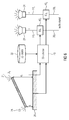
- Fig. 1 shows a block diagram of an audio processor 10 according to an embodiment.
- the audio processor 10 may comprise an input interface 12 on which at least one input audio channel 14 may be applied.
- the input interface 12 can for example connect a sound storage device, for example a hard disk with an audio output interface, or a sound generating device, for example a tuner or a microphone with an audio output interface, with a sound modifier 26.
- the audio output interface of such a device may be connected with the input audio channel 14 and can comprise a sound signal, for example music, voices or further noises.
- the audio processor 10 can comprise a detector interface 16 for receiving a detection signal indicating an information on an object 20 in the environment of the audio processor 10.
- the detector interface 16 can for example connect at least one detector 44 with the sound modifier 26.
- the detector 44 can be integrated in the audio processor 10 or it may be a further device.
- the detector 44 generates the detection signal 18 depending on an information 34 on the object 20.
- the information 34 on the object 20 can be for example a distance between the detector 44 or another predefined reference points on the electrical device and the object 20.
- the information 34 may also be an absorption characteristic or a reflection characteristic of the object 20 with respect to the at least one loudspeaker 24.
- the detector 44 can be configured for detecting the distance between the detector 44 or another predefined reference points on the electrical device and the object 20
- the detector 44 may also be configured to detect the absorption characteristic or the reflection characteristic of the object 20 with respect to the at least one loudspeaker 24.
- the detector 44 can be a detector 44 which only receives a signal.
- the detector 44 can be a camera or a stereo camera with for example a focusable lens system which can generate a distance information between the detector 44 and the object 20 based on the received image of the camera.
- the detector 44 may also comprises a proximity sensor that is configured to detect nearby objects 20.
- the detector 44 can also generate a detector signal 50 which will be reflected or absorbed by the object 20.
- the detector 44 can comprise a laser, an infrared or an ultrasound source which emitted a detector signal 50, for example an electromagnetic wave and a sensor, which detects the reflection, alternation or absorption of the emitted detector signal 50.
- the detector 44 can further be a proximity sensor which detects the influence of the object 20 on a magnetic or an electromagnetic field, generated and/or received by the detector 44.
- the detector 44 can also comprise a microphone and is configured for detecting an audio signal reflected r by the object 20 in respect to an audio signal emitted by the at least one loudspeaker 24.
- the detector 44 it is possible to get information for example about the surface of the object, the structure of the object, an angle or the distance d between the loudspeakers 22 and the object 20 or further information which influences the sound of the loudspeakers 24.
- the object 20 can for example be the floor, a wall of a room, a table or any other piece of furniture, a person or any other object 20 or surface which interacting with sound waves.
- the object 20 can be stationary or movable.
- the object 20 may be close to or far away from the loudspeaker. It may also be possible, that no object influences the sound impression of a listener 28. Interacting can be a reflection r or an absorption a of sound waves. It may also be for example that the object 20 reflected r a frequency portion of sound waves and absorbed a another frequency portion of sound waves.
- the audio processor 10 comprises an equalizer setting for an electrical device, which is mounted on a wall.
- the detector 44 detects the wall as an object 20, which influences the sound impression.
- the audio processor may reduce or eliminate this influence of the object on the sound impression by choosing an equalizer setting which compensates the influences of the wall on the sound impression. Further for example, if the electrical device stands alone in a room and the equalizer setting is designed for a case in that an object interacting with the sound waves, then the audio processor may be able to replace the current equalizer setting.
- the electrical device may have a basic equalizer setting, and depending on whether or not an object 20 is present, which may be detected by the detector signal 50, the influence of the object 20 on the sound impression of a listener may be reduced or eliminated automatically, in that the audio processor modifies at least one input audio channel. This procedure is preferably preferred in additional to the manipulation depending on the object detection.
- the sound modifier 26 which is coupled to the detector interface 16 and the input interface 12, modifies the at least one input audio channel 14 depending on the detection signal 18. Then sound modifier 26 modifies the at least one input audio channel 14 such that an influence of the object 20 on a sound impression of a listener 28 is reduced or eliminated, to obtain at least one modified channel 30.
- the sound impression of the listener 28 can be influenced by reflection r or absorption a of at least a frequency portion of the sound 22 by the object 20.
- the sound modifier 26 compensates, for example by amplifying or attenuating from at least a frequency portion of the input audio channel 14, the influences of the object 20, such that the sound 22 which approaches the listener 28 shows a sound impression for the listener 28 which is equal or similar to a sound impression situation for the listener 28 without the object 20.
- the sound modifier 26 generates the modified channel 30 which comprises the input audio channel 14 and an equalizer setting.
- the equalizer setting is explained in Fig. 4 .
- the sound modifier 26 is connected to an output interface 32.
- the output interface 32 outputs the at least one modified channel 30 to the at least one loudspeaker 24.
- the output interface 32 may connect the sound modifier 26 to loudspeakers 24, for example with a predetermined reproduction position.
- the input audio channel 14 can be designed for a predetermined reproduction position of the loudspeaker 24.
- the loudspeaker 24 is connected to the output interface 32 and transforms the modified channel 30 from the output interface 32 to sound 22 which can be heard by the listener 28.
- the sound 22 can also be reflected r or absorbed a by the object.
- the listener 28 can be a person or a small group of persons who have a similar position regarding the object 20 and the loudspeaker 24 such that for the group of listeners 28 a similar sound impression originates.
- Fig. 2 shows the loudspeaker 24 and the object 20.
- the object 20 may, for example, be a stationary object 20, for example a wall.
- the object has a distance d to the loudspeaker 24.
- the object 20 reflected at least a first part of the sound 22 emitted by the loudspeaker.
- a reflection characteristic may comprise this reflected sound r or the reflection characteristic may be for example a combination of an amount of reflected sound r and an angle of the reflected sound r in function to the frequency portion.
- the object absorbed at least a second part of the sound 22 emitted by the loudspeaker 24.
- An absorption characteristic may comprise this absorbed sound a or the absorption characteristic may be a combination of an amount of the absorbed sound a in function to the frequency portion.
- the detecting signal can comprise an information about the distance d between at least one predefined reference point on the device, for example the loudspeaker 24 or the detector, and the stationary object 20.
- the detecting signal may also comprises an information about the absorption characteristic or the reflection characteristic of the stationary object 20.
- the sound modifier can be configured for modifying the at least one input audio channel, such that the distance d or the absorption characteristic or the reflection characteristic is at least partly compensated.
- Fig. 3 shows a block diagram with a sound modifier 26 and a detector interface 16.
- the sound modifier 26 comprises a storage 38 which can store a plurality of different equalizer settings.
- the storage can be a nonvolatile memory, for example a FLASH or a ROM, or a non-retentive memory, for example a RAM.
- the storage can also be an equalizer device for example with potentiometers in analog or digital embodiments.
- An equalizer setting comprises a factor for amplifying or attenuating at least one frequency portion of an input audio signal. Examples for equalizer settings are shown in Figs. 4a and 4b .
- each different equalizer setting may be associated with the specific distance to the object or the specific absorption characteristic or a specific reflection characteristic of the object.
- the storage is connected to a retriever 40.
- the retriever 40 retrieves a selected equalizer setting from the storage 38 associated with the distance or the absorption characteristic or the reflection characteristic of the object.
- the retriever 40 is connected to the detector interface 16, which indicates by the detection signal 18 the distance of the loudspeaker to the object or the absorption characteristic of the object or the reflection characteristic of the object.
- the detection signal 18 is applied to the retriever 40.
- the retriever 40 can retrieve more than one equalizer setting.
- the sound modifier 26 comprises a controllable equalizer 42 for equalizing the at least one input audio channel 14 in accordance with the selected equalizer setting to obtain the at least one modified channel 30.
- the modified channel 30 is generated by the controllable equalizer 42 and comprises the input audio channel 14 with amplified or attenuated frequency portions according to the equalizer setting of the corresponding input audio channel.
- the controllable equalizer 42 can apply more than one equalizer setting.
- the controllable equalizer 42 may receive more than one input audio channel 14. In such an embodiment, the controllable equalizer 42 may generate a similar quantity of modified channels 30 as audio input channels 14 are received.
- Fig. 4a shows a first example of an equalizer setting 36 1 .
- the equalizer setting 36 1 shown in Fig. 4a is an example for an equalizer setting for an object which absorbed frequencies in a frequency portion of f 5 and reflected frequencies in a frequency portion of f 3 , such that the equalizer amplified frequencies in a frequency portion of f 5 and attenuated frequencies in a frequency portion of f 3 .
- the equalizer setting can for example be an equalizer setting for a small specific distance between the loudspeaker and the object.
- Fig. 4b shows a second example of an equalizer setting.
- the equalizer setting shown in Fig. 4b may, for example, be used for an object which absorbed frequency in the frequency portion of f 3 , f 4 and reflected frequencies in a frequency portion of f 1 , f 2 , f 5 , f 6 , such that the equalizer amplified frequencies in a frequency portion of f 3 , f 4 and attenuated frequencies in a frequency portion of f 1 , f 2 , f 5 , f 6 .
- An equalizer setting comprises for example a frequency range between 20Hz and 20kHz. This frequency range can be divided into one or more frequency portions. The frequency portions in Figs.
- the frequency portions of f 1 to f 6 can represent a medium frequency of the frequency portions.
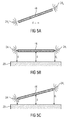
- Fig. 5a shows an electrical device 46 with two loudspeakers 24 1 , 24 2 without an object in a distance d which interacts with sound emitted by the loudspeakers 24 1 , 24 2 .
- the electrical device 46 may for example be a mobile phone (smart phone) or a tablet PC. It may also be a device like a TV, a computer or a Hi-Fi system, which stands alone in a room or is mounted on a wall, for example.
- the electrical 46 device comprises an embodiment of the invented audio processor.
- the input interface of the audio processor may comprise at least two input audio channels, each channel being associated with a predetermined reproduction position of the loudspeakers 24 1 , 24 2 , wherein the storage in the sound modifier is configured to store a first equalizer setting for a distance d between the at least two loudspeakers 24 1 , 24 2 and the object, wherein the distance d is greater than a predefined maximum distance.
- the distance d from one of the loudspeakers 24 1 , 24 2 to the object is indefinite or may be greater than the predetermined distance to the object, which may influence the sound.
- the sound modifier can be configured for amplifying or attenuating at least a frequency portion of the input audio channel, when the detection signal of the detector indicates a longer distance compared to a predetermined setting. Without the reflection from the object, for example outside in a field, some frequency portions from the input audio signal have to be amplified such that the sound impression for the listener is equal or similar to the sound impression with the object for example in a room. Preferentially, low frequency portions have to be attenuated in such an equalizer setting. Low frequency portions are usually amplified in an object area.
- a sound-hard object like a table has a different characteristic than a sound-soft object (e.g. a pillow)
- Fig. 5b shows the electrical device 46 and the object 20 interacting with sound, wherein the electrical device 46 with the two loudspeakers 24 1 , 24 2 and the object 20 are in parallel to each other.
- parallel means the difference between a first distance d 1 from the first loudspeakers 24 1 to the object 20 and a second distance d 2 from the second loudspeakers 24 2 to the object 20 is less than 10%, preferably less than 5%, of the smaller of the two loudspeaker distances d 1 , d 2 to the object 20.
- the sound modifier can be configured for amplifying or attenuating at least a frequency portion of the at least one input audio channel, when the detection signal 18 indicates a shorter distance d compared to a predetermined setting or when the detected signal indicates an additional sound reflection to the listener by the object 20.
- the storage can be configured to store a second equalizer setting for the distances d 1 , d 2 between the at least two loudspeakers 24 1 , 24 2 and the object 20, wherein the distances d 1 , d 2 are lower than the predefined maximum distance d max , and wherein the second equalizer setting for Fig. 5b is different from the first equalizer setting for Fig. 5a .
- Fig. 5c shows the electrical device 46 and an object 20 interacting with sound, wherein the two loudspeakers 24 1 , 24 2 and the object 20 are not in parallel to each other. Not in parallel means the difference between the distance d 1 from the first loudspeakers 24 1 to the object 20 and the distance d 2 from the second loudspeakers 24 2 to the object 20 is greater than 10%, preferably greater than 20%, of the smaller of the two loudspeaker distances d 1 , d 2 to the object.
- the storage is configured to store a third equalizer setting for a distance d between the at least two loudspeakers 24 1 , 24 2 and the object 20, wherein the distances d of the at least two loudspeakers 24 1 , 24 2 to the object 20 are different from each other, and wherein the third equalizer setting for Fig. 5c is different from the first equalizer setting for Fig. 5a and the second equalizer setting for Fig. 5b .
- the first loudspeaker 24 1 has a smaller distance d 1 to the object 20, then preferentially the lower frequency portion from the first input audio signal has to be amplified and if the second loudspeaker 24 2 has a longer distance to the object 20, then preferentially the lower frequency portion from the input audio signal has to be attenuated.
- FIG. 6 shows a block diagram of an embodiment of an audio processor with a controllable equalizer 42 1 , 42 2 for each input audio channel 14 1 , 14 2 .
- An input interface can comprise at least two input audio channels 14 1 , 14 2 , each input audio channel 14 1 , 14 2 being associated with a predetermined reproduction position of one of the at least two loudspeakers 24 1 , 24 2 .
- the input audio channel 14 1 , 14 2 at the input interface can be designed for a predetermined reproduction position of the loudspeakers 24 1 , 24 2 for example for a left or right loudspeaker position.
- the block diagram shows an embodiment of the electrical device with two loudspeakers 24 1 , 24 2 .
- the first loudspeaker 24 1 has a distance d 1 to the object 20.
- the second loudspeaker 24 2 has a distance d 2 to the object 20.
- the sound modifier comprises one controllable equalizer, wherein the controllable equalizer may be configured to individually equalize each input audio channel 14 1 , 14 2 or the controllable equalizer may also comprise a first controllable equalizer 42 1 and a second controllable equalizer 42 2 as shown in Fig. 6 .
- Said first and second controllable equalizers 42 1 , 42 2 can be configured to individually equalize each input audio channel 14 1 , 14 2 .
- the controllable equalizers 42 1 , 42 2 use a different equalizer setting for each input audio channel 14 1 , 14 2 , when distances d 1 , d 2 of the at least two loudspeakers 24 1 , 24 2 to the object 20 are different from each other and use only one equalizer setting for the input audio channels 14 1 , 14 2 , when the distances d 1 , d 2 of the at least two loudspeakers 24 1 , 24 2 are equal to each other or when the distances d 1 , d 2 of the at least two loudspeakers 24 1 , 24 2 are different from each other less than a predefined amount. Examples for the predefined amount of difference are mentioned in figures 5b and 5c .
- the audio processor comprises the storage 38 for storing different equalizer settings or EQ-Profiles.
- the EQ-selector or retriever 40 is connected to the storage 38 and can retrieve the equalizer setting from the storage 38.
- the retriever 40 selects an equalizer setting based on the distances d 1 , and d 2 .
- the retriever 40 provides the equalizer setting to the controllable equalizers 24 1 , 24 2 .
- Fig. 7 shows a line chart of two weighed equalizer settings 36 A , 36 B .
- the retriever can be configured to retrieve a begin equalizer setting 36 A at a beginning of a time period t begin and an end equalizer setting 36 B at an end of the time period t end .
- the retriever can be configured for weighting the begin equalizer setting 36 A within the time period, using a weight between 1 and 0; and weighting the end equalizer setting 36 B within the time period, using a further weight between 1 and 0.
- the retriever may be configured for adding together the weighted begin equalizer setting 36 WA and the weighted end equalizer setting 36 WB , in order to obtain a crossfade between the begin equalizer setting 36 A and the end equalizer setting 36 B .
- the retriever weighted the begin equalizer setting 36 A with a term since the beginning of the time period t begin wherein the weight of the begin equalizer setting 36 A decreases from 1 at the beginning of the time period t begin to 0 at the end of a time period t end .
- the retriever weighted the end equalizer setting 36 B with a term since the beginning of the time period t begin wherein the weight of the end equalizer setting 36 B increases from 0 at the beginning of the time period t begin to 1 at the end of a time period t end .
- the retriever can add together the weighted begin equalizer setting 36 WA and the weighted end equalizer setting 36 WB , to obtain the weighted equalizer setting 36 W , wherein the sum of the begin equalizer setting 36 A and the end equalizer setting 36 B may be constant.
- 36 W 36 WA + 36 WB
- the retriever may be configured to fade out the begin equalizer setting 36 A during the time period t end - t begin and fade in the end equalizer setting 36 B during the time period t end - t begin .
- the time period t end - t begin may be for example between 1 second and 10 seconds. The time period should be long enough that the listener does not realize that the sound modifier has changed from the begin equalizer setting 36 A to the end equalizer setting 36 B . However, if the time period t end - t begin for changing the equalizer settings is too long, that the risk exists, for example if the electrical device is frequently moved, that the equalizer setting will not fit to the current sound influence of the object.
- Fig. 8a shows an example of an equalizer setting in the beginning of the time period t begin for replacing an equalizer setting.
- the frequency portion f 1 is amplified to 150%
- the frequency portion f 2 is amplified to 100%
- the frequency portion f 3 is amplified to 50%.
- Fig. 8b shows an example of an equalizer setting at the half of the time for replacing an equalizer setting.
- the frequency portion f 1 is amplified to 100%
- the frequency portion f 2 is amplified to 85%
- the frequency portion f 3 is amplified to 100%.
- Fig. 8c shows an example of an equalizer setting at the end of the time period t end for replacing an equalizer setting 36.
- the frequency portion f 1 is amplified to 50%
- the frequency portion f 2 is amplified to 70%
- the frequency portion f 3 is amplified to 150%.
- Fig. 9 shows a line chart of an interpolated value for an equalizer setting 36 i between two initial equalizer settings 36 i1 , 36 i2 .
- the retriever can be configured to generate an interpolated equalizer setting 36 i .
- the interpolated equalizer setting 36 i is generated from at least a first initial equalizer setting 36 i1 and a second initial equalizer setting 36 i2 .
- the interpolated equalizer setting 36 i can comprise one or more frequency portions and the retriever can be configured to interpolate one or more frequency portions.
- the first initial equalizer setting 36 i1 may for example be associated with a first specific distance ds 1 to the object and the second initial equalizer setting 36 i2 may be associated with a second specific distance ds 2 to the object, wherein the distance d to the object as indicated by the detecting signal may be between the first specific distance ds 1 and the second specific distance ds 2 .
- the retriever is configured to generate the interpolated equalizer setting 36 i by adding a weighted first initial equalizer setting 36 wi1 and a weighted second initial equalizer setting 36 wi2 .
- the weighted first initial equalizer setting 36 wi1 may weight the first initial equalizer setting 36 i1 with a first interpolating factor I 1 .
- the first interpolating factor I 1 may have a value inversely proportional to a first difference between the distance d and the first specific distance ds 1 .
- the weighted second initial equalizer setting 36 wi2 may weight the second initial equalizer setting 36 i2 with a second interpolating factor I 2 .
- the second interpolating factor I 2 may have a value inversely proportional to a second difference between the distance d and the second specific distance ds 2 .
- the interpolating factors I 1 , I 2 may also for example be: I 1 ⁇ 1
- the weighted amount of the first equalizer setting 36 1 at the interpolated equalizer setting 36 i increases when the distance d between the loudspeakers and the object is similar to the specific distance ds 1 between the loudspeaker and the object of the first equalizer setting 36 1 .
- the weighted amount of the second equalizer setting 36 2 at the interpolated equalizer setting 36 i decreases the bigger the difference is between the distance d between the loudspeaker and the object and the specific distance ds 2 between the loudspeaker and the object of the second equalizer setting 36 2 .
- the weighted amount of the second equalizer setting 36 2 at the interpolated equalizer setting 36 i increases when the distance d between the loudspeaker and the object is similar to the specific distance ds 2 between the loudspeaker and the object of the second equalizer setting 36 2 , wherein the weighted amount of the first equalizer setting 36 1 at the interpolated equalizer setting 36 i decreases the bigger the difference is between the distance d between the loudspeaker and the object and the specific distance ds 1 between the loudspeaker and the object of the first equalizer setting 36 1 .
- the retriever can be configured to generate an interpolated equalizer setting for a specific absorption characteristic or a specific reflection characteristic.
- An interpolated equalizer setting can also be generated for replacing the begin equalizer setting with the end equalizer setting.
- An interpolated equalizer setting can also be generated to mix for example a specific absorption characteristic with a specific distance or for example a specific reflection characteristic with a specific distance.
- the equalizer settings in Figures 8a to 8c may also be seen as a first initial equalizer setting 36 i1 in Fig. 8a and a second initial equalizer setting 36 i2 in Fig. 8c , wherein the equalizer setting in Fig. 8b may be seen as an interpolated equalizer setting 36 i .
- Fig. 10 shows an electrical device 46 with a table 48 and a reflected sound signal r.
- the table 48 is an object which interacts with sound 22.
- the electrical device 46 comprises an audio processor according to the invention and at least one loudspeaker 24.
- the electrical device 46 can comprise a detector for detecting the information on the object or the table 48 and for generating the detection signal which is coupled to the detector interface.
- the detecting signal indicates an additional reflection of sound r to the listener 28 depending on the position of the electrical device 46 with respect to the table 48, wherein the sound modifier is configured to compensate the additional reflection of sound r.
- the electrical device 46 may comprise a sound modifier which is configured to amplify at least one of the input audio channels, when the detection signal indicates a covering of at least one of the loudspeakers 24.
- the covering of the loudspeaker can for example be by the electrical device 46 itself when the loudspeaker is laying against the object or the table 48, for example when the loudspeaker 24 is on the rear side of the electrical device 48 or when papers lay on the table and cover the electrical device.
- aspects have been described in the context of an apparatus, it is clear that these aspects also represent a description of the corresponding method, where a block or device corresponds to a method step or a feature of a method step. Analogously, aspects described in the context of a method step also represent a description of a corresponding block or item or feature of a corresponding apparatus.
- the inventive encoded audio signal can be stored on a digital storage medium or can be transmitted on a transmission medium such as a wireless transmission medium or a wired transmission medium such as the Internet.
- embodiments of the invention can be implemented in hardware or in software.
- the implementation can be performed using a digital storage medium, for example a floppy disk, a DVD, a CD, a ROM, a PROM, an EPROM, an EEPROM or a FLASH memory, having electronically readable control signals stored thereon, which cooperate (or are capable of cooperating) with a programmable computer system such that the respective method is performed.
- a digital storage medium for example a floppy disk, a DVD, a CD, a ROM, a PROM, an EPROM, an EEPROM or a FLASH memory, having electronically readable control signals stored thereon, which cooperate (or are capable of cooperating) with a programmable computer system such that the respective method is performed.
- Some embodiments according to the invention comprise a data carrier having electronically readable control signals, which are capable of cooperating with a programmable computer system, such that one of the methods described herein is performed.
- embodiments of the present invention can be implemented as a computer program product with a program code, the program code being operative for performing one of the methods when the computer program product runs on a computer.
- the program code may for example be stored on a machine readable carrier.
- inventions comprise the computer program for performing one of the methods described herein, stored on a machine readable carrier.
- an embodiment of the inventive method is, therefore, a computer program having a program code for performing one of the methods described herein, when the computer program runs on a computer.
- a further embodiment of the inventive methods is, therefore, a data carrier (or a digital storage medium, or a computer-readable medium) comprising, recorded thereon, the computer program for performing one of the methods described herein.
- a further embodiment of the inventive method is, therefore, a data stream or a sequence of signals representing the computer program for performing one of the methods described herein.
- the data stream or the sequence of signals may for example be configured to be transferred via a data communication connection, for example via the Internet.
- a further embodiment comprises a processing means, for example a computer, or a programmable logic device, configured to or adapted to perform one of the methods described herein.
- a processing means for example a computer, or a programmable logic device, configured to or adapted to perform one of the methods described herein.
- a further embodiment comprises a computer having installed thereon the computer program for performing one of the methods described herein.
- a programmable logic device for example a field programmable gate array
- a field programmable gate array may cooperate with a microprocessor in order to perform one of the methods described herein.
- the methods are preferably performed by any hardware apparatus.
Landscapes
- Physics & Mathematics (AREA)
- Engineering & Computer Science (AREA)
- Acoustics & Sound (AREA)
- Signal Processing (AREA)
- Stereophonic System (AREA)
- Circuit For Audible Band Transducer (AREA)
Abstract
An audio processor, wherein the audio processor (10) comprising an input interface (12) for receiving at least one input audio channels (14) a detector interface (16) for receiving a detection signal (18) indicating an information (34) on an object (20) interacting with sound (22) emitted by at least one loudspeaker (24). Further the audio processor comprising a sound modifier (26) for modifying the at least one input audio channel (14) depending on the detection signal (18) such that an influence of the object (20) on a sound impression of a listener (28) is reduced or eliminated, to obtain at least one modified channel (30) and an output interface (32) for outputting the at least one modified channel (30) to the at least one loudspeaker (24).
Description
- The present invention relates to an audio processor and to a method for audio processing. Moreover, the present invention relates to an electrical device comprising such an audio processor.
- From the state of the art audio processors are known, for example, which generate an output signal from an input audio signal. Such an output signal may be applied to a fixed installed loudspeaker from an audio equipment. Depending on the structure of a room and the position of the loudspeakers some frequency portions can be more or less absorbed or reflected in the room. For compensating the absorption and reflection and to improve the sound impression of a listener, some frequency portions of the audio signal will be amplified or damped by an equalizer such that a loudspeaker signal which is adapted with the structure of the room can be output to the loudspeaker.
- electrical devices, as for example a table PC or a smartphone, can also have loudspeakers. Such devices and their loudspeakers are typically not fixedly installed in a room, but rather they will be changed in their position and orientation in the room, whereby the position of the loudspeaker in the room is often changed and as a consequence the acoustic sound waves will be absorbed or reflected, respectively. Further, if the electrical device or the loudspeaker, respectively, is covered, for example because the electrical device is lying on a surface with the loudspeaker against the surface or the loudspeaker is covered by coincidence with a paper, as a consequence the reflection or the absorption of an audio signal which will be output to the loudspeaker will be changed.
- The object of the present invention is to provide an audio processor which can provide an adapted audio signal to a loudspeaker by often changed reflection or absorption, respectively, and to provide an electrical device which uses such an audio processor.
- This object is solved by the subject matter of the independent claims.
- According to an embodiment of the invention, the audio processor comprises an input interface for receiving at least one input audio channel and a detector interface for receiving a detection signal indicating an information on an object interacting with sound emitted by at least one loudspeaker. Further, the audio processor comprises a sound modifier for modifying the at least one input audio channel depending on the detection signal such that an influence of the object on a sound impression of a listener is reduced or eliminated, to obtain at least one modified channel and an output interface for outputting the at least one modified channel to the at least one loudspeaker.
- The present invention is based on the idea of an improved audio processor comprising a detector interface for receiving a detection signal, which indicates an information on an object interacting with the sound emitted by the loudspeaker through the detector interface, a signal can be received which indicates to the audio processor an information about the reflection or absorption of an audio signal in the environment of the loudspeakers. Based on this information, the audio processor can modify the input audio channel at the absorption or reflection of an object in the environment of the loudspeakers such that an influence of the object on a sound impression of a listener can be reduced or eliminated. Through the detection of the environment by the detection signal, the environment can be detected automatically which enables a quick adaption of an equalizer setting to the sound conditions at the environment.
- According to an embodiment of the audio processor, the input interface comprises at least one input audio channel, each channel being associated with a predetermined reproduction position. If the audio processor comprises more than one input audio channel, then the input audio signal often has an information which determined a specific position of a loudspeaker such that the impression of a listener can be improved when the signal is applied to a loudspeaker with a determined position.
- According to an embodiment of the audio processor, the object is a stationary object, wherein the detection signal comprises an information about a distance between the at least one loudspeaker and the stationary object or an information about an absorption characteristic or a reflection characteristic of the stationary object, and wherein the sound modifier is configured for modifying the at least one input audio channel such that the distance or the absorption characteristic or the reflection characteristic is at least partly compensated. Through the information about the distance between the loudspeaker and the stationary object or the information about an absorption characteristic or a reflection characteristic of the stationary object, the audio processor is able to modify the input audio channel such that the influence of the object on a sound impression of a listener is reduced or eliminated.
- According to an embodiment of the audio processor, the sound modifier is configured for amplifying at least a frequency portion of the at least one input audio channel, when the detection signal indicates a longer distance compared to a predetermined setting, or for attenuating at least a frequency portion of the at least one input audio channel, when the detection signal indicates a shorter distance compared to a predetermined setting. This applies under the assumption that a larger distance to an object means that a signal has to be amplified. However, if the loudspeaker is on the rear side of the electrical device, exactly the opposite could happen, namely that an amplification is necessary because of the near distance. Further, the sound modifier can be configured for attenuating at least a frequency portion of the at least one input audio channel, when the detected signal indicates an additional sound reflection to the listener by the object. A frequency spectrum of an audio signal will be variously reflected. The reflection can be dependent on the distance between the loudspeaker and the object, the reflection of the object and the frequency of the audio signal. For compensating such an effect the sound modifier is configured to amplify or attenuate at least a frequency portion.
- According to an embodiment of the audio processor, the information on the object indicates the distance to the object or the absorption characteristic or a reflection characteristic of the object, wherein the sound modifier comprises a storage storing a plurality of different equalizer settings, each different equalizer setting being associated with a first or a second specific distance to the object or the specific absorption characteristic or a specific reflection characteristic of the object. Further, the sound modifier comprises a retriever for retrieving a selected equalizer setting associated with the distance or the absorption characteristic or a reflection characteristic of the object indicated by the detection signal and a controllable equalizer for equalizing the at least one input audio channel, in accordance with the selected equalizer setting, to obtain the at least one modified channel. Through the storage, which stores a plurality of different equalizer settings, and the retriever, which retrieves a selected equalizer setting, and a controllable equalizer, which equalizes the input audio channel, it is possible to store different equalizer settings for different situations, regarding the environment of the audio processor and to generate a modified channel which can be applied to at least one loudspeaker.
- According to an embodiment of the audio processor, wherein the storage is configured to store a first equalizer setting for a distance between the loudspeaker and the object, wherein the distance is greater than a predefined maximum distance. Further, the storage is configured to store a second equalizer setting, for a distance between the loudspeaker and the object, wherein the distance is lower than the predefined maximum distance, wherein the second equalizer setting is different from the first equalizer setting, and a third equalizer setting, for a distance between the loudspeaker and the object, wherein the distances of the at least two loudspeakers to the object are different from each other, wherein the third equalizer setting is different from the first equalizer setting and the second equalizer setting. The first equalizer setting is applied when an object is far from the loudspeaker. The second equalizer setting is applied when an object is within a distance to the loudspeaker such that it has an influence on the sound. The third equalizer setting is applied when two loudspeakers and the object are not in parallel to each other. Each equalizer setting can compensate the specific influence of the object on the sound impression. Actually, the "distance" is not the main reason, but rather the reflection characteristic of the object. This of course depends on the distance to the object and is proportional to the distance for acoustically hard objects (tables, walls).
- According to an embodiment of the audio processor, the input interface comprises at least two input audio channels, each channel being associated with a predetermined reproduction position. The sound modifier comprises a controllable equalizer, wherein the controllable equalizer is configured to individually equalize each input audio channel. The controllable equalizer uses a different equalizer setting for each input audio channel, when distances of the at least two loudspeakers to the object are different from each other and uses only one equalizer setting for the input audio channels when the distances of the at least two loudspeakers are equal to each other or when the distances of the at least two loudspeakers are different from each other less than a predefined amount. Through individually equalizing the input audio channels it is possible to obtain an individual modified channel to each loudspeaker.
- According to an embodiment of the audio processor, the retriever is configured to retrieve a begin equalizer setting at a beginning of a time period and an end equalizer setting at an end of the time period. The retriever is configured for weighting the begin equalizer setting within the time period, using a weight between 1 and 0, and the retriever is configured to weight the end equalizer setting within the time period, using a further weight between 1 and 0. The retriever is further configured for adding together the weighted begin equalizer setting and the weighted end equalizer setting, in order to obtain a crossfade between the begin equalizer setting and the end equalizer setting. Through the crossfading between the begin equalizer setting and the end equalizer setting it is possible to make a smoother transition between the begin equalizer setting and the end equalizer setting, such that a listener does not realize that the equalizer setting has changed.
- According to a further embodiment of the audio processor, the retriever is configured to generate an interpolated equalizer setting from at least a first initial equalizer setting and a second initial equalizer setting. The first initial equalizer setting is associated with a first specific distance to the object and the second initial equalizer setting is associated with a second specific distance to the object, wherein the distance to the object as indicated by the detecting signal is between the first specific distance and the second specific distance. The retriever is configured to generate the interpolated equalizer setting by adding a weighted first initial equalizer setting, which weighting the first initial equalizer setting with a first interpolating factor wherein the first interpolating factor has a value inversely to a first difference between the distance and the first specific distance and a weighted second initial equalizer setting, which weighting the second initial equalizer setting with a second interpolating factor, wherein the second interpolating factor has a value inversely to a second difference between the distance and the second specific distance. Through the generation of an interpolated equalizer setting it is possible to generate an equalizer setting which is finally adapted to the distance as indicated by the detecting signal, thereby it needs less stored equalizer setting in the storage and a finer equalizing of the equalizer settings for varying distances between the loudspeaker and the object is possible.
- According to an embodiment of the audio processor, the audio processor further comprises a detector for detecting the information on the object and for generating the detection signal which is coupled to the detector interface. The detector is configured to detect the distance between at least one predefined reference points on the device and the object or the absorption characteristic or the reflection characteristic of the object with respect to the at least one loudspeaker. Through the detector the audio processor is able to detect the information on the object in the environment, for example the distance between the loudspeakers, as the predefined reference point and the object or the absorption or the reflection characteristic of the object.
- According to an embodiment of the audio processor, the detector comprises a proximity sensor that is configured to detect the object. Further the detector may comprises a microphone and is configured for detecting an audio signal reflected by the object in respect to an audio signal emitted by the at least one loudspeaker. When the detector comprises a microphone which detects an audio signal reflected by the object it is possible to generate a reflection characteristic of the object depending on the emitted modified channel and to compensate this reflection characteristic by an equalizer setting.
- The present invention is further based on the idea of creating an improved electrical device, comprising an audio processor according to the previously described embodiments and the at least one loudspeaker and a detector for detecting the information on the object and for generating the detection signal which is coupled to the detector interface. Through the integration of the audio processor in an electrical device, which can change the position and the orientation in the room such that it comes to a various reflection or absorption of the audio signal in the room and to a different sound impression for the listener, the influence of the object can be reduced or eliminated by modifying the input audio channel with a described audio processor. The general goal is to deliver a constant audio quality to the listener, independent of any close-by object or the orientation of the electrical device towards these objects.
- According to an embodiment of the electrical device, the object is a table and the detector is configured to generate the detecting signal, indicating an additional reflection of sound to the listener depending on the position of the electrical device with respect to the table, wherein the sound modifier is configured to compensate the additional reflection of sound. Through the table, sound from the electrical device will be reflected to the listener. The detector is configured to generate the detecting signal which enables the sound processor, depending on the position of the electrical device with respect to the table, to modify the input audio channel such that an influence of the table on the sound impression of the listener is reduced or eliminated.
- According to an embodiment of the electrical device, the sound modifier is configured to amplify at least one of the input audio channels, when the detection signal indicates a covering of at least one of the loudspeakers. Through amplifying the input audio channel of a covered loudspeaker the covering can be compensated such that the sound impression of the listener is reduced or eliminated. The amplifying can be limited to a frequency portion, such that frequency portions which are more strongly affected will be more strongly amplified. Moreover, the amplifying can be time-dependent if the distance to objects is changed.
- A further embodiment according to the invention provides a method for audio processing, comprising the following steps:
- Receiving at least one input audio channel, receiving a detection signal indicating an information on an object interacting with sound emitted by at least one loudspeaker.
- Modifying the at least one input audio channel depending on the detection signal such that an influence of the object on a sound impression of a listener is reduced or eliminated, to obtain at least one modified channel. And:
- Outputting the at least one modified channel to at least one loudspeaker.
- A further embodiment according to the invention provides a computer program comprising a program code for executing the method, when the computer program is running on a computer or on a processor.
- In the following, embodiments of the present invention are described in more detail with reference to the figures, in which:
- Fig. 1
- shows a block diagram of an audio processor according to an embodiment of the invention;
- Fig. 2
- shows a loudspeaker with a stationary object;
- Fig. 3
- shows a block diagram of a sound modifier and a detector interface;
- Fig. 4a
- shows a first example of an equalizer setting;
- Fig. 4b
- shows a second example of an equalizer setting;
- Fig. 5a
- shows an electrical device with two loudspeakers without an object which interacts with sound emitted by the loudspeakers;
- Fig. 5b
- shows the electrical device and the object interacting with sound, wherein the electrical device with the two loudspeakers and the object are in parallel to each other;
- Fig. 5c
- shows the electrical device and an object interacting with sound, wherein the two loudspeakers and the object are not in parallel to each other;
- Fig. 6
- shows a block diagram of an audio processor with one controllable equalizer for each audio channel;
- Fig. 7
- shows a line chart of two weighed equalizer settings;
- Fig. 8a
- shows an example of an equalizer setting in the beginning of the replacing of an equalizer setting;
- Fig. 8b
- shows an example of an equalizer setting at the half of the time for replacing the equalizer setting;
- Fig. 8c
- shows an example of an equalizer setting at the end of the replacing the equalizer setting;
- Fig. 9
- shows a line chart of an interpolated value for an equalizer setting between two initial equalizer settings;
- Fig. 10
- shows an electrical device with a sound signal reflected from a table.
- Equal or equivalent elements or elements with equal or equivalent functionality are denoted in the following description by equal or equivalent reference numerals.
-
Fig. 1 shows a block diagram of anaudio processor 10 according to an embodiment. Theaudio processor 10 may comprise aninput interface 12 on which at least oneinput audio channel 14 may be applied. Theinput interface 12 can for example connect a sound storage device, for example a hard disk with an audio output interface, or a sound generating device, for example a tuner or a microphone with an audio output interface, with asound modifier 26. The audio output interface of such a device may be connected with theinput audio channel 14 and can comprise a sound signal, for example music, voices or further noises. - Further, the
audio processor 10 can comprise adetector interface 16 for receiving a detection signal indicating an information on anobject 20 in the environment of theaudio processor 10. Thedetector interface 16 can for example connect at least onedetector 44 with thesound modifier 26. Thedetector 44 can be integrated in theaudio processor 10 or it may be a further device. Thedetector 44 generates thedetection signal 18 depending on aninformation 34 on theobject 20. Theinformation 34 on theobject 20 can be for example a distance between thedetector 44 or another predefined reference points on the electrical device and theobject 20. Theinformation 34 may also be an absorption characteristic or a reflection characteristic of theobject 20 with respect to the at least oneloudspeaker 24. Thedetector 44 can be configured for detecting the distance between thedetector 44 or another predefined reference points on the electrical device and theobject 20 Thedetector 44 may also be configured to detect the absorption characteristic or the reflection characteristic of theobject 20 with respect to the at least oneloudspeaker 24. In embodiments, thedetector 44 can be adetector 44 which only receives a signal. For example, thedetector 44 can be a camera or a stereo camera with for example a focusable lens system which can generate a distance information between thedetector 44 and theobject 20 based on the received image of the camera. Thedetector 44 may also comprises a proximity sensor that is configured to detect nearby objects 20. Thedetector 44 can also generate adetector signal 50 which will be reflected or absorbed by theobject 20. For example thedetector 44 can comprise a laser, an infrared or an ultrasound source which emitted adetector signal 50, for example an electromagnetic wave and a sensor, which detects the reflection, alternation or absorption of the emitteddetector signal 50. Exemplarily, thedetector 44 can further be a proximity sensor which detects the influence of theobject 20 on a magnetic or an electromagnetic field, generated and/or received by thedetector 44. Thedetector 44 can also comprise a microphone and is configured for detecting an audio signal reflected r by theobject 20 in respect to an audio signal emitted by the at least oneloudspeaker 24. - Depending on the
detector 44 it is possible to get information for example about the surface of the object, the structure of the object, an angle or the distance d between theloudspeakers 22 and theobject 20 or further information which influences the sound of theloudspeakers 24. - The
object 20 can for example be the floor, a wall of a room, a table or any other piece of furniture, a person or anyother object 20 or surface which interacting with sound waves. Theobject 20 can be stationary or movable. Theobject 20 may be close to or far away from the loudspeaker. It may also be possible, that no object influences the sound impression of alistener 28. Interacting can be a reflection r or an absorption a of sound waves. It may also be for example that theobject 20 reflected r a frequency portion of sound waves and absorbed a another frequency portion of sound waves. - It may also be possible that the
audio processor 10 comprises an equalizer setting for an electrical device, which is mounted on a wall. Thedetector 44 detects the wall as anobject 20, which influences the sound impression. The audio processor may reduce or eliminate this influence of the object on the sound impression by choosing an equalizer setting which compensates the influences of the wall on the sound impression. Further for example, if the electrical device stands alone in a room and the equalizer setting is designed for a case in that an object interacting with the sound waves, then the audio processor may be able to replace the current equalizer setting. In general the electrical device may have a basic equalizer setting, and depending on whether or not anobject 20 is present, which may be detected by thedetector signal 50, the influence of theobject 20 on the sound impression of a listener may be reduced or eliminated automatically, in that the audio processor modifies at least one input audio channel. This procedure is preferably preferred in additional to the manipulation depending on the object detection. - The
sound modifier 26, which is coupled to thedetector interface 16 and theinput interface 12, modifies the at least oneinput audio channel 14 depending on thedetection signal 18. Thensound modifier 26 modifies the at least oneinput audio channel 14 such that an influence of theobject 20 on a sound impression of alistener 28 is reduced or eliminated, to obtain at least one modifiedchannel 30. The sound impression of thelistener 28 can be influenced by reflection r or absorption a of at least a frequency portion of the sound 22 by theobject 20. Thesound modifier 26 compensates, for example by amplifying or attenuating from at least a frequency portion of theinput audio channel 14, the influences of theobject 20, such that the sound 22 which approaches thelistener 28 shows a sound impression for thelistener 28 which is equal or similar to a sound impression situation for thelistener 28 without theobject 20. Thesound modifier 26 generates the modifiedchannel 30 which comprises theinput audio channel 14 and an equalizer setting. The equalizer setting is explained inFig. 4 . - The
sound modifier 26 is connected to anoutput interface 32. Theoutput interface 32 outputs the at least one modifiedchannel 30 to the at least oneloudspeaker 24. Theoutput interface 32 may connect thesound modifier 26 toloudspeakers 24, for example with a predetermined reproduction position. As mentioned above, theinput audio channel 14 can be designed for a predetermined reproduction position of theloudspeaker 24. - The
loudspeaker 24 is connected to theoutput interface 32 and transforms the modifiedchannel 30 from theoutput interface 32 to sound 22 which can be heard by thelistener 28. The sound 22 can also be reflected r or absorbed a by the object. Thelistener 28 can be a person or a small group of persons who have a similar position regarding theobject 20 and theloudspeaker 24 such that for the group of listeners 28 a similar sound impression originates. -
Fig. 2 shows theloudspeaker 24 and theobject 20. Theobject 20 may, for example, be astationary object 20, for example a wall. The object has a distance d to theloudspeaker 24. Theobject 20 reflected at least a first part of the sound 22 emitted by the loudspeaker. A reflection characteristic may comprise this reflected sound r or the reflection characteristic may be for example a combination of an amount of reflected sound r and an angle of the reflected sound r in function to the frequency portion. Further, the object absorbed at least a second part of the sound 22 emitted by theloudspeaker 24. An absorption characteristic may comprise this absorbed sound a or the absorption characteristic may be a combination of an amount of the absorbed sound a in function to the frequency portion. The detecting signal can comprise an information about the distance d between at least one predefined reference point on the device, for example theloudspeaker 24 or the detector, and thestationary object 20. The detecting signal may also comprises an information about the absorption characteristic or the reflection characteristic of thestationary object 20. The sound modifier can be configured for modifying the at least one input audio channel, such that the distance d or the absorption characteristic or the reflection characteristic is at least partly compensated. -
Fig. 3 shows a block diagram with asound modifier 26 and adetector interface 16. Thesound modifier 26 comprises astorage 38 which can store a plurality of different equalizer settings. The storage can be a nonvolatile memory, for example a FLASH or a ROM, or a non-retentive memory, for example a RAM. The storage can also be an equalizer device for example with potentiometers in analog or digital embodiments. An equalizer setting comprises a factor for amplifying or attenuating at least one frequency portion of an input audio signal. Examples for equalizer settings are shown inFigs. 4a and 4b . In embodiments of the invention, each different equalizer setting may be associated with the specific distance to the object or the specific absorption characteristic or a specific reflection characteristic of the object. The storage is connected to aretriever 40. Theretriever 40 retrieves a selected equalizer setting from thestorage 38 associated with the distance or the absorption characteristic or the reflection characteristic of the object. Theretriever 40 is connected to thedetector interface 16, which indicates by thedetection signal 18 the distance of the loudspeaker to the object or the absorption characteristic of the object or the reflection characteristic of the object. Thedetection signal 18 is applied to theretriever 40. In embodiments, theretriever 40 can retrieve more than one equalizer setting. - Further the
sound modifier 26 comprises acontrollable equalizer 42 for equalizing the at least oneinput audio channel 14 in accordance with the selected equalizer setting to obtain the at least one modifiedchannel 30. The modifiedchannel 30 is generated by thecontrollable equalizer 42 and comprises theinput audio channel 14 with amplified or attenuated frequency portions according to the equalizer setting of the corresponding input audio channel. In embodiments, thecontrollable equalizer 42 can apply more than one equalizer setting. In embodiments, thecontrollable equalizer 42 may receive more than oneinput audio channel 14. In such an embodiment, thecontrollable equalizer 42 may generate a similar quantity of modifiedchannels 30 asaudio input channels 14 are received. -
Fig. 4a shows a first example of an equalizer setting 361. The equalizer setting 361 shown inFig. 4a is an example for an equalizer setting for an object which absorbed frequencies in a frequency portion of f5 and reflected frequencies in a frequency portion of f3, such that the equalizer amplified frequencies in a frequency portion of f5 and attenuated frequencies in a frequency portion of f3. The equalizer setting can for example be an equalizer setting for a small specific distance between the loudspeaker and the object. -
Fig. 4b shows a second example of an equalizer setting. The equalizer setting shown inFig. 4b may, for example, be used for an object which absorbed frequency in the frequency portion of f3, f4 and reflected frequencies in a frequency portion of f1, f2, f5, f6, such that the equalizer amplified frequencies in a frequency portion of f3, f4 and attenuated frequencies in a frequency portion of f1, f2, f5, f6. An equalizer setting comprises for example a frequency range between 20Hz and 20kHz. This frequency range can be divided into one or more frequency portions. The frequency portions inFigs. 4a and 4b are labeled with f1, to f6. The frequency portions of f1 to f6 can represent a medium frequency of the frequency portions. The medium frequency portion can represent for example an approximately logarithmic distribution of the frequency range, such that for example for a frequency range of 20Hz to 20kHz, the medium frequency of the frequency portions are f1, = 50Hz; f2 = 150Hz; f3 = 500Hz; f4 = 1500Hz; f5, = 5kHz; f6 = 15kHz. -
Fig. 5a shows anelectrical device 46 with twoloudspeakers loudspeakers electrical device 46 may for example be a mobile phone (smart phone) or a tablet PC. It may also be a device like a TV, a computer or a Hi-Fi system, which stands alone in a room or is mounted on a wall, for example. - The electrical 46 device comprises an embodiment of the invented audio processor. The input interface of the audio processor may comprise at least two input audio channels, each channel being associated with a predetermined reproduction position of the
loudspeakers loudspeakers - The distance d from one of the
loudspeakers -
Fig. 5b shows theelectrical device 46 and theobject 20 interacting with sound, wherein theelectrical device 46 with the twoloudspeakers object 20 are in parallel to each other. In parallel means the difference between a first distance d1 from thefirst loudspeakers 241 to theobject 20 and a second distance d2 from thesecond loudspeakers 242 to theobject 20 is less than 10%, preferably less than 5%, of the smaller of the two loudspeaker distances d1, d2 to theobject 20. The sound modifier can be configured for amplifying or attenuating at least a frequency portion of the at least one input audio channel, when thedetection signal 18 indicates a shorter distance d compared to a predetermined setting or when the detected signal indicates an additional sound reflection to the listener by theobject 20. The storage can be configured to store a second equalizer setting for the distances d1, d2 between the at least twoloudspeakers object 20, wherein the distances d1, d2 are lower than the predefined maximum distance dmax, and wherein the second equalizer setting forFig. 5b is different from the first equalizer setting forFig. 5a . With the reflection from theobject 20 some frequency portions from the input audio signal have to be amplified so that the sound impression for the listener is equal or similar to the sound impression without the object. Preferentially, lower frequency portions have to be amplified. -
Fig. 5c shows theelectrical device 46 and anobject 20 interacting with sound, wherein the twoloudspeakers object 20 are not in parallel to each other. Not in parallel means the difference between the distance d1 from thefirst loudspeakers 241 to theobject 20 and the distance d2 from thesecond loudspeakers 242 to theobject 20 is greater than 10%, preferably greater than 20%, of the smaller of the two loudspeaker distances d1, d2 to the object. The storage is configured to store a third equalizer setting for a distance d between the at least twoloudspeakers object 20, wherein the distances d of the at least twoloudspeakers object 20 are different from each other, and wherein the third equalizer setting forFig. 5c is different from the first equalizer setting forFig. 5a and the second equalizer setting forFig. 5b . For example, if thefirst loudspeaker 241 has a smaller distance d1 to theobject 20, then preferentially the lower frequency portion from the first input audio signal has to be amplified and if thesecond loudspeaker 242 has a longer distance to theobject 20, then preferentially the lower frequency portion from the input audio signal has to be attenuated. -
Fig. 6 shows a block diagram of an embodiment of an audio processor with acontrollable equalizer input audio channel input audio channels input audio channel loudspeakers input audio channel loudspeakers - The block diagram shows an embodiment of the electrical device with two
loudspeakers first loudspeaker 241 has a distance d1 to theobject 20. Thesecond loudspeaker 242 has a distance d2 to theobject 20. The sound modifier comprises one controllable equalizer, wherein the controllable equalizer may be configured to individually equalize eachinput audio channel controllable equalizer 421 and a secondcontrollable equalizer 422 as shown inFig. 6 . Said first and secondcontrollable equalizers input audio channel controllable equalizers input audio channel loudspeakers object 20 are different from each other and use only one equalizer setting for theinput audio channels loudspeakers loudspeakers figures 5b and 5c . - Further, the audio processor comprises the
storage 38 for storing different equalizer settings or EQ-Profiles. The EQ-selector orretriever 40 is connected to thestorage 38 and can retrieve the equalizer setting from thestorage 38. Theretriever 40 selects an equalizer setting based on the distances d1, and d2. Theretriever 40 provides the equalizer setting to thecontrollable equalizers -
Fig. 7 shows a line chart of two weighedequalizer settings - For example, the retriever weighted the begin equalizer setting 36A with a term since the beginning of the time period tbegin, wherein the weight of the begin equalizer setting 36A decreases from 1 at the beginning of the time period tbegin to 0 at the end of a time period tend. Further, the retriever weighted the end equalizer setting 36B with a term since the beginning of the time period tbegin, wherein the weight of the end equalizer setting 36B increases from 0 at the beginning of the time period tbegin to 1 at the end of a time period tend. The retriever can add together the weighted begin equalizer setting 36WA and the weighted end equalizer setting 36WB, to obtain the weighted equalizer setting 36W, wherein the sum of the begin equalizer setting 36A and the end equalizer setting 36B may be constant.

- For example, for a time period in the middle between tbegin and tend the weight of each equalizer setting may be 0.5

- The retriever may be configured to fade out the begin equalizer setting 36A during the time period tend - tbegin and fade in the end equalizer setting 36B during the time period tend - tbegin. The time period tend - tbegin may be for example between 1 second and 10 seconds. The time period should be long enough that the listener does not realize that the sound modifier has changed from the begin equalizer setting 36A to the end equalizer setting 36B. However, if the time period tend - tbegin for changing the equalizer settings is too long, that the risk exists, for example if the electrical device is frequently moved, that the equalizer setting will not fit to the current sound influence of the object.
-
Fig. 8a shows an example of an equalizer setting in the beginning of the time period tbegin for replacing an equalizer setting. The frequency portion f1 is amplified to 150%, the frequency portion f2 is amplified to 100% and the frequency portion f3 is amplified to 50%. -
Fig. 8b shows an example of an equalizer setting at the half of the time for replacing an equalizer setting. The frequency portion f1 is amplified to 100%, the frequency portion f2 is amplified to 85% and the frequency portion f3 is amplified to 100%. -
Fig. 8c shows an example of an equalizer setting at the end of the time period tend for replacing an equalizer setting 36. The frequency portion f1 is amplified to 50%, the frequency portion f2 is amplified to 70% and the frequency portion f3 is amplified to 150%. -
Fig. 9 shows a line chart of an interpolated value for an equalizer setting 36i between twoinitial equalizer settings - For example, the interpolated equalizer setting 36i may be calculated by the following formula


wherein the interpolating factors I1, I2 are inverse proportional to the difference of the absolute value of the distances d and a first or a second specific distance ds1, ds2.
- The interpolating factors I1, I2 may also for example be:

- The weighted amount of the first equalizer setting 361 at the interpolated equalizer setting 36i increases when the distance d between the loudspeakers and the object is similar to the specific distance ds1 between the loudspeaker and the object of the first equalizer setting 361. The weighted amount of the second equalizer setting 362 at the interpolated equalizer setting 36i decreases the bigger the difference is between the distance d between the loudspeaker and the object and the specific distance ds2 between the loudspeaker and the object of the second equalizer setting 362. The weighted amount of the second equalizer setting 362 at the interpolated equalizer setting 36i increases when the distance d between the loudspeaker and the object is similar to the specific distance ds2 between the loudspeaker and the object of the second equalizer setting 362, wherein the weighted amount of the first equalizer setting 361 at the interpolated equalizer setting 36i decreases the bigger the difference is between the distance d between the loudspeaker and the object and the specific distance ds1 between the loudspeaker and the object of the first equalizer setting 361.
- In further embodiments of the invention the retriever can be configured to generate an interpolated equalizer setting for a specific absorption characteristic or a specific reflection characteristic. An interpolated equalizer setting can also be generated for replacing the begin equalizer setting with the end equalizer setting. An interpolated equalizer setting can also be generated to mix for example a specific absorption characteristic with a specific distance or for example a specific reflection characteristic with a specific distance.
- The equalizer settings in
Figures 8a to 8c may also be seen as a first initial equalizer setting 36i1 inFig. 8a and a second initial equalizer setting 36i2 inFig. 8c , wherein the equalizer setting inFig. 8b may be seen as an interpolated equalizer setting 36i. -
Fig. 10 shows anelectrical device 46 with a table 48 and a reflected sound signal r. The table 48 is an object which interacts withsound 22. In embodiments, theelectrical device 46 comprises an audio processor according to the invention and at least oneloudspeaker 24. Further theelectrical device 46 can comprise a detector for detecting the information on the object or the table 48 and for generating the detection signal which is coupled to the detector interface. The detecting signal indicates an additional reflection of sound r to thelistener 28 depending on the position of theelectrical device 46 with respect to the table 48, wherein the sound modifier is configured to compensate the additional reflection of sound r. - In further embodiments the
electrical device 46 may comprise a sound modifier which is configured to amplify at least one of the input audio channels, when the detection signal indicates a covering of at least one of theloudspeakers 24. The covering of the loudspeaker can for example be by theelectrical device 46 itself when the loudspeaker is laying against the object or the table 48, for example when theloudspeaker 24 is on the rear side of theelectrical device 48 or when papers lay on the table and cover the electrical device. - Although some aspects have been described in the context of an apparatus, it is clear that these aspects also represent a description of the corresponding method, where a block or device corresponds to a method step or a feature of a method step. Analogously, aspects described in the context of a method step also represent a description of a corresponding block or item or feature of a corresponding apparatus.
- The inventive encoded audio signal can be stored on a digital storage medium or can be transmitted on a transmission medium such as a wireless transmission medium or a wired transmission medium such as the Internet.
- Depending on certain implementation requirements, embodiments of the invention can be implemented in hardware or in software. The implementation can be performed using a digital storage medium, for example a floppy disk, a DVD, a CD, a ROM, a PROM, an EPROM, an EEPROM or a FLASH memory, having electronically readable control signals stored thereon, which cooperate (or are capable of cooperating) with a programmable computer system such that the respective method is performed.
- Some embodiments according to the invention comprise a data carrier having electronically readable control signals, which are capable of cooperating with a programmable computer system, such that one of the methods described herein is performed.
- Generally, embodiments of the present invention can be implemented as a computer program product with a program code, the program code being operative for performing one of the methods when the computer program product runs on a computer. The program code may for example be stored on a machine readable carrier.
- Other embodiments comprise the computer program for performing one of the methods described herein, stored on a machine readable carrier.
- In other words, an embodiment of the inventive method is, therefore, a computer program having a program code for performing one of the methods described herein, when the computer program runs on a computer.
- A further embodiment of the inventive methods is, therefore, a data carrier (or a digital storage medium, or a computer-readable medium) comprising, recorded thereon, the computer program for performing one of the methods described herein.
- A further embodiment of the inventive method is, therefore, a data stream or a sequence of signals representing the computer program for performing one of the methods described herein. The data stream or the sequence of signals may for example be configured to be transferred via a data communication connection, for example via the Internet.
- A further embodiment comprises a processing means, for example a computer, or a programmable logic device, configured to or adapted to perform one of the methods described herein.
- A further embodiment comprises a computer having installed thereon the computer program for performing one of the methods described herein.
- In some embodiments, a programmable logic device (for example a field programmable gate array) may be used to perform some or all of the functionalities of the methods described herein. In some embodiments, a field programmable gate array may cooperate with a microprocessor in order to perform one of the methods described herein. Generally, the methods are preferably performed by any hardware apparatus.
- The above described embodiments are merely illustrative for the principles of the present invention. It is understood that modifications and variations of the arrangements and the details described herein will be apparent to others skilled in the art. It is the intent, therefore, to be limited only by the scope of the impending patent claims and not by the specific details presented by way of description and explanation of the embodiments herein.
Claims (17)
- Audio processor (10) comprising:- an input interface (12) for receiving at least one input audio channels (14; 141, 142);- a detector interface (16) for receiving a detection signal (18) indicating an information (34) on an object (20) interacting with sound (22) emitted by at least one loudspeaker (24; 241, 242);- a sound modifier (26) for modifying the at least one input audio channel (14; 141, 142) depending on the detection signal (18) such that an influence of the object (20) on a sound impression of a listener (28) is reduced or eliminated, to obtain at least one modified channel (30; 301, 302); and- an output interface (32) for outputting the at least one modified channel (30; 301, 302) to the at least one loudspeaker (24; 241, 242).
- The audio processor (10) according to claim 1, wherein the input interface (12) comprises at least one input audio channel (14; 141, 142), each channel (14; 141, 142) being associated with a predetermined reproduction position.
- The audio processor (10) according to claim 1 or 2, wherein the object (20) is a stationary object, wherein the detecting signal (18) comprises- an information about a distance (d) between the at least one loudspeaker and the stationary object; or- an information about an absorption characteristic or a reflection
characteristic of the stationary object,
and wherein the sound modifier (26) is configured for modifying the at least one input audio channel (14; 141, 142), such that the distance (d) or the absorption characteristic or the reflection characteristic is at least partly compensated. - The audio processor (10) according to claim 1 to 3, wherein the sound modifier (26) is configured- for amplifying at least a frequency portion of the at least one input audio channel (14; 141, 142), when the detection signal (18) indicates a longer distance compared to a predetermined setting; or- for attenuating at least a frequency portion of the at least one input audio channel (14; 141, 142), when the detection signal (18) indicates a shorter distance compared to a predetermined setting; or- for attenuating at least a frequency portion of the at least one input audio channel (14; 141, 142), when the detected signal (18) indicates an additional sound reflection to the listener (28) by the object (20).
- The audio processor (10) according to claim 1 to 4, wherein the information (34) on the object (20) indicates the distance (d) to the object (20) or the absorption characteristic or a reflection characteristic of the object (20), wherein the sound modifier (26) comprises:- a storage (38) storing a plurality of different equalizer settings (361, 362; 36A, 36B; 36i1, 36i2), each different equalizer setting (361, 362; 36A, 36B; 36i1, 36i2) being associated with a first or a second specific distance (ds1, ds2) to the object (20) or the specific absorption characteristic or the specific reflection characteristic of the object (20);- a retriever (40) for retrieving a selected equalizer setting (361, 362; 36A, 36B; 36i1, 36i2) associated with the distance (d) or the absorption characteristic or a reflection characteristic of the object (20) indicated by the detection signal (18), and- a controllable equalizer (42; 421, 422) for equalizing the at least one input audio channel (14; 141, 142) in accordance with the selected equalizer setting (361, 362; 36A, 36B; 36i1, 36i2) to obtain the at least one modified channel (30; 301, 302).
- The audio processor (10) according to claim 5, wherein the storage (38) is configured to store- a first equalizer setting (361) for a distance (d) between the loudspeaker (24; 241, 242) and the object (20), wherein the distance (d) is greater than a predefined maximum distance;- a second equalizer setting (362), for a distance (d) between the loudspeaker (24; 241, 242) and the object (20), wherein the distance (d) is lower than the predefined maximum distance, wherein the second equalizer setting (362) is different from the first equalizer setting (361); and- a third equalizer setting, for a distance (d) between the loudspeaker (24; 241, 242) and the object (20), wherein the distances (d) of the at least two loudspeakers (24; 241, 242) to the object (20) are different to each other, wherein the third equalizer setting is different from the first equalizer setting (361) and the second equalizer setting (362).
- The audio processor (10) according to claim 2 to 6, wherein the input interface (12) comprises at least two input audio channels (14; 141, 142), each channel (14; 141, 142) being associated with a predetermined reproduction position, wherein the sound modifier (26) comprises a controllable equalizer (42; 421, 422), wherein the controllable equalizer (42; 421, 422) is configured to individually equalizing each input audio channel (14; 141, 142),
using a different equalizer setting (361, 362; 36i1, 36i2) for each input audio channel (14; 141, 142), when distances (d) of the at least two loudspeakers (24; 241, 242) to the object (20) are different to each other and
using only one equalizer setting (361, 362; 36i1, 36i2) for the input audio channels (14; 141, 142), when the distances (d) of the at least two loudspeakers (24; 241, 242) are equal to each other or when the distances (d) of the at least two loudspeakers (24; 241, 242) are different from each other less than a predefined amount. - The audio processor (10) according to claim 5 to 7, wherein the retriever (40) is configured to retrieve a begin equalizer setting (36A) at a beginning of a time period (tbegin) and an end equalizer setting (36B) at an end of the time period (tend),
wherein the retriever is configured for weighting the begin equalizer setting (36A) within the time period, using a weight between 1 and 0; and
wherein the retriever is configured for weighting the end equalizer setting (36B) within the time period, using a further weight between 1 and 0; and
wherein the retriever is configured for adding together the weighted begin equalizer setting (36WA) and the weighted end equalizer setting (36WB), in order to obtain a crossfade between the begin equalizer setting (36A) and the end equalizer setting (36B). - The audio processor (10) according to claim 5 to 7, wherein the retriever (40) is configured to generate an interpolated equalizer setting (36i) from at least
a first initial equalizer setting (36i1) and
a second initial equalizer setting (36i2), wherein
the first initial equalizer setting (36i1) is associated with a first specific distance (ds1) to the object (20) and
the second initial equalizer setting (36i2) is associated with a second specific distance (ds2) to the object (20),
wherein the distance (d) to the object (20) as indicated by the detecting signal (18) is between the first specific distance (ds1) and the second specific distance (ds2), and
wherein the retriever is configured to generate the interpolated equalizer setting (36i) by adding
a weighted first initial equalizer setting (36wi1), which weighting the first initial equalizer setting (36i1) with a first interpolating factor (I1) wherein the first interpolating factor (I1) has a value inversely to a first difference between the distance (d) and the first specific distance (ds1); and
a weighted second initial equalizer setting (36wi2), which weighting the second initial equalizer setting (36i2) with a second interpolating factor (I2), wherein the second interpolating factor (I2) has a value inversely to a second difference between the distance (d) and the second specific distance (ds2). - The audio processor (10) according to claim 1 to 9, wherein the audio processor (10) further comprises a detector (44) for detecting the information on the object (34) and for generating the detection signal (18) which is coupled to the detector interface (16).
- The audio processor (10) according to claim 10, wherein the detector (44) is configured for detecting
the distance (d) between at least one predefined reference points on the electrical device and the object (20) or
the absorption characteristic or the reflection characteristic of the object (20) with respect to the at least one loudspeaker (24; 241, 242). - The audio processor (10) according to claim 10, wherein the detector (44) comprises a proximity sensor that is configured to detect the object (20).
- Electrical device (46) comprising:- an audio processor (10) according to claims 1 to 9;- the at least one loudspeaker (24; 241, 242); and- a detector (44) for detecting the information on the object (20) and for generating the detection signal (18) which is coupled to the detector interface (16).
- Electrical device (46) according to claim 13, wherein the object (20) is a table (48) and the detector (44) is configured to generate the detecting signal (18), indicating an additional reflection of sound (r) to the listener (28) depending on the position of the electrical device (46) with respect to the table (48), wherein the sound modifier (26) is configured to compensate the additional reflection of sound (r).
- Electrical device (46) according to claim 14, wherein the sound modifier (26) is configured to amplifying at least one of the input audio channels (14; 141, 142), when the detection signal (18) indicates a covering of at least one of the loudspeakers (24; 241, 242).
- A method for audio processing, comprising the following steps:- receiving at least one input audio channels (14; 141, 142);- receiving a detection signal (18) indicating an information (34) on an object (20) interacting with sound (22) emitted by at least one loudspeaker (24; 241, 242);- modifying the at least one input audio channels (14; 141, 142) depending on the detection signal (18) such that an influence of the object (20) on a sound impression of a listener (28) is reduced or eliminated, to obtain at least one modified channel (30; 301, 302);
outputting the at least one modified channel (30; 301, 302) to at least one loudspeaker (24; 241, 242). - A computer program comprising a program code for executing the method according to claim 16, when the computer program is running on a computer or on a processor.
Priority Applications (3)
| Application Number | Priority Date | Filing Date | Title |
|---|---|---|---|
| EP14160876.0A EP2830326A1 (en) | 2013-07-22 | 2014-03-20 | Audio prcessor for object-dependent processing |
| PCT/EP2014/065432 WO2015011026A1 (en) | 2013-07-22 | 2014-07-17 | Audio processor for object-dependent processing |
| TW103124926A TW201515479A (en) | 2013-07-22 | 2014-07-21 | Audio processor for object-dependent processing |
Applications Claiming Priority (2)
| Application Number | Priority Date | Filing Date | Title |
|---|---|---|---|
| EP13177381 | 2013-07-22 | ||
| EP14160876.0A EP2830326A1 (en) | 2013-07-22 | 2014-03-20 | Audio prcessor for object-dependent processing |
Publications (1)
| Publication Number | Publication Date |
|---|---|
| EP2830326A1 true EP2830326A1 (en) | 2015-01-28 |
Family
ID=50442337
Family Applications (3)
| Application Number | Title | Priority Date | Filing Date |
|---|---|---|---|
| EP14160878.6A Withdrawn EP2830327A1 (en) | 2013-07-22 | 2014-03-20 | Audio processor for orientation-dependent processing |
| EP14160876.0A Withdrawn EP2830326A1 (en) | 2013-07-22 | 2014-03-20 | Audio prcessor for object-dependent processing |
| EP14745099.3A Active EP3025510B1 (en) | 2013-07-22 | 2014-07-17 | Audio processor for orientation-dependent processing |
Family Applications Before (1)
| Application Number | Title | Priority Date | Filing Date |
|---|---|---|---|
| EP14160878.6A Withdrawn EP2830327A1 (en) | 2013-07-22 | 2014-03-20 | Audio processor for orientation-dependent processing |
Family Applications After (1)
| Application Number | Title | Priority Date | Filing Date |
|---|---|---|---|
| EP14745099.3A Active EP3025510B1 (en) | 2013-07-22 | 2014-07-17 | Audio processor for orientation-dependent processing |
Country Status (16)
| Country | Link |
|---|---|
| US (2) | US9980071B2 (en) |
| EP (3) | EP2830327A1 (en) |
| JP (1) | JP6141530B2 (en) |
| KR (1) | KR101839504B1 (en) |
| CN (1) | CN105532018B (en) |
| AR (2) | AR097016A1 (en) |
| AU (1) | AU2014295217B2 (en) |
| BR (1) | BR112016001000B1 (en) |
| CA (1) | CA2917376C (en) |
| ES (1) | ES2645148T3 (en) |
| MX (1) | MX356067B (en) |
| RU (1) | RU2644025C2 (en) |
| SG (1) | SG11201600421TA (en) |
| TW (2) | TWI599244B (en) |
| WO (2) | WO2015011025A1 (en) |
| ZA (1) | ZA201601110B (en) |
Cited By (1)
| Publication number | Priority date | Publication date | Assignee | Title |
|---|---|---|---|---|
| WO2017034874A1 (en) * | 2015-08-24 | 2017-03-02 | Dolby Laboratories Licensing Corporation | Volume-levelling processing |
Families Citing this family (9)
| Publication number | Priority date | Publication date | Assignee | Title |
|---|---|---|---|---|
| US10805760B2 (en) * | 2015-07-23 | 2020-10-13 | Maxim Integrated Products, Inc. | Orientation aware audio soundstage mapping for a mobile device |
| CN106454684A (en) * | 2016-10-18 | 2017-02-22 | 北京小米移动软件有限公司 | Multimedia playing control method and device |
| CN109963232A (en) * | 2017-12-25 | 2019-07-02 | 宏碁股份有限公司 | Audio signal playback device and corresponding audio signal processing method |
| WO2020030303A1 (en) | 2018-08-09 | 2020-02-13 | Fraunhofer-Gesellschaft zur Förderung der angewandten Forschung e.V. | An audio processor and a method for providing loudspeaker signals |
| JP7212747B2 (en) * | 2019-03-06 | 2023-01-25 | Kddi株式会社 | Sound signal synthesizer and program |
| WO2020257331A1 (en) * | 2019-06-20 | 2020-12-24 | Dolby Laboratories Licensing Corporation | Rendering of an m-channel input on s speakers (s<m) |
| TWI831084B (en) * | 2020-11-19 | 2024-02-01 | 仁寶電腦工業股份有限公司 | Loudspeaker device and control method thereof |
| CN113630695B (en) * | 2021-08-06 | 2023-05-26 | 维沃移动通信有限公司 | Sound channel switching method and device and electronic equipment |
| CN121150710A (en) * | 2025-09-08 | 2025-12-16 | 苏州顺芯半导体有限公司 | Audio digital-to-analog converters, audio output methods and their applications |
Citations (6)
| Publication number | Priority date | Publication date | Assignee | Title |
|---|---|---|---|---|
| DE4224338A1 (en) * | 1991-07-23 | 1993-01-28 | Samsung Electronics Co Ltd | METHOD AND DEVICE FOR COMPENSATING A FREQUENCY GEAR ADAPTED TO A ROOM |
| WO2000048427A2 (en) * | 1999-02-09 | 2000-08-17 | New Transducers Limited | Method and system of compensating for boundary effects on a primary sound source |
| EP1507439A2 (en) * | 2003-07-22 | 2005-02-16 | Samsung Electronics Co., Ltd. | Apparatus and method for controlling speakers |
| US20090116666A1 (en) * | 2007-11-02 | 2009-05-07 | Craig Eric Ranta | Adjusting acoustic speaker output based on an estimated degree of seal of an ear about a speaker port |
| US20090268936A1 (en) * | 2008-04-28 | 2009-10-29 | Jack Goldberg | Position sensing apparatus and method for active headworn device |
| WO2011011438A2 (en) * | 2009-07-22 | 2011-01-27 | Dolby Laboratories Licensing Corporation | System and method for automatic selection of audio configuration settings |
Family Cites Families (51)
| Publication number | Priority date | Publication date | Assignee | Title |
|---|---|---|---|---|
| JPS6068800A (en) * | 1983-09-22 | 1985-04-19 | Casio Comput Co Ltd | Musical tone control device |
| US5046097A (en) * | 1988-09-02 | 1991-09-03 | Qsound Ltd. | Sound imaging process |
| US5187540A (en) | 1990-10-31 | 1993-02-16 | Gec Ferranti Defence Systems Limited | Optical system for the remote determination of position and orientation |
| US5459790A (en) * | 1994-03-08 | 1995-10-17 | Sonics Associates, Ltd. | Personal sound system with virtually positioned lateral speakers |
| US5825894A (en) * | 1994-08-17 | 1998-10-20 | Decibel Instruments, Inc. | Spatialization for hearing evaluation |
| US5870484A (en) * | 1995-09-05 | 1999-02-09 | Greenberger; Hal | Loudspeaker array with signal dependent radiation pattern |
| US6243476B1 (en) * | 1997-06-18 | 2001-06-05 | Massachusetts Institute Of Technology | Method and apparatus for producing binaural audio for a moving listener |
| GB2359177A (en) * | 2000-02-08 | 2001-08-15 | Nokia Corp | Orientation sensitive display and selection mechanism |
| JP3624805B2 (en) * | 2000-07-21 | 2005-03-02 | ヤマハ株式会社 | Sound image localization device |
| JP4737804B2 (en) * | 2000-07-25 | 2011-08-03 | ソニー株式会社 | Audio signal processing apparatus and signal processing apparatus |
| US7130705B2 (en) * | 2001-01-08 | 2006-10-31 | International Business Machines Corporation | System and method for microphone gain adjust based on speaker orientation |
| TW569551B (en) * | 2001-09-25 | 2004-01-01 | Roger Wallace Dressler | Method and apparatus for multichannel logic matrix decoding |
| US7949141B2 (en) * | 2003-11-12 | 2011-05-24 | Dolby Laboratories Licensing Corporation | Processing audio signals with head related transfer function filters and a reverberator |
| US7492915B2 (en) * | 2004-02-13 | 2009-02-17 | Texas Instruments Incorporated | Dynamic sound source and listener position based audio rendering |
| JP2005333211A (en) * | 2004-05-18 | 2005-12-02 | Sony Corp | Sound recording method, sound recording / reproducing method, sound recording device, and sound reproducing device |
| US7138979B2 (en) * | 2004-08-27 | 2006-11-21 | Motorola, Inc. | Device orientation based input signal generation |
| JP4629388B2 (en) * | 2004-08-27 | 2011-02-09 | ソニー株式会社 | Sound generation method, sound generation apparatus, sound reproduction method, and sound reproduction apparatus |
| US8600084B1 (en) * | 2004-11-09 | 2013-12-03 | Motion Computing, Inc. | Methods and systems for altering the speaker orientation of a portable system |
| JP2006174277A (en) * | 2004-12-17 | 2006-06-29 | Casio Hitachi Mobile Communications Co Ltd | Portable terminal, stereo playback method, and stereo playback program |
| TWI260914B (en) | 2005-05-10 | 2006-08-21 | Pixart Imaging Inc | Positioning system with image display and image sensor |
| NL1032538C2 (en) * | 2005-09-22 | 2008-10-02 | Samsung Electronics Co Ltd | Apparatus and method for reproducing virtual sound from two channels. |
| KR100739776B1 (en) * | 2005-09-22 | 2007-07-13 | 삼성전자주식회사 | Stereo sound generating method and apparatus |
| US7633076B2 (en) * | 2005-09-30 | 2009-12-15 | Apple Inc. | Automated response to and sensing of user activity in portable devices |
| JP4821250B2 (en) * | 2005-10-11 | 2011-11-24 | ヤマハ株式会社 | Sound image localization device |
| US8243967B2 (en) * | 2005-11-14 | 2012-08-14 | Nokia Corporation | Hand-held electronic device |
| US8077888B2 (en) * | 2005-12-29 | 2011-12-13 | Microsoft Corporation | Positioning audio output for users surrounding an interactive display surface |
| US8085958B1 (en) * | 2006-06-12 | 2011-12-27 | Texas Instruments Incorporated | Virtualizer sweet spot expansion |
| KR101336237B1 (en) * | 2007-03-02 | 2013-12-03 | 삼성전자주식회사 | Method and apparatus for reproducing multi-channel audio signal in multi-channel speaker system |
| US8217964B2 (en) * | 2008-02-14 | 2012-07-10 | Nokia Corporation | Information presentation based on display screen orientation |
| US9285459B2 (en) | 2008-05-09 | 2016-03-15 | Analog Devices, Inc. | Method of locating an object in 3D |
| TWI382737B (en) * | 2008-07-08 | 2013-01-11 | Htc Corp | Handheld electronic device and operating method thereof |
| JP4735993B2 (en) * | 2008-08-26 | 2011-07-27 | ソニー株式会社 | Audio processing apparatus, sound image localization position adjusting method, video processing apparatus, and video processing method |
| US9002416B2 (en) * | 2008-12-22 | 2015-04-07 | Google Technology Holdings LLC | Wireless communication device responsive to orientation and movement |
| US8406433B2 (en) | 2009-05-08 | 2013-03-26 | Pixart Imaging Inc. | 3-point positioning device and method thereof |
| TWI388360B (en) | 2009-05-08 | 2013-03-11 | Pixart Imaging Inc | Three-point positioning device and method |
| US20110002487A1 (en) * | 2009-07-06 | 2011-01-06 | Apple Inc. | Audio Channel Assignment for Audio Output in a Movable Device |
| KR20110020082A (en) * | 2009-08-21 | 2011-03-02 | 엘지전자 주식회사 | Control device and method for mobile terminal |
| US20110150247A1 (en) * | 2009-12-17 | 2011-06-23 | Rene Martin Oliveras | System and method for applying a plurality of input signals to a loudspeaker array |
| KR20120004909A (en) * | 2010-07-07 | 2012-01-13 | 삼성전자주식회사 | Stereo playback method and apparatus |
| US8965014B2 (en) * | 2010-08-31 | 2015-02-24 | Cypress Semiconductor Corporation | Adapting audio signals to a change in device orientation |
| US20120093323A1 (en) * | 2010-10-14 | 2012-04-19 | Samsung Electronics Co., Ltd. | Audio system and method of down mixing audio signals using the same |
| US9031256B2 (en) * | 2010-10-25 | 2015-05-12 | Qualcomm Incorporated | Systems, methods, apparatus, and computer-readable media for orientation-sensitive recording control |
| EP2686654A4 (en) * | 2011-03-16 | 2015-03-11 | Dts Inc | Encoding and reproduction of three dimensional audio soundtracks |
| EP3550729B1 (en) * | 2011-04-14 | 2020-07-08 | Bose Corporation | Orientation-responsive acoustic driver operation |
| US20130028446A1 (en) * | 2011-07-29 | 2013-01-31 | Openpeak Inc. | Orientation adjusting stereo audio output system and method for electrical devices |
| JP6007474B2 (en) | 2011-10-07 | 2016-10-12 | ソニー株式会社 | Audio signal processing apparatus, audio signal processing method, program, and recording medium |
| US8879761B2 (en) * | 2011-11-22 | 2014-11-04 | Apple Inc. | Orientation-based audio |
| KR101915258B1 (en) * | 2012-04-13 | 2018-11-05 | 한국전자통신연구원 | Apparatus and method for providing the audio metadata, apparatus and method for providing the audio data, apparatus and method for playing the audio data |
| EP2878137A1 (en) * | 2012-10-26 | 2015-06-03 | Huawei Technologies Co., Ltd. | Portable electronic device with audio rendering means and audio rendering method |
| CN103024634B (en) * | 2012-11-16 | 2017-08-04 | 新奥特(北京)视频技术有限公司 | A kind of processing method and processing device of audio signal |
| US10834517B2 (en) * | 2013-04-10 | 2020-11-10 | Nokia Technologies Oy | Audio recording and playback apparatus |
-
2014
- 2014-03-20 EP EP14160878.6A patent/EP2830327A1/en not_active Withdrawn
- 2014-03-20 EP EP14160876.0A patent/EP2830326A1/en not_active Withdrawn
- 2014-07-17 WO PCT/EP2014/065430 patent/WO2015011025A1/en not_active Ceased
- 2014-07-17 BR BR112016001000-0A patent/BR112016001000B1/en active IP Right Grant
- 2014-07-17 KR KR1020167001620A patent/KR101839504B1/en active Active
- 2014-07-17 SG SG11201600421TA patent/SG11201600421TA/en unknown
- 2014-07-17 WO PCT/EP2014/065432 patent/WO2015011026A1/en not_active Ceased
- 2014-07-17 EP EP14745099.3A patent/EP3025510B1/en active Active
- 2014-07-17 MX MX2016000903A patent/MX356067B/en active IP Right Grant
- 2014-07-17 ES ES14745099.3T patent/ES2645148T3/en active Active
- 2014-07-17 JP JP2016528449A patent/JP6141530B2/en active Active
- 2014-07-17 CN CN201480041815.2A patent/CN105532018B/en active Active
- 2014-07-17 CA CA2917376A patent/CA2917376C/en active Active
- 2014-07-17 AU AU2014295217A patent/AU2014295217B2/en active Active
- 2014-07-17 RU RU2016105615A patent/RU2644025C2/en active
- 2014-07-18 TW TW103124766A patent/TWI599244B/en active
- 2014-07-21 TW TW103124926A patent/TW201515479A/en unknown
- 2014-07-22 AR ARP140102720A patent/AR097016A1/en unknown
- 2014-07-22 AR ARP140102721A patent/AR097017A1/en active IP Right Grant
-
2016
- 2016-01-20 US US15/002,047 patent/US9980071B2/en active Active
- 2016-02-18 ZA ZA2016/01110A patent/ZA201601110B/en unknown
-
2018
- 2018-05-02 US US15/969,164 patent/US20180255415A1/en not_active Abandoned
Patent Citations (6)
| Publication number | Priority date | Publication date | Assignee | Title |
|---|---|---|---|---|
| DE4224338A1 (en) * | 1991-07-23 | 1993-01-28 | Samsung Electronics Co Ltd | METHOD AND DEVICE FOR COMPENSATING A FREQUENCY GEAR ADAPTED TO A ROOM |
| WO2000048427A2 (en) * | 1999-02-09 | 2000-08-17 | New Transducers Limited | Method and system of compensating for boundary effects on a primary sound source |
| EP1507439A2 (en) * | 2003-07-22 | 2005-02-16 | Samsung Electronics Co., Ltd. | Apparatus and method for controlling speakers |
| US20090116666A1 (en) * | 2007-11-02 | 2009-05-07 | Craig Eric Ranta | Adjusting acoustic speaker output based on an estimated degree of seal of an ear about a speaker port |
| US20090268936A1 (en) * | 2008-04-28 | 2009-10-29 | Jack Goldberg | Position sensing apparatus and method for active headworn device |
| WO2011011438A2 (en) * | 2009-07-22 | 2011-01-27 | Dolby Laboratories Licensing Corporation | System and method for automatic selection of audio configuration settings |
Cited By (1)
| Publication number | Priority date | Publication date | Assignee | Title |
|---|---|---|---|---|
| WO2017034874A1 (en) * | 2015-08-24 | 2017-03-02 | Dolby Laboratories Licensing Corporation | Volume-levelling processing |
Also Published As
| Publication number | Publication date |
|---|---|
| BR112016001000B1 (en) | 2022-07-12 |
| KR101839504B1 (en) | 2018-04-26 |
| EP3025510B1 (en) | 2017-08-23 |
| JP6141530B2 (en) | 2017-06-07 |
| ES2645148T3 (en) | 2017-12-04 |
| BR112016001000A2 (en) | 2017-07-25 |
| CA2917376C (en) | 2018-08-21 |
| AR097017A1 (en) | 2016-02-10 |
| AR097016A1 (en) | 2016-02-10 |
| JP2016527809A (en) | 2016-09-08 |
| CN105532018A (en) | 2016-04-27 |
| TW201515479A (en) | 2015-04-16 |
| TWI599244B (en) | 2017-09-11 |
| RU2644025C2 (en) | 2018-02-07 |
| ZA201601110B (en) | 2017-08-30 |
| US9980071B2 (en) | 2018-05-22 |
| EP3025510A1 (en) | 2016-06-01 |
| AU2014295217A1 (en) | 2016-02-25 |
| WO2015011025A1 (en) | 2015-01-29 |
| US20180255415A1 (en) | 2018-09-06 |
| SG11201600421TA (en) | 2016-02-26 |
| CN105532018B (en) | 2017-11-28 |
| CA2917376A1 (en) | 2015-01-29 |
| AU2014295217B2 (en) | 2016-11-10 |
| TW201515483A (en) | 2015-04-16 |
| MX356067B (en) | 2018-05-14 |
| WO2015011026A1 (en) | 2015-01-29 |
| MX2016000903A (en) | 2016-05-05 |
| US20160142843A1 (en) | 2016-05-19 |
| RU2016105615A (en) | 2017-08-28 |
| KR20160042870A (en) | 2016-04-20 |
| EP2830327A1 (en) | 2015-01-28 |
Similar Documents
| Publication | Publication Date | Title |
|---|---|---|
| WO2015011026A1 (en) | Audio processor for object-dependent processing | |
| JP7578219B2 (en) | Managing the playback of multiple audio streams through multiple speakers | |
| US10623877B2 (en) | Generation and playback of near-field audio content | |
| US20220182032A1 (en) | Audio System Equalizing | |
| JP6490641B2 (en) | Audio signal compensation based on loudness | |
| JP2025164836A (en) | Rendering audio on multiple speakers with multiple activation criteria | |
| EP3669780B1 (en) | Methods, devices and system for a compensated hearing test | |
| US9538288B2 (en) | Sound field correction apparatus, control method thereof, and computer-readable storage medium | |
| CN108028985A (en) | Facilitates calibration of audio playback devices | |
| KR101659895B1 (en) | Method And Apparatus for Noise Reduction And Inducement thereto | |
| JP7589304B2 (en) | Dynamics processing across devices with different playback capabilities | |
| US10242659B2 (en) | Combined active noise cancellation and noise compensation in headphone | |
| CN112088353B (en) | Dynamics Processing Effects Architecture | |
| CN109716795B (en) | Networked microphone device, method therefor, and media playback system | |
| KR102292427B1 (en) | Public address device for adjusting speaker output according to noise | |
| CN109982197B (en) | Area reproduction method, computer-readable recording medium, and area reproduction system | |
| JP5734928B2 (en) | Sound field control apparatus and sound field control method | |
| RU2854397C2 (en) | Spatial rendering of audio data adaptive to signal level and playback threshold limits using speakers | |
| HK40007291A (en) | Generation and playback of near-field audio content | |
| HK40025500A (en) | Combined active noise cancellation and noise compensation in headphone | |
| HK40025500B (en) | Combined active noise cancellation and noise compensation in headphone | |
| EP4305621A1 (en) | Improving perceptual quality of dereverberation | |
| HK1248953B (en) | Generation and playback of near-field audio content | |
| HK1248953A1 (en) | Generation and playback of near-field audio content | |
| HK1242830A1 (en) | Combined active noise cancellation and noise compensation in headphone |
Legal Events
| Date | Code | Title | Description |
|---|---|---|---|
| 17P | Request for examination filed |
Effective date: 20140320 |
|
| AK | Designated contracting states |
Kind code of ref document: A1 Designated state(s): AL AT BE BG CH CY CZ DE DK EE ES FI FR GB GR HR HU IE IS IT LI LT LU LV MC MK MT NL NO PL PT RO RS SE SI SK SM TR |
|
| AX | Request for extension of the european patent |
Extension state: BA ME |
|
| PUAI | Public reference made under article 153(3) epc to a published international application that has entered the european phase |
Free format text: ORIGINAL CODE: 0009012 |
|
| STAA | Information on the status of an ep patent application or granted ep patent |
Free format text: STATUS: THE APPLICATION IS DEEMED TO BE WITHDRAWN |
|
| 18D | Application deemed to be withdrawn |
Effective date: 20150729 |