EP3669780B1 - Methods, devices and system for a compensated hearing test - Google Patents
Methods, devices and system for a compensated hearing test Download PDFInfo
- Publication number
- EP3669780B1 EP3669780B1 EP18215560.6A EP18215560A EP3669780B1 EP 3669780 B1 EP3669780 B1 EP 3669780B1 EP 18215560 A EP18215560 A EP 18215560A EP 3669780 B1 EP3669780 B1 EP 3669780B1
- Authority
- EP
- European Patent Office
- Prior art keywords
- test
- noise
- audio speaker
- hearing
- control unit
- Prior art date
- Legal status (The legal status is an assumption and is not a legal conclusion. Google has not performed a legal analysis and makes no representation as to the accuracy of the status listed.)
- Active
Links
Images


Classifications
-
- A—HUMAN NECESSITIES
- A61—MEDICAL OR VETERINARY SCIENCE; HYGIENE
- A61B—DIAGNOSIS; SURGERY; IDENTIFICATION
- A61B5/00—Measuring for diagnostic purposes; Identification of persons
- A61B5/12—Audiometering
- A61B5/121—Audiometering evaluating hearing capacity
- A61B5/123—Audiometering evaluating hearing capacity subjective methods
-
- A—HUMAN NECESSITIES
- A61—MEDICAL OR VETERINARY SCIENCE; HYGIENE
- A61B—DIAGNOSIS; SURGERY; IDENTIFICATION
- A61B2560/00—Constructional details of operational features of apparatus; Accessories for medical measuring apparatus
- A61B2560/02—Operational features
- A61B2560/0242—Operational features adapted to measure environmental factors, e.g. temperature, pollution
- A61B2560/0247—Operational features adapted to measure environmental factors, e.g. temperature, pollution for compensation or correction of the measured physiological value
Definitions
- the present invention relates to hearing test for generating a hearing profile and particularly to hearing tests performed in an uncontrolled environment
- the audio content is intended to sound in a specific way, e.g. the author and the producer of the content have a certain idea of how the content should be perceived by a listener. The same can be said with regards to the speakers and the headphone.
- the designers of those products typically have a vision of how their product should alter the audio content in order to create e.g. a brand specific sound or feeling.
- Audio and audio playback equipment is designed for a listener having an average hearing profile or a listener having a substantially flat hearing profile. In either way, having the perceived audio compensated for the hearing profile of the listener greatly improves the listening experience.
- US2006215844 The basic concept of compensating audio content based on a hearing profile of a user is known and described in US2006215844 which relates in general to methods and systems for filtering and amplifying audio signals to improve the listening environment for both normal and hearing-impaired persons. US2006215844 bases the filtering and amplifying of audio signals on a determined hearing profiles of a listener.
- One way of performing a hearing test in order to create a hearing profile of a user is to subject the user to audio test tones of different frequencies. The user is requested to indicate if the test tone is perceived and if this is the case, the intensity of the test tone is decreased until the user is unable to perceive the test tone. The lowest intensity where the test tone was perceived by the user will, together with the frequency of test tone, constitute one data point in the hearing profile.
- This hearing profile may in turn be used to compensate the frequency response of audio such that the audio is compensated for any hearing impairments of the user.
- the determining of the hearing profile will require a silent, or at least quiet surrounding in order to be accurate. Background noise and other forms of audio pollution will affect the hearing profile and may result in an incorrect profile.
- CN101862195A relates to a circuit for use in hearing tests and assisted hearing, and more particularly to a hearing test and hearing aid system.
- US 2015358745 presents an earpiece for use in conducting a hearing test, a hearing test kit and a method of conducting a hearing test.
- the earpiece includes a speaker which generates stimuli and a microphone which detects ambient noise. The stimuli generated by the speaker compensates for the ambient noise detected by the microphone.
- US 2014309549 describes a method for testing hearing ability of a used by outputting a first audible tone including a first frequency and recording a first volume adjustment for the first audible tone by the user. Outputting a second audible tone including a second frequency and recording a second volume adjustment for the second audible tone by the user. The method further includes selecting default settings for the first and second signals based on a noise floor proximal the user.
- US 6160893 pertains to an active noise control system for use in testing hearing using a pure tone audiometry testing procedure and employing multiple switching controllers with pre-filtering means.
- US 2018098720 speak of a method and a set of headphones to enable a user of the set of headphones to conduct a self-administered hearing test.
- the determining of the hearing profile by performing a hearing test is known. But the prior art fails to disclose how to determine a hearing profile in an uncontrolled environment with stochastic sounds in combination with background noise.
- An object of the present invention is to provide a new type of hearing test which is improved over prior art and which eliminates or at least mitigates the drawbacks discussed above.
- Another object of the invention is to provide a hearing test performed in an uncontrolled environment from which it is possible to generate an accurate hearing profile.
- a method for noise compensating a hearing test performed in an uncontrolled environment comprising one or more test tones of a number of test tone frequencies, presenting, using an audio speaker, said test tones to a user, receiving user input indicative of the users perception of the test tones such that a test result comprising intensity levels of hearing for the number of test tone frequencies is provided, and generating a hearing profile based on the test result.
- the method comprises evaluating a noise level received from a microphone, determining a noise perception model based on said noise level, and compensating at least one of the test result or said one or more test tones using the noise perception model.
- the step of evaluating the noise perception model comprises calculating a noise power spectrum based on the evaluated noise level.
- the noise power spectrum comprising noise level for a number of frequency ranges.
- the noise power spectrum is an efficient, flexible and accurate representation of the evaluated noise level.
- the number of frequency ranges may be the same as the number of test tone frequencies. This allows for simple and efficient correlation between test tones and frequency ranges and opens up for bandwidth optimization etc.
- the noise perception model further comprises determining off frequency masking between the one or more test tone frequencies and the noise power spectrum for each of the number of frequency ranges. This is beneficial since it allows for accurate compensation of noise when strong off-frequency sounds are perceived.
- the audio speaker is comprised in an audio speaker assembly. Having the audio speaker in an assembly allows for a fixed position of the speakers and a more controlled and repeatable hearing test is possible.
- the noise perception model may further comprise applying a noise transfer model to the noise perception model.
- the noise transfer model comprises pre-calibrated data related to transfer of external noise into the audio speaker assembly. This is beneficial since it makes for a more accurate noise compensation since the actual noise transferred to the listener is compensated for.
- the method further comprises calculating test signal power adjustment levels for the one or more test tones based on the noise perception model and applying the signal power adjustment levels to the one or more test tones.
- the method further comprises calculating test result adjustment levels for the number of test tone frequencies based on the noise perception model and applying the test result adjustment levels to the test result.
- evaluating the noise level further comprises, receiving a noise signal, dividing the noise signal into one or more frames, reducing false frequencies and transients in the one or more frames using windowing, over-lap and add techniques and transforming the one or more frames into a frequency domain using a Fast Fourier Transform. This is beneficial since the frequency representation offered by the FFT will be clean, stable and substantially free from unwanted artefacts.
- the noise perception model is updated substantially continuously during the duration of the hearing test by substantially continuously evaluating the noise level.
- determining the noise perception model further comprises applying a pre-determined audio speaker calibration data comprising a frequency transfer function of the audio speaker. This is useful since it allows for the profile of the audio speakers to be unaffected by the compensation of the hearing test.
- a method for compensating a hearing test is provided.
- the hearing test being performed by generating one or more test tones of a number of test tone frequencies, presenting, using an audio speaker, said test tones to a user, receiving user input indicative of the users perception of the test tones such that a test result comprising intensity levels of hearing for the number of test tone frequencies is provided, and generating a hearing profile based on the test result.
- the method comprises acquiring a pre-determined audio speaker calibration data comprising a frequency transfer function of the audio speaker, and compensating at least one of the test result or said one or more test tones using the pre-determined audio speaker calibration data.
- an audio speaker assembly configured to be operatively connected to an interface unit of a computing device for performing a compensated hearing test according to the first aspect of the invention.
- the computing device further comprises a first control unit and a first microphone.
- the audio speaker assembly comprises at least one audio speaker, a second microphone and a second control unit operatively connected to said at least one audio speaker.
- the second control unit is configured to control the at least one audio speaker to present one or more test tones of a number of test tone frequencies.
- the second control unit is further configured to, based on instructions received from the first control unit, perform at least one of, evaluate a noise level, perceived by the first and/or second microphone, determine a noise perception model based on said noise level, or compensate at least one of the test result or said one or more test tones using the noise perception model.
- the audio speaker assembly is further configured to perform the method of the second aspect.
- a computing device configured to be operatively connected to an audio speaker assembly for performing a compensated hearing test according to the method of the first aspect.
- the audio speaker assembly comprises at least one audio speaker, a second microphone and a second control unit.
- the computing device comprises an interface unit, a first microphone and a first control unit.
- the first control unit is configured to instruct the second control unit to, via the one or more audio speakers, present one or more test tones of a number of test tone frequencies.
- the first control unit is further configured to perform at least one of: evaluate a noise level, perceived by the first and/or second microphone, determine a noise perception model based on said noise level, or compensate at least one of the test result or said one or more test tones using the noise perception model.
- the computing device is further configured to perform the method of the second aspect.
- a system for performing a compensated hearing test comprising a computing device comprising an interface unit, a first microphone and a first control unit, an audio speaker assembly comprising at least one audio speaker, a second microphone and a second control unit.
- the first control unit is operatively connected to the second control unit and wherein the audio speaker assembly is the audio speaker assembly according to any of the third aspect or the computing device is the computing device according to any of the fourth aspect.
- Sound pollution is an increasing problem and fewer and fewer places around the globe are considered silent.
- Any urban environment is subject to sounds from e.g. vehicles and transportation systems, environment control of buildings, neighbors etc. Some of these sounds exhibit some form of periodicity and repeatability in frequency behavior and intensity, others are completely stochastic, asynchronous and will occur once, such as particularly a car horn sounding in an intersection.
- Performing a hearing test in such an uncontrolled environment as will be disclosed in this specification, has been made possible by inventive thinking of the inventors behind the solutions presented.
- a compensated hearing test as will be disclosed in the coming sections, may be used to generate a hearing profile associated with a user or a listener such that the hearing profile may be used to compensate audio or audio playback equipment for any hearing impairments of the user.
- the hearing profile generated by some embodiments of this invention will make it possible to generate a generic hearing profile associated with one specific user.
- the hearing profile being generic in the sense that it describes the hearing profile of the user without any effects from the equipment used to generate the hearing profile. This enables the compensation and personalization of audio in any audio playback equipment even if the hearing test is done at a different location with different equipment.
- a generic hearing profile is beneficial is in an audio system for a vehicle, e.g. car, truck, bus, etc. It is challenging to generate the hearing profile in the vehicle, due to e.g. the difficulties associated with isolating the hearing of the left ear from the right ear.
- Hearing impairment is, in this disclosure, meant as comprising any common deviation in perception of audio compared to a hearing profile of a person with perfect hearing.
- deafness or severe hearing disabilities is not considered a common deviation in perception of audio compared to a hearing profile of a person with perfect hearing.
- a system 100 for performing a compensated hearing test in an uncontrolled environment comprises an audio speaker assembly 20, shown in Fig. 1a as a pair of headphones but it may very well be any suitable speaker assembly 20, as will be exemplified throughout this disclosure. Since the position of the listener in relation to the audio speaker 180 will affect the hearing profile, fixed position audio speaker assemblies 20 are preferred but this invention is not limited to such devices. Fixed position speaker assemblies 20 are here referred to as audio speaker assemblies 20 arranged in e.g. headphones or headsets in any size, shape or form.
- the system 100 as illustrated in Fig. 1a comprises a computing device 10, e.g. a mobile phone, PDA, laptop, smart watch or any suitable portable or stationary electronic equipment and an audio speaker assembly 20, e.g. a pair of headphones, a headset etc.
- the computing device 10 is operatively connected to the audio speaker assembly 20 via a communications interface 30.
- the communications interface 30 may be a wired or a wireless interface.
- the wireless interface may be any suitable interface e.g. Bluetooth, WIFI, cellular etc.
- the computing device 10 comprises an interface unit configured to be operatively connected to the audio speaker assembly 20 via the communications interface 30.
- the computing device 10 further comprises a first interface unit and a first microphone operatively connected to a first controller.
- the audio speaker assembly comprises at least one audio speaker 180 and a second control unit operatively connected to the audio speaker(s).
- the audio speaker assembly 20 may further comprise a second microphone.
- the system 100 comprises a microphone 170 that is operatively connected to a noise evaluation module 110 which in turn operatively connects to a noise perception model determination module 120.
- a test tone compensation module 130 receives its inputs from at least one of the noise perception model determination module 120 and a speaker characteristics profiling module 150.
- a test result compensation module 160 receives its input from at least one of the noise perception model determination module 120 and the speaker characteristics profiling unit 150.
- the test tone compensation module 130 is operatively connected to a test tone generation module 140 which operatively connects to an audio speaker 180.
- the audio speaker 180 is typically comprised in an audio speaker assembly 20.
- the modules 110, 120, 130, 140, 150, 160 of the system 100 will be explained in further detail in the coming section and it should be emphasized that not all modules 110, 120, 130, 140, 150, 160 are mandatory, even the microphone 170 may be omitted from some embodiments. It will be clear from the coming sections that the modules 110, 120, 130, 140, 150, 160 may be chosen and combined in many different combinations and all foreseeable combinations should be considered covered by this disclosure.
- modules 110, 120, 130, 140, 150, 160 may detail the modules 110, 120, 130, 140, 150, 160 as standalone blocks. However, this is not necessarily the case and the modules 110, 120, 130, 140, 150, 160 should be considered as building blocks being realizable in many forms and combinable and dividable in any foreseeable manner. For instance, some or all of the modules 110, 120, 130, 140, 150, 160 may be hardware implemented and some or all may be software implemented. Further to this, some parts of a procedure relating to one particular module 110, 120, 130, 140, 150, 160 may be distributed between more than one unit, device or function arranged to perform subsets of that particular procedure.
- the noise evaluation module 110 measures and evaluates a signal corresponding to a sound perceived by the microphone 170.
- the sound perceived by the microphone 170 may be provided to the noise evaluation module 110 in digital or analogue form. If the sound is provided in analogue form, the signal is sampled using e.g. an analogue to digital converter 111.
- the digital signal will have a sample rate Rs and each sample will be represented by a number of bits.
- the digital signal is divided into frames by buffering the samples in frame-by-frame buffers 112. The frames will contain N samples and the frame rate R F can consequently be calculated according to Eqn. 1.
- R F R S N
- the frames may be of any length and the frame length affects the latency of the system.
- the latency will be manifested as how fast changes in sound can be tracked and changed.
- a typical frame length consists of 256 samples which corresponds to just under 6 ms of data in a 44100 Hz sampling audio system.
- the frames are likely to comprise samples of signals of several different frequencies and the frequencies represented in a frame are unlikely an integer number of cycles of each frequency. These discontinuities in the frames give rise to spectral leakage when converted to a frequency domain and in order to reduce these effects, the frames are windowed. Windowing consists of multiplying samples of the frame by a window of the same length as the frame, where the amplitude of the widow varies smoothly and gradually towards zero at the edges of the window. The consequence is that the discontinuities, occurring at the edge of the frame, are reduced to zero which result in a frame that can be regarded as continuous.
- the windowing function reduces the energy of the frame and an overlap-and-add function is used in order to compensate for this loss of energy.
- the overlap-and-add function convolutes a current frame with a number of previous frames.
- the overlap-and-add functionality together with the windowing function is performed by the windowing, overlap-and-add function 113.
- windowing functions There are numerous different windowing functions possible with e.g. varying roll-off rate and side lobe levels, typically in this disclosure, a Hamming or Hanning window may be suitable but these windowing functions should not be considered limiting.
- the overlap-and-add function is configurable in e.g. the amount of overlap chosen, typically an overlap between 50 and 75% of the previous frame may be suitable but also this should be considered as a non-limiting example.
- These frames are transformed into the frequency domain using e.g. a Fast Fourier Transform, FFT function 114 providing a frequency and phase representation of the audio.
- the frequency resolution of the frequency and phase representation of the audio will be dependent on both the frame length and the order of the FFT.
- the FFT size is 256 which will result in a frequency resolution of half the FFT size, i.e. 128 frequency components or bins.
- Each bin will have a bandwidth of equal to the Nyquist sampling rate, i.e. half the sample rate of the audio signal, divided by the total number of bins.
- the bandwidth of each bin will be 44100/2/128 which comes out as just above 170 Hz.
- the frequency bins output from the FFT function 114 may vary and fluctuate between calculations. In order to reduce these fluctuations and find a more steady state of the signal, the signals are passed through an averaging and smoothing function 115.
- the averaging and smoothing may be performed by e.g. utilizing a sliding window function with or without weighting.
- a sliding window of a length N may be utilized to calculate the average across the current and the N-1 last samples.
- weighting may be applied where, typically, older samples arc multiplied with a lower factor compared to later samples.
- the comparably smooth signal being output from the averaging and smoothing function 115 is in turn fed to a spectral power calculation function 116.
- the spectral power calculation function 116 calculates the power spectrum of the signal for each bin by e.g. calculating the absolute value of the complex signal calculated by the FFT function 114, i.e. the magnitude of the signal.
- the calculated power spectrum is fed to the noise perception model determination module 120, detailed in Fig. 3 , which uses the received noise spectrum to calculate a noise perception model using a noise perception model calculation function 123.
- the noise perception model calculation function 123 calculates control values that may be used either to compensate the test tones using the test tone compensation module 130 and/or to compensate the test result using the test result compensation module 160.
- the control values calculated by the noise perception model calculation function 123 relates to an inverse of a perceived noise.
- the perceived noise may be the noise power spectrum as output from the spectral power calculation function 116.
- the perceived noise may be the noise power spectrum as output from the spectral power calculation function 116 modified by a noise leakage calculation function 121 and/or a frequency masking calculation function 122.
- the received noise is typically acquired at a position proximate to, but outside of, the audio speaker assembly 20.
- the noise acquired by the microphone may be of a different level than the noise perceived by the listener due to e.g. noise attenuation of the audio speaker assembly 20.
- the noise leakage calculation function 121 compensates the noise power spectrum depending on how noise is transported from the outside of the audio speaker assembly 20, e.g. a pair of headphones, headset etc., to the ear of the listener. Basically this means describing how sounds of different frequencies are attenuated by the audio speaker assembly 20 and this may vary greatly depending on the audio speaker assembly 20. Many factors influence the noise leakage calculation e.g.
- the noise leakage of a particular speaker assembly is typically characterized once per unit, model, series, group of models, group of series or brand of audio speaker assemblies 20 and is stored in such a way that it is accessible and available to the noise evaluation module 121.
- the noise leakage may be characterized by utilizing two microphones. One microphone may be arranged in a position inside the audio speaker assembly 20 such that its perception of sound would be similar to that of the user of the audio speaker assembly 20. Another microphone may be arranged outside of the audio speaker assembly 20 and the noise leakage is characterized by the difference in sound pressure perceived by the two microphones for different frequencies.
- the noise leakage may be characterized for a number of different frequencies and also at different sound pressure levels. Since the noise leakage may be characterized at both different frequencies and at different sound pressures, the characterization may be represented in a noise leakage table.
- the noise leakage calculation function 121 module would, for each iteration depending on e.g. the power spectral density of a particular bin of the received noise spectrum, select appropriate data from the noise leakage table and compensate the received noise spectrum accordingly.
- a function in the noise perception model determination module 120 is the frequency masking calculation function 122.
- the frequency masking calculation function 122 compensates the received noise spectrum for auditory masking occurring due to off-frequency masking. Simply put, this means that a sound at a first frequency may reduce the possibility to perceive sound at a second frequency, it can be compared to e.g. blocking and selectivity in radio electronics.
- the off-frequency masking is well described in literature with curves describing how sounds of different frequencies and intensity are masked by sounds at other frequencies and intensities.
- the effect of off-frequency masking is used in the compression algorithms for audio e.g. the Moving Picture Experts Group Layer-3 Audio, MP3.
- the off-frequency signal has to have a higher sound pressure level than the wanted sound.
- the frequency masking calculation function 122 may be applied adaptively depending on the received noise spectrum and also on the expected sound pressure of the test tone to be generated. In other words, the frequency masking calculation function 122 is only needed if there are frequency bins surrounding a frequency bin currently targeted for the hearing test that have higher sound pressure level than the frequency bin of interest.
- FIG. 4a a received noise spectrum represented in five bins A-E is illustrated.
- Bin B has a comparably higher power spectral density compared to the other bins A, C, D, E and bin B may mask the other bins A, C, D, E.
- on-frequency masking the form of auditory masking the received noise power in bin B will have on frequencies falling within the bandwidth of bin B is referred to as on-frequency masking.
- the noise perception model calculation function 123 uses the received noise power, optionally subject to the noise leakage calculation function 121 and/or the frequency masking calculation function to generate a noise perception model.
- the noise perception model comprises, for each bin, a compensation level indicative of how a test tone or test result, falling within a corresponding bin should be compensated.
- a test tone or its corresponding test result is increased by the received noise power, optionally subject to the noise leakage calculation function 121 and/or the frequency masking calculation function 122 multiplied with a scaling factor.
- the scaling factor may be determined empirically and may be the same factor for all of the bins or some of the bins.
- the noise perception model is provided as an input to the test tone compensation module 130 and/or the test result compensation module 160.
- the speaker characteristics profiling module 150 is an optional module, function or unit that calculates the effect of an audio speaker assembly 20.
- Many manufacturers of audio speaker assemblies 20 and audio speakers 180 have models with characteristic sounds or have a particular sound that they would like to associate with their brand.
- Some audio speaker assemblies 20 may be designed with characteristics specific to particular styles of music such as rock.
- An audio speaker assembly 20 with characteristics aimed at providing a rock-like sound may have a frequency response that is flat in the middle regions and amplified or increased in the lower and higher regions.
- the hearing test will aim at generating a substantially flat which means that the frequency response associated with an audio speaker assembly 20 used when performing a hearing test will be compensated for by the hearing test. This means that designed characteristics of an audio speaker assembly 20 will be removed and this may not be a desired effect.
- the speaker characteristics profiling module 150 has access to a headset calibration data.
- the headset calibration data is provided pre-calculated and pre-stored in such a manner that it is accessible by the speaker characteristics profiling module 150.
- the headset calibration data may be e.g. stored in a local memory, accessible from a cloud service, provided by a user etc.
- the headset calibration data is typically generated by feeding an audio speaker assembly 20 with white noise or several different frequencies one by one and measuring the auditory response from the audio speaker assembly 20.
- the headset calibration data may be characterized by the difference between the sound pressure level of the sound fed to the audio speaker 180 and the sound pressure level as measured as the auditory response from the audio speaker 180.
- the speaker characteristics profiling module 150 uses the headset calibration data to generate a speaker characteristic profile which may be the inverse of the headset calibration data that may further be scaled by a factor. Typically, if the headset calibration data indicate a reduction of sound pressure of a particular magnitude at a particular frequency, the speaker characteristic profile comprises an increase of substantially the same magnitude at substantially the same frequency.
- the speaker characteristic profile is provided as an optional input to the test tone compensation module 130 and/or the test result compensation module 160.
- the test tone compensation module 130 receives input from at least one of the noise perception model determination module 120 or from the speaker characteristics profiling module 150 and uses these inputs to form a test tone compensation that is provided to the test tone generation module 140.
- the test tone compensation may comprise e.g. factors or compensation values each associated directly with the different frequencies of the test tones. It may be that the output of the speaker characteristics profiling module 150 is in a different format to the output from the noise perception model determination module 120 and/or the desired input of the test tone generation module 140.
- the test tone compensation module 130 converts, if necessary, its inputs to the desired format of the test tone generation module. The resolution in frequency or amplitude may differ between either the input and/or the output and the test tone compensation module 130 scales the inputs to correspond to the desired input of the test tone generation module 140.
- the test result compensation module 160 is an alternative or addition to the test tone compensation module 130.
- the test result compensation module 160 receives inputs from at least one of the noise perception model determination module 120 or the speaker characteristics profiling module 150. These inputs are used to compensate the result of the hearing test and that may be done e.g. continuously as the test progresses, at the end of the test or at the certain steps of the hearing test such as upon finalization of one particular test tone.
- the test tone generation module 140 is the unit, module, device or function responsible for generating the test tones that are provided to the audio speaker 180.
- the test tone generation module 140 receives input, the test tone compensation, from the test tone compensation module 130 and applies the test tone compensation to the test tone to be generated. Typically this may imply increasing the sound pressure of a test tone in the presence of ambient noise and perhaps decreasing a test tone to compensate for an amplification of an audio speaker assembly 20. In either way, the test tone compensation comprises the necessary data to perform the compensation of the test tone in order to provide a test tone of desired amplitude and frequency to the speaker assembly 180.
- FIG. 5 A preferred embodiment of a method for noise compensating a hearing test performed in an uncontrolled environment is presented in Fig. 5 .
- the method may be performed by e.g. the system 100 presented in Fig. 1b .
- the hearing test is performed by generating, by e.g. a test tone generation module 140, one or more test tones and providing the one or more test tones to e.g. an audio speaker 180, so that they can be presented to a user.
- the user indicates perception of the audio tones by providing feedback that is communicated to the test tone generation module 140 so that the intensity of the test tone associated with the feedback can be adjusted in order to find the hearing threshold of the user at that frequency.
- the result of the hearing test will comprise a number of intensity levels of hearing, typically one per test tone frequency, and a hearing profile can be generated from the test result.
- the method comprises evaluating 510 a noise level, which may be done by the previously presented noise level evaluation module 110 receiving noise from a microphone 170. Determining 520, by e.g. the noise perception model calculation module 123 known from previous section, a noise perception model based on the evaluated noise level.
- the method further comprises compensating 530, based on the noise perception model, either or both of the test result and the one or more test tones. Compensating 530 may be done by e.g. the previously presented test tone compensation module 130 and/or the previously presented test result compensation module 160.
- the step of evaluating 510 may in some variants of the embodiment comprise the step of calculating 660 a noise power spectrum. This is performed by a suitable function, e.g. the presented spectral power calculation function 116.
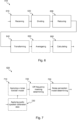
- the step of evaluating 510 comprises the steps detailed in Fig. 6 .
- Evaluating 510 is initiated by the reception 610 of a noise signal, this step is performed by the previously presented analogue to digital conversion module 111 in combination with e.g. the microphone 170.
- the received signal is subjected to the step of dividing 620 the signal into one or more frames which is performed by the frame-by-frame buffers 112 as presented in earlier sections.
- the framed signal is processed by reducing 630 false frequencies and transients using windowing, over-lap and add techniques. Typically, this is performed by a function such as the disclosed windowing, overlap and add function 113.
- the reduced signal is further processed by transforming 640 the frames into the frequency domain using a Fast Fourier Transform by functions, processes and/or devices as disclosed with relation to the Fast Fourier Transform block 114.
- the step of evaluating 510 may comprise the step of averaging 650 the transformed signal. This may be done according to functions presented in relation to the averaging and smoothing function 115.
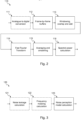
- the step of determining 520 is performed as detailed in Fig. 7 .
- the noise perception model determining 730 is, as mentioned above, performed by functions, modules or blocks implemented in accordance with the noise perception model calculation 123 as presented in earlier sections.
- the step of determining 520 also comprises the step of off frequency masking determining 720 which is performed in accordance with the details given regarding the frequency masking calculation 122.
- the step of determining 520 may comprise the step of applying a noise transfer model 710 which is conducted in line with the description given regarding the noise leakage calculation 121 in previous sections.
- the step of determining 520 may comprise, in some variants, the step of applying 730 a pre-determined audio speaker calibration data. This is preferably done in line with the description given regarding the speaker characteristics profiling module 150 as earlier presented.
- a method for compensating a hearing test is disclosed.
- the hearing test is performed by generating one or more test tones of a number of test tone frequencies.
- the test tones arc presented to the user using e.g. an audio speaker 180.
- the user will indicate perception of the test tone such that a test result comprising intensity levels of hearing for the number of test tone frequencies is provided.
- Based on the test result a hearing profile is created by the hearing test.
- the method comprises the step of acquiring 810 audio speaker calibration data. This data is typically predetermined and more details regarding the speaker calibration data and the compensation are to be found in the section relating to the speaker characteristics profiling module 150.
- Compensating 820 may be done by e.g. the previously presented test tone compensation module 130 and/or the previously presented test result compensation module 160.
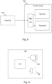
- FIG. 9 a block diagram of a preferred embodiment of an audio speaker assembly 20 is presented.
- the audio speaker assembly 20 is configured to connect to an interface unit 1030 of a computing device 10 such that a compensated hearing test as described in earlier passages of this disclosure is possible to perform.
- the audio speaker assembly 20 comprises a second controller 910, the at least one audio speaker 180 and a second microphone 920.
- the second control unit 910 is operatively connected to the audio speaker 180 and, in some variants, also to the second microphone 920.
- the connection to the interface unit 1030 may be any suitable connection interface and the skilled person will have the knowledge to adapt the disclosed audio speaker assembly 20 such that a suitable operative connection is achieved between the audio speaker assembly 20 and the interface unit 1030 of the computing device 10.
- the second control unit 910 receives instructions from the interface unit 1030 of the computing device 10 and these instructions comprise instruction to do either some of or all of evaluate a noise level, determine a noise perception model based on a noise level and/or compensate at least one of the test result or the test tones using a noise perception model.
- Such data is e.g. raw noise data, evaluated noise level, noise perception model etc. It may be that the data obtained by the second control unit 910 is to be sent back to the interface unit 1030 of the computing device 10 for e.g. further processing, storage, validation etc.
- the execution of the instructions, evaluating a noise level, determining a noise perception model or compensating at least one of the test result or the test tones is performed as outlined in previous sections of this disclosure.
- the computing device 10 is configured, or at least configurable, to be operatively connected to the audio speaker assembly 20 such that a compensated hearing test as presented in earlier sections is possible to perform.
- the computing device 10 comprises the first controller 1010, a first microphone 1020 and the interface unit 1030.
- the first control unit 1010 is configured, or configurable, to operatively connect, via the interface unit 1030, to the second control unit 910 of the audio speaker assembly 20.
- the first control unit 1010 will send instructions to the second control unit 910 comprising instruction to do at least one of presenting one or more test tones of a number of test tone frequencies, evaluate a noise level, determine a noise perception model and/or compensate at least one of the test result or one or more test tones.
- the instructions sent to the second control unit 910 may in some variants comprise the necessary data to execute the requested instructions, examples of data is e.g. raw noise data, evaluated noise level, noise perception model etc.
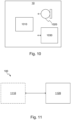
- Fig. 11 presents a block diagram of one embodiment of the system 100 for performing a compensated hearing test according to this disclosure.
- the system 100 comprises a computing device 1110 and an audio speaker assembly 1120.
- the system 100 further comprises at least one control unit, at least one microphone and an audio speaker 180.
- the at least one microphone is used to perceive noise that is sent to the at least one control unit.
- the at least one audio speaker 180 is used for presenting the previously described one or more test tones of a number of test tone frequencies to a user.
- the functions outlined in e.g. Fig. 1b and further detailed with reference to the following Figs. are all possible to be performed by the system 100.
- the computing device 1010 is the only device in the system comprising a control unit and this control unit would be responsible for performing all the functions disclosed.
- a control unit e.g. a mobile phone
- the audio speaker assembly 1020 is e.g. a pair of wired headphones.
- the audio speaker assembly also comprise a control unit but all functions relating to the compensated hearing test are being performed by the computing device 1110.
- An example is a system 100 wherein the computing device 1010 is e.g. a mobile phone and the audio speaker assembly 1020 is e.g. a pair of active wired or wireless headphones such as noise cancelling headphones etc.
- the computing device 1110 is optional and the audio speaker assembly 1020 is solely responsible for performing the compensated hearing test.
- the audio speaker assembly 1120 being a pair of intelligent headphones that can generate test tones and receive user feedback, through e.g. buttons or other means of control, indicative of user perception of the test tones.
- the computing device 1110 of Fig. 11 is the computing device 10 as presented in previous sections and the audio speaker assembly 1120 of Fig. 11 is the audio speaker assembly 20 of previous sections.
Landscapes
- Health & Medical Sciences (AREA)
- Life Sciences & Earth Sciences (AREA)
- Audiology, Speech & Language Pathology (AREA)
- Physics & Mathematics (AREA)
- Engineering & Computer Science (AREA)
- Biomedical Technology (AREA)
- Medical Informatics (AREA)
- Acoustics & Sound (AREA)
- Biophysics (AREA)
- Pathology (AREA)
- Otolaryngology (AREA)
- Heart & Thoracic Surgery (AREA)
- Multimedia (AREA)
- Molecular Biology (AREA)
- Surgery (AREA)
- Animal Behavior & Ethology (AREA)
- General Health & Medical Sciences (AREA)
- Public Health (AREA)
- Veterinary Medicine (AREA)
- Circuit For Audible Band Transducer (AREA)
- Measurement Of Mechanical Vibrations Or Ultrasonic Waves (AREA)
Description
- The present invention relates to hearing test for generating a hearing profile and particularly to hearing tests performed in an uncontrolled environment
- Since the introduction of portable electronic equipment such as the Walkman™ in the late 1970's, the availability and quality of portable audio has been ever improving. With the smartphone, every user of such a device has access to an almost endless supply of music and other audio content. The audio content will typically be experienced through a pair of headphones or other portable speakers.
- The audio content is intended to sound in a specific way, e.g. the author and the producer of the content have a certain idea of how the content should be perceived by a listener. The same can be said with regards to the speakers and the headphone. The designers of those products typically have a vision of how their product should alter the audio content in order to create e.g. a brand specific sound or feeling.
- The way the actual audio content is perceived by a listener will depend greatly on the hearing profile of the listener. Audio and audio playback equipment is designed for a listener having an average hearing profile or a listener having a substantially flat hearing profile. In either way, having the perceived audio compensated for the hearing profile of the listener greatly improves the listening experience.
- The basic concept of compensating audio content based on a hearing profile of a user is known and described in
US2006215844 which relates in general to methods and systems for filtering and amplifying audio signals to improve the listening environment for both normal and hearing-impaired persons.US2006215844 bases the filtering and amplifying of audio signals on a determined hearing profiles of a listener. - One way of performing a hearing test in order to create a hearing profile of a user is to subject the user to audio test tones of different frequencies. The user is requested to indicate if the test tone is perceived and if this is the case, the intensity of the test tone is decreased until the user is unable to perceive the test tone. The lowest intensity where the test tone was perceived by the user will, together with the frequency of test tone, constitute one data point in the hearing profile. This hearing profile may in turn be used to compensate the frequency response of audio such that the audio is compensated for any hearing impairments of the user.
- The determining of the hearing profile will require a silent, or at least quiet surrounding in order to be accurate. Background noise and other forms of audio pollution will affect the hearing profile and may result in an incorrect profile.
-
CN101862195A relates to a circuit for use in hearing tests and assisted hearing, and more particularly to a hearing test and hearing aid system. -
US 2015358745 presents an earpiece for use in conducting a hearing test, a hearing test kit and a method of conducting a hearing test. The earpiece includes a speaker which generates stimuli and a microphone which detects ambient noise. The stimuli generated by the speaker compensates for the ambient noise detected by the microphone. -
US 2014309549 describes a method for testing hearing ability of a used by outputting a first audible tone including a first frequency and recording a first volume adjustment for the first audible tone by the user. Outputting a second audible tone including a second frequency and recording a second volume adjustment for the second audible tone by the user. The method further includes selecting default settings for the first and second signals based on a noise floor proximal the user. -
US 6160893 pertains to an active noise control system for use in testing hearing using a pure tone audiometry testing procedure and employing multiple switching controllers with pre-filtering means. -
US 2018098720 speak of a method and a set of headphones to enable a user of the set of headphones to conduct a self-administered hearing test. - In "Smartphone-Based Hearing Screening in Noisy Environments" by Youngmin et al. 2014, a smartphone automatically measures the environmental noise and provides a hearing threshold shift value to correct the hearing threshold during an ubiquitous hearing test.
- The determining of the hearing profile by performing a hearing test is known. But the prior art fails to disclose how to determine a hearing profile in an uncontrolled environment with stochastic sounds in combination with background noise.
- In view of the above, it is evident that there is room for improvements.
- An object of the present invention is to provide a new type of hearing test which is improved over prior art and which eliminates or at least mitigates the drawbacks discussed above. Another object of the invention is to provide a hearing test performed in an uncontrolled environment from which it is possible to generate an accurate hearing profile. One or more of these objects are achieved by the technique set forth in the appended independent claims with preferred embodiments defined in the dependent claims related thereto.
- According to a first aspect, a method for noise compensating a hearing test performed in an uncontrolled environment is provided. The hearing test being performed by generating one or more test tones of a number of test tone frequencies, presenting, using an audio speaker, said test tones to a user, receiving user input indicative of the users perception of the test tones such that a test result comprising intensity levels of hearing for the number of test tone frequencies is provided, and generating a hearing profile based on the test result. The method comprises evaluating a noise level received from a microphone, determining a noise perception model based on said noise level, and compensating at least one of the test result or said one or more test tones using the noise perception model.
- The step of evaluating the noise perception model comprises calculating a noise power spectrum based on the evaluated noise level. The noise power spectrum comprising noise level for a number of frequency ranges. The noise power spectrum is an efficient, flexible and accurate representation of the evaluated noise level. The number of frequency ranges may be the same as the number of test tone frequencies. This allows for simple and efficient correlation between test tones and frequency ranges and opens up for bandwidth optimization etc.
- The noise perception model further comprises determining off frequency masking between the one or more test tone frequencies and the noise power spectrum for each of the number of frequency ranges. This is beneficial since it allows for accurate compensation of noise when strong off-frequency sounds are perceived.
- In a variant of the method, the audio speaker is comprised in an audio speaker assembly. Having the audio speaker in an assembly allows for a fixed position of the speakers and a more controlled and repeatable hearing test is possible. The noise perception model may further comprise applying a noise transfer model to the noise perception model. The noise transfer model comprises pre-calibrated data related to transfer of external noise into the audio speaker assembly. This is beneficial since it makes for a more accurate noise compensation since the actual noise transferred to the listener is compensated for.
- In a second variant of the method, the method further comprises calculating test signal power adjustment levels for the one or more test tones based on the noise perception model and applying the signal power adjustment levels to the one or more test tones. By compensating the levels of the test signals, the result recorded will be accurate regardless of the environment, also, it is a simple and straight forward compensation that consumes little computing power.
- In a third variant of the method, the method further comprises calculating test result adjustment levels for the number of test tone frequencies based on the noise perception model and applying the test result adjustment levels to the test result. By applying the signal to the test result, the result recorded will be accurate regardless of the environment. Also, it is a simple and straight forward compensation that consumes little computing power.
- In a fourth variant of the method, evaluating the noise level further comprises, receiving a noise signal, dividing the noise signal into one or more frames, reducing false frequencies and transients in the one or more frames using windowing, over-lap and add techniques and transforming the one or more frames into a frequency domain using a Fast Fourier Transform. This is beneficial since the frequency representation offered by the FFT will be clean, stable and substantially free from unwanted artefacts.
- According to the invention, the noise perception model is updated substantially continuously during the duration of the hearing test by substantially continuously evaluating the noise level. By running the method frequently, impulse noise and fast changes in noise are compensated for.
- In a fifth variant of the method, determining the noise perception model further comprises applying a pre-determined audio speaker calibration data comprising a frequency transfer function of the audio speaker. This is useful since it allows for the profile of the audio speakers to be unaffected by the compensation of the hearing test.
- According to a second aspect, a method for compensating a hearing test is provided. The hearing test being performed by generating one or more test tones of a number of test tone frequencies, presenting, using an audio speaker, said test tones to a user, receiving user input indicative of the users perception of the test tones such that a test result comprising intensity levels of hearing for the number of test tone frequencies is provided, and generating a hearing profile based on the test result. The method comprises acquiring a pre-determined audio speaker calibration data comprising a frequency transfer function of the audio speaker, and compensating at least one of the test result or said one or more test tones using the pre-determined audio speaker calibration data.
- According to a third aspect, an audio speaker assembly configured to be operatively connected to an interface unit of a computing device for performing a compensated hearing test according to the first aspect of the invention is provided. The computing device further comprises a first control unit and a first microphone. The audio speaker assembly comprises at least one audio speaker, a second microphone and a second control unit operatively connected to said at least one audio speaker. The second control unit is configured to control the at least one audio speaker to present one or more test tones of a number of test tone frequencies. The second control unit is further configured to, based on instructions received from the first control unit, perform at least one of, evaluate a noise level, perceived by the first and/or second microphone, determine a noise perception model based on said noise level, or compensate at least one of the test result or said one or more test tones using the noise perception model.
- In a first variant of the audio speaker assembly the audio speaker assembly is further configured to perform the method of the second aspect.
- According to a fourth aspect, a computing device configured to be operatively connected to an audio speaker assembly for performing a compensated hearing test according to the method of the first aspect is provided. The audio speaker assembly comprises at least one audio speaker, a second microphone and a second control unit. The computing device comprises an interface unit, a first microphone and a first control unit. The first control unit is configured to instruct the second control unit to, via the one or more audio speakers, present one or more test tones of a number of test tone frequencies. The first control unit is further configured to perform at least one of: evaluate a noise level, perceived by the first and/or second microphone, determine a noise perception model based on said noise level, or compensate at least one of the test result or said one or more test tones using the noise perception model.
- In a first variant of the computing device, the computing device is further configured to perform the method of the second aspect.
- According to a fifth aspect, a system for performing a compensated hearing test is provided. The hearing test being performed by allowing a user to indicate perception of one or more test tones of a number of test tone frequencies. The system comprising a computing device comprising an interface unit, a first microphone and a first control unit, an audio speaker assembly comprising at least one audio speaker, a second microphone and a second control unit. The first control unit is operatively connected to the second control unit and wherein the audio speaker assembly is the audio speaker assembly according to any of the third aspect or the computing device is the computing device according to any of the fourth aspect.
- Embodiments of the invention will be described in the following; references being made to the appended diagrammatical drawings which illustrate non-limiting examples of how the inventive concept can be reduced into practice.
-
Fig. 1a is a system for performing a compensated hearing test in an uncontrolled environment according to one embodiment, -
Fig. 1b is a block diagram for performing a compensated hearing test in an uncontrolled environment; -
Fig. 2 is a block diagram of a noise evaluation module according to some embodiments; -
Fig. 3 is a block diagram of a noise perception model determination module according to some embodiments; -
Fig. 4a is a graph illustrating the concept of off-frequency masking, -
Fig. 4b is a graph illustrating the concept of off-frequency masking; -
Fig. 5 is a block diagram illustrating a method for noise compensating a hearing test performed in an uncontrolled environment according to some embodiments; -
Fig. 6 is a detailed block diagram of the method step of evaluating a noise level according to some embodiments; -
Fig. 7 is a detailed block diagram of the method step of determining a noise perception model according to some embodiments; -
Fig. 8 is a block diagram illustrating a method for noise compensating a hearing test performed in an uncontrolled environment according to some embodiments; -
Fig. 9 is a block diagram of an audio speaker assembly according to some embodiments; -
Fig. 10 is a block diagram of a computing device according to some embodiments; and -
Fig. 11 is a block diagram of a system for performing a compensated hearing test according to some embodiments. - Hereinafter, certain embodiments will be described more fully with reference to the accompanying drawings. The invention may, however, be embodied in many different forms and should not be construed as limited to the embodiments set forth herein; rather, these embodiments are provided by way of example so that this disclosure will be thorough and complete, and will fully convey the scope of the invention, such as it is defined in the appended claims, to those skilled in the art.
- Sound pollution is an increasing problem and fewer and fewer places around the globe are considered silent. Any urban environment is subject to sounds from e.g. vehicles and transportation systems, environment control of buildings, neighbors etc. Some of these sounds exhibit some form of periodicity and repeatability in frequency behavior and intensity, others are completely stochastic, asynchronous and will occur once, such as particularly a car horn sounding in an intersection. Performing a hearing test in such an uncontrolled environment, as will be disclosed in this specification, has been made possible by inventive thinking of the inventors behind the solutions presented. A compensated hearing test, as will be disclosed in the coming sections, may be used to generate a hearing profile associated with a user or a listener such that the hearing profile may be used to compensate audio or audio playback equipment for any hearing impairments of the user. The hearing profile generated by some embodiments of this invention will make it possible to generate a generic hearing profile associated with one specific user. The hearing profile being generic in the sense that it describes the hearing profile of the user without any effects from the equipment used to generate the hearing profile. This enables the compensation and personalization of audio in any audio playback equipment even if the hearing test is done at a different location with different equipment. One non-limiting example where a generic hearing profile is beneficial is in an audio system for a vehicle, e.g. car, truck, bus, etc. It is challenging to generate the hearing profile in the vehicle, due to e.g. the difficulties associated with isolating the hearing of the left ear from the right ear.
- Hearing impairment is, in this disclosure, meant as comprising any common deviation in perception of audio compared to a hearing profile of a person with perfect hearing. In other words, deafness or severe hearing disabilities is not considered a common deviation in perception of audio compared to a hearing profile of a person with perfect hearing.
- With reference to
Fig. 1a , asystem 100 for performing a compensated hearing test in an uncontrolled environment is shown. Thesystem 100 comprises anaudio speaker assembly 20, shown inFig. 1a as a pair of headphones but it may very well be anysuitable speaker assembly 20, as will be exemplified throughout this disclosure. Since the position of the listener in relation to theaudio speaker 180 will affect the hearing profile, fixed positionaudio speaker assemblies 20 are preferred but this invention is not limited to such devices. Fixedposition speaker assemblies 20 are here referred to asaudio speaker assemblies 20 arranged in e.g. headphones or headsets in any size, shape or form. - The
system 100 as illustrated inFig. 1a , comprises acomputing device 10, e.g. a mobile phone, PDA, laptop, smart watch or any suitable portable or stationary electronic equipment and anaudio speaker assembly 20, e.g. a pair of headphones, a headset etc. Thecomputing device 10 is operatively connected to theaudio speaker assembly 20 via acommunications interface 30. Thecommunications interface 30 may be a wired or a wireless interface. The wireless interface may be any suitable interface e.g. Bluetooth, WIFI, cellular etc. Thecomputing device 10 comprises an interface unit configured to be operatively connected to theaudio speaker assembly 20 via thecommunications interface 30. Thecomputing device 10 further comprises a first interface unit and a first microphone operatively connected to a first controller. The audio speaker assembly comprises at least oneaudio speaker 180 and a second control unit operatively connected to the audio speaker(s). Theaudio speaker assembly 20 may further comprise a second microphone. - With reference to
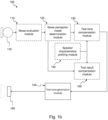
Fig. 1b , a block diagram of thesystem 100 for performing a compensated hearing test in an uncontrolled environment is shown. Thesystem 100 comprises amicrophone 170 that is operatively connected to anoise evaluation module 110 which in turn operatively connects to a noise perceptionmodel determination module 120. A testtone compensation module 130 receives its inputs from at least one of the noise perceptionmodel determination module 120 and a speakercharacteristics profiling module 150. Alternatively, or additionally to the test tone compensation module 130 a testresult compensation module 160 receives its input from at least one of the noise perceptionmodel determination module 120 and the speakercharacteristics profiling unit 150. The testtone compensation module 130 is operatively connected to a testtone generation module 140 which operatively connects to anaudio speaker 180. Theaudio speaker 180 is typically comprised in anaudio speaker assembly 20. Themodules system 100 will be explained in further detail in the coming section and it should be emphasized that not allmodules microphone 170 may be omitted from some embodiments. It will be clear from the coming sections that themodules - The following disclosure may detail the
modules modules modules particular module - The
noise evaluation module 110, detailed inFig. 2 , measures and evaluates a signal corresponding to a sound perceived by themicrophone 170. The sound perceived by themicrophone 170 may be provided to thenoise evaluation module 110 in digital or analogue form. If the sound is provided in analogue form, the signal is sampled using e.g. an analogue todigital converter 111. The digital signal will have a sample rate Rs and each sample will be represented by a number of bits. The digital signal is divided into frames by buffering the samples in frame-by-frame buffers 112. The frames will contain N samples and the frame rate RF can consequently be calculated according to Eqn. 1.
- The frames may be of any length and the frame length affects the latency of the system. The latency will be manifested as how fast changes in sound can be tracked and changed. A typical frame length consists of 256 samples which corresponds to just under 6 ms of data in a 44100 Hz sampling audio system.
- The frames are likely to comprise samples of signals of several different frequencies and the frequencies represented in a frame are unlikely an integer number of cycles of each frequency. These discontinuities in the frames give rise to spectral leakage when converted to a frequency domain and in order to reduce these effects, the frames are windowed. Windowing consists of multiplying samples of the frame by a window of the same length as the frame, where the amplitude of the widow varies smoothly and gradually towards zero at the edges of the window. The consequence is that the discontinuities, occurring at the edge of the frame, are reduced to zero which result in a frame that can be regarded as continuous. The windowing function reduces the energy of the frame and an overlap-and-add function is used in order to compensate for this loss of energy. The overlap-and-add function convolutes a current frame with a number of previous frames. The overlap-and-add functionality together with the windowing function is performed by the windowing, overlap-and-
add function 113. There are numerous different windowing functions possible with e.g. varying roll-off rate and side lobe levels, typically in this disclosure, a Hamming or Hanning window may be suitable but these windowing functions should not be considered limiting. Also, the overlap-and-add function is configurable in e.g. the amount of overlap chosen, typically an overlap between 50 and 75% of the previous frame may be suitable but also this should be considered as a non-limiting example. - These frames are transformed into the frequency domain using e.g. a Fast Fourier Transform,
FFT function 114 providing a frequency and phase representation of the audio. The frequency resolution of the frequency and phase representation of the audio will be dependent on both the frame length and the order of the FFT. In a non-limiting example, the FFT size is 256 which will result in a frequency resolution of half the FFT size, i.e. 128 frequency components or bins. Each bin will have a bandwidth of equal to the Nyquist sampling rate, i.e. half the sample rate of the audio signal, divided by the total number of bins. In the example with 44100 Hz sample rate and an FFT size of 256, the bandwidth of each bin will be 44100/2/128 which comes out as just above 170 Hz. - The frequency bins output from the
FFT function 114 may vary and fluctuate between calculations. In order to reduce these fluctuations and find a more steady state of the signal, the signals are passed through an averaging and smoothingfunction 115. The averaging and smoothing may be performed by e.g. utilizing a sliding window function with or without weighting. A sliding window of a length N may be utilized to calculate the average across the current and the N-1 last samples. Alternatively or additionally, weighting may be applied where, typically, older samples arc multiplied with a lower factor compared to later samples. As a non-limiting example, consider two samples Sn and Sn-1 being weighted by a weighting factor wf of 0.1, this would result in an average S according S=Sn ∗(1-wf)+ Sn-1 ∗wf. This averaging is in effect a low pass filter and will consequently reduce unwanted fluctuations and reduce possible false components of the signal. The skilled person will understand how to dimension averaging and smoothing parameters in order to achieve a suitable tradeoff between bandwidth and signal smoothness. - The comparably smooth signal being output from the averaging and smoothing
function 115 is in turn fed to a spectralpower calculation function 116. The spectralpower calculation function 116 calculates the power spectrum of the signal for each bin by e.g. calculating the absolute value of the complex signal calculated by theFFT function 114, i.e. the magnitude of the signal. - The calculated power spectrum is fed to the noise perception
model determination module 120, detailed inFig. 3 , which uses the received noise spectrum to calculate a noise perception model using a noise perceptionmodel calculation function 123. The noise perceptionmodel calculation function 123 calculates control values that may be used either to compensate the test tones using the testtone compensation module 130 and/or to compensate the test result using the testresult compensation module 160. Basically, the control values calculated by the noise perceptionmodel calculation function 123 relates to an inverse of a perceived noise. The perceived noise may be the noise power spectrum as output from the spectralpower calculation function 116. Alternatively, the perceived noise may be the noise power spectrum as output from the spectralpower calculation function 116 modified by a noiseleakage calculation function 121 and/or a frequency maskingcalculation function 122. - The received noise, as acquired by the
microphone 170, is typically acquired at a position proximate to, but outside of, theaudio speaker assembly 20. This means that the noise acquired by the microphone may be of a different level than the noise perceived by the listener due to e.g. noise attenuation of theaudio speaker assembly 20. The noiseleakage calculation function 121 compensates the noise power spectrum depending on how noise is transported from the outside of theaudio speaker assembly 20, e.g. a pair of headphones, headset etc., to the ear of the listener. Basically this means describing how sounds of different frequencies are attenuated by theaudio speaker assembly 20 and this may vary greatly depending on theaudio speaker assembly 20. Many factors influence the noise leakage calculation e.g. the design of theaudio speaker assembly 20 being e.g. an over-ear, on-ear or in-ear headset. The noise leakage of a particular speaker assembly is typically characterized once per unit, model, series, group of models, group of series or brand ofaudio speaker assemblies 20 and is stored in such a way that it is accessible and available to thenoise evaluation module 121. The noise leakage may be characterized by utilizing two microphones. One microphone may be arranged in a position inside theaudio speaker assembly 20 such that its perception of sound would be similar to that of the user of theaudio speaker assembly 20. Another microphone may be arranged outside of theaudio speaker assembly 20 and the noise leakage is characterized by the difference in sound pressure perceived by the two microphones for different frequencies. The noise leakage may be characterized for a number of different frequencies and also at different sound pressure levels. Since the noise leakage may be characterized at both different frequencies and at different sound pressures, the characterization may be represented in a noise leakage table. The noiseleakage calculation function 121 module would, for each iteration depending on e.g. the power spectral density of a particular bin of the received noise spectrum, select appropriate data from the noise leakage table and compensate the received noise spectrum accordingly. - According to the invention, a function in the noise perception
model determination module 120 is the frequency maskingcalculation function 122. The frequency maskingcalculation function 122 compensates the received noise spectrum for auditory masking occurring due to off-frequency masking. Simply put, this means that a sound at a first frequency may reduce the possibility to perceive sound at a second frequency, it can be compared to e.g. blocking and selectivity in radio electronics. The off-frequency masking is well described in literature with curves describing how sounds of different frequencies and intensity are masked by sounds at other frequencies and intensities. The effect of off-frequency masking is used in the compression algorithms for audio e.g. the Moving Picture Experts Group Layer-3 Audio, MP3. In order for off-frequency masking to occur, the off-frequency signal has to have a higher sound pressure level than the wanted sound. This means that the frequency maskingcalculation function 122 may be applied adaptively depending on the received noise spectrum and also on the expected sound pressure of the test tone to be generated. In other words, the frequency maskingcalculation function 122 is only needed if there are frequency bins surrounding a frequency bin currently targeted for the hearing test that have higher sound pressure level than the frequency bin of interest. - A non-limiting example is here presented with reference to
Figs. 4a and 4b . InFig. 4a , a received noise spectrum represented in five bins A-E is illustrated. Bin B has a comparably higher power spectral density compared to the other bins A, C, D, E and bin B may mask the other bins A, C, D, E. For completeness, the form of auditory masking the received noise power in bin B will have on frequencies falling within the bandwidth of bin B is referred to as on-frequency masking. The off-frequency masking effect bin B has on the other bins A, C, D, E is shown inFig. 4b where the masking effect is illustrated as an addition in the power spectral density of the other bins A, C, D, E. - The noise perception
model calculation function 123 uses the received noise power, optionally subject to the noiseleakage calculation function 121 and/or the frequency masking calculation function to generate a noise perception model. The noise perception model comprises, for each bin, a compensation level indicative of how a test tone or test result, falling within a corresponding bin should be compensated. Typically, a test tone or its corresponding test result is increased by the received noise power, optionally subject to the noiseleakage calculation function 121 and/or the frequency maskingcalculation function 122 multiplied with a scaling factor. The scaling factor may be determined empirically and may be the same factor for all of the bins or some of the bins. The noise perception model is provided as an input to the testtone compensation module 130 and/or the testresult compensation module 160. - The speaker
characteristics profiling module 150 is an optional module, function or unit that calculates the effect of anaudio speaker assembly 20. Many manufacturers ofaudio speaker assemblies 20 andaudio speakers 180 have models with characteristic sounds or have a particular sound that they would like to associate with their brand. Someaudio speaker assemblies 20 may be designed with characteristics specific to particular styles of music such as rock. Anaudio speaker assembly 20 with characteristics aimed at providing a rock-like sound may have a frequency response that is flat in the middle regions and amplified or increased in the lower and higher regions. When performing a hearing test in order to compensate sound for the hearing profile of the listener, the effect of theaudio speaker assembly 20 used when performing the hearing test to generate the hearing profile will be compensated for. The hearing test will aim at generating a substantially flat which means that the frequency response associated with anaudio speaker assembly 20 used when performing a hearing test will be compensated for by the hearing test. This means that designed characteristics of anaudio speaker assembly 20 will be removed and this may not be a desired effect. The speakercharacteristics profiling module 150 has access to a headset calibration data. The headset calibration data is provided pre-calculated and pre-stored in such a manner that it is accessible by the speakercharacteristics profiling module 150. The headset calibration data may be e.g. stored in a local memory, accessible from a cloud service, provided by a user etc. The headset calibration data is typically generated by feeding anaudio speaker assembly 20 with white noise or several different frequencies one by one and measuring the auditory response from theaudio speaker assembly 20. The headset calibration data may be characterized by the difference between the sound pressure level of the sound fed to theaudio speaker 180 and the sound pressure level as measured as the auditory response from theaudio speaker 180. The speakercharacteristics profiling module 150 uses the headset calibration data to generate a speaker characteristic profile which may be the inverse of the headset calibration data that may further be scaled by a factor. Typically, if the headset calibration data indicate a reduction of sound pressure of a particular magnitude at a particular frequency, the speaker characteristic profile comprises an increase of substantially the same magnitude at substantially the same frequency. The speaker characteristic profile is provided as an optional input to the testtone compensation module 130 and/or the testresult compensation module 160. - The test
tone compensation module 130 receives input from at least one of the noise perceptionmodel determination module 120 or from the speakercharacteristics profiling module 150 and uses these inputs to form a test tone compensation that is provided to the testtone generation module 140. The test tone compensation may comprise e.g. factors or compensation values each associated directly with the different frequencies of the test tones. It may be that the output of the speakercharacteristics profiling module 150 is in a different format to the output from the noise perceptionmodel determination module 120 and/or the desired input of the testtone generation module 140. The testtone compensation module 130 converts, if necessary, its inputs to the desired format of the test tone generation module. The resolution in frequency or amplitude may differ between either the input and/or the output and the testtone compensation module 130 scales the inputs to correspond to the desired input of the testtone generation module 140. - The test
result compensation module 160 is an alternative or addition to the testtone compensation module 130. The testresult compensation module 160 receives inputs from at least one of the noise perceptionmodel determination module 120 or the speakercharacteristics profiling module 150. These inputs are used to compensate the result of the hearing test and that may be done e.g. continuously as the test progresses, at the end of the test or at the certain steps of the hearing test such as upon finalization of one particular test tone. - The test
tone generation module 140 is the unit, module, device or function responsible for generating the test tones that are provided to theaudio speaker 180. The testtone generation module 140 receives input, the test tone compensation, from the testtone compensation module 130 and applies the test tone compensation to the test tone to be generated. Typically this may imply increasing the sound pressure of a test tone in the presence of ambient noise and perhaps decreasing a test tone to compensate for an amplification of anaudio speaker assembly 20. In either way, the test tone compensation comprises the necessary data to perform the compensation of the test tone in order to provide a test tone of desired amplitude and frequency to thespeaker assembly 180. - As is apparent from the disclosure so far, the combination of the functions, modules overviewed in
Fig. 1 may be done in many different ways. The following sections will detail some of these combinations, but it should be mentioned that all suitable combinations are to be considered covered although not explicitly disclosed. - A preferred embodiment of a method for noise compensating a hearing test performed in an uncontrolled environment is presented in
Fig. 5 . The method may be performed by e.g. thesystem 100 presented inFig. 1b . The hearing test is performed by generating, by e.g. a testtone generation module 140, one or more test tones and providing the one or more test tones to e.g. anaudio speaker 180, so that they can be presented to a user. The user indicates perception of the audio tones by providing feedback that is communicated to the testtone generation module 140 so that the intensity of the test tone associated with the feedback can be adjusted in order to find the hearing threshold of the user at that frequency. The result of the hearing test will comprise a number of intensity levels of hearing, typically one per test tone frequency, and a hearing profile can be generated from the test result. The method comprises evaluating 510 a noise level, which may be done by the previously presented noiselevel evaluation module 110 receiving noise from amicrophone 170. Determining 520, by e.g. the noise perceptionmodel calculation module 123 known from previous section, a noise perception model based on the evaluated noise level. The method further comprises compensating 530, based on the noise perception model, either or both of the test result and the one or more test tones. Compensating 530 may be done by e.g. the previously presented testtone compensation module 130 and/or the previously presented testresult compensation module 160. - The step of evaluating 510 may in some variants of the embodiment comprise the step of calculating 660 a noise power spectrum. This is performed by a suitable function, e.g. the presented spectral
power calculation function 116. - In further variants, the step of evaluating 510 comprises the steps detailed in
Fig. 6 . Evaluating 510 is initiated by thereception 610 of a noise signal, this step is performed by the previously presented analogue todigital conversion module 111 in combination with e.g. themicrophone 170. The received signal is subjected to the step of dividing 620 the signal into one or more frames which is performed by the frame-by-frame buffers 112 as presented in earlier sections. The framed signal is processed by reducing 630 false frequencies and transients using windowing, over-lap and add techniques. Typically, this is performed by a function such as the disclosed windowing, overlap and addfunction 113. The reduced signal is further processed by transforming 640 the frames into the frequency domain using a Fast Fourier Transform by functions, processes and/or devices as disclosed with relation to the Fast Fourier Transform block 114. Optionally, the step of evaluating 510 may comprise the step of averaging 650 the transformed signal. This may be done according to functions presented in relation to the averaging and smoothingfunction 115. - In some variants of the method, the step of determining 520 is performed as detailed in
Fig. 7 . The noise perception model determining 730 is, as mentioned above, performed by functions, modules or blocks implemented in accordance with the noiseperception model calculation 123 as presented in earlier sections. According to the invention, the step of determining 520 also comprises the step of off frequency masking determining 720 which is performed in accordance with the details given regarding thefrequency masking calculation 122. Further to this variant, or as a separate variant, the step of determining 520 may comprise the step of applying anoise transfer model 710 which is conducted in line with the description given regarding thenoise leakage calculation 121 in previous sections. The step of determining 520 may comprise, in some variants, the step of applying 730 a pre-determined audio speaker calibration data. This is preferably done in line with the description given regarding the speakercharacteristics profiling module 150 as earlier presented. - In another preferred embodiment, presented in
Fig. 8 , a method for compensating a hearing test is disclosed. The hearing test is performed by generating one or more test tones of a number of test tone frequencies. The test tones arc presented to the user using e.g. anaudio speaker 180. The user will indicate perception of the test tone such that a test result comprising intensity levels of hearing for the number of test tone frequencies is provided. Based on the test result a hearing profile is created by the hearing test. The method comprises the step of acquiring 810 audio speaker calibration data. This data is typically predetermined and more details regarding the speaker calibration data and the compensation are to be found in the section relating to the speakercharacteristics profiling module 150. Compensating 820 may be done by e.g. the previously presented testtone compensation module 130 and/or the previously presented testresult compensation module 160. - In
Fig. 9 , a block diagram of a preferred embodiment of anaudio speaker assembly 20 is presented. Theaudio speaker assembly 20 is configured to connect to aninterface unit 1030 of acomputing device 10 such that a compensated hearing test as described in earlier passages of this disclosure is possible to perform. Theaudio speaker assembly 20 comprises asecond controller 910, the at least oneaudio speaker 180 and asecond microphone 920. Thesecond control unit 910 is operatively connected to theaudio speaker 180 and, in some variants, also to thesecond microphone 920. The connection to theinterface unit 1030 may be any suitable connection interface and the skilled person will have the knowledge to adapt the disclosedaudio speaker assembly 20 such that a suitable operative connection is achieved between theaudio speaker assembly 20 and theinterface unit 1030 of thecomputing device 10. Thesecond control unit 910 receives instructions from theinterface unit 1030 of thecomputing device 10 and these instructions comprise instruction to do either some of or all of evaluate a noise level, determine a noise perception model based on a noise level and/or compensate at least one of the test result or the test tones using a noise perception model. The data necessary to execute the steps, if thesecond controller 910 is not instructed to obtain, by e.g. calculation, evaluation, measurement etc., the data, will be received from theinterface unit 1030. Such data is e.g. raw noise data, evaluated noise level, noise perception model etc. It may be that the data obtained by thesecond control unit 910 is to be sent back to theinterface unit 1030 of thecomputing device 10 for e.g. further processing, storage, validation etc. The execution of the instructions, evaluating a noise level, determining a noise perception model or compensating at least one of the test result or the test tones is performed as outlined in previous sections of this disclosure. - With reference to
Fig. 10 , which illustrates a block diagram of thecomputing device 10, a preferred embodiment of thecomputing device 10 will be presented. Thecomputing device 10 is configured, or at least configurable, to be operatively connected to theaudio speaker assembly 20 such that a compensated hearing test as presented in earlier sections is possible to perform. Thecomputing device 10 comprises thefirst controller 1010, afirst microphone 1020 and theinterface unit 1030. Thefirst control unit 1010 is configured, or configurable, to operatively connect, via theinterface unit 1030, to thesecond control unit 910 of theaudio speaker assembly 20. Thefirst control unit 1010 will send instructions to thesecond control unit 910 comprising instruction to do at least one of presenting one or more test tones of a number of test tone frequencies, evaluate a noise level, determine a noise perception model and/or compensate at least one of the test result or one or more test tones. The instructions sent to thesecond control unit 910 may in some variants comprise the necessary data to execute the requested instructions, examples of data is e.g. raw noise data, evaluated noise level, noise perception model etc. -
Fig. 11 presents a block diagram of one embodiment of thesystem 100 for performing a compensated hearing test according to this disclosure. Thesystem 100 comprises acomputing device 1110 and anaudio speaker assembly 1120. Thesystem 100 further comprises at least one control unit, at least one microphone and anaudio speaker 180. The at least one microphone is used to perceive noise that is sent to the at least one control unit. The at least oneaudio speaker 180 is used for presenting the previously described one or more test tones of a number of test tone frequencies to a user. The functions outlined in e.g.Fig. 1b and further detailed with reference to the following Figs. are all possible to be performed by thesystem 100. - In one variant, the
computing device 1010 is the only device in the system comprising a control unit and this control unit would be responsible for performing all the functions disclosed. Such a system is exemplified with thecomputing device 1010 being e.g. a mobile phone and theaudio speaker assembly 1020 is e.g. a pair of wired headphones. - In another variant, the audio speaker assembly also comprise a control unit but all functions relating to the compensated hearing test are being performed by the
computing device 1110. An example is asystem 100 wherein thecomputing device 1010 is e.g. a mobile phone and theaudio speaker assembly 1020 is e.g. a pair of active wired or wireless headphones such as noise cancelling headphones etc. - In another variant, the
computing device 1110 is optional and theaudio speaker assembly 1020 is solely responsible for performing the compensated hearing test. This is exemplified with theaudio speaker assembly 1120 being a pair of intelligent headphones that can generate test tones and receive user feedback, through e.g. buttons or other means of control, indicative of user perception of the test tones. - From the presentation above of the two extreme variants of the
system 100, one where the complete compensated hearing test is performed by thecomputing device 1110 and the other where the complete compensated hearing test is performed by theaudio speaker assembly 1120, it is clear that eitherdevice particular device devices system 100. - However, in a preferred embodiment of the
system 100 thecomputing device 1110 ofFig. 11 is thecomputing device 10 as presented in previous sections and theaudio speaker assembly 1120 ofFig. 11 is theaudio speaker assembly 20 of previous sections.
Claims (13)
- A method for noise compensating a hearing test performed in an uncontrolled environment, the hearing test being performed by generating one or more test tones of a number of test tone frequencies, presenting, using an audio speaker (180), said test tones to a user, receiving user input indicative of the users perception of the test tones such that a test result comprising intensity levels of hearing for the number of test tone frequencies is provided, and generating a hearing profile based on the test result, wherein the method comprises:evaluating (510) a noise level received from a microphone (170) and calculating (660) a noise power spectrum based on the evaluated noise level, the noise power spectrum comprising noise level for a number of frequency ranges,determining (520) a noise perception model based on said noise level and off frequency masking (122) between the one or more test tone frequencies and the noise power spectrum for each of the number of frequency ranges, wherein the noise perception model is updated substantially continuously during the duration of the hearing test by substantially continuously evaluating the noise level andcompensating (530) the test result and said one or more test tones using the noise perception model.
- The method according to claim 1, wherein the number of frequency ranges is the same as the number of test tone frequencies.
- The method according any of the preceding claims, wherein the audio speaker (180) is comprised in an audio speaker assembly (20).
- The method according to claim 3, wherein the noise perception model further comprises applying a noise transfer model (710) to the noise perception model, wherein the noise transfer model comprises pre-calibrated data related to transfer of external noise into the audio speaker assembly (20).
- The method according to any of the preceding claims, wherein the method further comprises calculating test signal power adjustment levels for the one or more test tones based on the noise perception model and applying the signal power adjustment levels to the one or more test tones.
- The method according to any of the preceding claims, wherein the method further comprises calculating test result adjustment levels for the number of test tone frequencies based on the noise perception model and applying the test result adjustment levels to the test result.
- The method according any of the preceding claims, wherein evaluating (510) the noise level further comprises,receiving (610) a noise signal,dividing (620) the noise signal into one or more frames,reducing (630) false frequencies and transients in the one or more frames using windowing, over-lap and add techniques,transforming (640) the one or more frames into a frequency domain using a Fast Fourier Transform.
- The method according to any of the preceding claims, wherein determining (520) the noise perception model further comprises applying (730) a pre-determined audio speaker calibration data comprising a frequency transfer function of the audio speaker (180).
- An audio speaker assembly (20) configured to be operatively connected to an interface unit (1030) of a computing device (10) for performing a compensated hearing test according to the method of any of the claims 1 to 8, wherein the computing device (10) further comprises a first control unit (1010) and a first microphone (1020), wherein the audio speaker assembly (20) comprises at least one audio speaker (180), a second microphone (920) and a second control unit (910) operatively connected to said at least one audio speaker (180), wherein the second control unit (910) is configured to control the at least one audio speaker (180) to present one or more test tones of a number of test tone frequencies, and
wherein the second control unit (910) is further configure to, based on instructions received from the first control unit (1010), perform:substantially continuously during the duration of the hearing test, evaluate a noise level, perceived by the first and/or second microphone (920, 1020) and calculate a noise power spectrum based on the evaluated noise level, the noise power spectrum comprising noise level for a number of frequency ranges,determine a noise perception model based on said noise level and off frequency masking (122) between the one or more test tone frequencies and the noise power spectrum for each of the number of frequency ranges, wherein the noise perception model is updated substantially continuously during the duration of the hearing test by substantially continuously evaluating the noise level, orcompensate the test result and said one or more test tones using the noise perception model. - The audio speaker assembly (20) according to claim 9, wherein the second control unit (910) is further configure to, based on instructions received from the first control unit (1010):acquire a pre-determined audio speaker calibration data comprising a frequency transfer function of the audio speaker (180),compensate (820) at least one of the test result or said one or more test tones using the pre-determined audio speaker calibration data.
- A computing device (10) configured to be operatively connected to an audio speaker assembly (20) for performing a compensated hearing test according to the method of any of the claims 1 to 8, the audio speaker assembly (20) comprising at least one audio speaker (180), a second microphone (920) and a second control unit (910), wherein the computing device (10) comprises:an interface unit (1030), a first microphone (1020) and a first control unit (1010);wherein the first control unit (1010) is configured to instruct the second control unit (910) to, via the one or more audio speakers (180), present one or more test tones of a number of test tone frequencies, andwherein the first control unit (1010) is further configured to perform:substantially continuously during the duration of the hearing test, evaluate a noise level, perceived by the first and/or second microphone (920, 1020),determine a noise perception model based on said noise level and off frequency masking (122) between the one or more test tone frequencies and the noise power spectrum for each of the number of frequency ranges, wherein the noise perception model is updated substantially continuously during the duration of the hearing test by substantially continuously evaluating the noise level, orcompensate the test result and said one or more test tones using the noise perception model.
- The computing device (10) according to claim 11, wherein the computing device (10) is further configured to:acquire a pre-determined audio speaker calibration data comprising a frequency transfer function of the audio speaker (180),compensate (820) at least one of the test result or said one or more test tones using the pre-determined audio speaker calibration data.
- A system (100) for performing a compensated hearing test, the hearing test being performed by allowing a user to indicate perception of one or more test tones of a number of test tone frequencies, the system (100) comprising:a computing device (10) comprising an interface unit (1030), a first microphone (1020) and a first control unit (1010),an audio speaker assembly (20) comprising at least one audio speaker (180), a second microphone (920) and a second control unit (910), whereinthe first control unit (1010) is operatively connected to the second control unit (910) and wherein the audio speaker assembly (20) is the audio speaker assembly (20) according to any of the claims 9 or 10 or the computing device (10) is the computing device (10) according to any of the claims 11 or 12.
Priority Applications (4)
| Application Number | Priority Date | Filing Date | Title |
|---|---|---|---|
| EP18215560.6A EP3669780B1 (en) | 2018-12-21 | 2018-12-21 | Methods, devices and system for a compensated hearing test |
| CN201980082901.0A CN113164102B (en) | 2018-12-21 | 2019-12-20 | Method, device and system for compensating hearing test |
| TW108146952A TWI832942B (en) | 2018-12-21 | 2019-12-20 | Methods, devices and system for a compensated hearing test |
| PCT/EP2019/086628 WO2020127939A1 (en) | 2018-12-21 | 2019-12-20 | Methods, devices and system for a compensated hearing test |
Applications Claiming Priority (1)
| Application Number | Priority Date | Filing Date | Title |
|---|---|---|---|
| EP18215560.6A EP3669780B1 (en) | 2018-12-21 | 2018-12-21 | Methods, devices and system for a compensated hearing test |
Publications (3)
| Publication Number | Publication Date |
|---|---|
| EP3669780A1 EP3669780A1 (en) | 2020-06-24 |
| EP3669780C0 EP3669780C0 (en) | 2023-10-04 |
| EP3669780B1 true EP3669780B1 (en) | 2023-10-04 |
Family
ID=64959160
Family Applications (1)
| Application Number | Title | Priority Date | Filing Date |
|---|---|---|---|
| EP18215560.6A Active EP3669780B1 (en) | 2018-12-21 | 2018-12-21 | Methods, devices and system for a compensated hearing test |
Country Status (4)
| Country | Link |
|---|---|
| EP (1) | EP3669780B1 (en) |
| CN (1) | CN113164102B (en) |
| TW (1) | TWI832942B (en) |
| WO (1) | WO2020127939A1 (en) |
Families Citing this family (9)
| Publication number | Priority date | Publication date | Assignee | Title |
|---|---|---|---|---|
| CN112190259B (en) * | 2020-09-10 | 2024-06-28 | 北京济声科技有限公司 | Method for testing sound source positioning capability, tester terminal and subject terminal |
| WO2022164423A1 (en) * | 2021-01-26 | 2022-08-04 | Hewlett-Packard Development Company, L.P. | Audio device calibration |
| CN115209292A (en) * | 2021-04-14 | 2022-10-18 | Oppo广东移动通信有限公司 | Audio signal compensation method and device, earphone and storage medium |
| DE102021208735B3 (en) * | 2021-08-10 | 2022-11-17 | Sivantos Pte. Ltd. | Method for creating an audiogram of a test subject using a hearing instrument |
| CN114098722B (en) * | 2021-11-18 | 2025-03-11 | 深圳Tcl数字技术有限公司 | Hearing test method, device, storage medium and electronic equipment |
| CN116612737A (en) * | 2023-04-17 | 2023-08-18 | 杭州爱华仪器有限公司 | A method and system for generating audiometer narrowband masking noise |
| US20250107726A1 (en) * | 2023-09-29 | 2025-04-03 | Apple Inc. | Ambient noise monitoring for hearing test |
| CN119383541A (en) * | 2024-12-30 | 2025-01-28 | 深圳市智听科技有限公司 | Hearing aid audiometry method and hearing aid |
| CN119924826B (en) * | 2025-04-08 | 2025-06-10 | 四川大学华西医院 | Self-adaptive hearing screening optimization method based on acoustic feature analysis |
Family Cites Families (17)
| Publication number | Priority date | Publication date | Assignee | Title |
|---|---|---|---|---|
| US6160893A (en) * | 1998-07-27 | 2000-12-12 | Saunders; William Richard | First draft-switching controller for personal ANR system |
| US6510224B1 (en) * | 1999-05-20 | 2003-01-21 | Telefonaktiebolaget L M Ericsson | Enhancement of near-end voice signals in an echo suppression system |
| DE10041725B4 (en) * | 2000-08-25 | 2004-04-29 | Phonak Ag | Device for electromechanical stimulation and testing of the hearing |
| US20050010121A1 (en) * | 2003-07-09 | 2005-01-13 | Ross William Payne | System and method for detecting and analyzing electrocardiological signals of a laboratory animal |
| DE10343007A1 (en) * | 2003-09-17 | 2005-04-21 | Siemens Audiologische Technik | Device and method for determining a listening area |
| KR20050109323A (en) * | 2004-05-13 | 2005-11-21 | 주식회사 팬택 | Wireless communication terminal and its method for providing the hearing ability test function |
| US20060215844A1 (en) | 2005-03-16 | 2006-09-28 | Voss Susan E | Method and device to optimize an audio sound field for normal and hearing-impaired listeners |
| CN102549657B (en) * | 2009-08-14 | 2015-05-20 | 皇家Kpn公司 | Method and system for determining a perceived quality of an audio system |
| EP2292144A1 (en) * | 2009-09-03 | 2011-03-09 | National Digital Research Centre | An auditory test and compensation method |
| CN101862195B (en) | 2010-07-09 | 2012-07-18 | 瑞声达听力设备贸易(上海)有限公司 | Self-service hearing test and hearing auxiliary system |
| DK2572640T3 (en) * | 2011-09-21 | 2015-02-02 | Jacoti Bvba | Method and device for performing a survey rentoneaudiometri |
| WO2014124449A1 (en) * | 2013-02-11 | 2014-08-14 | Symphonic Audio Technologies Corp. | Methods for testing hearing |
| CN103211600B (en) * | 2013-04-27 | 2015-10-21 | 江苏贝泰福医疗科技有限公司 | Audition diagnosing and treating apparatus |
| EP2882203A1 (en) * | 2013-12-06 | 2015-06-10 | Oticon A/s | Hearing aid device for hands free communication |
| US20150358745A1 (en) * | 2014-06-06 | 2015-12-10 | Rix Design | Self administered calibrated hearing kit, system and method of testing |
| WO2016166743A1 (en) * | 2015-04-17 | 2016-10-20 | Meq Inc. | A method and device for conducting a self-administered hearing test |
| EP3107315B1 (en) * | 2015-06-09 | 2019-08-21 | Oticon A/s | A hearing device comprising a signal generator for masking tinnitus |
-
2018
- 2018-12-21 EP EP18215560.6A patent/EP3669780B1/en active Active
-
2019
- 2019-12-20 TW TW108146952A patent/TWI832942B/en active
- 2019-12-20 CN CN201980082901.0A patent/CN113164102B/en active Active
- 2019-12-20 WO PCT/EP2019/086628 patent/WO2020127939A1/en not_active Ceased
Non-Patent Citations (1)
| Title |
|---|
| NA YOUNGMIN ET AL: "Smartphone-Based Hearing Screening in Noisy Environments", SENSORS, vol. 14, no. 6, 12 June 2014 (2014-06-12), CH, pages 10346 - 10360, XP093007913, ISSN: 1424-8220, DOI: 10.3390/s140610346 * |
Also Published As
| Publication number | Publication date |
|---|---|
| TWI832942B (en) | 2024-02-21 |
| TW202038859A (en) | 2020-11-01 |
| EP3669780C0 (en) | 2023-10-04 |
| EP3669780A1 (en) | 2020-06-24 |
| CN113164102B (en) | 2024-09-24 |
| WO2020127939A1 (en) | 2020-06-25 |
| CN113164102A (en) | 2021-07-23 |
Similar Documents
| Publication | Publication Date | Title |
|---|---|---|
| EP3669780B1 (en) | Methods, devices and system for a compensated hearing test | |
| US10607592B2 (en) | Noise reducing device, noise reducing method, noise reducing program, and noise reducing audio outputting device | |
| US9820071B2 (en) | System and method for binaural noise reduction in a sound processing device | |
| KR100860805B1 (en) | Voice enhancement system | |
| US9432766B2 (en) | Audio processing device comprising artifact reduction | |
| US10104485B2 (en) | Headphone response measurement and equalization | |
| CN106664473B (en) | Information processing apparatus, information processing method, and program | |
| US10706869B2 (en) | Active monitoring headphone and a binaural method for the same | |
| JP2024517721A (en) | Audio optimization for noisy environments | |
| KR20100119890A (en) | Audio device and operation method thereof | |
| US9532149B2 (en) | Method of signal processing in a hearing aid system and a hearing aid system | |
| EP3446499B1 (en) | Method for regularizing the inversion of a headphone transfer function | |
| JP6870078B2 (en) | Noise estimation for dynamic sound adjustment | |
| JP5903921B2 (en) | Noise reduction device, voice input device, wireless communication device, noise reduction method, and noise reduction program | |
| US20160295325A1 (en) | Method and device | |
| CN105491495B (en) | Deterministic sequence based feedback estimation | |
| CN103222209B (en) | Systems and methods for reducing unwanted sounds in signals received from an arrangement of microphones | |
| JP7195344B2 (en) | Forced gap insertion for pervasive listening | |
| JP4522509B2 (en) | Audio equipment |
Legal Events
| Date | Code | Title | Description |
|---|---|---|---|
| PUAI | Public reference made under article 153(3) epc to a published international application that has entered the european phase |
Free format text: ORIGINAL CODE: 0009012 |
|
| STAA | Information on the status of an ep patent application or granted ep patent |
Free format text: STATUS: THE APPLICATION HAS BEEN PUBLISHED |
|
| STAA | Information on the status of an ep patent application or granted ep patent |
Free format text: STATUS: REQUEST FOR EXAMINATION WAS MADE |
|
| AK | Designated contracting states |
Kind code of ref document: A1 Designated state(s): AL AT BE BG CH CY CZ DE DK EE ES FI FR GB GR HR HU IE IS IT LI LT LU LV MC MK MT NL NO PL PT RO RS SE SI SK SM TR |
|
| AX | Request for extension of the european patent |
Extension state: BA ME |
|
| 17P | Request for examination filed |
Effective date: 20200528 |
|
| RBV | Designated contracting states (corrected) |
Designated state(s): AL AT BE BG CH CY CZ DE DK EE ES FI FR GB GR HR HU IE IS IT LI LT LU LV MC MK MT NL NO PL PT RO RS SE SI SK SM TR |
|
| STAA | Information on the status of an ep patent application or granted ep patent |
Free format text: STATUS: EXAMINATION IS IN PROGRESS |
|
| 17Q | First examination report despatched |
Effective date: 20221219 |
|
| RAP3 | Party data changed (applicant data changed or rights of an application transferred) |
Owner name: AUDIODO AB (PUBL) |
|
| GRAP | Despatch of communication of intention to grant a patent |
Free format text: ORIGINAL CODE: EPIDOSNIGR1 |
|
| STAA | Information on the status of an ep patent application or granted ep patent |
Free format text: STATUS: GRANT OF PATENT IS INTENDED |
|
| INTG | Intention to grant announced |
Effective date: 20230612 |
|
| RIN1 | Information on inventor provided before grant (corrected) |
Inventor name: MARTINSON, ROGER Inventor name: PHILIPSSON, JOHN |
|
| GRAS | Grant fee paid |
Free format text: ORIGINAL CODE: EPIDOSNIGR3 |
|
| GRAA | (expected) grant |
Free format text: ORIGINAL CODE: 0009210 |
|
| STAA | Information on the status of an ep patent application or granted ep patent |
Free format text: STATUS: THE PATENT HAS BEEN GRANTED |
|
| AK | Designated contracting states |
Kind code of ref document: B1 Designated state(s): AL AT BE BG CH CY CZ DE DK EE ES FI FR GB GR HR HU IE IS IT LI LT LU LV MC MK MT NL NO PL PT RO RS SE SI SK SM TR |
|
| REG | Reference to a national code |
Ref country code: GB Ref legal event code: FG4D |
|
| REG | Reference to a national code |
Ref country code: CH Ref legal event code: EP |
|
| REG | Reference to a national code |
Ref country code: IE Ref legal event code: FG4D |
|
| REG | Reference to a national code |
Ref country code: DE Ref legal event code: R096 Ref document number: 602018058591 Country of ref document: DE |
|
| U01 | Request for unitary effect filed |
Effective date: 20231020 |
|
| U07 | Unitary effect registered |
Designated state(s): AT BE BG DE DK EE FI FR IT LT LU LV MT NL PT SE SI Effective date: 20231027 |
|
| U20 | Renewal fee for the european patent with unitary effect paid |
Year of fee payment: 6 Effective date: 20240115 |
|
| PG25 | Lapsed in a contracting state [announced via postgrant information from national office to epo] |
Ref country code: GR Free format text: LAPSE BECAUSE OF FAILURE TO SUBMIT A TRANSLATION OF THE DESCRIPTION OR TO PAY THE FEE WITHIN THE PRESCRIBED TIME-LIMIT Effective date: 20240105 |
|
| PG25 | Lapsed in a contracting state [announced via postgrant information from national office to epo] |
Ref country code: IS Free format text: LAPSE BECAUSE OF FAILURE TO SUBMIT A TRANSLATION OF THE DESCRIPTION OR TO PAY THE FEE WITHIN THE PRESCRIBED TIME-LIMIT Effective date: 20240204 |
|
| PG25 | Lapsed in a contracting state [announced via postgrant information from national office to epo] |
Ref country code: ES Free format text: LAPSE BECAUSE OF FAILURE TO SUBMIT A TRANSLATION OF THE DESCRIPTION OR TO PAY THE FEE WITHIN THE PRESCRIBED TIME-LIMIT Effective date: 20231004 |
|
| PG25 | Lapsed in a contracting state [announced via postgrant information from national office to epo] |
Ref country code: IS Free format text: LAPSE BECAUSE OF FAILURE TO SUBMIT A TRANSLATION OF THE DESCRIPTION OR TO PAY THE FEE WITHIN THE PRESCRIBED TIME-LIMIT Effective date: 20240204 Ref country code: GR Free format text: LAPSE BECAUSE OF FAILURE TO SUBMIT A TRANSLATION OF THE DESCRIPTION OR TO PAY THE FEE WITHIN THE PRESCRIBED TIME-LIMIT Effective date: 20240105 Ref country code: ES Free format text: LAPSE BECAUSE OF FAILURE TO SUBMIT A TRANSLATION OF THE DESCRIPTION OR TO PAY THE FEE WITHIN THE PRESCRIBED TIME-LIMIT Effective date: 20231004 |
|
| PG25 | Lapsed in a contracting state [announced via postgrant information from national office to epo] |
Ref country code: RS Free format text: LAPSE BECAUSE OF FAILURE TO SUBMIT A TRANSLATION OF THE DESCRIPTION OR TO PAY THE FEE WITHIN THE PRESCRIBED TIME-LIMIT Effective date: 20231004 Ref country code: PL Free format text: LAPSE BECAUSE OF FAILURE TO SUBMIT A TRANSLATION OF THE DESCRIPTION OR TO PAY THE FEE WITHIN THE PRESCRIBED TIME-LIMIT Effective date: 20231004 Ref country code: NO Free format text: LAPSE BECAUSE OF FAILURE TO SUBMIT A TRANSLATION OF THE DESCRIPTION OR TO PAY THE FEE WITHIN THE PRESCRIBED TIME-LIMIT Effective date: 20240104 Ref country code: HR Free format text: LAPSE BECAUSE OF FAILURE TO SUBMIT A TRANSLATION OF THE DESCRIPTION OR TO PAY THE FEE WITHIN THE PRESCRIBED TIME-LIMIT Effective date: 20231004 |
|
| REG | Reference to a national code |
Ref country code: DE Ref legal event code: R097 Ref document number: 602018058591 Country of ref document: DE |
|
| PG25 | Lapsed in a contracting state [announced via postgrant information from national office to epo] |
Ref country code: CZ Free format text: LAPSE BECAUSE OF FAILURE TO SUBMIT A TRANSLATION OF THE DESCRIPTION OR TO PAY THE FEE WITHIN THE PRESCRIBED TIME-LIMIT Effective date: 20231004 |
|
| PG25 | Lapsed in a contracting state [announced via postgrant information from national office to epo] |
Ref country code: SK Free format text: LAPSE BECAUSE OF FAILURE TO SUBMIT A TRANSLATION OF THE DESCRIPTION OR TO PAY THE FEE WITHIN THE PRESCRIBED TIME-LIMIT Effective date: 20231004 |
|
| PG25 | Lapsed in a contracting state [announced via postgrant information from national office to epo] |
Ref country code: SM Free format text: LAPSE BECAUSE OF FAILURE TO SUBMIT A TRANSLATION OF THE DESCRIPTION OR TO PAY THE FEE WITHIN THE PRESCRIBED TIME-LIMIT Effective date: 20231004 Ref country code: SK Free format text: LAPSE BECAUSE OF FAILURE TO SUBMIT A TRANSLATION OF THE DESCRIPTION OR TO PAY THE FEE WITHIN THE PRESCRIBED TIME-LIMIT Effective date: 20231004 Ref country code: RO Free format text: LAPSE BECAUSE OF FAILURE TO SUBMIT A TRANSLATION OF THE DESCRIPTION OR TO PAY THE FEE WITHIN THE PRESCRIBED TIME-LIMIT Effective date: 20231004 Ref country code: CZ Free format text: LAPSE BECAUSE OF FAILURE TO SUBMIT A TRANSLATION OF THE DESCRIPTION OR TO PAY THE FEE WITHIN THE PRESCRIBED TIME-LIMIT Effective date: 20231004 |
|
| REG | Reference to a national code |
Ref country code: CH Ref legal event code: PL |
|
| PLBE | No opposition filed within time limit |
Free format text: ORIGINAL CODE: 0009261 |
|
| STAA | Information on the status of an ep patent application or granted ep patent |
Free format text: STATUS: NO OPPOSITION FILED WITHIN TIME LIMIT |
|
| PG25 | Lapsed in a contracting state [announced via postgrant information from national office to epo] |
Ref country code: MC Free format text: LAPSE BECAUSE OF FAILURE TO SUBMIT A TRANSLATION OF THE DESCRIPTION OR TO PAY THE FEE WITHIN THE PRESCRIBED TIME-LIMIT Effective date: 20231004 |
|
| PG25 | Lapsed in a contracting state [announced via postgrant information from national office to epo] |
Ref country code: MC Free format text: LAPSE BECAUSE OF FAILURE TO SUBMIT A TRANSLATION OF THE DESCRIPTION OR TO PAY THE FEE WITHIN THE PRESCRIBED TIME-LIMIT Effective date: 20231004 |
|
| 26N | No opposition filed |
Effective date: 20240705 |
|
| REG | Reference to a national code |
Ref country code: IE Ref legal event code: MM4A |
|
| PG25 | Lapsed in a contracting state [announced via postgrant information from national office to epo] |
Ref country code: IE Free format text: LAPSE BECAUSE OF NON-PAYMENT OF DUE FEES Effective date: 20231221 |
|
| PG25 | Lapsed in a contracting state [announced via postgrant information from national office to epo] |
Ref country code: CH Free format text: LAPSE BECAUSE OF NON-PAYMENT OF DUE FEES Effective date: 20231231 |
|
| PG25 | Lapsed in a contracting state [announced via postgrant information from national office to epo] |
Ref country code: IE Free format text: LAPSE BECAUSE OF NON-PAYMENT OF DUE FEES Effective date: 20231221 Ref country code: CH Free format text: LAPSE BECAUSE OF NON-PAYMENT OF DUE FEES Effective date: 20231231 |
|
| U20 | Renewal fee for the european patent with unitary effect paid |
Year of fee payment: 7 Effective date: 20241211 |
|
| PGFP | Annual fee paid to national office [announced via postgrant information from national office to epo] |
Ref country code: GB Payment date: 20241211 Year of fee payment: 7 |
|
| PG25 | Lapsed in a contracting state [announced via postgrant information from national office to epo] |
Ref country code: CY Free format text: LAPSE BECAUSE OF FAILURE TO SUBMIT A TRANSLATION OF THE DESCRIPTION OR TO PAY THE FEE WITHIN THE PRESCRIBED TIME-LIMIT; INVALID AB INITIO Effective date: 20181221 |
|
| PG25 | Lapsed in a contracting state [announced via postgrant information from national office to epo] |
Ref country code: HU Free format text: LAPSE BECAUSE OF FAILURE TO SUBMIT A TRANSLATION OF THE DESCRIPTION OR TO PAY THE FEE WITHIN THE PRESCRIBED TIME-LIMIT; INVALID AB INITIO Effective date: 20181221 |