EP2830165A1 - Coaxial connector assembly - Google Patents
Coaxial connector assembly Download PDFInfo
- Publication number
- EP2830165A1 EP2830165A1 EP14176947.1A EP14176947A EP2830165A1 EP 2830165 A1 EP2830165 A1 EP 2830165A1 EP 14176947 A EP14176947 A EP 14176947A EP 2830165 A1 EP2830165 A1 EP 2830165A1
- Authority
- EP
- European Patent Office
- Prior art keywords
- sleeve
- outer sleeve
- inner sleeve
- coaxial connector
- connector assembly
- Prior art date
- Legal status (The legal status is an assumption and is not a legal conclusion. Google has not performed a legal analysis and makes no representation as to the accuracy of the status listed.)
- Withdrawn
Links
Images
Classifications
-
- H—ELECTRICITY
- H01—ELECTRIC ELEMENTS
- H01R—ELECTRICALLY-CONDUCTIVE CONNECTIONS; STRUCTURAL ASSOCIATIONS OF A PLURALITY OF MUTUALLY-INSULATED ELECTRICAL CONNECTING ELEMENTS; COUPLING DEVICES; CURRENT COLLECTORS
- H01R9/00—Structural associations of a plurality of mutually-insulated electrical connecting elements, e.g. terminal strips or terminal blocks; Terminals or binding posts mounted upon a base or in a case; Bases therefor
- H01R9/03—Connectors arranged to contact a plurality of the conductors of a multiconductor cable, e.g. tapping connections
- H01R9/05—Connectors arranged to contact a plurality of the conductors of a multiconductor cable, e.g. tapping connections for coaxial cables
- H01R9/0524—Connection to outer conductor by action of a clamping member, e.g. screw fastening means
-
- H—ELECTRICITY
- H01—ELECTRIC ELEMENTS
- H01R—ELECTRICALLY-CONDUCTIVE CONNECTIONS; STRUCTURAL ASSOCIATIONS OF A PLURALITY OF MUTUALLY-INSULATED ELECTRICAL CONNECTING ELEMENTS; COUPLING DEVICES; CURRENT COLLECTORS
- H01R13/00—Details of coupling devices of the kinds covered by groups H01R12/70 or H01R24/00 - H01R33/00
- H01R13/62—Means for facilitating engagement or disengagement of coupling parts or for holding them in engagement
- H01R13/639—Additional means for holding or locking coupling parts together, after engagement, e.g. separate keylock, retainer strap
- H01R13/6392—Additional means for holding or locking coupling parts together, after engagement, e.g. separate keylock, retainer strap for extension cord
-
- H—ELECTRICITY
- H01—ELECTRIC ELEMENTS
- H01R—ELECTRICALLY-CONDUCTIVE CONNECTIONS; STRUCTURAL ASSOCIATIONS OF A PLURALITY OF MUTUALLY-INSULATED ELECTRICAL CONNECTING ELEMENTS; COUPLING DEVICES; CURRENT COLLECTORS
- H01R9/00—Structural associations of a plurality of mutually-insulated electrical connecting elements, e.g. terminal strips or terminal blocks; Terminals or binding posts mounted upon a base or in a case; Bases therefor
- H01R9/03—Connectors arranged to contact a plurality of the conductors of a multiconductor cable, e.g. tapping connections
- H01R9/05—Connectors arranged to contact a plurality of the conductors of a multiconductor cable, e.g. tapping connections for coaxial cables
-
- H—ELECTRICITY
- H01—ELECTRIC ELEMENTS
- H01R—ELECTRICALLY-CONDUCTIVE CONNECTIONS; STRUCTURAL ASSOCIATIONS OF A PLURALITY OF MUTUALLY-INSULATED ELECTRICAL CONNECTING ELEMENTS; COUPLING DEVICES; CURRENT COLLECTORS
- H01R13/00—Details of coupling devices of the kinds covered by groups H01R12/70 or H01R24/00 - H01R33/00
- H01R13/62—Means for facilitating engagement or disengagement of coupling parts or for holding them in engagement
- H01R13/627—Snap or like fastening
- H01R13/6275—Latching arms not integral with the housing
-
- H—ELECTRICITY
- H01—ELECTRIC ELEMENTS
- H01R—ELECTRICALLY-CONDUCTIVE CONNECTIONS; STRUCTURAL ASSOCIATIONS OF A PLURALITY OF MUTUALLY-INSULATED ELECTRICAL CONNECTING ELEMENTS; COUPLING DEVICES; CURRENT COLLECTORS
- H01R24/00—Two-part coupling devices, or either of their cooperating parts, characterised by their overall structure
- H01R24/38—Two-part coupling devices, or either of their cooperating parts, characterised by their overall structure having concentrically or coaxially arranged contacts
- H01R24/40—Two-part coupling devices, or either of their cooperating parts, characterised by their overall structure having concentrically or coaxially arranged contacts specially adapted for high frequency
Definitions
- the invention relates to a coaxial connector assembly having an inner sleeve and an outer sleeve, wherein the inner sleeve in the axial direction in the outer sleeve can be inserted and has a through hole for insertion of a first contact pin and wherein the outer sleeve has a second through hole for insertion of a second contact pin, and with a fixed to the inner sleeve first insulating part on which an inner conductor part is held, wherein the two contact pins via the inner conductor part are electrically conductively connected to each other and wherein the inner sleeve in the inserted state with its outer sleeve facing the free end in the axial direction at a distance from the outer sleeve.
- an electrical connection can be made between a first coaxial cable and a second coaxial cable.
- an electrical connection can be made between a coaxial cable and another electrical assembly.
- One end portion of the coaxial cable may be passed through the first through hole with its inner conductor forming a contact pin, and, correspondingly, the inner conductor of another coaxial cable, which also forms a contact pin, may be passed through the second through hole.
- the two contact pins can usually be inserted into recesses of the inner conductor part and electrically connected to one another via this.
- the outer conductor of the two coaxial cables can be electrically connected to the inner sleeve or with the outer sleeve, for example by means of a solder joint, and then the inner sleeve can be inserted into the outer sleeve, so that via the two sleeves and the outer conductor of the coaxial cable are electrically connected to each other ,
- the sleeves thus form two outer conductor parts of the coaxial connector assemblies.
- Such coaxial connector assemblies are known in the art.
- PIM passive intermodulation
- the passive intermodulation is influenced by the stability of the mechanical connection of the inner sleeve to the outer sleeve.
- the radial expansion serves at the same time to produce a latching connection between the inner sleeve and the outer sleeve, by an annular groove is arranged in the region of the radial extension, in which an annular locking projection of the outer sleeve dips.
- Object of the present invention is to develop a coaxial connector assembly of the type mentioned in such a way that it has a particularly low passive intermodulation.
- the inner sleeve is electrically conductive on a single abutment portion of the outer sleeve, wherein the abutment portion is disposed on an inner side of the outer sleeve and surrounds the inner sleeve in the circumferential direction, and wherein the inner sleeve facing free end of the outer sleeve via a second insulating axially and radially immovably fixed to the inner sleeve.
- the inner sleeve dips into the outer sleeve, wherein it contacts the outer sleeve only at a single contact area.
- This contact area surrounds the inner sleeve in the circumferential direction, so that the inner sleeve contacts the outer sleeve in the radial direction.
- An axial contacting of the inner sleeve with the outer sleeve is not available.
- the inner sleeve does not touch the outer sleeve in any other area.
- a second insulating part is used, via which the inner sleeve facing free end of the outer sleeve is fixed to the inner sleeve electrically insulating.
- the determination of the outer sleeve on the inner sleeve thus takes place via an electrically insulating component, which ensures only a mechanical locking of the outer sleeve on the inner sleeve, but which prevents an electrically conductive connection of the outer sleeve with the inner sleeve in the region of the free end of the outer sleeve.
- the coaxial connector assembly according to the invention is characterized by an extremely low passive intermodulation and at the same time by a high mechanical stability.
- the contact region extending over the outer circumference of the inner sleeve is expediently configured as a cylindrical wall section of the outer sleeve.
- At the conically widening wall portion of the outer sleeve can connect in the direction of the free end of the outer sleeve, a cylindrical end portion.
- the outer sleeve is rigidly formed in an advantageous embodiment of the invention, so that it can not be deformed during assembly of the coaxial connector arrangement in the radial direction.
- the radial and axial fixing of the outer sleeve takes place on the inner sleeve by means of the second insulating part. It is favorable if the outer sleeve is held non-rotatably on the inner sleeve by means of the second insulating part.
- the outer sleeve can be moved in the assembled state of the coaxial connector assembly neither in the radial or axial direction relative to the inner sleeve nor is a rotational movement of the outer sleeve relative to the inner sleeve possible. Corresponding movements are reliably prevented by the provision of the second insulating part.
- the second insulating part advantageously extends over the outer circumference of the inner sleeve and the outer sleeve.
- the second insulating part completely surrounds the inner sleeve and the outer sleeve in the region adjacent to the free end of the outer sleeve.
- the inner sleeve advantageously has, on its rear side facing away from the outer sleeve, a collar protruding in the axial direction over the second insulating part, which collar accommodates an end region of a coaxial cable.
- the outer sleeve on its side facing away from the inner sleeve on a rear side in the axial direction on the second insulating part protruding collar, which also receives an end portion of a coaxial cable.
- the collar-shaped end region of the inner sleeve and / or the collar-shaped end region of the outer sleeve can have a receiving space in which a solder preform can be positioned to solder the coaxial cable to the corresponding sleeve.
- the second insulating part is compressible in an advantageous embodiment of the invention with the outer sleeve and with the inner sleeve.
- the press connection of the second insulating part on the one hand with the outer sleeve and on the other hand with the inner sleeve allows structurally simple manner a mechanically loadable down the outer sleeve fixing on the second insulating part on the inner sleeve.
- the second insulating part forms a clamping sleeve into which the outer sleeve and the inner sleeve can be pressed.
- the clamping sleeve is advantageously alspressbar in the axial direction of the outer sleeve and on the inner sleeve. This makes it possible réellestecken the ferrule before mounting the coaxial connector assembly on a coaxial cable, then connect the coaxial cable via the two sleeves and the inner conductor with a second coaxial cable or other electrical assembly having a contact pin, electrically conductive, said Inner sleeve is inserted into the outer sleeve, and then press the clamping sleeve in the axial direction of the inner sleeve and the outer sleeve, thereby axially and radially set the outer sleeve on the inner sleeve over the clamping sleeve.
- the second insulating part with the outer sleeve and / or with the inner sleeve is releasably connectable. This makes it possible to solve the connection between the outer sleeve and the inner sleeve, if necessary.
- the second insulating part with the outer sleeve and / or with the inner sleeve is releasably latched.
- the second insulating part with the outer sleeve and / or with the inner sleeve can be screwed.
- the inner sleeve in the inserted state with its outer sleeve facing the free end in the axial direction at a distance from the outer sleeve.
- the first insulating part rests in the inserted state of the inner sleeve with a protruding in the axial direction over the free end of the inner sleeve front stop surface on the outer sleeve.
- the outer sleeve can be acted upon by means of the second insulating part with an axial tensile force in the direction of the first insulating part.
- the second insulating part thus pulls the outer sleeve against the front abutment surface of the first insulating part.
- the first insulating part may rest against the inner sleeve with a rear abutment surface facing away from the outer sleeve, preferably on a bottom wall of the inner sleeve.
- the first insulating part is clamped under the action of an axial tensile force of the second insulating part between the inner sleeve and the outer sleeve. This increases the mechanical strength of the coaxial connector assembly.
- the second insulating part can be conveniently applied to a radially oriented step of the outer sleeve and / or the inner sleeve.
- the inner sleeve has a radially outwardly pointing step, to which the second insulating part can be applied.
- the radially outwardly facing step thus forms a stop surface for the second insulating part.
- the second insulating part has a spacing element which can be inserted between the free end of the outer sleeve and the inner sleeve.
- the spacer thus occupies a position between the free end of the outer sleeve and the inner sleeve and thereby ensures that the outer sleeve can not accidentally contact the inner sleeve in this area unintentionally.
- the spacer element is conveniently formed as an annular collar which is surrounded by a jacket of the second insulating member to form an annular space, wherein a free end portion of the outer sleeve in the axial direction in the annulus and a portion of the inner sleeve is pressed into the collar.
- the collar can be applied to the inner sleeve with elastic and / or plastic deformation and at the same time the sheath can be applied with elastic and / or plastic deformation to the outer sleeve, which dips with a free end portion in the annular space between the sheath and the collar.
- the outer sleeve can be set in a structurally simple manner on the inner sleeve and at the same time it is ensured that the outer sleeve electrically contacts the inner sleeve only in an over the outer circumference of the inner sleeve extending contact area ,
- the second insulating part preferably has a rigid clamping section which surrounds the outer sleeve and the inner sleeve in the circumferential direction and adjoins, in the axial direction, an elastically deformable connecting section for producing a detachable connection with the outer sleeve.
- the rigid clamping portion ensures that the outer sleeve can be fixed axially and radially immovably to the inner sleeve, and which allows in the axial direction of the clamping portion connecting portion in a structurally simple manner, a detachable connection of the second insulating part with the outer sleeve.
- the connecting portion advantageously has a plurality of elastically deformable spring tongues in the radial direction.
- Such spring tongues are particularly advantageous when providing a latching connection between the second insulating part and the outer sleeve.
- the spring tongues carry at their free end in each case a first latching element, which cooperates with a complementary designed latching element of the outer sleeve.
- the outer sleeve carries in its side facing away from the inner sleeve end portion outside a locking toothing, which cooperates with complementary designed locking teeth of the second insulating part.
- the first insulating part and the second insulating part are preferably made of the same plastic material, for example of a polytetrafluoroethylene material.
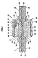
- FIGS. 1 to 3 schematically a first embodiment of a coaxial connector assembly according to the invention is shown, which is generally occupied by the reference numeral 10.
- the coaxial connector assembly 10 includes an outer sleeve 12 to which a first coaxial cable 14 is connected, and an inner sleeve 16 to which a second coaxial cable 18 is connected.
- the two coaxial cables 14, 18 are electrically and mechanically connected to each other and separated again if necessary.
- the first coaxial cable 14 comprises in the usual way an inner conductor 20 and an outer conductor 22, between which a dielectric 24 is arranged.
- the second coaxial cable 18 comprises an inner conductor 26 and an outer conductor 28, between which a dielectric 30 is arranged.
- the outer sleeve 12 has, on its rear side facing away from the inner sleeve 16, a collar-shaped first sleeve section 32, which merges via a radially outwardly directed step 34 into a second sleeve section 36 which carries a latching toothing 38 adjacent to the outer side of the step 34.
- the latching toothing 38 extends over the entire outer circumference of the second sleeve section 36.
- the outer sleeve 12 has a radially inwardly facing inner shoulder 40, to which at the level of the locking teeth 34 on the inside of the second sleeve portion 36 a circular cylindrical rear wall portion 42 connects, which merges via a conically widening central portion 44 in a circular cylindrical front wall portion 46. This is especially true FIG. 3 clear.
- the first coaxial cable 14 can be introduced with exposed outer conductor 22 until the outer conductor 22 and the dielectric 24 on the inner shoulder 40 come to rest.
- the exposed inner conductor 20 of the first coaxial cable 14 forms a contact pin which dips into the interior of the outer sleeve 12 surrounded by the second sleeve section 36.
- the inner sleeve 16 has, on its rear side facing away from the outer sleeve 12, a collar-shaped first sleeve section 48, which merges into a second sleeve section 52 via a radially outwardly directed step 50.
- an inner shoulder 54 projects radially inwardly.
- the second sleeve portion 52 surrounds a first insulating member 56 having a central through bore in which an electrically conductive inner conductor member 58 is disposed.
- the inner conductor part 58 has, facing the first coaxial cable 14, a first blind hole-like recess 60 and facing the second coaxial cable 18, the inner conductor part 58 has a blind-hole-like second recess 62.
- the second coaxial cable 18 can be introduced with exposed outer conductor 28 until the outer conductor 28 and the dielectric 30 on the inner shoulder 54 come to rest.
- the exposed inner conductor 26 of the second coaxial cable 18 forms a contact pin, which can dip into the second recess 62 of the inner conductor part to produce an electrical and mechanical connection with the inner conductor part 58th
- a receptacle for a solder preform is arranged in the region of the second recess 62, so that the inner conductor 26 of the second coaxial cable 18, after being inserted into the second recess 62, can be soldered to the inner conductor part 58 under heat.
- the second sleeve section 52 of the inner sleeve 16 has a cylindrical holding section 64, which adjoins the step 50 directly in the direction away from the first sleeve section 48.
- Adjoining the holding section 64 in the direction facing away from the first sleeve section 48 is a connecting section 66, which tapers conically in the direction of the free end 68 of the inner sleeve 16 and forms a plurality of spring tongues 70 which are elastically deformable in the radial direction.
- the free end 68 of the inner sleeve 16 takes in the inserted state a position equal to the circular cylindrical rear wall portion 42 of the outer sleeve 12 a.
- the inner sleeve 16 carries an over the outer circumference of the inner sleeve 16 extending annular bead 72 which is formed by individual annular bead portions 74, which are each arranged on a spring tongue 70.
- first insulating part 56 protrudes the first insulating part 56 in the axial direction over the free end 68 of the inner sleeve 16.
- first insulating member 56 With a front abutment surface 76, the first insulating member 56 is in the inserted state on the inner shoulder 40 of the outer sleeve 12.
- second coaxial cable 18 facing rear abutment surface 78 of the first insulating member 56 on the inner shoulder 54 of the inner sleeve 14 at.
- the protruding in the axial direction over the free end 68 of the inner sleeve 16 first insulating member 56 ensures that the inner sleeve 16 in the inserted state, the outer sleeve 12 can contact electrically only in the region of the cylindrical rear wall portion 42, but prevented an electrical contact in the axial direction is.
- a first annular space 80 extends in the region between the holding portion 64 of the inner sleeve 16 and the circular cylindrical front wall portion 46 of the outer sleeve 12, a second annular space 82 extends.
- the determination of the outer sleeve 12 on the inner sleeve 16 takes place in the in the FIGS. 1 to 3 shown coaxial connector assembly 10 by means of a second insulating member 84 which is made of the same plastic material as the first insulating member 56, preferably made of a polytetrafluoroethylene material.
- the second insulating part 84 is in the form of a clamping sleeve 86, which has a bottom 88 with a central opening 90.
- a jacket 92 adjoins the outer circumference of the bottom 88 in the axial direction, which is formed by a plurality of spring tongues 94 in its end region facing the latching toothing 38 of the outer sleeve 12.
- At the level of the holding portion 64 of the inner sleeve 16 of the jacket 92 forms in combination with the bottom 88 of a clamping member 96 which in addition to the bottom 88 facing the end portion of the shell 92 and the bottom 88 has a protruding from the bottom 88 in the axial direction collar 98 which is surrounded by the coat 92. Between the collar 98 and the jacket 92, an annular space 100 extends.
- first the first coaxial cable 14 can be soldered to the outer sleeve 12, wherein the inner conductor 20 of the first coaxial cable 14 dips into the interior of the outer sleeve 12.
- the second coaxial cable 18 can be soldered to the inner sleeve 16, wherein the inner conductor 26 of the second coaxial cable 18 dips into the second recess 62 of the inner conductor part 58 and can be soldered thereto.
- the inner sleeve 16 are inserted into the outer sleeve 12, wherein the inner conductor 26 of the first coaxial cable 14 is immersed in the first recess 60 of the inner conductor part 58.
- the inner conductor 20 of the first coaxial cable 14 can also be soldered to the inner conductor part 58.
- the clamping sleeve 86 which was previously attached to the second coaxial cable 18, are displaced in the axial direction so far that the collar 98 of the clamping member 96 in the second annulus 82 between the holding portion 64 of the inner sleeve 16 and the circular cylindrical front wall portion 46 of the outer sleeve 12 is immersed, wherein at the same time the jacket 92 surrounds the second sleeve portion 36 of the outer sleeve 12 and latched to the outer sleeve 12.
- the spring tongues 94 of the jacket 92 on its outer sleeve 12 facing inside carry snap-in projections 102 which cooperate with the locking teeth 38 to achieve a latching connection.
- the clamping sleeve 86 is pressed with its collar 98 on the holding portion 64 of the inner sleeve 16 and the jacket 92 is pressed onto the outer sleeve 12 in the region of the clamping part 96.
- the clamping sleeve 86 rests in the region of the bottom 88 on the radially outwardly directed step 50 of the inner sleeve 16 and exerts on the outer sleeve 12 an axially directed tensile force in the direction of the inner sleeve 16. This has the consequence that the first insulating member 56 is clamped with its stop surfaces 76 and 78 between the outer sleeve 12 and the inner sleeve 16.
- the outer sleeve 12 is held axially and radially immovably on the inner sleeve 16 and also a rotational movement of the outer sleeve 12 about the inner sleeve 16 is reliably prevented by means of clamping sleeve 86.
- the electrical and mechanical contacting of the inner sleeve 16 with the outer sleeve 12 takes place only in the region of the annular bead 72, which is the circular cylindrical rear wall portion 42 contacted in the radial direction.
- the circular-cylindrical rear wall section 42 forms the only contact region of the outer sleeve 12, against which the inner sleeve 16 rests in an electrically conductive manner.
- this ensures that practically no passive intermodulation is formed in the coaxial connector assembly 10.
- the coaxial connector assembly 10 is thus characterized by very good electrical transmission properties.
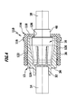
- FIG. 4 schematically a second advantageous embodiment of a coaxial connector assembly according to the invention is shown, which is generally designated by the reference numeral 110.
- the coaxial connector assembly 110 is formed substantially identical to those described above with reference to the FIGS. 1 to 3 explained coaxial connector assembly 10.
- FIG. 4 the same reference numerals as in the FIGS. 1 to 3 and with respect to these components, reference is made to the foregoing explanations to avoid repetition.
- coaxial connector assembly 110 characterized in that instead of a collar having second insulating part 84, a second insulating member 114 is used, which forms a clamping sleeve 116 without such a collar.
- the clamping sleeve 116 has a bottom 118, on the outer circumference of which a sheath 120 connects in the axial direction.
- the jacket 120 of the clamping sleeve 116 also has a plurality of spring tongues 122 which, at their free end region facing the outer sleeve 12, carry locking projections 124.
- the bottom 118 of the clamping sleeve 116 has a central opening 126 whose diameter is smaller than the diameter of the Opening 90 of the clamping sleeve 86.
- the diameter of the opening 126 is selected such that the clamping sleeve 116 can be clamped in the region of the bottom 118 with the first sleeve portion 48 of the inner sleeve 16.
- the clamping sleeve 116 unlike the clamping sleeve 86 has no collar. However, during assembly of the clamping sleeve 116 on the outer sleeve 12 of the jacket 120 is clamped to the outer sleeve 12, so that in the clamping sleeve 116 on the one hand a clamping connection with the outer sleeve 12 and on the other hand a clamping connection with the inner sleeve 16 is ensured.
- This clamp connections make it possible to fix the outer sleeve 12 also in the coaxial connector assembly 110 in the axial and radial directions immovably on the inner sleeve 16, wherein by means of the clamping sleeve 116, a rotational movement of the outer sleeve 12 is prevented relative to the inner sleeve 16.
- the coaxial connector assembly 110 is characterized by an extremely low passive intermodulation and can be produced inexpensively.
Abstract
Die Erfindung betrifft eine Koaxial-Steckverbinderanordnung mit einer Innenhülse (16) und einer Außenhülse (12), wobei die Innenhülse (16) in axialer Richtung in die Außenhülse (12) einsteckbar ist und eine Durchgangsöffnung aufweist zum Einführen eines ersten Kontaktstifts (26) und wobei die Außenhülse (12) eine zweite Durchgangsöffnung aufweist zum Einführen eines zweiten Kontaktstifts (20), und mit einem an der Innenhülse (16) festgelegten ersten Isolierteil (56), an dem ein Innenleiterteil (58) gehalten ist, wobei die beiden Kontaktstifte (20, 26) über das Innenleiterteil (58) elektrisch leitend miteinander verbindbar sind und wobei die Innenhülse (16) im eingesteckten Zustand mit ihrem der Außenhülse (12) zugewandten freien Ende (68) in axialer Richtung einen Abstand zur Außenhülse (12) einnimmt. Um die Koaxial-Steckverbinderanordnung derart weiterzubilden, dass sie eine besonders geringe passive Intermodulation aufweist, wird erfindungsgemäß vorgeschlagen, dass die Innenhülse (16) an einem einzigen Anlagebereich (42) der Außenhülse (12) elektrisch leitend anliegt, wobei der Anlagebereich (42) an einer Innenseite der Außenhülse (12) angeordnet ist und die Innenhülse (16) in Umfangsrichtung umgibt, und wobei das der Innenhülse (16) zugewandte freie Ende der Außenhülse (12) über ein zweites Isolierteil (84; 114) axial und radial unbeweglich an der Innenhülse (16) festgelegt ist.The invention relates to a coaxial connector assembly having an inner sleeve (16) and an outer sleeve (12), wherein the inner sleeve (16) in the axial direction in the outer sleeve (12) can be inserted and has a through hole for insertion of a first contact pin (26) and wherein the outer sleeve (12) has a second through-opening for insertion of a second contact pin (20), and with a first insulating part (56) fixed to the inner sleeve (16), on which an inner conductor part (58) is held, the two contact pins ( 20, 26) via the inner conductor part (58) are electrically conductively connected to each other and wherein the inner sleeve (16) in the inserted state with its outer sleeve (12) facing free end (68) in the axial direction at a distance from the outer sleeve (12) occupies. In order to further develop the coaxial connector arrangement such that it has a particularly low passive intermodulation, it is proposed according to the invention that the inner sleeve (16) is in an electrically conductive manner on a single contact region (42) of the outer sleeve (12), wherein the contact region (42) adjoins an inner side of the outer sleeve (12) and surrounds the inner sleeve (16) in the circumferential direction, and wherein the inner sleeve (16) facing free end of the outer sleeve (12) via a second insulating part (84; 114) axially and radially immovably on the Inner sleeve (16) is fixed.
Description
Die Erfindung betrifft eine Koaxial-Steckverbinderanordnung mit einer Innenhülse und einer Außenhülse, wobei die Innenhülse in axialer Richtung in die Außenhülse einsteckbar ist und eine Durchgangsöffnung aufweist zum Einführen eines ersten Kontaktstifts und wobei die Außenhülse eine zweite Durchgangsöffnung aufweist zum Einführen eines zweiten Kontaktstifts, und mit einem an der Innenhülse festgelegten ersten Isolierteil, an dem ein Innenleiterteil gehalten ist, wobei die beiden Kontaktstifte über das Innenleiterteil elektrisch leitend miteinander verbindbar sind und wobei die Innenhülse im eingesteckten Zustand mit ihrem der Außenhülse zugewandten freien Ende in axialer Richtung einen Abstand zur Außenhülse einnimmt.The invention relates to a coaxial connector assembly having an inner sleeve and an outer sleeve, wherein the inner sleeve in the axial direction in the outer sleeve can be inserted and has a through hole for insertion of a first contact pin and wherein the outer sleeve has a second through hole for insertion of a second contact pin, and with a fixed to the inner sleeve first insulating part on which an inner conductor part is held, wherein the two contact pins via the inner conductor part are electrically conductively connected to each other and wherein the inner sleeve in the inserted state with its outer sleeve facing the free end in the axial direction at a distance from the outer sleeve.
Mit Hilfe derartiger Koaxial-Steckverbinderanordnungen kann eine elektrische Verbindung hergestellt werden zwischen einem ersten Koaxialkabel und einem zweiten Koaxialkabel. In gleicher Weise kann auch eine elektrische Verbindung hergestellt werden zwischen einem Koaxialkabel und einer sonstigen elektrischen Baugruppe. Ein Endbereich des Koaxialkabels kann mit seinem Innenleiter, der einen Kontaktstift ausbildet, durch die erste Durchgangsöffnung hindurchgeführt werden, und in entsprechender Weise kann der Innenleiter eines weiteren Koaxialkabels, der ebenfalls einen Kontaktstift ausbildet, durch die zweite Durchgangsöffnung hindurchgeführt werden. Die beiden Kontaktstifte können üblicherweise in Ausnehmungen des Innenleiterteils eingeführt und über dieses elektrisch miteinander verbunden werden. Die Außenleiter der beiden Koaxialkabel können mit der Innenhülse bzw. mit der Außenhülse elektrisch verbunden werden, beispielsweise mittels einer Lötverbindung, und anschließend kann die Innenhülse in die Außenhülse eingesteckt werden, so dass über die beiden Hülsen auch die Außenleiter der Koaxialkabel elektrisch leitend miteinander verbunden sind. Die Hülsen bilden somit zwei Außenleiterteile der Koaxial-Steckverbinderanordnungen.With the aid of such coaxial connector assemblies, an electrical connection can be made between a first coaxial cable and a second coaxial cable. In the same way, an electrical connection can be made between a coaxial cable and another electrical assembly. One end portion of the coaxial cable may be passed through the first through hole with its inner conductor forming a contact pin, and, correspondingly, the inner conductor of another coaxial cable, which also forms a contact pin, may be passed through the second through hole. The two contact pins can usually be inserted into recesses of the inner conductor part and electrically connected to one another via this. The outer conductor of the two coaxial cables can be electrically connected to the inner sleeve or with the outer sleeve, for example by means of a solder joint, and then the inner sleeve can be inserted into the outer sleeve, so that via the two sleeves and the outer conductor of the coaxial cable are electrically connected to each other , The sleeves thus form two outer conductor parts of the coaxial connector assemblies.
Derartige Koaxial-Steckverbinderanordnungen sind dem Fachmann bekannt. Für das Betriebsverhalten der Koaxial-Steckverbinderanordnungen ist es von Bedeutung, dass möglichst keine passive Intermodulation (PIM) auftritt, das heißt es soll möglichst keine gegenseitige Beeinträchtigung elektrischer Signale erfolgen, die mit unterschiedlichen Frequenzen über die Koaxial-Steckverbinderanordnungen übertragen werden. Die passive Intermodulation wird unter anderem durch die Stabilität der mechanischen Verbindung der Innenhülse mit der Außenhülse beeinflusst. In der
Aufgabe der vorliegenden Erfindung ist es, eine Koaxial-Steckverbinderanordnung der eingangs genannten Art derart weiterzubilden, dass sie eine besonders geringe passive Intermodulation aufweist.Object of the present invention is to develop a coaxial connector assembly of the type mentioned in such a way that it has a particularly low passive intermodulation.
Diese Aufgabe wird bei einer Koaxial-Steckverbinderanordnung der gattungsgemäßen Art erfindungsgemäß dadurch gelöst, dass die Innenhülse an einem einzigen Anlagebereich der Außenhülse elektrisch leitend anliegt, wobei der Anlagebereich an einer Innenseite der Außenhülse angeordnet ist und die Innenhülse in Umfangsrichtung umgibt, und wobei das der Innenhülse zugewandte freie Ende der Außenhülse über ein zweites Isolierteil axial und radial unbeweglich an der Innenhülse festgelegt ist.This object is achieved in a coaxial connector assembly of the generic type according to the invention that the inner sleeve is electrically conductive on a single abutment portion of the outer sleeve, wherein the abutment portion is disposed on an inner side of the outer sleeve and surrounds the inner sleeve in the circumferential direction, and wherein the inner sleeve facing free end of the outer sleeve via a second insulating axially and radially immovably fixed to the inner sleeve.
Bei der erfindungsgemäßen Koaxial-Steckverbinderanordnung taucht die Innenhülse in die Außenhülse ein, wobei sie die Außenhülse lediglich an einem einzigen Anlagebereich kontaktiert. Dieser Anlagebereich umgibt die Innenhülse in Umfangsrichtung, so dass die Innenhülse die Außenhülse in radialer Richtung kontaktiert. Eine axiale Kontaktierung der Innenhülse mit der Außenhülse liegt nicht vor. Mit Ausnahme des die Innenhülse in Umfangsrichtung umgebenden Anlagebereichs berührt die Innenhülse die Außenhülse in keinem anderen Bereich. Um eine axiale oder radiale Bewegung der Außenhülse relativ zur Innenhülse zu vermeiden, kommt ein zweites Isolierteil zum Einsatz, über das das der Innenhülse zugewandte freie Ende der Außenhülse an der Innenhülse elektrisch isolierend festgelegt ist. Die Festlegung der Außenhülse an der Innenhülse erfolgt somit über ein elektrisch isolierendes Bauteil, das lediglich eine mechanische Arretierung der Außenhülse an der Innenhülse sicherstellt, das aber eine elektrisch leitende Verbindung der Außenhülse mit der Innenhülse im Bereich des freien Endes der Außenhülse unterbindet.In the coaxial connector assembly according to the invention, the inner sleeve dips into the outer sleeve, wherein it contacts the outer sleeve only at a single contact area. This contact area surrounds the inner sleeve in the circumferential direction, so that the inner sleeve contacts the outer sleeve in the radial direction. An axial contacting of the inner sleeve with the outer sleeve is not available. With the exception of the abutment area surrounding the inner sleeve in the circumferential direction, the inner sleeve does not touch the outer sleeve in any other area. In order to avoid an axial or radial movement of the outer sleeve relative to the inner sleeve, a second insulating part is used, via which the inner sleeve facing free end of the outer sleeve is fixed to the inner sleeve electrically insulating. The determination of the outer sleeve on the inner sleeve thus takes place via an electrically insulating component, which ensures only a mechanical locking of the outer sleeve on the inner sleeve, but which prevents an electrically conductive connection of the outer sleeve with the inner sleeve in the region of the free end of the outer sleeve.
Die erfindungsgemäße Koaxial-Steckverbinderanordnung zeichnet sich durch eine äußerst geringe passive Intermodulation aus und gleichzeitig durch eine hohe mechanische Stabilität.The coaxial connector assembly according to the invention is characterized by an extremely low passive intermodulation and at the same time by a high mechanical stability.
Der sich über den Außenumfang der Innenhülse erstreckende Anlagebereich ist günstigerweise als zylindrisch ausgestalteter Wandabschnitt der Außenhülse ausgestaltet.The contact region extending over the outer circumference of the inner sleeve is expediently configured as a cylindrical wall section of the outer sleeve.
An den zylindrischen Wandabschnitt der Außenhülse schließt sich bei einer vorteilhaften Ausführungsform der Erfindung ein sich in Richtung auf das freie Ende der Außenhülse konisch erweiternder Wandabschnitt der Außenhülse an, in den die Innenhülse eintaucht, wobei der sich konisch erweiternde Wandabschnitt und die Innenhülse zwischen sich einen Ringraum definieren.On the cylindrical wall portion of the outer sleeve joins in an advantageous embodiment of the invention in a direction towards the free end of the outer sleeve conically expanding wall portion of the outer sleeve into which the inner sleeve dips, wherein the flared wall portion and the inner sleeve between them an annulus define.
An den sich konisch erweiternden Wandabschnitt der Außenhülse kann sich in Richtung auf das freie Ende der Außenhülse ein zylindrischer Endabschnitt anschließen.At the conically widening wall portion of the outer sleeve can connect in the direction of the free end of the outer sleeve, a cylindrical end portion.
Die Außenhülse ist bei einer vorteilhaften Ausführungsform der Erfindung starr ausgebildet, so dass sie während der Montage der Koaxial-Steckverbinderan-ordnung in radialer Richtung nicht verformt werden kann.The outer sleeve is rigidly formed in an advantageous embodiment of the invention, so that it can not be deformed during assembly of the coaxial connector arrangement in the radial direction.
Wie bereits erwähnt, erfolgt die radiale und axiale Festlegung der Außenhülse an der Innenhülse mittels des zweiten Isolierteils. Günstig ist es, wenn die Außenhülse mittels des zweiten Isolierteils unverdrehbar an der Innenhülse gehalten ist. Bei einer derartigen Ausgestaltung der Erfindung kann die Außenhülse im montierten Zustand der Koaxial-Steckverbinderanordnung weder in radialer oder axialer Richtung relativ zur Innenhülse bewegt werden noch ist eine Drehbewegung der Außenhülse relativ zur Innenhülse möglich. Entsprechende Bewegungen werden durch die Bereitstellung des zweiten Isolierteils zuverlässig unterbunden.As already mentioned, the radial and axial fixing of the outer sleeve takes place on the inner sleeve by means of the second insulating part. It is favorable if the outer sleeve is held non-rotatably on the inner sleeve by means of the second insulating part. In such an embodiment of the invention, the outer sleeve can be moved in the assembled state of the coaxial connector assembly neither in the radial or axial direction relative to the inner sleeve nor is a rotational movement of the outer sleeve relative to the inner sleeve possible. Corresponding movements are reliably prevented by the provision of the second insulating part.
Das zweite Isolierteil erstreckt sich vorteilhafterweise über den Außenumfang der Innenhülse und der Außenhülse. Insbesondere kann vorgesehen sein, dass das zweite Isolierteil die Innenhülse und die Außenhülse in dem dem freien Ende der Außenhülse benachbarten Bereich vollständig umgibt.The second insulating part advantageously extends over the outer circumference of the inner sleeve and the outer sleeve. In particular, it can be provided that the second insulating part completely surrounds the inner sleeve and the outer sleeve in the region adjacent to the free end of the outer sleeve.
Die Innenhülse weist vorteilhafterweise auf ihrer der Außenhülse abgewandten Rückseite einen in axialer Richtung über das zweite Isolierteil hervorstehenden Kragen auf, der einen Endbereich eines Koaxialkabels aufnimmt.The inner sleeve advantageously has, on its rear side facing away from the outer sleeve, a collar protruding in the axial direction over the second insulating part, which collar accommodates an end region of a coaxial cable.
Bevorzugt weist die Außenhülse auf ihrer der Innenhülse abgewandten Rückseite einen in axialer Richtung über das zweite Isolierteil hervorstehenden Kragen auf, der ebenfalls einen Endbereich eines Koaxialkabels aufnimmt.Preferably, the outer sleeve on its side facing away from the inner sleeve on a rear side in the axial direction on the second insulating part protruding collar, which also receives an end portion of a coaxial cable.
Der kragenförmige Endbereich der Innenhülse und/oder der kragenförmige Endbereich der Außenhülse können einen Aufnahmeraum aufweisen, in dem ein Lotformteil positioniert werden kann zum Verlöten der Koaxialkabel mit der entsprechenden Hülse.The collar-shaped end region of the inner sleeve and / or the collar-shaped end region of the outer sleeve can have a receiving space in which a solder preform can be positioned to solder the coaxial cable to the corresponding sleeve.
Das zweite Isolierteil ist bei einer vorteilhaften Ausführungsform der Erfindung mit der Außenhülse und mit der Innenhülse verpressbar. Die Pressverbindung des zweiten Isolierteils einerseits mit der Außenhülse und andererseits mit der Innenhülse ermöglicht auf konstruktiv einfache Weise eine mechanisch belast-bare Festlegung der Außenhülse über das zweite Isolierteil an der Innenhülse.The second insulating part is compressible in an advantageous embodiment of the invention with the outer sleeve and with the inner sleeve. The press connection of the second insulating part on the one hand with the outer sleeve and on the other hand with the inner sleeve allows structurally simple manner a mechanically loadable down the outer sleeve fixing on the second insulating part on the inner sleeve.
Günstig ist es, wenn das zweite Isolierteil eine Klemmhülse ausbildet, in die die Außenhülse und die Innenhülse einpressbar sind.It is advantageous if the second insulating part forms a clamping sleeve into which the outer sleeve and the inner sleeve can be pressed.
Die Klemmhülse ist günstigerweise in axialer Richtung auf die Außenhülse und auf die Innenhülse aufpressbar. Dies ermöglicht es, die Klemmhülse vor er Montage der Koaxial-Steckverbinderanordnung auf ein Koaxialkabel aufzustecken, anschließend das Koaxialkabel über die beiden Hülsen und den Innenleiter mit einem zweiten Koaxialkabel oder einer sonstigen elektrischen Baugruppe, die einen Kontaktstift aufweist, elektrisch leitend zu verbinden, wobei die Innenhülse in die Außenhülse eingesteckt wird, und anschließend die Klemmhülse in axialer Richtung auf die Innenhülse und die Außenhülse aufzupressen, um dadurch die Außenhülse axial und radial über die Klemmhülse an der Innenhülse festzulegen.The clamping sleeve is advantageously aufpressbar in the axial direction of the outer sleeve and on the inner sleeve. This makes it possible aufzustecken the ferrule before mounting the coaxial connector assembly on a coaxial cable, then connect the coaxial cable via the two sleeves and the inner conductor with a second coaxial cable or other electrical assembly having a contact pin, electrically conductive, said Inner sleeve is inserted into the outer sleeve, and then press the clamping sleeve in the axial direction of the inner sleeve and the outer sleeve, thereby axially and radially set the outer sleeve on the inner sleeve over the clamping sleeve.
Von Vorteil ist es, wenn die zweite Isolierteil mit der Außenhülse und/oder mit der Innenhülse lösbar verbindbar ist. Dies ermöglicht es, die Verbindung zwischen der Außenhülse und der Innenhülse bei Bedarf wieder zu lösen.It is advantageous if the second insulating part with the outer sleeve and / or with the inner sleeve is releasably connectable. This makes it possible to solve the connection between the outer sleeve and the inner sleeve, if necessary.
Bei einer vorteilhaften Ausführungsform ist das zweite Isolierteil mit der Außenhülse und/oder mit der Innenhülse lösbar verrastbar.In an advantageous embodiment, the second insulating part with the outer sleeve and / or with the inner sleeve is releasably latched.
Es kann vorgesehen sein, dass das zweite Isolierteil mit der Außenhülse und/oder mit der Innenhülse verschraubbar ist.It can be provided that the second insulating part with the outer sleeve and / or with the inner sleeve can be screwed.
Günstig ist es, wenn das zweite Isolierteil mit der Außenhülse und/oder mit der Innenhülse werkzeuglos lösbar verbindbar ist. Dies erlaubt eine besonders einfache Handhabung der Koaxial-Steckverbinderanordnung.It is advantageous if the second insulating part with the outer sleeve and / or with the inner sleeve releasably connected without tools. This allows a particularly simple handling of the coaxial connector assembly.
Wie bereits erwähnt, nimmt die Innenhülse im eingesteckten Zustand mit ihrem der Außenhülse zugewandten freien Ende in axialer Richtung einen Abstand zur Außenhülse ein. Um eine unbeabsichtigte axiale Kontaktierung der Innenhülse mit der Außenhülse zuverlässig zu vermeiden, ist es von Vorteil, wenn das erste Isolierteil im eingesteckten Zustand der Innenhülse mit einer in axialer Richtung über das freie Ende der Innenhülse hervorstehenden vorderen Anschlagfläche an der Außenhülse anliegt. Dies stellt sicher, dass beim Einführen der Innenhülse in die Außenhülse das an der Innenhülse festgelegte und in axialer Richtung über das freie Ende der Innenhülse hervorstehende erste Isolierteil an der Außenhülse anschlägt, beispielsweise an einer Bodenwand der Außenhülse, noch bevor das freie Ende der Innenhülse die Außenhülse in axialer Richtung kontaktieren kann.As already mentioned, the inner sleeve in the inserted state with its outer sleeve facing the free end in the axial direction at a distance from the outer sleeve. In order to reliably prevent unintentional axial contacting of the inner sleeve with the outer sleeve, it is advantageous if the first insulating part rests in the inserted state of the inner sleeve with a protruding in the axial direction over the free end of the inner sleeve front stop surface on the outer sleeve. This ensures that when inserting the inner sleeve in the outer sleeve fixed to the inner sleeve and protruding in the axial direction over the free end of the inner sleeve first insulating member abuts the outer sleeve, for example on a bottom wall of the outer sleeve, before the free end of the inner sleeve Outer sleeve can contact in the axial direction.
Von besonderem Vorteil ist es, wenn die Außenhülse mittels des zweiten Isolierteils mit einer axialen Zugkraft in Richtung auf das erste Isolierteil beaufschlagbar ist. Bei einer derartigen Ausgestaltung zieht somit das zweite Isolierteil die Außenhülse gegen die vordere Anschlagfläche des ersten Isolierteils.It is particularly advantageous if the outer sleeve can be acted upon by means of the second insulating part with an axial tensile force in the direction of the first insulating part. In such an embodiment, the second insulating part thus pulls the outer sleeve against the front abutment surface of the first insulating part.
Das erste Isolierteil kann mit einer der Außenhülse abgewandten hinteren Anschlagfläche an der Innenhülse anliegen, vorzugsweise an einer Bodenwand der Innenhülse. Bei einer derartigen Ausgestaltung wird das erste Isolierteil unter der Wirkung einer axialen Zugkraft des zweiten Isolierteils zwischen die Innenhülse und die Außenhülse eingespannt. Dies erhöht die mechanische Belastbarkeit der Koaxial-Steckverbinderanordnung.The first insulating part may rest against the inner sleeve with a rear abutment surface facing away from the outer sleeve, preferably on a bottom wall of the inner sleeve. In such an embodiment, the first insulating part is clamped under the action of an axial tensile force of the second insulating part between the inner sleeve and the outer sleeve. This increases the mechanical strength of the coaxial connector assembly.
Das zweite Isolierteil ist günstigerweise an eine radial ausgerichtete Stufe der Außenhülse und/oder der Innenhülse anlegbar. Beispielsweise kann vorgesehen sein, dass die Innenhülse eine radial nach außen weisende Stufe aufweist, an die das zweite Isolierteil anlegbar ist. Die radial nach außen weisende Stufe bildet somit eine Anschlagfläche für das zweite Isolierteil aus.The second insulating part can be conveniently applied to a radially oriented step of the outer sleeve and / or the inner sleeve. For example, it can be provided that the inner sleeve has a radially outwardly pointing step, to which the second insulating part can be applied. The radially outwardly facing step thus forms a stop surface for the second insulating part.
Von besonderem Vorteil ist es, wenn das zweite Isolierteil ein Abstandselement aufweist, das zwischen das freie Ende der Außenhülse und die Innenhülse einsetzbar ist. Das Abstandselement nimmt somit eine Position ein zwischen dem freien Ende der Außenhülse und der Innenhülse und stellt dadurch sicher, dass die Außenhülse die Innenhülse in diesem Bereich nicht unbeabsichtigt unmittelbar kontaktieren kann.It is particularly advantageous if the second insulating part has a spacing element which can be inserted between the free end of the outer sleeve and the inner sleeve. The spacer thus occupies a position between the free end of the outer sleeve and the inner sleeve and thereby ensures that the outer sleeve can not accidentally contact the inner sleeve in this area unintentionally.
Das Abstandselement ist günstigerweise als ringförmiger Kragen ausgebildet, der unter Ausbildung eines Ringraums von einem Mantel des zweiten Isolierteils umgeben ist, wobei ein freier Endabschnitt der Außenhülse in axialer Richtung in den Ringraum und ein Abschnitt der Innenhülse in den Kragen einpressbar ist. Der Kragen kann unter elastischer und/oder plastischer Verformung an die Innenhülse angelegt werden und gleichzeitig kann der Mantel unter elastischer und/oder plastischer Verformung an die Außenhülse angelegt werden, die mit einem freien Endabschnitt in den Ringraum zwischen dem Mantel und dem Kragen eintaucht. Dies hat eine besonders hohe mechanische Belastbarkeit der Koaxial-Steckverbinderanordnung zur Folge, wobei die Außenhülse auf konstruktiv einfache Weise an der Innenhülse festgelegt werden kann und gleichzeitig sichergestellt ist, dass die Außenhülse die Innenhülse lediglich in einem sich über den Außenumfang der Innenhülse erstreckenden Anlagebereich elektrisch kontaktiert.The spacer element is conveniently formed as an annular collar which is surrounded by a jacket of the second insulating member to form an annular space, wherein a free end portion of the outer sleeve in the axial direction in the annulus and a portion of the inner sleeve is pressed into the collar. The collar can be applied to the inner sleeve with elastic and / or plastic deformation and at the same time the sheath can be applied with elastic and / or plastic deformation to the outer sleeve, which dips with a free end portion in the annular space between the sheath and the collar. This has a particularly high mechanical strength of the coaxial connector assembly result, the outer sleeve can be set in a structurally simple manner on the inner sleeve and at the same time it is ensured that the outer sleeve electrically contacts the inner sleeve only in an over the outer circumference of the inner sleeve extending contact area ,
Bevorzugt weist das zweite Isolierteil einen starren Klemmabschnitt auf, der die Außenhülse und die Innenhülse in Umfangsrichtung umgibt und an den sich in axialer Richtung ein elastisch verformbarer Verbindungsabschnitt zur Herstellung einer lösbaren Verbindung mit der Außenhülse anschließt. Der starre Klemmabschnitt stellt sicher, dass die Außenhülse axial und radial unbeweglich an der Innenhülse festgelegt werden kann, und der sich in axialer Richtung an den Klemmabschnitt anschließende Verbindungsabschnitt ermöglicht auf konstruktiv einfache Weise eine lösbare Verbindung des zweiten Isolierteils mit der Außenhülse.The second insulating part preferably has a rigid clamping section which surrounds the outer sleeve and the inner sleeve in the circumferential direction and adjoins, in the axial direction, an elastically deformable connecting section for producing a detachable connection with the outer sleeve. The rigid clamping portion ensures that the outer sleeve can be fixed axially and radially immovably to the inner sleeve, and which allows in the axial direction of the clamping portion connecting portion in a structurally simple manner, a detachable connection of the second insulating part with the outer sleeve.
Der Verbindungsabschnitt weist günstigerweise mehrere in radialer Richtung elastisch verformbare Federzungen auf.The connecting portion advantageously has a plurality of elastically deformable spring tongues in the radial direction.
Derartige Federzungen sind insbesondere bei Bereitstellung einer Rastverbindung zwischen dem zweiten Isolierteil und der Außenhülse von Vorteil. Hierzu kann vorgesehen sein, dass die Federzungen an ihrem freien Ende jeweils ein erstes Rastelement tragen, das mit einem komplementär ausgestalten Rastelement der Außenhülse zusammenwirkt.Such spring tongues are particularly advantageous when providing a latching connection between the second insulating part and the outer sleeve. For this purpose, it may be provided that the spring tongues carry at their free end in each case a first latching element, which cooperates with a complementary designed latching element of the outer sleeve.
Günstigerweise trägt die Außenhülse in ihrem der Innenhülse abgewandten Endbereich außenseitig eine Rastverzahnung, die mit komplementär ausgestalteten Rastzähnen des zweiten Isolierteils zusammenwirkt.Conveniently, the outer sleeve carries in its side facing away from the inner sleeve end portion outside a locking toothing, which cooperates with complementary designed locking teeth of the second insulating part.
Das erste Isolierteil und das zweite Isolierteil sind vorzugsweise aus demselben Kunststoffmaterial gefertigt, beispielsweise aus einem Polytetrafluorethylen-Material.The first insulating part and the second insulating part are preferably made of the same plastic material, for example of a polytetrafluoroethylene material.
Die nachfolgende Beschreibung zweier bevorzugter Ausführungsformen der Erfindung dient im Zusammenhang mit der Zeichnung der näheren Erläuterung. Es zeigen:
- Figur 1:
- eine schematische Schnittansicht einer ersten Ausführungsform einer erfindungsgemäßen Koaxial-Steckverbinderanordnung zur Herstellung einer elektrischen und mechanischen Verbindung zwischen zwei Koaxialkabeln;
- Figur 2:
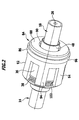
- eine perspektivische Darstellung der Koaxial-Steckverbinderanordnung aus
Figur 1 ; - Figur 3:
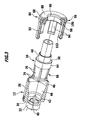
- eine perspektivische, teilweise aufgetrennte Darstellung nach Art einer Explosionszeichnung der Koaxial-Steckverbinderanordnung aus
Figur 1 , und - Figur 4:
- eine schematische Schnittansicht einer zweiten Ausführungsform einer erfindungsgemäßen Koaxial-Steckverbinderanordnung zur Herstellung einer elektrischen und mechanischen Verbindung zwischen zwei Koaxialkabeln.
- FIG. 1:
- a schematic sectional view of a first embodiment of a coaxial connector assembly according to the invention for making an electrical and mechanical connection between two coaxial cables;
- FIG. 2:
- a perspective view of the coaxial connector assembly
FIG. 1 ; - FIG. 3:
- a perspective, partially separated representation in the manner of an exploded view of the coaxial connector assembly
FIG. 1 , and - FIG. 4:
- a schematic sectional view of a second embodiment of a coaxial connector assembly according to the invention for producing an electrical and mechanical connection between two coaxial cables.
In den
Das erste Koaxialkabel 14 umfasst in üblicher Weise einen Innenleiter 20 und einen Außenleiter 22, zwischen denen ein Dielektrikum 24 angeordnet ist. Das zweite Koaxialkabel 18 umfasst einen Innenleiter 26 und einen Außenleiter 28, zwischen denen ein Dielektrikum 30 angeordnet ist.The first
Die Außenhülse 12 weist auf ihrer der Innenhülse 16 abgewandten Rückseite einen kragenförmigen ersten Hülsenabschnitt 32 auf, der über eine radial nach außen gerichtete Stufe 34 in einen zweiten Hülsenabschnitt 36 übergeht, der auf seiner Außenseite der Stufe 34 benachbart eine Rastverzahnung 38 trägt. Die Rastverzahnung 38 erstreckt sich über den kompletten Außenumfang des zweiten Hülsenabschnitts 36.The
Axial in Richtung auf die Innenhülse 16 versetzt zur Stufe 34 weist die Außenhülse 12 eine radial nach innen weisende Innenschulter 40 auf, an die sich in Höhe der Rastverzahnung 34 an der Innenseite des zweiten Hülsenabschnitts 36 ein kreiszylindrischer hinterer Wandabschnitt 42 anschließt, der über einen sich konisch erweiternden Mittelabschnitt 44 in einen kreiszylindrischen vorderen Wandabschnitt 46 übergeht. Dies wird insbesondere auch
In den kragenförmigen ersten Hülsenabschnitt 32 kann das erste Koaxialkabel 14 mit freigelegtem Außenleiter 22 so weit eingeführt werden, bis der Außenleiter 22 und das Dielektrikum 24 an der Innenschulter 40 zur Anlage gelangen. Der freigelegte Innenleiter 20 des ersten Koaxialkabels 14 bildet einen Kontaktstift aus, der in den vom zweiten Hülsenabschnitt 36 umgebenen Innenraum der Außenhülse 12 eintaucht.In the collar-shaped
Die Innenhülse 16 weist auf ihrer der Außenhülse 12 abgewandten Rückseite einen kragenförmigen ersten Hülsenabschnitt 48 auf, der über eine radial nach außen gerichtete Stufe 50 in einen zweiten Hülsenabschnitt 52 übergeht. Im Übergangsbereich zwischen dem ersten Hülsenabschnitt 48 und dem zweiten Hülsenabschnitt 52 ragt eine Innenschulter 54 radial nach innen.The
Der zweite Hülsenabschnitt 52 umgibt ein erstes Isolierteil 56, das eine zentrale Durchgangsbohrung aufweist, in der ein elektrisch leitendes Innenleiterteil 58 angeordnet ist. Das Innenleiterteil 58 weist dem ersten Koaxialkabel 14 zugewandt eine erste sacklochartige Ausnehmung 60 auf und dem zweiten Koaxialkabel 18 zugewandt weist das Innenleiterteil 58 eine sacklochartige zweite Ausnehmung 62 auf.The
In den ersten Hülsenabschnitt 48 der Innenhülse 16 kann das zweite Koaxialkabel 18 mit freigelegtem Außenleiter 28 so weit eingeführt werden, bis der Außenleiter 28 und das Dielektrikum 30 an der Innenschulter 54 zur Anlage gelangen. Der freigelegte Innenleiter 26 des zweiten Koaxialkabels 18 bildet einen Kontaktstift aus, der in die zweite Ausnehmung 62 des Innenleiterteils eintauchen kann unter Herstellung einer elektrischen und mechanischen Verbindung mit dem Innenleiterteil 58.In the
Es kann vorgesehen sein, dass im Bereich der zweiten Ausnehmung 62 eine Aufnahme für ein Lotformteil angeordnet ist, so dass der Innenleiter 26 des zweiten Koaxialkabels 18, nachdem er in die zweite Ausnehmung 62 eingeführt wurde, unter Wärmebeaufschlagung mit den Innenleiterteil 58 verlötet werden kann.It can be provided that a receptacle for a solder preform is arranged in the region of the
Der zweite Hülsenabschnitt 52 der Innenhülse 16 weist einen zylindrischen Halteabschnitt 64 auf, der sich in der dem ersten Hülsenabschnitt 48 abgewandten Richtung unmittelbar an die Stufe 50 anschließt. An den Halteabschnitt 64 schließt sich in der dem ersten Hülsenabschnitt 48 abgewandten Richtung ein Verbindungsabschnitt 66 an, der sich in Richtung auf das freie Ende 68 der Innenhülse 16 konisch verjüngt und der mehrere in radialer Richtung elastisch verformbare Federzungen 70 ausbildet.The
Das freie Ende 68 der Innenhülse 16 nimmt im eingesteckten Zustand eine Position in Höhe des kreiszylindrischen hinteren Wandabschnitts 42 der Außenhülse 12 ein. In diesem Bereich trägt die Innenhülse 16 einen sich über den Außenumfang der Innenhülse 16 erstreckenden Ringwulst 72, der von einzelnen Ringwulstabschnitten 74 gebildet wird, die jeweils an einer Federzunge 70 angeordnet sind.The
Wie insbesondere aus
Das in axialer Richtung über das freie Ende 68 der Innenhülse 16 hervorstehende erste Isolierteil 56 stellt sicher, dass die Innenhülse 16 im eingesteckten Zustand die Außenhülse 12 lediglich im Bereich des zylindrischen hinteren Wandabschnitts 42 elektrisch kontaktieren kann, das aber eine elektrische Kontaktierung in axialer Richtung unterbunden ist.The protruding in the axial direction over the
Im eingesteckten Zustand erstreckt sich zwischen dem Verbindungsabschnitt 66 der Innenhülse 16 und dem Mittelabschnitt 44 der Außenhülse 12 ein erster Ringraum 80, und im Bereich zwischen dem Halteabschnitt 64 der Innenhülse 16 und dem kreiszylindrischen vorderen Wandabschnitt 46 der Außenhülse 12 erstreckt sich ein zweiter Ringraum 82.In the inserted state extends between the connecting
Die Festlegung der Außenhülse 12 an der Innenhülse 16 erfolgt bei der in den
Das zweite Isolierteil 84 ist in Form einer Klemmhülse 86 ausgebildet, die einen Boden 88 mit einer mittigen Durchbrechung 90 aufweist. An den Außenumfang des Bodens 88 schließt sich in axialer Richtung ein Mantel 92 an, der in seinem der Rastverzahnung 38 der Außenhülse 12 zugewandten Endbereich von einer Vielzahl von Federzungen 94 gebildet wird. In Höhe des Halteabschnitts 64 der Innenhülse 16 bildet der Mantel 92 in Kombination mit dem Boden 88 ein Klemmteil 96 aus, das zusätzlich zu dem dem Boden 88 zugewandten Endabschnitt des Mantels 92 und dem Boden 88 einen vom Boden 88 in axialer Richtung abstehenden Kragen 98 aufweist, der vom Mantel 92 umgeben ist. Zwischen dem Kragen 98 und dem Mantel 92 erstreckt sich ein Ringraum 100.The second insulating
Zur Herstellung einer mechanischen und elektrischen Verbindung des ersten Koaxialkabels 14 mit dem zweiten Koaxialkabel 18 kann zunächst das erste Koaxialkabel 14 mit der Außenhülse 12 verlötet werden, wobei der Innenleiter 20 des ersten Koaxialkabels 14 in den Innenraum der Außenhülse 12 eintaucht. In entsprechender Weise kann das zweite Koaxialkabel 18 mit der Innenhülse 16 verlötet werden, wobei der Innenleiter 26 des zweiten Koaxialkabels 18 in die zweite Ausnehmung 62 des Innenleiterteils 58 eintaucht und mit diesem verlötet werden kann. Anschließend kann dann die Innenhülse 16 in die Außenhülse 12 eingesteckt werden, wobei der Innenleiter 26 des ersten Koaxialkabels 14 in die erste Ausnehmung 60 des Innenleiterteils 58 eintaucht. Mittels eines entsprechenden Lotdepots kann auch der Innenleiter 20 des ersten Koaxialkabels 14 mit dem Innenleiterteil 58 verlötet werden.To produce a mechanical and electrical connection of the first
Um anschließend die Außenhülse 12 an der Innenhülse 16 axial und radial unverschieblich festzulegen, kann in einem weiteren Montageschritt die Klemmhülse 86, die zuvor auf das zweite Koaxialkabel 18 aufgesteckt wurde, in axialer Richtung so weit verschoben werden, dass der Kragen 98 des Klemmteils 96 in den zweiten Ringraum 82 zwischen dem Halteabschnitt 64 der Innenhülse 16 und dem kreiszylindrischen vorderen Wandabschnitt 46 der Außenhülse 12 eintaucht, wobei gleichzeitig der Mantel 92 den zweiten Hülsenabschnitt 36 der Außenhülse 12 umgibt und mit der Außenhülse 12 verrastet. Hierzu tragen die Federzungen 94 des Mantels 92 auf ihrer der Außenhülse 12 zugewandten Innenseite Rastvorsprünge 102, die mit der Rastverzahnung 38 zur Erzielung einer Rastverbindung zusammenwirken.In order subsequently to fix the
Die Klemmhülse 86 wird mit ihrem Kragen 98 auf den Halteabschnitt 64 der Innenhülse 16 aufgepresst und der Mantel 92 wird im Bereich des Klemmteils 96 auf die Außenhülse 12 aufgepresst. Die Klemmhülse 86 liegt hierbei im Bereich des Bodens 88 an der radial nach außen gerichteten Stufe 50 der Innenhülse 16 an und übt auf die Außenhülse 12 eine axial gerichtete Zugkraft in Richtung auf die Innenhülse 16 aus. Dies hat zur Folge, dass das erste Isolierteil 56 mit seinen Anschlagflächen 76 und 78 zwischen die Außenhülse 12 und die Innenhülse 16 eingespannt wird.The clamping
Durch die Bereitstellung der Klemmhülse 86 ist die Außenhülse 12 axial und radial unverschieblich an der Innenhülse 16 gehalten und auch eine Drehbewegung der Außenhülse 12 um die Innenhülse 16 wird mittels er Klemmhülse 86 zuverlässig unterbunden.By providing the clamping
Die elektrische und mechanische Kontaktierung der Innenhülse 16 mit der Außenhülse 12 erfolgt lediglich im Bereich des Ringwulstes 72, der den kreiszylindrischen hinteren Wandabschnitt 42 in radialer Richtung kontaktiert. Der kreiszylindrische hintere Wandabschnitt 42 bildet den einzigen Anlagebereich der Außenhülse 12 aus, an dem die Innenhülse 16 elektrisch leitend anliegt. In Kombination mit der axialen und radialen und unverdrehbaren Festlegung der Außenhülse 12 an der Innenhülse 6 stellt dies sicher, dass sich bei der Koaxial-Steckverbinderanordnung 10 praktisch keinerlei passive Intermodulation ausbildet. Die Koaxial-Steckverbinderanordnung 10 zeichnet sich somit durch sehr gute elektrische Übertragungseigenschaften aus.The electrical and mechanical contacting of the
In
Von der Koaxial-Steckverbinderanordnung 10 unterscheidet sich die in
Ein weiterer Unterschied zwischen dem voranstehend erläuterten zweiten Isolierteil 84 und dem in
Die Klemmhülse 116 weist im Unterschied zur Klemmhülse 86 keinen Kragen auf. Allerdings wird bei der Montage der Klemmhülse 116 an der Außenhülse 12 der Mantel 120 mit der Außenhülse 12 verklemmt, so dass bei der Klemmhülse 116 einerseits eine Klemmverbindung mit der Außenhülse 12 und andererseits eine Klemmverbindung mit der Innenhülse 16 sichergestellt ist. Diese Klemmverbindungen ermöglichen es, die Außenhülse 12 auch bei der Koaxial-Steckverbinderanordnung 110 in axialer und radialer Richtung unverschieblich an der Innenhülse 16 festzulegen, wobei mittels der Klemmhülse 116 auch eine Drehbewegung der Außenhülse 12 relativ zur Innenhülse 16 unterbunden wird.The clamping
Auch die Koaxial-Steckverbinderanordnung 110 zeichnet sich durch eine äußerst geringe passive Intermodulation aus und kann kostengünstig hergestellt werden.The
Claims (15)
Applications Claiming Priority (1)
| Application Number | Priority Date | Filing Date | Title |
|---|---|---|---|
| DE102013107820.6A DE102013107820B3 (en) | 2013-07-22 | 2013-07-22 | Coaxial connector arrangement |
Publications (1)
| Publication Number | Publication Date |
|---|---|
| EP2830165A1 true EP2830165A1 (en) | 2015-01-28 |
Family
ID=51176237
Family Applications (1)
| Application Number | Title | Priority Date | Filing Date |
|---|---|---|---|
| EP14176947.1A Withdrawn EP2830165A1 (en) | 2013-07-22 | 2014-07-14 | Coaxial connector assembly |
Country Status (4)
| Country | Link |
|---|---|
| US (1) | US20150024628A1 (en) |
| EP (1) | EP2830165A1 (en) |
| CN (1) | CN104332784A (en) |
| DE (1) | DE102013107820B3 (en) |
Cited By (1)
| Publication number | Priority date | Publication date | Assignee | Title |
|---|---|---|---|---|
| EP3103163B1 (en) * | 2014-02-03 | 2021-04-07 | Telefonaktiebolaget Lm Ericsson (Publ) | Coaxial connector assembly |
Families Citing this family (17)
| Publication number | Priority date | Publication date | Assignee | Title |
|---|---|---|---|---|
| DE102013111905B9 (en) * | 2013-10-29 | 2015-10-29 | Telegärtner Karl Gärtner GmbH | Connecting device for electrically connecting two printed circuit boards |
| WO2015120576A1 (en) * | 2014-02-11 | 2015-08-20 | Commscope Technologies Llc | Coaxial cable and connector with dielectric spacer that inhibits unwanted solder flow |
| JP6587412B2 (en) * | 2015-04-16 | 2019-10-09 | 東京特殊電線株式会社 | Connection structure between high-frequency coaxial cable and coaxial connector |
| DE102015106058B4 (en) * | 2015-04-21 | 2018-06-14 | Telegärtner Karl Gärtner GmbH | connector system |
| CN107735910B (en) | 2015-05-01 | 2021-07-06 | 康普技术有限责任公司 | Coaxial cable connector interface for preventing mating with incorrect connector |
| US10272334B2 (en) * | 2016-03-16 | 2019-04-30 | Kabushiki Kaisha Square Enix | Program and system |
| DE102016113655A1 (en) * | 2016-07-25 | 2018-01-25 | Pflitsch Gmbh & Co. Kg | Device for the sealed passage of a long molded part |
| CN108011264B (en) | 2016-10-31 | 2021-08-13 | 康普技术有限责任公司 | Quick-lock coaxial connector and connector combination |
| CN106443088B (en) * | 2016-11-16 | 2023-10-03 | 国家电网公司 | Electric shock preventing connector for discharge test of small-capacity storage battery pack |
| CN106711710A (en) * | 2017-01-10 | 2017-05-24 | 贝思特宽带通讯(烟台)有限公司 | Coaxial connector and cable component comprising same |
| CN109256645B (en) | 2017-07-12 | 2021-09-21 | 康普技术有限责任公司 | Quick-locking coaxial connector |
| DE102017117679B4 (en) * | 2017-08-03 | 2019-06-13 | Ims Connector Systems Gmbh | Electrical connector |
| CN109962367B (en) * | 2019-04-25 | 2024-04-09 | 苏州祥龙嘉业电子科技股份有限公司 | Floating female seat with self-return function and coaxial connector comprising floating female seat |
| EP3780291A1 (en) * | 2019-08-12 | 2021-02-17 | Spinner GmbH | Low passive intermodulation connector system |
| EP3826118A1 (en) * | 2019-11-19 | 2021-05-26 | TE Connectivity Industrial GmbH | Coupling half for an electric plug comprising a multi-part, rotatable sleeve, as well as electric plug and method |
| DE102019131791B8 (en) * | 2019-11-25 | 2022-12-15 | Hanon Systems | Arrangements for connecting electrical connections for a device for driving a compressor and methods for assembling the arrangements and device for driving a compressor and use of the device |
| JP7292190B2 (en) * | 2019-11-29 | 2023-06-16 | ホシデン株式会社 | Ground terminal and connector with same |
Citations (6)
| Publication number | Priority date | Publication date | Assignee | Title |
|---|---|---|---|---|
| US6024609A (en) * | 1997-11-03 | 2000-02-15 | Andrew Corporation | Outer contact spring |
| US20100304579A1 (en) * | 2009-05-26 | 2010-12-02 | Brian Lyle Kisling | Low Resistance Connector For Printed Circuit Board |
| EP2385585A1 (en) * | 2010-04-16 | 2011-11-09 | Astrium Limited | Connector |
| US20120108098A1 (en) * | 2010-10-27 | 2012-05-03 | Donald Andrew Burris | Push-on cable connector with a coupler and retention and release mechanism |
| DE102011056466A1 (en) | 2011-12-15 | 2013-06-20 | Telegärtner Karl Gärtner GmbH | Coaxial connector arrangement |
| EP2615699A1 (en) * | 2012-01-11 | 2013-07-17 | Spinner GmbH | RF Connector |
Family Cites Families (4)
| Publication number | Priority date | Publication date | Assignee | Title |
|---|---|---|---|---|
| US3533051A (en) * | 1967-12-11 | 1970-10-06 | Amp Inc | Coaxial stake for high frequency cable termination |
| DE20119980U1 (en) * | 2001-12-10 | 2002-02-14 | Rosenberger Hochfrequenztech | coaxial |
| US6863565B1 (en) * | 2004-07-13 | 2005-03-08 | Palco Connector Incorporated | Constant impedance bullet connector for a semi-rigid coaxial cable |
| DE102011103524B4 (en) * | 2011-06-07 | 2013-10-02 | Rosenberger Hochfrequenztechnik Gmbh & Co. Kg | coaxial |
-
2013
- 2013-07-22 DE DE102013107820.6A patent/DE102013107820B3/en active Active
-
2014
- 2014-07-14 US US14/330,067 patent/US20150024628A1/en not_active Abandoned
- 2014-07-14 EP EP14176947.1A patent/EP2830165A1/en not_active Withdrawn
- 2014-07-22 CN CN201410350683.3A patent/CN104332784A/en active Pending
Patent Citations (7)
| Publication number | Priority date | Publication date | Assignee | Title |
|---|---|---|---|---|
| US6024609A (en) * | 1997-11-03 | 2000-02-15 | Andrew Corporation | Outer contact spring |
| US20100304579A1 (en) * | 2009-05-26 | 2010-12-02 | Brian Lyle Kisling | Low Resistance Connector For Printed Circuit Board |
| EP2385585A1 (en) * | 2010-04-16 | 2011-11-09 | Astrium Limited | Connector |
| US20120108098A1 (en) * | 2010-10-27 | 2012-05-03 | Donald Andrew Burris | Push-on cable connector with a coupler and retention and release mechanism |
| WO2012058039A1 (en) * | 2010-10-27 | 2012-05-03 | Corning Gilbert Inc. | Push-on cable connector with a coupler and retention and release mechanism |
| DE102011056466A1 (en) | 2011-12-15 | 2013-06-20 | Telegärtner Karl Gärtner GmbH | Coaxial connector arrangement |
| EP2615699A1 (en) * | 2012-01-11 | 2013-07-17 | Spinner GmbH | RF Connector |
Cited By (1)
| Publication number | Priority date | Publication date | Assignee | Title |
|---|---|---|---|---|
| EP3103163B1 (en) * | 2014-02-03 | 2021-04-07 | Telefonaktiebolaget Lm Ericsson (Publ) | Coaxial connector assembly |
Also Published As
| Publication number | Publication date |
|---|---|
| US20150024628A1 (en) | 2015-01-22 |
| CN104332784A (en) | 2015-02-04 |
| DE102013107820B3 (en) | 2014-11-06 |
Similar Documents
| Publication | Publication Date | Title |
|---|---|---|
| DE102013107820B3 (en) | Coaxial connector arrangement | |
| EP3103163B1 (en) | Coaxial connector assembly | |
| EP3198686B1 (en) | Plug-in connector | |
| EP2605338B1 (en) | Coaxial connector assembly | |
| DE69912912T2 (en) | Connector lock and electrical connector with such a connector lock | |
| EP3420612B1 (en) | Electrical plug connector | |
| EP3396793B1 (en) | Contact body for a connector | |
| EP3262722B1 (en) | Plug connection comprising a locking device | |
| DE102009016227B4 (en) | Connector with a connected coaxial cable | |
| EP0772261A2 (en) | Coaxial connector | |
| DE102016006598A1 (en) | Connectors | |
| EP3443620A1 (en) | Plug connector | |
| DE102017112025B4 (en) | Electrical connector with tolerance compensation | |
| EP3579346B1 (en) | Electrical connector for circuit boards | |
| DE102014109040A1 (en) | Cable component | |
| DE10140153B4 (en) | Plug connection for the simultaneous connection of several coaxial cables | |
| EP3203591B1 (en) | Connector | |
| DE102004041809B4 (en) | angle coupler | |
| EP1467441A2 (en) | Connector for quick connection in collet attachment technologie | |
| DE102014116482B4 (en) | Contact element | |
| WO2019101262A1 (en) | Plug-type connector | |
| EP3605746B1 (en) | Plug connector and connection with such a connector | |
| DE102017222809A1 (en) | Electrical connector and connector | |
| DE10237666B4 (en) | connector element | |
| DE10045263B4 (en) | connectors |
Legal Events
| Date | Code | Title | Description |
|---|---|---|---|
| 17P | Request for examination filed |
Effective date: 20140714 |
|
| AK | Designated contracting states |
Kind code of ref document: A1 Designated state(s): AL AT BE BG CH CY CZ DE DK EE ES FI FR GB GR HR HU IE IS IT LI LT LU LV MC MK MT NL NO PL PT RO RS SE SI SK SM TR |
|
| AX | Request for extension of the european patent |
Extension state: BA ME |
|
| PUAI | Public reference made under article 153(3) epc to a published international application that has entered the european phase |
Free format text: ORIGINAL CODE: 0009012 |
|
| STAA | Information on the status of an ep patent application or granted ep patent |
Free format text: STATUS: THE APPLICATION IS DEEMED TO BE WITHDRAWN |
|
| 18D | Application deemed to be withdrawn |
Effective date: 20150729 |