EP2829942A2 - Air purging pressure regulating valve - Google Patents
Air purging pressure regulating valve Download PDFInfo
- Publication number
- EP2829942A2 EP2829942A2 EP20140177120 EP14177120A EP2829942A2 EP 2829942 A2 EP2829942 A2 EP 2829942A2 EP 20140177120 EP20140177120 EP 20140177120 EP 14177120 A EP14177120 A EP 14177120A EP 2829942 A2 EP2829942 A2 EP 2829942A2
- Authority
- EP
- European Patent Office
- Prior art keywords
- spool
- damper
- regulating valve
- pressure regulating
- set forth
- Prior art date
- Legal status (The legal status is an assumption and is not a legal conclusion. Google has not performed a legal analysis and makes no representation as to the accuracy of the status listed.)
- Granted
Links
Images


Classifications
-
- F—MECHANICAL ENGINEERING; LIGHTING; HEATING; WEAPONS; BLASTING
- F16—ENGINEERING ELEMENTS AND UNITS; GENERAL MEASURES FOR PRODUCING AND MAINTAINING EFFECTIVE FUNCTIONING OF MACHINES OR INSTALLATIONS; THERMAL INSULATION IN GENERAL
- F16K—VALVES; TAPS; COCKS; ACTUATING-FLOATS; DEVICES FOR VENTING OR AERATING
- F16K15/00—Check valves
- F16K15/02—Check valves with guided rigid valve members
- F16K15/025—Check valves with guided rigid valve members the valve being loaded by a spring
-
- F—MECHANICAL ENGINEERING; LIGHTING; HEATING; WEAPONS; BLASTING
- F16—ENGINEERING ELEMENTS AND UNITS; GENERAL MEASURES FOR PRODUCING AND MAINTAINING EFFECTIVE FUNCTIONING OF MACHINES OR INSTALLATIONS; THERMAL INSULATION IN GENERAL
- F16K—VALVES; TAPS; COCKS; ACTUATING-FLOATS; DEVICES FOR VENTING OR AERATING
- F16K47/00—Means in valves for absorbing fluid energy
- F16K47/01—Damping of valve members
-
- G—PHYSICS
- G05—CONTROLLING; REGULATING
- G05D—SYSTEMS FOR CONTROLLING OR REGULATING NON-ELECTRIC VARIABLES
- G05D16/00—Control of fluid pressure
- G05D16/04—Control of fluid pressure without auxiliary power
- G05D16/10—Control of fluid pressure without auxiliary power the sensing element being a piston or plunger
-
- Y—GENERAL TAGGING OF NEW TECHNOLOGICAL DEVELOPMENTS; GENERAL TAGGING OF CROSS-SECTIONAL TECHNOLOGIES SPANNING OVER SEVERAL SECTIONS OF THE IPC; TECHNICAL SUBJECTS COVERED BY FORMER USPC CROSS-REFERENCE ART COLLECTIONS [XRACs] AND DIGESTS
- Y10—TECHNICAL SUBJECTS COVERED BY FORMER USPC
- Y10T—TECHNICAL SUBJECTS COVERED BY FORMER US CLASSIFICATION
- Y10T137/00—Fluid handling
- Y10T137/7722—Line condition change responsive valves
- Y10T137/7837—Direct response valves [i.e., check valve type]
- Y10T137/7904—Reciprocating valves
- Y10T137/7922—Spring biased
-
- Y—GENERAL TAGGING OF NEW TECHNOLOGICAL DEVELOPMENTS; GENERAL TAGGING OF CROSS-SECTIONAL TECHNOLOGIES SPANNING OVER SEVERAL SECTIONS OF THE IPC; TECHNICAL SUBJECTS COVERED BY FORMER USPC CROSS-REFERENCE ART COLLECTIONS [XRACs] AND DIGESTS
- Y10—TECHNICAL SUBJECTS COVERED BY FORMER USPC
- Y10T—TECHNICAL SUBJECTS COVERED BY FORMER US CLASSIFICATION
- Y10T137/00—Fluid handling
- Y10T137/8593—Systems
- Y10T137/85978—With pump
- Y10T137/85986—Pumped fluid control
- Y10T137/86002—Fluid pressure responsive
- Y10T137/86019—Direct response valve
Definitions
- This application relates to a pressure regulating valve wherein entrapped air in damping chambers is purged.
- Modem aircraft include more and more complex systems.
- One component typically found on an aircraft is a generator, which is driven by a prime mover and generates electricity.
- Generator components require lubrication and cooling and, thus, a lubrication pump is typically included within a generator housing and may be driven by the generator.
- a generator speed varies with operation of the associated prime mover, and thus the speed of the oil pump will also vary. This can result in the pressure of the oil supplied by the oil pump sometimes being unduly high or low.
- the oil pump typically drives the oil through a heat exchanger and then to components to be cooled.
- a pressure regulating valve is included in the path of the oil.
- the pressure regulating valve may be provided with damper chambers which serve to control the speed of movement of the valve and also ensure stable dynamic performance.
- the damping action is typically provided by oil in the chambers moving through orifices. However, air can become entrained in this oil, which reduces the damping effect.
- a pressure regulating valve has a valve housing receiving a spool and the spool has a regulating chamber selectively communicating a main supply line to a main return line.
- the spool is biased in one direction by a spring force and there is a second force biasing the spool in an opposed direction.
- the second force is provided by a fluid pressure within a hydraulic system associated with the pressure regulating valve.
- the amount of communication between a main supply port and a main return port is regulated by a position of the spool as the bias force from the fluid pressure changes. This regulates the pressure provided downstream of the pressure regulating valve.
- Damper chambers are provided on opposed sides of the spool and serve to dampen a speed of movement of the spool.
- a damper supply line supplies fluid into the damper chambers through check valves. The damper supply line serves to assist in purging air outwardly of the damper chambers.
- a generator system 20 is illustrated in Figure 1 , and includes a prime mover 17 which drives the generator 22.
- the prime mover 17 may be an auxiliary power unit or a main gas turbine engine associated with an aircraft.
- the generator is received within a housing 15. When the generator is driven to rotate, it drives an oil pump 24 through a gear train 23.
- a discharge line 25 from the oil pump 24 passes through a pressure regulating valve 26, which may dump oil through a line 27 back to a sump 19.
- Oil passing downstream of the pressure regulating valve 26 reaches a heat exchanger 30 and a downstream line 32 passes from the heat exchanger 30 to lubricate and cool locations on the generator 22.
- the heat exchanger 30 may receive a flow of air, such as from air impingement or driven by a fan 16 to cool the oil.
- the generator system 20 is shown in an extremely schematic form in Figure 1 .
- pressure regulating valve 26 may actually be inside housing 15.
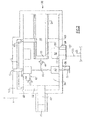
- FIG. 2 illustrates an embodiment of the pressure regulating valve 26 which may be utilized in the Figure 1 system.
- a sense piston 45 may see the pressure on the line 32. As this pressure increases, the sense piston 45 is biased to the right against a valve spool 34.
- Spool 34 includes a valve body and main regulating chamber 52. Regulating main chamber 52 is shown communicating a discharge pressure tap or supply line 125 through a main supply port 111 to a main return line 27 through a main return port 99. As shown, an outer land 50 of the spool 34 is driven to the left or right to block or open the connection between ports 111 and 99.
- a spring 54 mounted about a spring support stem 61 drives the spool 34 to the left as shown in this Figure and against the force from the sense piston 45.
- the spring 54 thus acts in opposition to a pressure increase on the line 32.
- the spool 34 is driven to positions at which it communicates more of the flow from main supply line 125 to the main return line 27.
- the spring 54 drives the spool 34 to positions wherein less of the connection to main return line 27 is open and more is blocked by the land 50 of the spool 34. In this manner, the pressure reaching the heat exchanger 30 is regulated, and unduly high or low pressures do not reach the heat exchanger 30.
- the spool 34 may move at excessively high speeds and, thus, a damper function is provided in the pressure regulating valve 26.
- the damper function is provided by opposed damper volumes or chambers 60/69 and 62.
- the chamber 62 resists movement of the spool 34 to the left.
- the opposed chamber 60 is formed about the spring stem 61 and further includes a chamber 69. The combined chamber 60 and 69 resist movement of the spool 34 to the right.
- connection line 70 connects the chambers 62 and 69 to the return line 27. Damping orifices 66 and 68 resist the flow of the oil from damping chambers 62 and 69 to the connection line 70. This thus serves to limit the speed of movement of the spool 34. As shown, the connection line 70 communicates with the return line 27.
- connection line 70 and the orifices 66 and 68 are preferably within the upper vertical half of a housing 100 for the pressure regulating valve 26. More preferably, they are within an upper 45 degrees either side of vertical and, even more preferably, the passages are mounted at a vertically uppermost or top dead center location on the housing 100. In this manner, any air entrained in the oil within the damping chambers 62 and 60/69 will tend to flow into the connection line 70 and be returned to the sump.
- damper supply line 36 Further urging the air out of the damping chamber volumes is a damper supply line 36.
- the damper supply line 36 may be taken from the discharge line 25 in one embodiment and may be filtered before passing through an orifice 38 and into a damper supply chamber 40 formed within the spool 34. Chamber 40 communicates with a tap 56, which also is returned to the line 27 leading back to the sump 19.
- Chamber 40 communicates with a damper supply passage 42 that passes through a check valve 44 into the chamber 60 and then chamber 69.
- a similar check valve 64 regulates the flow of supply oil through passage 63 into the chamber 62.
- the check valves 64/44 need not be extremely fluid tight, but rather simply need to serve as a resistance to flow from the oil leaving the chambers 62 and 60/69.
- the back-flow resistance of the check valve should be at least an order-of-magnitude greater than the flow resistance of the damper orifice 66 and 68.
- the orifice 38 has an impedance of at least one order of magnitude higher than a return-to-case impedance through a tap 56 to line 27. This ensures that the pressure in chamber 40 is at least one order of magnitude lower than a supply pressure seen on the main supply line 125, thus not significantly skewing an equilibrium position of spool 34, as balanced between pressure 32 and spring 54.
- the tap line 125 communicates with the discharge line 25, which communicates into the main regulating chamber 52.
- the entire flow on the line 25 does not pass through the main regulating chamber 52.
- Figure 3 shows another embodiment 126. Much of the embodiment 126 is similar to Figure 2 and, thus, those portions are identified by the same reference numerals.
- the sense piston 145 now includes an internal passage 140 and a transfer tube 147.
- the transfer tube 147 extends into a bore 149 in the spool 134.
- the passage 140 through the tube 147 connects into the connection passage 42, which can then supply the oil through the check valves 64 and 44 as in the Figure 2 embodiment.
- An orifice 138 is designed to have the similar impedance factor as the orifice 38.
- the supply of oil into the damper chambers 62 and 60/69 ensures that the oil found in those chambers will be relatively air free compared to the prior art and will further serve to drive the air upwardly through the damping orifices 66 and 68 and to the return line 27.
- pressure regulating valves 26 and 126 may be utilized in a generator system, such as shown in Figure 1 , they may also have application in other hydraulic systems requiring a pressure regulating valve function.
Landscapes
- Engineering & Computer Science (AREA)
- General Engineering & Computer Science (AREA)
- Physics & Mathematics (AREA)
- Mechanical Engineering (AREA)
- Fluid Mechanics (AREA)
- General Physics & Mathematics (AREA)
- Automation & Control Theory (AREA)
- Fluid-Damping Devices (AREA)
- Safety Valves (AREA)
- Multiple-Way Valves (AREA)
Abstract
Description
- This application relates to a pressure regulating valve wherein entrapped air in damping chambers is purged.
- Modem aircraft include more and more complex systems. One component typically found on an aircraft is a generator, which is driven by a prime mover and generates electricity. Generator components require lubrication and cooling and, thus, a lubrication pump is typically included within a generator housing and may be driven by the generator.
- A generator speed varies with operation of the associated prime mover, and thus the speed of the oil pump will also vary. This can result in the pressure of the oil supplied by the oil pump sometimes being unduly high or low.
- The oil pump typically drives the oil through a heat exchanger and then to components to be cooled. To ensure that unduly high or low pressures do not reach downstream locations, a pressure regulating valve is included in the path of the oil.
- The pressure regulating valve may be provided with damper chambers which serve to control the speed of movement of the valve and also ensure stable dynamic performance.
- The damping action is typically provided by oil in the chambers moving through orifices. However, air can become entrained in this oil, which reduces the damping effect.
- A pressure regulating valve has a valve housing receiving a spool and the spool has a regulating chamber selectively communicating a main supply line to a main return line. The spool is biased in one direction by a spring force and there is a second force biasing the spool in an opposed direction. The second force is provided by a fluid pressure within a hydraulic system associated with the pressure regulating valve. The amount of communication between a main supply port and a main return port is regulated by a position of the spool as the bias force from the fluid pressure changes. This regulates the pressure provided downstream of the pressure regulating valve. Damper chambers are provided on opposed sides of the spool and serve to dampen a speed of movement of the spool. A damper supply line supplies fluid into the damper chambers through check valves. The damper supply line serves to assist in purging air outwardly of the damper chambers.
- These and other features may be best understood from the following drawings and specification.
-
-
Figure 1 schematically shows a generator system. -
Figure 2 shows the first embodiment pressure regulating valve. -
Figure 3 shows a second embodiment pressure regulating valve. - A
generator system 20 is illustrated inFigure 1 , and includes aprime mover 17 which drives thegenerator 22. Theprime mover 17 may be an auxiliary power unit or a main gas turbine engine associated with an aircraft. The generator is received within ahousing 15. When the generator is driven to rotate, it drives anoil pump 24 through agear train 23. Adischarge line 25 from theoil pump 24 passes through apressure regulating valve 26, which may dump oil through aline 27 back to asump 19. - Oil passing downstream of the
pressure regulating valve 26 reaches aheat exchanger 30 and adownstream line 32 passes from theheat exchanger 30 to lubricate and cool locations on thegenerator 22. Theheat exchanger 30 may receive a flow of air, such as from air impingement or driven by afan 16 to cool the oil. It should be understood that thegenerator system 20 is shown in an extremely schematic form inFigure 1 . Also, it should be understood thatpressure regulating valve 26 may actually be insidehousing 15. -
Figure 2 illustrates an embodiment of thepressure regulating valve 26 which may be utilized in theFigure 1 system. Asense piston 45 may see the pressure on theline 32. As this pressure increases, thesense piston 45 is biased to the right against avalve spool 34. Spool 34 includes a valve body and main regulatingchamber 52. Regulatingmain chamber 52 is shown communicating a discharge pressure tap orsupply line 125 through amain supply port 111 to amain return line 27 through amain return port 99. As shown, anouter land 50 of thespool 34 is driven to the left or right to block or open the connection betweenports - A
spring 54 mounted about aspring support stem 61 drives thespool 34 to the left as shown in this Figure and against the force from thesense piston 45. - The
spring 54 thus acts in opposition to a pressure increase on theline 32. As the pressure online 32 increases, thespool 34 is driven to positions at which it communicates more of the flow frommain supply line 125 to themain return line 27. - As the pressure on
line 32 decreases, thespring 54 drives thespool 34 to positions wherein less of the connection tomain return line 27 is open and more is blocked by theland 50 of thespool 34. In this manner, the pressure reaching theheat exchanger 30 is regulated, and unduly high or low pressures do not reach theheat exchanger 30. - The
spool 34 may move at excessively high speeds and, thus, a damper function is provided in thepressure regulating valve 26. The damper function is provided by opposed damper volumes orchambers 60/69 and 62. Thechamber 62 resists movement of thespool 34 to the left. Theopposed chamber 60 is formed about thespring stem 61 and further includes achamber 69. The combinedchamber spool 34 to the right. - A
connection line 70 connects thechambers return line 27.Damping orifices damping chambers connection line 70. This thus serves to limit the speed of movement of thespool 34. As shown, theconnection line 70 communicates with thereturn line 27. - As
spool 34 is urged to the left, the volume of thechamber 62 will decrease. Oil in thechamber 62 will be driven throughorifice 66, toconnection line 70, and to returnline 27. Theorifice 66 slows the movement of this oil, and in turn slows the speed of movement of thespool 34. If thespool 34 is forced to the right as shown in this Figure, the flow is from thechamber 69, through theorifice 68, toconnection line 70, and to returnline 27. Again, this will slow the movement of thespool 34. - As shown by the arrow V, the
connection line 70 and theorifices housing 100 for thepressure regulating valve 26. More preferably, they are within an upper 45 degrees either side of vertical and, even more preferably, the passages are mounted at a vertically uppermost or top dead center location on thehousing 100. In this manner, any air entrained in the oil within thedamping chambers connection line 70 and be returned to the sump. - Further urging the air out of the damping chamber volumes is a
damper supply line 36. Thedamper supply line 36 may be taken from thedischarge line 25 in one embodiment and may be filtered before passing through anorifice 38 and into adamper supply chamber 40 formed within thespool 34.Chamber 40 communicates with atap 56, which also is returned to theline 27 leading back to thesump 19. -
Chamber 40 communicates with adamper supply passage 42 that passes through acheck valve 44 into thechamber 60 and thenchamber 69. Asimilar check valve 64 regulates the flow of supply oil throughpassage 63 into thechamber 62. Thecheck valves 64/44 need not be extremely fluid tight, but rather simply need to serve as a resistance to flow from the oil leaving thechambers damper orifice - As air becomes entrained in the damping chambers, the supply of oil through the
check valves damper orifice connection line 70, and then to returnline 27. - The
orifice 38 has an impedance of at least one order of magnitude higher than a return-to-case impedance through atap 56 toline 27. This ensures that the pressure inchamber 40 is at least one order of magnitude lower than a supply pressure seen on themain supply line 125, thus not significantly skewing an equilibrium position ofspool 34, as balanced betweenpressure 32 andspring 54. - It should be understood that while the
tap 56 is shown communicating with asingle line 27, which also receives the return from the main regulatingchamber 52, these could be two separate return lines. Moreover, these lines may simply dump back into the sump 59 should thepressure regulating valve 26 be mounted within thehousing 15. - As is also shown, the
tap line 125 communicates with thedischarge line 25, which communicates into the main regulatingchamber 52. Thus, the entire flow on theline 25 does not pass through the main regulatingchamber 52. -
Figure 3 shows anotherembodiment 126. Much of theembodiment 126 is similar toFigure 2 and, thus, those portions are identified by the same reference numerals. However, thesense piston 145 now includes aninternal passage 140 and atransfer tube 147. Thetransfer tube 147 extends into abore 149 in thespool 134. Thepassage 140 through thetube 147 connects into theconnection passage 42, which can then supply the oil through thecheck valves Figure 2 embodiment. - An
orifice 138 is designed to have the similar impedance factor as theorifice 38. - There may be clearance between an outer periphery of the transfer tube 144 and an inner periphery of the
sense piston 145 to accommodate radial misalignment ofspool 34 andsense piston 45. - The supply of oil into the
damper chambers orifices return line 27. - While the
pressure regulating valves Figure 1 , they may also have application in other hydraulic systems requiring a pressure regulating valve function. - Although an embodiment of this invention has been disclosed, a worker of ordinary skill in this art would recognize that certain modifications would come within the scope of this disclosure. For that reason, the following claims should be studied to determine the true scope and content of this disclosure.
Claims (15)
- A pressure regulating valve (26) comprising:a valve housing receiving a spool (34), said spool having a regulating chamber (52) selectively communicating a main supply port (111) to a main return port (99), and said spool being biased in one direction by a spring force and there being a second force biasing said spool in an opposed direction, with said second force being provided by a fluid pressure within a hydraulic system associated with said pressure regulating valve, communication between said main supply port and said main return port being regulated by a position of said spool as the second force changes; anddamper chambers provided on opposed sides of said spool (34), and serving to dampen a speed of movement of said spool, and a damper supply line (36) for supplying fluid into said damper chambers through check valves, said damper supply line serving to assist in purging air outwardly of said damper chambers.
- The pressure regulating valve as set forth in claim 1, wherein said damper chambers communicate to a damper return passage through damping orifices (66, 68) to allow removal of air from said damper chambers.
- The pressure regulating valve as set forth in claim 2, wherein said damper return passage is downstream of the damping orifice (66, 68) associated with each of said damper chambers, and said damping orifice (66, 68) provides a damper function by regulating a flow of the fluid between each said damper chamber and said damper return passage as the spool (34) moves under the influence of the second force and the spring force.
- The pressure regulating valve as set forth in claim 3, wherein said damping orifices (66, 68) are provided in a vertically upper location of the housing.
- The pressure regulating valve as set forth in claim 4, wherein said damping orifices (66, 68) are provided at top dead center of said housing.
- The pressure regulating valve as set forth in claim 1, wherein said damper supply line (36) passes through a feed orifice to lower a pressure of the fluid being supplied through the check valves (44, 64).
- The pressure regulating valve as set forth in claim 1, wherein said damper supply line (36) receives a discharge pressure from a pump associated with a system including said pressure regulating valve.
- The pressure regulating valve as set forth in claim 1, wherein said damper supply line (36) passes into a chamber defined in an outer periphery of said spool (34).
- The pressure regulating valve as set forth in claim 1, wherein a sense piston (45) is biased by the second force against said spool (34).
- The pressure regulating valve as set forth in claim 9, wherein said sense piston (45) includes a central bore and said central bore communicates the damper supply fluid into a chamber within said spool (34).
- A generator oil supply system comprising:a generator housing receiving a pump (24) driven by a generator (22), a pressure regulating valve (26) positioned downstream of said pump (24) and a heat exchanger (30) positioned downstream of said pressure regulating valve;the pressure regulating valve (26) including a valve housing receiving a spool, said spool having a regulating chamber (52) selectively communicating a main supply port (111) to a main return port (99), and the main supply line receiving fluid from a pump discharge line, and said spool being biased in one direction by a spring force and there being a second force biasing said spool in an opposed direction, with said second force being provided by a fluid pressure indicative of a pressure within the oil supply system, communication between a main supply port and a main return port being regulated by a position of said spool as the second force changes; anddamper chambers provided on opposed sides of said spool (34), and serving to dampen a speed of movement of said spool, and a damper supply line (36) for supplying fluid into said damper chambers through check valves, said damper supply line serving to assist in purging air outwardly of said damper chambers.
- The generator oil supply system as set forth in claim 11, wherein said damper chambers communicate to a damper return passage through damping orifices (66, 68) to allow removal of air from said damper chambers.
- The generator oil supply system as set forth in claim 12, wherein said damper return passage is downstream of one of the damping orifices (66, 68) associated with each of said damper chambers, and said damping orifices providing a damper function by regulating a flow of the fluid between each said damper chamber and return passage as the spool (34) moves under the influence of the second force and the spring force.
- The generator oil supply system as set forth in claim 13, wherein said damping orifices (66, 68) are provided in a vertically upper location of the housing.
- The generator oil supply system as set forth in claim 14, wherein said damping orifices (66, 68) are provided at top dead center of said housing.
Applications Claiming Priority (1)
| Application Number | Priority Date | Filing Date | Title |
|---|---|---|---|
| US13/950,611 US9316325B2 (en) | 2013-07-25 | 2013-07-25 | Air purging pressure regulating valve |
Publications (3)
| Publication Number | Publication Date |
|---|---|
| EP2829942A2 true EP2829942A2 (en) | 2015-01-28 |
| EP2829942A3 EP2829942A3 (en) | 2015-02-25 |
| EP2829942B1 EP2829942B1 (en) | 2019-01-02 |
Family
ID=51205255
Family Applications (1)
| Application Number | Title | Priority Date | Filing Date |
|---|---|---|---|
| EP14177120.4A Active EP2829942B1 (en) | 2013-07-25 | 2014-07-15 | Air purging pressure regulating valve |
Country Status (2)
| Country | Link |
|---|---|
| US (1) | US9316325B2 (en) |
| EP (1) | EP2829942B1 (en) |
Families Citing this family (2)
| Publication number | Priority date | Publication date | Assignee | Title |
|---|---|---|---|---|
| EP3246781B1 (en) | 2016-05-18 | 2020-06-24 | Microtecnica S.r.l. | Pressure regulation valve |
| GB2571533B (en) * | 2018-02-28 | 2022-06-08 | Safran Electrical & Power | A coolant system |
Family Cites Families (16)
| Publication number | Priority date | Publication date | Assignee | Title |
|---|---|---|---|---|
| US4161189A (en) | 1976-08-16 | 1979-07-17 | Massey-Ferguson Inc. | Control valve |
| US4168721A (en) | 1977-06-16 | 1979-09-25 | Massey-Ferguson Inc. | Pressure control valve |
| US4531709A (en) * | 1983-12-02 | 1985-07-30 | Dresser Industries, Inc. | Hydraulic control valve with fluid dampening system |
| DE4017074A1 (en) | 1990-05-26 | 1991-11-28 | Mann & Hummel Filter | PRESSURE CONTROL VALVE FOR THE CRANKCASE VENTILATION ON AN INTERNAL COMBUSTION ENGINE |
| US5163706A (en) | 1991-04-24 | 1992-11-17 | General Motors Corporation | Electro-hydraulic pressure regulating valve assembly for a hydraulic damper |
| DE4115594A1 (en) | 1991-05-14 | 1992-11-19 | Bosch Gmbh Robert | PROPORTIONAL PRESSURE CONTROL VALVE |
| JP3601554B2 (en) | 1995-08-11 | 2004-12-15 | アイシン・エィ・ダブリュ株式会社 | Solenoid pressure regulator |
| DE19962960A1 (en) | 1999-12-24 | 2001-06-28 | Bosch Gmbh Robert | Pressure control valve, in fuel feed to vehicle IC motor, has throttled outflow after valve seat to compensate unavoidable fuel line losses |
| US6289919B1 (en) | 2000-06-05 | 2001-09-18 | Hamilton Sundstrand Corporation | Pressure regulating valve with integral damping |
| JP4030491B2 (en) * | 2003-10-15 | 2008-01-09 | 株式会社ケーヒン | Normally open hydraulic control valve |
| JP3784797B2 (en) * | 2003-10-15 | 2006-06-14 | 株式会社ケーヒン | Damper device for hydraulic control valve |
| JP4258462B2 (en) | 2004-11-19 | 2009-04-30 | セイコーエプソン株式会社 | Pressure regulating valve, functional liquid supply device and drawing device |
| JP4770666B2 (en) * | 2006-09-21 | 2011-09-14 | 株式会社デンソー | Spool valve |
| US8485218B2 (en) * | 2009-05-06 | 2013-07-16 | Hamilton Sundstrand Corporation | Oil pressure regulating valve for generator applications |
| US8316880B2 (en) * | 2009-05-08 | 2012-11-27 | Hamilton Sundstrand Corporation | Oil filter bypass valve assembly for a generator |
| US8439073B2 (en) | 2010-09-10 | 2013-05-14 | Hamilton Sundstrand Corporation | Gate valve |
-
2013
- 2013-07-25 US US13/950,611 patent/US9316325B2/en active Active
-
2014
- 2014-07-15 EP EP14177120.4A patent/EP2829942B1/en active Active
Non-Patent Citations (1)
| Title |
|---|
| None |
Also Published As
| Publication number | Publication date |
|---|---|
| US20150027568A1 (en) | 2015-01-29 |
| US9316325B2 (en) | 2016-04-19 |
| EP2829942A3 (en) | 2015-02-25 |
| EP2829942B1 (en) | 2019-01-02 |
Similar Documents
| Publication | Publication Date | Title |
|---|---|---|
| US9068497B2 (en) | Oil supply system for an engine | |
| JP6147655B2 (en) | Turbocharger lubrication oil supply mechanism | |
| US10794468B2 (en) | Hydraulic system for a transmission of a motor vehicle | |
| JP2014503748A (en) | Oil pump with selectable outlet pressure | |
| US8967195B2 (en) | Pressure relief valve with orifice | |
| KR20120027038A (en) | Lubricant pump system | |
| US10662977B2 (en) | Vehicle hydraulic system | |
| US9482225B2 (en) | Gear pump, pumping apparatus including the same, and aircraft fuel system including gear pump | |
| CN105090426A (en) | Transmission hydraulic control system including thermal valve | |
| EP2829942B1 (en) | Air purging pressure regulating valve | |
| CN107061970B (en) | Motor vehicle lubricating pump system with two-piece relief valve | |
| CN106870357A (en) | Variable displacement vane pump | |
| US11022157B2 (en) | Cooling-prioritization valve for a hydraulic system of a motor vehicle transmission | |
| US20150338857A1 (en) | Pressure-regulating valves | |
| KR102836519B1 (en) | System pressure valve for hydraulic system of automobile transmission | |
| US10077834B2 (en) | Hydraulic control system for a transmission | |
| JP6258772B2 (en) | Internal combustion engine flow control valve | |
| JP6225009B2 (en) | Turbocharger lubrication oil supply mechanism | |
| JPH01275905A (en) | Priority valve | |
| JP6258773B2 (en) | Internal combustion engine flow control valve | |
| JP2016089632A (en) | Turbocharger lubrication oil supply mechanism | |
| US11988277B2 (en) | Hydraulic system for a transmission of a motor vehicle | |
| KR102577037B1 (en) | Relief Valve for Oil Pump | |
| US20140099223A1 (en) | Cold start valve and hydraulic arrangement having a cold start valve of this type | |
| JP6213358B2 (en) | Hydraulic control device for vehicle |
Legal Events
| Date | Code | Title | Description |
|---|---|---|---|
| PUAL | Search report despatched |
Free format text: ORIGINAL CODE: 0009013 |
|
| 17P | Request for examination filed |
Effective date: 20140715 |
|
| AK | Designated contracting states |
Kind code of ref document: A2 Designated state(s): AL AT BE BG CH CY CZ DE DK EE ES FI FR GB GR HR HU IE IS IT LI LT LU LV MC MK MT NL NO PL PT RO RS SE SI SK SM TR |
|
| AX | Request for extension of the european patent |
Extension state: BA ME |
|
| PUAI | Public reference made under article 153(3) epc to a published international application that has entered the european phase |
Free format text: ORIGINAL CODE: 0009012 |
|
| AK | Designated contracting states |
Kind code of ref document: A3 Designated state(s): AL AT BE BG CH CY CZ DE DK EE ES FI FR GB GR HR HU IE IS IT LI LT LU LV MC MK MT NL NO PL PT RO RS SE SI SK SM TR |
|
| AX | Request for extension of the european patent |
Extension state: BA ME |
|
| RIC1 | Information provided on ipc code assigned before grant |
Ipc: G05D 16/10 20060101AFI20150119BHEP |
|
| R17P | Request for examination filed (corrected) |
Effective date: 20150804 |
|
| RBV | Designated contracting states (corrected) |
Designated state(s): AL AT BE BG CH CY CZ DE DK EE ES FI FR GB GR HR HU IE IS IT LI LT LU LV MC MK MT NL NO PL PT RO RS SE SI SK SM TR |
|
| GRAP | Despatch of communication of intention to grant a patent |
Free format text: ORIGINAL CODE: EPIDOSNIGR1 |
|
| STAA | Information on the status of an ep patent application or granted ep patent |
Free format text: STATUS: GRANT OF PATENT IS INTENDED |
|
| INTG | Intention to grant announced |
Effective date: 20180726 |
|
| GRAS | Grant fee paid |
Free format text: ORIGINAL CODE: EPIDOSNIGR3 |
|
| GRAA | (expected) grant |
Free format text: ORIGINAL CODE: 0009210 |
|
| STAA | Information on the status of an ep patent application or granted ep patent |
Free format text: STATUS: THE PATENT HAS BEEN GRANTED |
|
| AK | Designated contracting states |
Kind code of ref document: B1 Designated state(s): AL AT BE BG CH CY CZ DE DK EE ES FI FR GB GR HR HU IE IS IT LI LT LU LV MC MK MT NL NO PL PT RO RS SE SI SK SM TR |
|
| REG | Reference to a national code |
Ref country code: GB Ref legal event code: FG4D |
|
| REG | Reference to a national code |
Ref country code: CH Ref legal event code: EP Ref country code: AT Ref legal event code: REF Ref document number: 1085183 Country of ref document: AT Kind code of ref document: T Effective date: 20190115 |
|
| REG | Reference to a national code |
Ref country code: DE Ref legal event code: R096 Ref document number: 602014038984 Country of ref document: DE |
|
| REG | Reference to a national code |
Ref country code: IE Ref legal event code: FG4D |
|
| REG | Reference to a national code |
Ref country code: NL Ref legal event code: MP Effective date: 20190102 |
|
| REG | Reference to a national code |
Ref country code: LT Ref legal event code: MG4D |
|
| REG | Reference to a national code |
Ref country code: AT Ref legal event code: MK05 Ref document number: 1085183 Country of ref document: AT Kind code of ref document: T Effective date: 20190102 |
|
| PG25 | Lapsed in a contracting state [announced via postgrant information from national office to epo] |
Ref country code: NL Free format text: LAPSE BECAUSE OF FAILURE TO SUBMIT A TRANSLATION OF THE DESCRIPTION OR TO PAY THE FEE WITHIN THE PRESCRIBED TIME-LIMIT Effective date: 20190102 |
|
| PG25 | Lapsed in a contracting state [announced via postgrant information from national office to epo] |
Ref country code: NO Free format text: LAPSE BECAUSE OF FAILURE TO SUBMIT A TRANSLATION OF THE DESCRIPTION OR TO PAY THE FEE WITHIN THE PRESCRIBED TIME-LIMIT Effective date: 20190402 Ref country code: FI Free format text: LAPSE BECAUSE OF FAILURE TO SUBMIT A TRANSLATION OF THE DESCRIPTION OR TO PAY THE FEE WITHIN THE PRESCRIBED TIME-LIMIT Effective date: 20190102 Ref country code: PT Free format text: LAPSE BECAUSE OF FAILURE TO SUBMIT A TRANSLATION OF THE DESCRIPTION OR TO PAY THE FEE WITHIN THE PRESCRIBED TIME-LIMIT Effective date: 20190502 Ref country code: SE Free format text: LAPSE BECAUSE OF FAILURE TO SUBMIT A TRANSLATION OF THE DESCRIPTION OR TO PAY THE FEE WITHIN THE PRESCRIBED TIME-LIMIT Effective date: 20190102 Ref country code: PL Free format text: LAPSE BECAUSE OF FAILURE TO SUBMIT A TRANSLATION OF THE DESCRIPTION OR TO PAY THE FEE WITHIN THE PRESCRIBED TIME-LIMIT Effective date: 20190102 Ref country code: ES Free format text: LAPSE BECAUSE OF FAILURE TO SUBMIT A TRANSLATION OF THE DESCRIPTION OR TO PAY THE FEE WITHIN THE PRESCRIBED TIME-LIMIT Effective date: 20190102 Ref country code: LT Free format text: LAPSE BECAUSE OF FAILURE TO SUBMIT A TRANSLATION OF THE DESCRIPTION OR TO PAY THE FEE WITHIN THE PRESCRIBED TIME-LIMIT Effective date: 20190102 |
|
| PG25 | Lapsed in a contracting state [announced via postgrant information from national office to epo] |
Ref country code: LV Free format text: LAPSE BECAUSE OF FAILURE TO SUBMIT A TRANSLATION OF THE DESCRIPTION OR TO PAY THE FEE WITHIN THE PRESCRIBED TIME-LIMIT Effective date: 20190102 Ref country code: HR Free format text: LAPSE BECAUSE OF FAILURE TO SUBMIT A TRANSLATION OF THE DESCRIPTION OR TO PAY THE FEE WITHIN THE PRESCRIBED TIME-LIMIT Effective date: 20190102 Ref country code: IS Free format text: LAPSE BECAUSE OF FAILURE TO SUBMIT A TRANSLATION OF THE DESCRIPTION OR TO PAY THE FEE WITHIN THE PRESCRIBED TIME-LIMIT Effective date: 20190502 Ref country code: GR Free format text: LAPSE BECAUSE OF FAILURE TO SUBMIT A TRANSLATION OF THE DESCRIPTION OR TO PAY THE FEE WITHIN THE PRESCRIBED TIME-LIMIT Effective date: 20190403 Ref country code: BG Free format text: LAPSE BECAUSE OF FAILURE TO SUBMIT A TRANSLATION OF THE DESCRIPTION OR TO PAY THE FEE WITHIN THE PRESCRIBED TIME-LIMIT Effective date: 20190402 Ref country code: RS Free format text: LAPSE BECAUSE OF FAILURE TO SUBMIT A TRANSLATION OF THE DESCRIPTION OR TO PAY THE FEE WITHIN THE PRESCRIBED TIME-LIMIT Effective date: 20190102 |
|
| REG | Reference to a national code |
Ref country code: DE Ref legal event code: R097 Ref document number: 602014038984 Country of ref document: DE |
|
| PG25 | Lapsed in a contracting state [announced via postgrant information from national office to epo] |
Ref country code: DK Free format text: LAPSE BECAUSE OF FAILURE TO SUBMIT A TRANSLATION OF THE DESCRIPTION OR TO PAY THE FEE WITHIN THE PRESCRIBED TIME-LIMIT Effective date: 20190102 Ref country code: IT Free format text: LAPSE BECAUSE OF FAILURE TO SUBMIT A TRANSLATION OF THE DESCRIPTION OR TO PAY THE FEE WITHIN THE PRESCRIBED TIME-LIMIT Effective date: 20190102 Ref country code: AT Free format text: LAPSE BECAUSE OF FAILURE TO SUBMIT A TRANSLATION OF THE DESCRIPTION OR TO PAY THE FEE WITHIN THE PRESCRIBED TIME-LIMIT Effective date: 20190102 Ref country code: EE Free format text: LAPSE BECAUSE OF FAILURE TO SUBMIT A TRANSLATION OF THE DESCRIPTION OR TO PAY THE FEE WITHIN THE PRESCRIBED TIME-LIMIT Effective date: 20190102 Ref country code: CZ Free format text: LAPSE BECAUSE OF FAILURE TO SUBMIT A TRANSLATION OF THE DESCRIPTION OR TO PAY THE FEE WITHIN THE PRESCRIBED TIME-LIMIT Effective date: 20190102 Ref country code: RO Free format text: LAPSE BECAUSE OF FAILURE TO SUBMIT A TRANSLATION OF THE DESCRIPTION OR TO PAY THE FEE WITHIN THE PRESCRIBED TIME-LIMIT Effective date: 20190102 Ref country code: SK Free format text: LAPSE BECAUSE OF FAILURE TO SUBMIT A TRANSLATION OF THE DESCRIPTION OR TO PAY THE FEE WITHIN THE PRESCRIBED TIME-LIMIT Effective date: 20190102 Ref country code: AL Free format text: LAPSE BECAUSE OF FAILURE TO SUBMIT A TRANSLATION OF THE DESCRIPTION OR TO PAY THE FEE WITHIN THE PRESCRIBED TIME-LIMIT Effective date: 20190102 |
|
| PLBE | No opposition filed within time limit |
Free format text: ORIGINAL CODE: 0009261 |
|
| STAA | Information on the status of an ep patent application or granted ep patent |
Free format text: STATUS: NO OPPOSITION FILED WITHIN TIME LIMIT |
|
| PG25 | Lapsed in a contracting state [announced via postgrant information from national office to epo] |
Ref country code: SM Free format text: LAPSE BECAUSE OF FAILURE TO SUBMIT A TRANSLATION OF THE DESCRIPTION OR TO PAY THE FEE WITHIN THE PRESCRIBED TIME-LIMIT Effective date: 20190102 |
|
| 26N | No opposition filed |
Effective date: 20191003 |
|
| PG25 | Lapsed in a contracting state [announced via postgrant information from national office to epo] |
Ref country code: SI Free format text: LAPSE BECAUSE OF FAILURE TO SUBMIT A TRANSLATION OF THE DESCRIPTION OR TO PAY THE FEE WITHIN THE PRESCRIBED TIME-LIMIT Effective date: 20190102 Ref country code: MC Free format text: LAPSE BECAUSE OF FAILURE TO SUBMIT A TRANSLATION OF THE DESCRIPTION OR TO PAY THE FEE WITHIN THE PRESCRIBED TIME-LIMIT Effective date: 20190102 |
|
| REG | Reference to a national code |
Ref country code: CH Ref legal event code: PL |
|
| PG25 | Lapsed in a contracting state [announced via postgrant information from national office to epo] |
Ref country code: TR Free format text: LAPSE BECAUSE OF FAILURE TO SUBMIT A TRANSLATION OF THE DESCRIPTION OR TO PAY THE FEE WITHIN THE PRESCRIBED TIME-LIMIT Effective date: 20190102 |
|
| REG | Reference to a national code |
Ref country code: BE Ref legal event code: MM Effective date: 20190731 |
|
| PG25 | Lapsed in a contracting state [announced via postgrant information from national office to epo] |
Ref country code: BE Free format text: LAPSE BECAUSE OF NON-PAYMENT OF DUE FEES Effective date: 20190731 Ref country code: LU Free format text: LAPSE BECAUSE OF NON-PAYMENT OF DUE FEES Effective date: 20190715 Ref country code: CH Free format text: LAPSE BECAUSE OF NON-PAYMENT OF DUE FEES Effective date: 20190731 Ref country code: LI Free format text: LAPSE BECAUSE OF NON-PAYMENT OF DUE FEES Effective date: 20190731 |
|
| PG25 | Lapsed in a contracting state [announced via postgrant information from national office to epo] |
Ref country code: IE Free format text: LAPSE BECAUSE OF NON-PAYMENT OF DUE FEES Effective date: 20190715 |
|
| PG25 | Lapsed in a contracting state [announced via postgrant information from national office to epo] |
Ref country code: CY Free format text: LAPSE BECAUSE OF FAILURE TO SUBMIT A TRANSLATION OF THE DESCRIPTION OR TO PAY THE FEE WITHIN THE PRESCRIBED TIME-LIMIT Effective date: 20190102 |
|
| PG25 | Lapsed in a contracting state [announced via postgrant information from national office to epo] |
Ref country code: MT Free format text: LAPSE BECAUSE OF FAILURE TO SUBMIT A TRANSLATION OF THE DESCRIPTION OR TO PAY THE FEE WITHIN THE PRESCRIBED TIME-LIMIT Effective date: 20190102 Ref country code: HU Free format text: LAPSE BECAUSE OF FAILURE TO SUBMIT A TRANSLATION OF THE DESCRIPTION OR TO PAY THE FEE WITHIN THE PRESCRIBED TIME-LIMIT; INVALID AB INITIO Effective date: 20140715 |
|
| PG25 | Lapsed in a contracting state [announced via postgrant information from national office to epo] |
Ref country code: MK Free format text: LAPSE BECAUSE OF FAILURE TO SUBMIT A TRANSLATION OF THE DESCRIPTION OR TO PAY THE FEE WITHIN THE PRESCRIBED TIME-LIMIT Effective date: 20190102 |
|
| P01 | Opt-out of the competence of the unified patent court (upc) registered |
Effective date: 20230522 |
|
| PGFP | Annual fee paid to national office [announced via postgrant information from national office to epo] |
Ref country code: GB Payment date: 20250619 Year of fee payment: 12 |
|
| PGFP | Annual fee paid to national office [announced via postgrant information from national office to epo] |
Ref country code: FR Payment date: 20250619 Year of fee payment: 12 |
|
| PGFP | Annual fee paid to national office [announced via postgrant information from national office to epo] |
Ref country code: DE Payment date: 20250620 Year of fee payment: 12 |