EP2829744A2 - Air supply device for a compressed air system of a vehicle and such a compressed air system - Google Patents
Air supply device for a compressed air system of a vehicle and such a compressed air system Download PDFInfo
- Publication number
- EP2829744A2 EP2829744A2 EP14001823.5A EP14001823A EP2829744A2 EP 2829744 A2 EP2829744 A2 EP 2829744A2 EP 14001823 A EP14001823 A EP 14001823A EP 2829744 A2 EP2829744 A2 EP 2829744A2
- Authority
- EP
- European Patent Office
- Prior art keywords
- dryer
- valve
- regeneration
- compressor
- air
- Prior art date
- Legal status (The legal status is an assumption and is not a legal conclusion. Google has not performed a legal analysis and makes no representation as to the accuracy of the status listed.)
- Granted
Links
Images


Classifications
-
- F—MECHANICAL ENGINEERING; LIGHTING; HEATING; WEAPONS; BLASTING
- F15—FLUID-PRESSURE ACTUATORS; HYDRAULICS OR PNEUMATICS IN GENERAL
- F15B—SYSTEMS ACTING BY MEANS OF FLUIDS IN GENERAL; FLUID-PRESSURE ACTUATORS, e.g. SERVOMOTORS; DETAILS OF FLUID-PRESSURE SYSTEMS, NOT OTHERWISE PROVIDED FOR
- F15B21/00—Common features of fluid actuator systems; Fluid-pressure actuator systems or details thereof, not covered by any other group of this subclass
- F15B21/04—Special measures taken in connection with the properties of the fluid
- F15B21/048—Arrangements for compressed air preparation, e.g. comprising air driers, air condensers, filters, lubricators or pressure regulators
-
- B—PERFORMING OPERATIONS; TRANSPORTING
- B60—VEHICLES IN GENERAL
- B60T—VEHICLE BRAKE CONTROL SYSTEMS OR PARTS THEREOF; BRAKE CONTROL SYSTEMS OR PARTS THEREOF, IN GENERAL; ARRANGEMENT OF BRAKING ELEMENTS ON VEHICLES IN GENERAL; PORTABLE DEVICES FOR PREVENTING UNWANTED MOVEMENT OF VEHICLES; VEHICLE MODIFICATIONS TO FACILITATE COOLING OF BRAKES
- B60T17/00—Component parts, details, or accessories of power brake systems not covered by groups B60T8/00, B60T13/00 or B60T15/00, or presenting other characteristic features
- B60T17/002—Air treatment devices
- B60T17/004—Draining and drying devices
-
- B—PERFORMING OPERATIONS; TRANSPORTING
- B01—PHYSICAL OR CHEMICAL PROCESSES OR APPARATUS IN GENERAL
- B01D—SEPARATION
- B01D2257/00—Components to be removed
- B01D2257/80—Water
-
- B—PERFORMING OPERATIONS; TRANSPORTING
- B01—PHYSICAL OR CHEMICAL PROCESSES OR APPARATUS IN GENERAL
- B01D—SEPARATION
- B01D2259/00—Type of treatment
- B01D2259/45—Gas separation or purification devices adapted for specific applications
- B01D2259/4566—Gas separation or purification devices adapted for specific applications for use in transportation means
-
- B—PERFORMING OPERATIONS; TRANSPORTING
- B01—PHYSICAL OR CHEMICAL PROCESSES OR APPARATUS IN GENERAL
- B01D—SEPARATION
- B01D53/00—Separation of gases or vapours; Recovering vapours of volatile solvents from gases; Chemical or biological purification of waste gases, e.g. engine exhaust gases, smoke, fumes, flue gases, aerosols
- B01D53/26—Drying gases or vapours
- B01D53/261—Drying gases or vapours by adsorption
-
- F—MECHANICAL ENGINEERING; LIGHTING; HEATING; WEAPONS; BLASTING
- F15—FLUID-PRESSURE ACTUATORS; HYDRAULICS OR PNEUMATICS IN GENERAL
- F15B—SYSTEMS ACTING BY MEANS OF FLUIDS IN GENERAL; FLUID-PRESSURE ACTUATORS, e.g. SERVOMOTORS; DETAILS OF FLUID-PRESSURE SYSTEMS, NOT OTHERWISE PROVIDED FOR
- F15B2211/00—Circuits for servomotor systems
- F15B2211/20—Fluid pressure source, e.g. accumulator or variable axial piston pump
- F15B2211/25—Pressure control functions
-
- F—MECHANICAL ENGINEERING; LIGHTING; HEATING; WEAPONS; BLASTING
- F15—FLUID-PRESSURE ACTUATORS; HYDRAULICS OR PNEUMATICS IN GENERAL
- F15B—SYSTEMS ACTING BY MEANS OF FLUIDS IN GENERAL; FLUID-PRESSURE ACTUATORS, e.g. SERVOMOTORS; DETAILS OF FLUID-PRESSURE SYSTEMS, NOT OTHERWISE PROVIDED FOR
- F15B2211/00—Circuits for servomotor systems
- F15B2211/80—Other types of control related to particular problems or conditions
- F15B2211/885—Control specific to the type of fluid, e.g. specific to magnetorheological fluid
- F15B2211/8855—Compressible fluids, e.g. specific to pneumatics
Definitions
- the invention relates to an air acquisition device for a compressed air system of a vehicle, in particular a commercial vehicle, as well as such a compressed air system.
- Air handling devices in compressed air systems of vehicles are generally connected to the compressor of the vehicle and serve to dry the air supplied by the compressor, generally in addition to filtering, and to provide various consumer circuits. They have a dryer block or an air treatment device which dries compressed air conveyed by a compressor and outputs it to a downstream supply area with a multi-circuit protection valve device for protecting a plurality of connected consumer circuits. Furthermore, air supply devices allow a regeneration phase in which a portion of the conveyed air from the supply area is recirculated under relaxation by means of a throttle through the dryer device to output the moisture collected in the dryer device again by a compressed air outlet.
- single-chamber air dryers with only one dryer and two-chamber air dryer are known in which two dryers are arranged in parallel or in parallel conveying paths, so that alternatively a first conveying operation by the first air dryer and a second conveying operation is made possible by the second air dryer.
- two-chamber air dryers is basically a regeneration of not located in the production operation Dryer facilities possible while the other dryer device promotes.
- the DE 33 02 451 A1 shows such a multi-chamber air dryer; the adjustment of the different delivery phases and regeneration phases is carried out by pneumatic multi-way valves. When conveying through a dryer, the other dryer is regenerated.
- a special solenoid valve is provided which is intended to prevent in particular impermissible intermediate states between ventilation and venting.
- an approach of such special valves is generally associated with high manufacturing costs, especially because of the limited numbers of particular valves.
- the US Pat. No. 7,000,332 B1 describes a gas drying device with two dryer cartridges. In this case, one regeneration of a dryer cartridge takes place alternately through the other dryer cartridge.
- the EP 0 199 948 A1 describes an air drying device in which two dryers are arranged in parallel air paths for a mutual conveying operation. Between the compressor port and the two dryer paths, a 4/2-way valve is provided with electrical control by a control device. This shuttle valve connects one dryer to the compressor port and the other dryer to a compressed air outlet. Regeneration phases are initiated by switching off the compressor and activating a 2/2-way valve. Fixed counting times are provided for initiating the regeneration phases.
- the invention has for its object to provide an air acquisition device, the efficient regeneration of the individual dryer allows, as well as a compressed air system with such an air acquisition device.
- an electrically controllable compressor control valve for direct or indirect control of the compressor is provided.
- a direct control of the compressor can be provided by a pneumatic control input to the compressor, in particular for switching off when compressed air.
- An indirect control of the compressor can, for. B. be realized by a controllable compressor clutch.
- the switching valve device for switching between the dryers according to some embodiments, two separate switching valves, which may be preferably formed as 3/2-way valves.
- a design as a pneumatic 3/2-way valves is possible, so that they are substantially the same and thus inexpensive to be formed.
- the second switching valve for releasing / blocking and regenerating the second air dryer can be activated as a function of the dryer output of the first dryer;
- the first dryer outlet is connected directly to the pneumatic control input of the second changeover valve.
- the first switching valve is preferably not switched by the second dryer output, but in response to a switching control signal, which is advantageously output directly or indirectly from the control device.
- This control can be done directly by forming the first switching valve with electrical control input or preferably also with an upstream electro-pneumatic pilot valve (pilot valve), which is electrically controlled by the control device and serves as a relay valve for outputting a pneumatic switching pressure.
- pilot valve upstream electro-pneumatic pilot valve
- the pilot valve either lock in the ground state and thus open when receiving the electrical switching control signal and output the pneumatic control pressure to the second switching valve.
- the electropneumatic pilot valve can also be used for inverting the control signal of the control device, ie the The first switching valve is open in the ground state and is switched through by the in the unactuated basic state blocking electropneumatic pilot valve during its electrical actuation.
- an optional operation is possible, in particular - the first or second conveying operation, when using more than two air dryer according to further south Seae or dryer operations, - a first regeneration operation of the first dryer or a second regeneration operation of the second dryer both in conveying operation by each den other dryers as well as in idle mode (switched off compressor) or idle operation of the compressor possible.
- a first and second regeneration operation are also possible with the vehicle switched off and thus the compressor switched off and compressed air still stored in the storage area in order to use it for regeneration (power down purge);
- the regeneration valve is to be controlled by the control device.
- a power-down-purge operation is successively possible as the first and second regeneration operation, but in principle also in parallel through both dryers.
- first and second conveying operation without intermediate or parallel regenerations possible;
- This can also be used in particular for the shear phase use of the vehicle to the compressor in coasting phases To couple the vehicle engine and to promote air through the dryers, without losing time for regeneration in the deceleration phases.
- the electrically controlled solenoid valves are provided either in the input block or air dryer block or in a downstream multi-circuit protection valve block, wherein the control device may be arranged differently.
- an additional governor or governor control valve may be provided; This offers the advantage that even if the electrics / electronics fail, the air treatment operates in an "emergency mode", in which the basic functions of air extraction and drying are given under increased air consumption.
- the governor preferably ensures that the compressor is switched off and regeneration is initiated at a defined switch-off pressure in the system.
- Another advantage is that the compressor can be switched off without pressure from the line escaping from the compressor and the cartridge. Thus, when the compressor is restarted, the line is still filled with compressed air, and it can be filled immediately into the system
- intervals for changing cartridges (replacement after wear) of the first and second cartridges (in the workshop) may be independent of each other. In this case, a diagnosis or driver message about the cartridge status is possible.
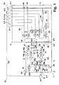
- An in Fig. 1 shown compressed air system 70 has an air acquisition device 1, which is formed of an input block 3, a multi-circuit protection valve block 4 and a control device 5.
- the compressed air system 70 also has consumer circuits 6-1, 6-2, 6-3, 6-4, 6-5 connected to the multi-circuit protection valve block 4 of the air acquisition device 1 and a compressor 8.
- the consumer circuit 6-1 can z. B. for a first service brake circuit, the consumer circuit 6-2 for a second service brake circuit, 6-3 be provided for a parking brake / trailer brake system, 6-4, 6-5 and 6-6 for other consumer groups.
- the compressor 8 is connected to a pneumatic compressor port 3-1 of the input block 3.
- the input block 3 further includes pneumatic ports 3-2 and 3-3 which are connected to respective pneumatic ports 4-2 and 4-3 of the multi-circuit protection valve block 4. Furthermore, a pneumatic input port 8-1 of the compressor 8 for switching off the compressor 8 when compressed air is applied (OFF signal) to a compressed-air outlet 4-1 of the multi-circuit protection valve block is connected.
- the input block 3 serves in particular as a dryer block and has a first air dryer 10 with upstream filter 9 and a second air dryer 12 with upstream filter 11.
- the filters 9, 11 can also be integrated in the air dryer 10, 12, or the air dryer are constructed in a conventional manner as a dryer cartridges with filter. However, it is also possible to use dryer cartridges with a downstream filter or without a filter.
- a first switching valve 14 and a second switching valve 16 are connected, which are both formed in this embodiment as pneumatically driven 3/2-way valves.
- the first filter 9 is connected to the first switching valve 14.
- the second filter 11 is connected to the second switching valve 16, so that depending on the switching position of the switching valves 14, 16 of the respective air dryer 10, 12 is connected to the compressor port 3-1 or separated therefrom.
- a pressure limiter 25 is connected to - in a conventional manner - to limit a load due to excessive pressure.
- the air dryer 10, 12 are thus connected in the illustrated embodiment with their dryer inputs 10a, 12a to the respective filter 9, 11.
- a first delivery area 37 and a second delivery area 38 connect to which in turn a first delivery check valve 17 and a second delivery check valve 18 are connected, which open at compressed air from the respective dryer outlet 10b and 12b the dryer outputs 10b, 12b to a common delivery line 20, which is connected to the pneumatic port 3-2 of the input block 3.
- a first regeneration check valve 22 is connected to the first dryer outlet 10b via a first throttle 21 in such a way that it blocks from the first conveyor region 37 or from the first dryer outlet 10b when compressed air is applied and opens in the opposite direction, thus enabling regeneration of the first air dryer 10.
- a second regeneration check valve 24 is connected in the reverse direction at the second dryer outlet 12b via a second throttle 23, so that it blocks when the compressed air is supplied from the second dryer outlet 12b.
- the regeneration check valves 22 and 24 are connected to a common regeneration line 26, which in turn is connected to the pneumatic port 3-3 of the input block 3.
- the first dryer outlet 10b of the first air dryer 10 is further connected to the pneumatic control port 16a of the second switching valve 16, so that when the first dryer outlet 10b is pressurized the first delivery check valve 17 opens on the one hand and the second switching valve 16 on the other Fig. 1 shown basic position is switched through in its actuated position.
- the second switching valve 16 connects this connected to the compressor port 3-1 input terminal 16b with its output terminal 16c, to which the second filter is connected.
- the second switching valve 16 blocks its input port 16b and applies its output port 16c (third port) to its exhaust port 16d, which is connected to an output port 29, which in turn is connected to an air outlet 31 via a muffler 30.
- the first switching valve 14 is connected with its pneumatic control port 14a to the output of an electropneumatic Vorschaltventils 32, which is designed as electropneumatic 3/2-way valve and in the rest position shown blocks the input and vented the subsequent control port, however, when electrically controlled his electrical control terminal 32a, the delivery line 20 to the pneumatic control port 14a of the first switching valve 14 sets.
- An electrical control terminal 32a of the Vorschaltventils 32 is controlled by the control device 5 with a switching control signal S1, which is output from a control output 5-1 of the control device 5 according to this embodiment and is received by a signal input 3-5 of the input block 3.
- the control device 5 can also be set directly to the input block 3.
- the first switching valve 14 with an electrical control terminal 14a form, which is then controlled directly by the switching control signal S1.
- the first switching valve 14 connects its first terminal 14b, which is connected to the compressor terminal 3-1, to its output terminal 14c, which is connected to the first filter 9.
- the first switching valve 14 blocks its first input port 14b and in turn places its output port 14c (third port) via the muffler 30 to the compressed air outlet 31.
- a supply line section 34 is connected to the delivery line 20 through the compressed air port 4-2 of the multi-circuit protection valve block 4 and the corresponding pneumatic port 3-2 of the input block.
- the various consumer circuits 6-1 to 6-5 are connected via a multi-circuit protection valve arrangement 36, which is known as such and is formed essentially of overflow valves, pressure relief valves and check valves and a throttle.
- a regeneration valve 40 and a compressor control valve 42 are connected to the supply line region 34. Both valves 40, 42 are designed as electropneumatic 3/2-way valves, which are controlled by the control device 5 by control signals S2, S3.
- the regeneration valve 40 When actuated by a regeneration control signal S2 from the control device 5, the regeneration valve 40 switches and, in its actuated position, connects the supply line region 34 to the compressed air connection 4-3 of the multi-circuit protection valve block 4. is thus connected via the corresponding pneumatic port 3-3 of the input block 3 to the regeneration line 26. Accordingly, the compressor control valve 42, when driven by the electric compressor control signal S3, connects the supply line section 34 to the compressed air output 4-1, so that the compressor 8 is controlled by the pneumatic control signal S4, i. Compressed air is switched off at the pneumatic control input 8-1 or switched to an idle position without compressed air supply.
- the compressor 8 is turned on and thus acts on the compressor port 3-1 with compressed air.
- the compressed air through the opened first switching valve 14 and the opened second switching valve 16 each to the filters 9, 11 and through the air dryer 10, 12 promoted.
- pressure is subsequently also applied to the connected pneumatic control input 16a of the second switching valve 16 via the first dryer outlet 10b, so that it is switched through and blocks its input connection 16b.
- the second air dryer 12 is subsequently vented via the output line 29, the muffler 30 and the air outlet 31.
- compressed air continues to be applied via the first air dryer 10 and the first delivery check valve 17 to the delivery line 20 and thus to the supply line 34, so that the air acquisition device 1 is in a first delivery operation and accordingly the connected consumer circuits 6-1 to 6-5 supplied with compressed air.
- the regeneration valve 40 and the compressor valve 42 lock first.
- the second switching valve 16 is switched and thus the second dryer inlet 12a is placed on the output line 29, the second dryer 12 is regenerated and air over the second Regeneration check valve 24, the second throttle 23, the second delivery area 38, the second dryer 12 with filter 11, the second switching valve 16, the output line 29 and the muffler 30 to the air outlet 31 output.
- the second switching valve 16 switches back to its normal position, so that the second dryer inlet 12a is acted upon by the further conveying compressor 8 via the filter 11 and the opened second switching valve 16 with compressed air.
- a second delivery mode takes place, in which compressed air via the second dryer 12, the second delivery check valve 18 is placed on the delivery line 20.
- no first regeneration of the first dryer 10 takes place since there is no pressure in the regeneration line 26.
- the second conveying operation is terminated by the switching control signal S1 is no longer output, and the Vorschaltventil 32 thus switches back, after which also the first switching valve 14 switches back to its normal position, so that the dryer 10 is in turn supplied with compressed air and its dryer outlet 10b the second switching valve 16 turns on and thus blocks the delivery operation by the second dryer 12.
- the second conveying mode is switched to the first conveying mode.
- pressure sensors 50, 51 are connected or formed as part of the control device 5, which regulates the air pressure, e.g. in the load circuits 6-1 and 6-2 (e.g., service brake circuits I and II).
- Switching off the compressor 8 is possible both from the first delivery operation as well as from the second delivery operation out.
- the compressor 8 When the compressor 8 is turned off, initially in the first delivery mode in the first delivery region 37, ie, at the first dryer outlet 10b, pressure continues to prevail, so that the second switching valve 16 remains initially switched through.
- Fig. 2 are identical or similar components and elements with the same or similar reference numerals.
- the entire compressed air system 70 with the compressor 8 and the consumer circuits 6-1 to 6-5 is no longer shown, but only the air acquisition device 1 with input block 103 and multi-circuit protection valve block 104.
- a governor control valve 56 is provided in the input block 103, which is designed as a pneumatic 3/2-way valve with two pneumatic control inputs 56a and 56b and is connected to the feed line 20 with an input port and a pneumatic control input 56a. In its spring-biased basic position it locks the input port, in its actuated position it puts the delivery line 20 to a compressed air control output 3-4 of the input block 103, which serves to control the compressor 8. Accordingly, in the multi-circuit protection valve block 104 no compressed air outlet 4-1 as in the embodiment of Fig. 1 intended.
- Fig. 3 shows a further embodiment in which instead of the regeneration check valves, a 2/2-regeneration check valve 60 is set with a pneumatic control input 60a adjacent to a common throttle 62.
- the path of regeneration check valve 60 and throttle 62 is connected between the two dryer outputs 10b and 12b and thus between the delivery regions 37, 38, ie parallel to the path from the two delivery check valves 17, 18.
- the regeneration check valve 60 In the default state is the regeneration check valve 60 open, so that a regeneration by connecting the conveyor regions 37, 38 via the throttle 62 can be carried out alternately in the other conveying operation, ie in the first conveying operation, a second regeneration and vice versa.
- the pneumatic control input 60a of the check valve 60 is driven by the compressor control valve 42 via pneumatic ports 4-4 and 3-8.
- the regeneration shut-off valve 60 is actuated, so that only in a conveying mode, but not when switched off Compressor can be a regeneration. According to this embodiment, regeneration thus takes place only in the delivery phases from one air dryer to the other.
- the pilot valve 32 is provided here in the multi-circuit protection valve block 204.
- FIG. 3 . 4 . 5 Here is the second switching valve 16 with the same functionality as in Fig. 1 . 2 due to a staggered line arrangement symmetrically mirrored to Fig. 1 . 2 shown. Furthermore, the representations z. B. the multi-circuit protection valve blocks 4, 104, 204, 304, 404, 504 partially schematically, with z. B. the multi-circuit protection valve blocks 4, 304, 504 correspond.
- the multi-circuit protection valve block 4 is off Fig. 1 intended.
- a 2/2-way shut-off valve 65 is provided in the input block 303, the electrical control input 65a is controlled by an electrical signal input 3-6 from the regeneration signal S2. In the rest position shown, it locks and thus separates the regeneration check valves 22 and 24 from the delivery line 20. Accordingly Fig. 1 Chokes 21 and 23 are provided behind the regeneration check valves 22 and 24.
- both dryer outputs 10b and 12b are thus supplied with regeneration air from the regeneration line 26 by the delivery line 20.
- the pneumatic pilot valve 32 is arranged in the multi-circuit protection valve block 4; ie basically the same structure as the multi-circuit protection valve block 4 off Fig. 1
- this is another use of the valves.
- the control device 5 is connected to the input block 403, in which the feed valve 32 for receiving the switching control signal S1 of the control device 5 and is provided for pressurizing the pneumatic control input 14a of the first switching valve 14, also serving as a regeneration valve compressor control valve 42, which in turn turns on receipt of the regeneration control signal S2 from the shown, blocking rest position and thereby the delivery line 20 and places the supply line region 34 on the pneumatic control input 60a of the 2/2-way regeneration shut-off valve 60 and thus switches it into its blocking position; Furthermore, the compressed air control output 3-4 of the input block 403 is pressurized with compressed air.
- the functionality thus corresponds to the embodiment of the Fig. 3 However, there are the valves 32, 42 provided in the input block 403 and the controller 5 connected to this.
- Fig. 6 shows an embodiment in which instead of the two 3/2-way valves of Fig. 1 to 5 in the input block 503, a 4/2-way switching valve 216 is provided, the pneumatic control input 216a to the electropneumatic Vorschaltventil 32 is connected.
- the 4/2-way switching valve 216 thus replaces the two switching valves 16, 14 of the Fig. 1 , Opposite z. B. the EP 199948 A1
- This circuit also differs in particular by the compressor control valve 42 in the multi-circuit protection valve block 4, whereby a demand-driven control of the compressor 8 and thus the delivery phases is possible.
- two regeneration paths, each with a check valve 22, 24 and a respective throttle 21, 23 are provided.
- the first and second regeneration operation are also possible with the vehicle switched off and thus with the compressor switched off and with compressed air still stored in the storage area in order to use it for regeneration (power down purge);
- the regeneration valve is to be controlled by the control device. According to the invention, such a power-down-purge operation is successively possible as the first and second regeneration operation.
- valves eg solenoid valves
Abstract
Die Erfindung betrifft eine Luftbeschaffungsvorrichtung (1) für ein Druckluft-system (70) eines Fahrzeuges, wobei die Luftbeschaffungsvorrichtung (1) aufweist: einen Kompressoranschluss (3-1) zum Anschluss eines Kompressors (8), eine erste Trocknereinrichtung (10) und eine zweite Trocknereinrichtung (12), eine Schaltventileinrichtung (14, 16) zum Anschließen der ersten Trocknereinrichtung (10) an den Kompressoranschluss (3-1) für einen ersten Förderbetrieb oder der zweiten Trocknereinrichtung (12) an den Kompressoran-schluss (3-1) für einen zweiten Förderbetrieb, einen Vorratsbereich (20, 34) zum Speichern oder Aufnehmen oder zum Verteilen und Weiterleiten von durch die Trocknereinrichtungen (10, 12) geförderter Druckluft, eine Regenerationsventileinrichtung (40, 22, 24) zum Regenerieren der Trocknereinrichtungen (10, 12) durch Verbinden des Vorratsbereichs (34) mit einem Trocknerausgang (10b, 12b) der ersten Trocknereinrichtung (10) oder zweiten Trocknereinrichtung (12), wobei die Schaltventileinrichtung (32, 14) und die Regenerationsventileinrich-tung (40, 22, 24) jeweils ein elektrisch ansteuerbares Magnetventil (32, 40) aufweisen. Hierbei ist vorgesehen, dass die Luftbeschaffungsvorrichtung ein elektrisch ansteuerbares Kompressor-Steuerventil zur direkten oder indirekten Ansteuerung des Kompressors (8) aufweist.The invention relates to an air acquisition device (1) for a compressed air system (70) of a vehicle, the air acquisition device (1) comprising: a compressor port (3-1) for connecting a compressor (8), a first dryer device (10) and a second dryer device (12), a switching valve device (14, 16) for connecting the first drying device (10) to the compressor port (3-1) for a first conveying operation or the second drying device (12) to the compressor port (3-1) for a second conveying operation, a storage area (20, 34) for storing or receiving or for distributing and forwarding compressed air conveyed by the drying devices (10, 12), a regeneration valve device (40, 22, 24) for regenerating the dryer devices (10, 12) by connecting the storage region (34) to a dryer outlet (10b, 12b) of the first dryer device (10) or second dryer device (12), wherein the switching valve means (32, 14) and the Regenerationsventileinrich-device (40, 22, 24) each having an electrically controllable solenoid valve (32, 40). It is provided that the air acquisition device has an electrically controllable compressor control valve for direct or indirect control of the compressor (8).
Description
Die Erfindung betrifft eine Luftbeschaffungsvorrichtung für ein Druckluftsystem eines Fahrzeugs, insbesondere eines Nutzfahrzeuges, sowie ein derartiges Druckluftsystem.The invention relates to an air acquisition device for a compressed air system of a vehicle, in particular a commercial vehicle, as well as such a compressed air system.
Luftbeschaffungsvorrichtungen in Druckluftsystemen von Fahrzeugen werden im Allgemeinen an den Kompressor des Fahrzeuges angeschlossen und dienen dazu, die vom Kompressor geförderte Luft zu trocknen, im Allgemeinen ergänzend zu filtern, und verschiedenen Verbraucherkreisen zur Verfügung zu stellen. Sie weisen einen Trocknerblock bzw. eine Luftaufbereitungseinrichtung auf, die von einem Kompressor geförderte Druckluft trocknet und an einen nachgeordneten Versorgungsbereich mit einer Mehrkreisschutzventileinrichtung zum Schutz mehrerer angeschlossener Verbraucherkreise ausgibt. Weiterhin ermöglichen Luftbeschaffungsvorrichtungen eine Regenerationsphase, in der ein Teil der geförderten Luft aus dem Versorgungsbereich unter Entspannung mittels einer Drossel durch die Trocknereinrichtung zurückgeführt wird, um die in der Trocknereinrichtung gesammelte Feuchtigkeit wieder durch einen Druckluftauslass auszugeben.Air handling devices in compressed air systems of vehicles are generally connected to the compressor of the vehicle and serve to dry the air supplied by the compressor, generally in addition to filtering, and to provide various consumer circuits. They have a dryer block or an air treatment device which dries compressed air conveyed by a compressor and outputs it to a downstream supply area with a multi-circuit protection valve device for protecting a plurality of connected consumer circuits. Furthermore, air supply devices allow a regeneration phase in which a portion of the conveyed air from the supply area is recirculated under relaxation by means of a throttle through the dryer device to output the moisture collected in the dryer device again by a compressed air outlet.
Neben Einkammer-Lufttrocknern mit lediglich einem Trockner sind auch Zweikammer-Lufttrockner bekannt, bei denen zwei Trockner parallel bzw. in parallelen Förderpfaden angeordnet sind, so dass alternativ ein erster Förderbetrieb durch den ersten Lufttrockner und ein zweiter Förderbetrieb durch den zweiten Lufttrockner ermöglicht wird. Bei derartigen Zweikammer- Lufttrocknern ist grundsätzlich eine Regeneration der nicht im Förderbetrieb befindlichen Trocknereinrichtungen möglich, während die andere Trocknereinrichtung fördert.In addition to single-chamber air dryers with only one dryer and two-chamber air dryer are known in which two dryers are arranged in parallel or in parallel conveying paths, so that alternatively a first conveying operation by the first air dryer and a second conveying operation is made possible by the second air dryer. In such two-chamber air dryers is basically a regeneration of not located in the production operation Dryer facilities possible while the other dryer device promotes.
Die
Die
Die
Der Erfindung liegt die Aufgabe zugrunde, eine Luftbeschaffungsvorrichtung zu schaffen, die ein effizientes Regenerieren der einzelnen Trockner ermöglicht, sowie ein Druckluftsystem mit einer derartigen Luftbeschaffungsvorrichtung.The invention has for its object to provide an air acquisition device, the efficient regeneration of the individual dryer allows, as well as a compressed air system with such an air acquisition device.
Diese Aufgabe wird durch eine Luftbeschaffungsvorrichtung nach Anspruch 1 gelöst. Die Unteransprüche beschreiben bevorzugte Weiterbildungen. Weiterhin ist ein Druckluftsystem mit einer derartigen Luftbeschaffungsvorrichtung vorgesehen.This object is achieved by an air acquisition device according to
Somit ist ein elektrisch ansteuerbares Kompressor-Steuerventil zur direkten oder indirekten Ansteuerung des Kompressors vorgesehen.Thus, an electrically controllable compressor control valve for direct or indirect control of the compressor is provided.
Eine direkte Ansteuerung des Kompressors kann durch einen pneumatischen Steuereingang am Kompressor vorgesehen sein, insbesondere zum Ausschalten bei Druckluftbeaufschlagung. Eine indirekte Ansteuerung des Kompressors kann z. B. durch eine ansteuerbare Kompressorkupplung realisiert werden.A direct control of the compressor can be provided by a pneumatic control input to the compressor, in particular for switching off when compressed air. An indirect control of the compressor can, for. B. be realized by a controllable compressor clutch.
Somit können durch drei elektrisch ansteuerbare Pneumatikventile, insbesondere Magnet-Ventile, vielfältige Funktionen einer Zweikammer-Trocknervorrichtung realisiert werden, insbesondere mit geringem Hardware-Aufwand. Hierbei ist eine volle Funktionalität beider Trocknerpfade, sowohl der zwei Förderbetriebe als auch der Regenerationsbetriebe vorgesehen.Thus, by three electrically controllable pneumatic valves, in particular solenoid valves, various functions of a two-chamber dryer apparatus can be realized, in particular with little hardware effort. Here, a full functionality of both dryer paths, both of the two production companies and the regeneration operations is provided.
Somit können drei Funktionalitäten bedarfsgerecht gesteuert werden:
- a) der Wechsel zwischen den beiden Förderbetrieben, d.h. durch den ersten oder zweiten Trockner bzw. Trocknerkartusche;
- b) die Regeneration und
- c) die Kompressorsteuerung.
- a) the change between the two conveyor operations, ie by the first or second dryer or dryer cartridge;
- b) the regeneration and
- c) the compressor control.
Hierbei kann z. B. eine bevorzugte Nutzung einer Kartusche durch entsprechende Software-Steuerung erfolgen, so dass diese gezielt schneller verschmutzt und auszutauschen ist.This z. B. a preferred use of a cartridge by appropriate software control done so that this targeted faster polluted and exchange.
Die Schaltventileinrichtung zum Umschalten zwischen den Trocknern weist gemäß einigen Ausführungsformen zwei separate Schaltventile auf, die vorzugsweise als 3/2-Wege-Ventile ausgebildet sein können. Hierbei ist insbesondere eine Ausbildung als pneumatische 3/2-Schaltventile möglich, so dass diese im Wesentlichen gleich und somit kostengünstig ausbildbar sind.The switching valve device for switching between the dryers, according to some embodiments, two separate switching valves, which may be preferably formed as 3/2-way valves. In this case, in particular, a design as a pneumatic 3/2-way valves is possible, so that they are substantially the same and thus inexpensive to be formed.
Gemäß dieser Ausführung wird vorzugsweise bewusst eine unsymmetrische Ausbildung gewählt, bei der die Umschaltventile unterschiedlich angesteuert werden. So kann insbesondere das zweite Schaltventil zum Freigeben/ Sperren sowie Regenerieren des zweiten Lufttrockners in Abhängigkeit des Trocknerausgangs des ersten Trockners angesteuert werden; vorzugsweise ist der erste Trocknerausgang direkt an den pneumatischen Steuereingang des zweiten Umschaltventils angeschlossen. Das erste Schaltventil wird hingegen vorzugsweise nicht von dem zweiten Trocknerausgang, sondern in Abhängigkeit eines Umschalt-Steuersignals geschaltet, das vorteilhafterweise direkt oder indirekt von der Steuereinrichtung ausgegeben wird. Diese Ansteuerung kann direkt durch Ausbildung des ersten Schaltventils mit elektrischem Steuereingang oder vorzugsweise auch mit einem vorgeschaltetem elektropneumatischen Vorschaltventil (Vorsteuerventil) erfolgen, das von der Steuereinrichtung elektrisch angesteuert wird und als Relaisventil zur Ausgabe eines pneumatischen Schaltdrucks dient.According to this embodiment, it is preferable to deliberately choose an asymmetrical design in which the change-over valves are controlled differently. Thus, in particular, the second switching valve for releasing / blocking and regenerating the second air dryer can be activated as a function of the dryer output of the first dryer; Preferably, the first dryer outlet is connected directly to the pneumatic control input of the second changeover valve. The first switching valve, however, is preferably not switched by the second dryer output, but in response to a switching control signal, which is advantageously output directly or indirectly from the control device. This control can be done directly by forming the first switching valve with electrical control input or preferably also with an upstream electro-pneumatic pilot valve (pilot valve), which is electrically controlled by the control device and serves as a relay valve for outputting a pneumatic switching pressure.
Hierbei kann z.B. das Vorsteuerventil entweder im Grundzustand sperren und somit bei Aufnahme des elektrischen Umschalt-Steuersignals öffnen und den pneumatischen Steuerdruck an das zweite Schaltventil ausgeben. Alternativ hierzu kann das elektropneumatische Vorsteuerventil jedoch auch zur Invertierung des Steuersignals der Steuereinrichtung dienen, d.h. das erste Schaltventil ist im Grundzustand offen und wird durch das im unbetätigten Grundzustand sperrende elektropneumatische Vorsteuerventil bei dessen elektrischer Betätigung durchgeschaltet.In this case, for example, the pilot valve either lock in the ground state and thus open when receiving the electrical switching control signal and output the pneumatic control pressure to the second switching valve. Alternatively, however, the electropneumatic pilot valve can also be used for inverting the control signal of the control device, ie the The first switching valve is open in the ground state and is switched through by the in the unactuated basic state blocking electropneumatic pilot valve during its electrical actuation.
Bei einer derartigen Ausbildung wird zwar zugelassen, dass beim Starten des Kompressors zunächst gegebenenfalls in einer Anfangsphase kurzzeitig beide Trockner gleichzeitig im Förderbetrieb sind, bis der Trocknerausgang des ersten Lufttrockners die zweite Schalteinrichtung schaltet. Es wird jedoch erkannt, dass derartige Phasen relativ kurzzeitig und daher nicht relevant sind.In such a configuration is admittedly admitted that when starting the compressor, if necessary, initially in an initial phase both dryers are simultaneously in the conveying mode until the dryer outlet of the first air dryer switches the second switching device. However, it is recognized that such phases are relatively short term and therefore not relevant.
Erfindungsgemäß ist ein wahlweiser Betrieb möglich, insbesondere - der erste oder zweite Förderbetrieb, bei Einsatz von mehr als zwei Lufttrockner auch entsprechend weitere Förderbetriebe bzw. Trocknerbetriebe, - ein erster Regenerationsbetrieb des ersten Trockners oder ein zweiter Regenerationsbetrieb des zweiten Trockners sowohl bei Förderbetrieb durch jeweils den anderen Trockner als auch bei Ruhebetrieb (ausgeschalteter Kompressor) oder Leerlaufbetrieb des Kompressors möglich.According to the invention, an optional operation is possible, in particular - the first or second conveying operation, when using more than two air dryer according to further Förderbetriebe or dryer operations, - a first regeneration operation of the first dryer or a second regeneration operation of the second dryer both in conveying operation by each den other dryers as well as in idle mode (switched off compressor) or idle operation of the compressor possible.
Ein erster und zweiter Regenerationsbetrieb sind auch bei ausgeschaltetem Fahrzeug und somit ausgeschaltetem Kompressor und noch im Vorratsbereich gespeicherter Druckluft möglich, um diese zur Regeneration zu nutzen (power down purge); hierzu ist das Regenerationsventil von der Steuereinrichtung anzusteuern. Ein derartiger power down purge- Betrieb ist erfindungsgemäß sukzessiv als erster und zweiter Regenerationsbetrieb, grundsätzlich aber auch parallel durch beide Trockner möglich.A first and second regeneration operation are also possible with the vehicle switched off and thus the compressor switched off and compressed air still stored in the storage area in order to use it for regeneration (power down purge); For this purpose, the regeneration valve is to be controlled by the control device. According to the invention, such a power-down-purge operation is successively possible as the first and second regeneration operation, but in principle also in parallel through both dryers.
Weiterhin wird aufeinanderfolgend ein erster und zweiter (oder zweiter und erster) Förderbetrieb ohne zwischengeschaltete oder parallel verlaufende Regenerationen ermöglicht; dies kann insbesondere auch zur Schubphasennutzung des Fahrzeugs dienen, um in Schubphasen den Kompressor an den Fahrzeug-Motor anzukoppeln und durch die Trockner Luft zu fördern, ohne in den Schubphasen Zeit für Regenerationen zu verlieren.Furthermore, successively a first and second (or second and first) conveying operation without intermediate or parallel regenerations possible; This can also be used in particular for the shear phase use of the vehicle to the compressor in coasting phases To couple the vehicle engine and to promote air through the dryers, without losing time for regeneration in the deceleration phases.
Auch ist es erfindungsgemäß möglich, gezielt die Trockner unsymmetrisch oder ungleichmäßig zu belasten, um z. B. eine Trocknerkartusche innerhalb eines Wartungsintervalls stärker zu belasten, so dass diese auszutauschen ist, die andere Trocknerkartusche hingegen - falls der Betrieb bzw. der Förderbedarf dies zulässt - nur wenig zu belasten, so dass diese gegebenenfalls nicht auszutauschen ist.It is also possible according to the invention, targeted to load the dryer asymmetrically or non-uniformly, for. B. a dryer cartridge within a maintenance interval to load more heavily, so that it is exchanged, the other dryer cartridge, however, if the operation or the need for support allows this only slightly, so this may not be replaced.
Erfindungsgemäß sind unterschiedliche Ausführungsformen möglich, bei denen z.B. die elektrisch angesteuerten Magnetventile wahlweise im Eingangsblock bzw. Lufttrocknerblock oder in einem nachgeschalteten Mehrkreisschutzventil-Block vorgesehen sind, wobei auch die Steuereinrichtung unterschiedlich angeordnet sein kann.According to the invention, different embodiments are possible in which e.g. the electrically controlled solenoid valves are provided either in the input block or air dryer block or in a downstream multi-circuit protection valve block, wherein the control device may be arranged differently.
Gemäß einer Ausführungsform kann ein zusätzlicher Governor bzw. ein Governor-Steuerventil vorgesehen sein; dies bietet den Vorteil, dass auch bei Ausfall der Elektrik / Elektronik die Luftaufbereitung in einem "Notlauf"-Modus arbeitet, bei dem unter erhöhtem Luftverbrauch die Grundfunktionen Luftförderung und Trocknung gegeben sind. Im "Notlauf"-Modus sorgt der Governor vorzugsweise dafür, dass bei einem definierten Abschaltdruck im System der Kompressor abgeschaltet und die Regeneration eingeleitet wird.According to one embodiment, an additional governor or governor control valve may be provided; This offers the advantage that even if the electrics / electronics fail, the air treatment operates in an "emergency mode", in which the basic functions of air extraction and drying are given under increased air consumption. In "emergency mode", the governor preferably ensures that the compressor is switched off and regeneration is initiated at a defined switch-off pressure in the system.
Ein weiterer Vorteil liegt darin, dass der Kompressor abgeschaltet werden kann, ohne dass Druck aus der Leitung vom Kompressor und aus der Kartusche entweicht. Damit ist bei Wiedereinschalten des Kompressors die Leitung noch mit Druckluft befüllt, und es kann sofort ins System gefüllt werdenAnother advantage is that the compressor can be switched off without pressure from the line escaping from the compressor and the cartridge. Thus, when the compressor is restarted, the line is still filled with compressed air, and it can be filled immediately into the system
Weiterhin können Intervalle zum Kartuschen-Wechsel (Austausch nach Abnutzung) der ersten und zweiten Kartusche (in der Werkstatt) unabhängig voneinander sein. Es ist hierbei eine Diagnose oder Fahrermitteilung über den Kartuschenstatus möglich.Furthermore, intervals for changing cartridges (replacement after wear) of the first and second cartridges (in the workshop) may be independent of each other. In this case, a diagnosis or driver message about the cartridge status is possible.
Die Erfindung wird im Folgenden anhand der beiliegenden Zeichnungen an einigen Ausführungsformen erläutert. Es zeigen:
- Fig. 1
- ein elektropneumatisches Schaltschema eines Druckluftsystems gemäß einer ersten Ausführungsform mit am Mehrkreisschutzventil-Block angeschlossener Steuereinrichtung;
- Fig. 2
- ein elektropneumatisches Schaltschema gemäß einer weiteren Ausführungsform;
- Fig. 3
- ein elektropneumatisches Schaltschema gemäß einer dritten Ausführungsform;
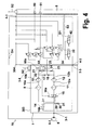
- Fig. 4
- ein elektropneumatisches Schaltschema gemäß einer vierten Ausführungsform;
- Fig. 5
- ein elektropneumatisches Schaltschema eines Druckluftsystems gemäß einer fünften Ausführungsform mit Anordnung der Steuereinrichtung am Eingangsblock; und
- Fig. 6
- ein elektropneumatisches Schaltschema eines Druckluftsystems gemäß einer sechsten Ausführungsform mit 4/2-Wegeventil.
- Fig. 1
- an electropneumatic circuit diagram of a compressed air system according to a first embodiment with connected to the multi-circuit protection valve block controller;
- Fig. 2
- an electropneumatic circuit diagram according to another embodiment;
- Fig. 3
- an electropneumatic circuit diagram according to a third embodiment;
- Fig. 4
- an electropneumatic circuit diagram according to a fourth embodiment;
- Fig. 5
- an electro-pneumatic circuit diagram of a compressed air system according to a fifth embodiment with arrangement of the control device on the input block; and
- Fig. 6
- an electro-pneumatic circuit diagram of a compressed air system according to a sixth embodiment with 4/2-way valve.
Ein in
Der Kompressor 8 ist an einen pneumatischen Kompressoranschluss 3-1 des Eingangsblocks 3 angeschlossen. Der Eingangsblock 3 weist weiterhin pneumatische Anschlüsse 3-2 und 3-3 auf, die an entsprechende pneumatische Anschlüsse 4-2 und 4-3 des Mehrkreisschutzventil-Blocks 4 angeschlossen sind. Weiterhin ist ein pneumatischer Eingangsanschluss 8-1 des Kompressors 8 zum Abschalten des Kompressors 8 bei Druckluftbeaufschlagung (OFF-Signal) an einen Druckluftausgang 4-1 des Mehrkreisschutzventil-Blocks angeschlossen.The
Der Eingangsblock 3 dient insbesondere als Trockner-Block und weist einen ersten Lufttrockner 10 mit vorgeschaltetem Filter 9 sowie einen zweiten Lufttrockner 12 mit vorgeschaltetem Filter 11 auf. Die Filter 9, 11 können hierbei auch in den Lufttrockner 10, 12 integriert sein, bzw. die Lufttrockner sind in üblicher Weise als Trocknerkartuschen mit Filter aufgebaut. Es können aber auch Trocknerkartuschen mit nachgeschaltetem Filter oder ohne Filter verwendet werden.The
An den Kompressoranschluss 3-1 sind ein erstes Schaltventil 14 und ein zweites Schaltventil 16 geschaltet, die bei dieser Ausführungsform beide als pneumatisch angesteuerte 3/2-Wege-Ventile ausgebildet sind. An das erste Schaltventil 14 ist der erste Filter 9 angeschlossen. Entsprechend ist an das zweite Schaltventil 16 der zweite Filter 11 angeschlossen, so dass je nach Schaltstellung der Schaltventile 14, 16 der jeweilige Lufttrockner 10, 12 an den Kompressoranschluss 3-1 angeschlossen oder hiervon getrennt ist. An den Kompressoranschluss 3-1 ist weiterhin vorzugsweise ein Druckbegrenzer 25 angeschlossen, um - in an sich bekannter Weise - eine Belastung durch zu hohen Druck zu begrenzen. Die Lufttrockner 10, 12 sind in der dargestellten Ausführungsform mit ihren Trocknereingängen 10a, 12a somit an das jeweilige Filter 9, 11 angeschlossen. An ihre Trocknerausgänge 10b und 12b schließen sich ein erster Förderbereich 37 und ein zweiter Förderbereich 38 an, an die wiederum ein erstes Förder- Rückschlagventil 17 und ein zweites Förder-Rückschlagventil 18 angeschlossen sind, die bei Druckluftbeaufschlagung vom jeweiligen Trocknerausgang 10b und 12b aus öffnen und die Trocknerausgänge 10b, 12b an eine gemeinsame Förderleitung 20 legen, die an den pneumatischen Anschluss 3-2 des Eingangsblocks 3 angeschlossen ist.To the compressor port 3-1, a
Weiterhin ist an den ersten Trocknerausgang 10b über eine erste Drossel 21 ein erstes Regenerations-Rückschlagventil 22 derartig angeschlossen, dass es bei Druckluftbeaufschlagung vom ersten Förderbereich 37 bzw. vom ersten Trocknerausgang 10b sperrt und in Gegenrichtung öffnet und somit eine Regeneration des ersten Lufttrockners 10 ermöglicht. Entsprechend ist an dem zweiten Trocknerausgang 12b über eine zweite Drossel 23 ein zweites Regenerations-Rückschlagventil 24 in Sperrrichtung geschaltet, so dass es bei Druckluftbeaufschlagung vom zweiten Trocknerausgang 12b her sperrt. Die Regenerations-Rückschlagventile 22 und 24 sind an eine gemeinesame Regenerationsleitung 26 angeschlossen, die wiederum an den pneumatischen Anschluss 3-3 des Eingangsblocks 3 angeschlossen ist.Furthermore, a first
Der erste Trocknerausgang 10b des ersten Lufttrockners 10 ist weiterhin an den pneumatischen Steueranschluss 16a des zweiten Schaltventils 16 angeschlossen, so dass bei Luftbeaufschlagung des ersten Trocknerausgangs 10b zum einen das erste Förder-Rückschlagventil 17 öffnet und zum anderen das zweite Schaltventil 16 von der in
Das erste Schaltventil 14 ist mit seinem pneumatischen Steueranschluss 14a an den Ausgang eines elektropneumatischen Vorschaltventils 32 angeschlossen, das als elektropneumatisches 3/2-Wege-Ventil ausgebildet ist und in der gezeigten Ruhestellung den Eingang sperrt und den nachfolgenden Steueranschluss entlüftet, hingegen bei elektrischer Ansteuerung seines elektrischen Steueranschlusses 32a die Förderleitung 20 an den pneumatischen Steueranschluss 14a des ersten Schaltventils 14 legt. Ein elektrischer Steueranschluss 32a des Vorschaltventils 32 wird von der Steuereinrichtung 5 mit einem Umschalt-Steuersignal S1 angesteuert, das gemäß dieser Ausführungsform von einem Steuerausgang 5-1 der Steuereinrichtung 5 ausgegeben wird und von einem Signaleingang 3-5 des Eingangsblocks 3 aufgenommen wird. Grundsätzlich kann die Steuereinrichtung 5 auch direkt an den Eingangsblock 3 gesetzt werden. Weiterhin ist es möglich, alternativ zu der Verwendung des pneumatischen Vorschaltventils 32 das erste Schaltventil 14 mit einem elektrischen Steueranschluss 14a auszubilden, der dann direkt von dem Umschalt- Steuersignal S1 angesteuert wird. In der gezeigten Grundstellung verbindet das erste Schaltventil 14 seinen an den Kompressoranschluss 3-1 angeschlossenen ersten Anschluss 14b mit seinem Ausgangsanschluss 14c, der an das erste Filter 9 angeschlossen ist. In seiner betätigten Stellung sperrt das erste Schaltventil 14 seinen ersten Eingangsanschluss 14b und legt seinen Ausgangsanschluss 14c (dritter Anschluss) wiederum über den Schalldämpfer 30 an den Druckluftauslass 31.The
Im Mehrkreisschutzventil-Block 4 ist ein Versorgungsleitungsbereich 34 über den Druckluftanschluss 4-2 des Mehrkreisschutzventil-Blocks 4 und den entsprechenden pneumatischen Anschluss 3-2 des Eingangsblocks an die Förderleitung 20 angeschlossenen. An dem Versorgungsleitungsbereich 34 sind über eine Mehrkreisschutzventil-Anordnung 36, die als solche bekannt ist und im Wesentlichen aus Überströmventilen, Druckbegrenzungsventilen und Rückschlagventilen sowie einer Drossel ausgebildet ist, die verschiedenen Verbraucherkreise 6-1 bis 6-5 angeschlossen. Weiterhin sind an den Versorgungsleitungsbereich 34 ein Regenerationsventil 40 und ein Kompressor-Steuerventil 42 angeschlossen. Beide Ventile 40, 42 sind als elektropneumatische 3/2-Wege-Ventile ausgebildet, die durch Steuersignale S2, S3 von der Steuereinrichtung 5 angesteuert werden. In seiner gezeigten Grundstellung sperrt das Regenerationsventil 40 den Versorgungsleitungsbereich 34. Bei Ansteuerung durch ein Regenerations-Steuersignal S2 von der Steuereinrichtung 5 schaltet das Regenerationsventil 40 durch und verbindet in seiner betätigten Stellung den Versorgungsleitungsbereich 34 mit dem Druckluftanschluss 4-3 des Mehrkreisschutzventil-Blocks 4, der somit über den entsprechenden pneumatischen Anschluss 3-3 des Eingangsblocks 3 an die Regenerationsleitung 26 angeschlossen wird. Entsprechend verbindet das Kompressor-Steuerventil 42 bei Ansteuerung durch das elektrische Kompressor-Steuersignal S3 den Versorgungsleitungsbereich 34 an den Druckluftausgang 4-1, so dass der Kompressor 8 über das pneumatische Steuersignal S4, d.h. Druckluftbeaufschlagung am pneumatischen Steuereingang 8-1 ausgeschaltet wird bzw. in eine Leerlaufstellung ohne Druckluftförderung geschaltet wird.In the multi-circuit protection valve block 4, a
Nachfolgend werden die verschiedenen Betriebsmodi und Einstellungen der Luftbeschaffungsvorrichtung 1 der
Im ersten Förderbetrieb erfolgt somit keine Druckluftförderung über den zweiten Trockner 12. Es ist jedoch im ersten Förderbetrieb, d.h. bei S1=0, S3=0, eine zweite Regeneration möglich, d.h. S1=0, S3=0, S2=1: Indem S2=1 ausgegeben wird, schaltet das zweite Regenerationsventil 40 durch und legt den Druck des Versorgungsleitungsbereichs 34 über die Anschlüsse 4-3 und 3-3 auf die Regenerationsleitung 26 und somit an die Regenerations-Rückschlagventile 22 und 24, an deren anderer Seite jeweils der Druck des ersten bzw. zweiten Förderbereichs 37, 38 anliegt. Da im ersten Förderbetrieb der erste Förderbereich 37 unter dem Druck des Versorgungsleitungsbereichs 34 steht, öffnet das erste Regenerations-Rückschlagventil 22 nicht. Da der zweite Förderbereich 38 drucklos ist, öffnet das zweite Regenerations-Rückschlagventil 23. Da weiterhin das zweite Schaltventil 16 geschaltet ist und somit der zweite Trocknereingang 12a an die Ausgangsleitung 29 gelegt ist, wird der zweite Trockner 12 regeneriert und Luft über das zweite Regenerations-Rückschlagventil 24, die zweite Drossel 23, den zweiten Förderbereich 38, den zweiten Trockner 12 mitsamt Filter 11, das zweite Schaltventil 16 , die Ausgangsleitung 29 und den Schalldämpfer 30 an den Luftauslass 31 ausgegeben.However, in the first delivery mode there is no compressed air delivery via the
Die Steuereinrichtung 5 schaltet durch Ausgabe des Umschalt- Steuersignals S1, d.h. mit S1= 1, die Luftbeschaffungsvorrichtung 1 von dem ersten Förderbetrieb in einen zweiten Förderbetrieb um, bei dem die Luft über den zweiten Lufttrockner 12 statt den ersten Lufttrockner 10 gefördert wird.The
Durch das Umschalt-Steuersignal S1 wird zunächst das pneumatische Vorschaltventil 32 durchgeschaltet, so dass es den Druck von der Förderleitung 20 und dem Versorgungsleitungsbereich 34 auf den pneumatischen Steuereingang 14a des ersten Schaltventils 14 legt. Der Versorgungsleitungsbereich 34 ist hierbei auch bei z.B. vorübergehend ausgeschaltetem Kompressor 8 durchweg mit hinreichendem Druck versorgt, gegebenenfalls auch über die Mehrkreisschutzventil- Anordnung 36 von den Verbraucherkreisen 6-1, 6-2 und 6-5. Das betätigte erste Schaltventil 14 sperrt somit seinen Eingangsanschluss 14b und legt den ersten Trocknereingang 10a über das erste Filter 9 und die Ausgangsleitung 29 an den Druckluftauslass 31. Somit wird der erste Förderbetrieb über den ersten Trockner 10 beendet. Da der erste Trocknerausgang 10b nunmehr drucklos ist, schaltet das zweite Schaltventil 16 in seine Grundstellung zurück , so dass der zweite Trocknereingang 12a über das Filter 11 und das geöffnete zweite Schaltventil 16 vom weiterhin fördernden Kompressor 8 mit Druckluft beaufschlagt wird. Somit findet ein zweiter Fördermodus statt, bei dem Druckluft über den zweiten Trockner 12, das zweite Förder-Rückschlagventil 18 auf die Förderleitung 20 gelegt wird. Es liegt der Zustand S1=1, S2=0, S3=0 (Kompressor an) vor. Somit findet auch noch keine erste Regeneration des ersten Trockners 10 statt, da in der Regenerationsleitung 26 kein Druck vorliegt.By the switching control signal S1, first the
Der zweite Förderbetrieb wird beendet, indem das Umschalt-Steuersignal S1 nicht mehr ausgegeben wird, und das Vorschaltventil 32 somit zurückschaltet, woraufhin auch das erste Schaltventil 14 in seine Grundstellung zurückschaltet, so dass der Trockner 10 wiederum mit Druckluft beaufschlagt wird und über seinen Trocknerausgang 10b das zweite Schaltventil 16 durchschaltet und somit den Förderbetrieb durch den zweiten Trockner 12 sperrt. Somit wird wiederum vom zweiten Förderbetrieb in den ersten Förderbetrieb umgeschaltet.The second conveying operation is terminated by the switching control signal S1 is no longer output, and the
An die Steuereinrichtung 5 sind Drucksensoren 50, 51 angeschlossen bzw. als Teil der Steuereinrichtung 5 ausgebildet, die den Luftdruck z.B. in den Verbraucherkreisen 6-1 und 6-2 (z.B. Betriebsbremskreise I und II) messen. Wenn die Steuereinrichtung 5 erkennt, dass ein hinreichender Betriebsdruck vorliegt und somit der Förderbetrieb beendet werden kann, gibt sie das Kompressor-Steuersignal S3 aus, d.h. S3=1, so dass das Kompressor-Steuerventil 42 durchschaltet und den Druck im Versorgungsleitungsbereich 34 über den Anschluss 4-2 an den Steuereingang 8-1 des Kompressors 8 anlegt, was ein pneumatisches Steuersignal S4 darstellt.To the
Ein Ausschalten des Kompressors 8 ist sowohl aus dem ersten Förderbetrieb heraus als auch aus dem zweiten Förderbetrieb heraus möglich. Wenn der Kompressor 8 ausgeschaltet wird, liegt im ersten Förderbetrieb im ersten Förderbereich 37, d.h. am ersten Trocknerausgang 10b zunächst weiterhin Druck an, so dass das zweite Schaltventil 16 zunächst durchgeschaltet bleibt. Wenn im zweiten Förderbetrieb, d.h. bei vorliegendem Umschalt-Steuersignal S1=1 der Kompressor 8 ausgeschaltet wird, ist das pneumatische Vorschaltventil 32 weiterhin betätigt, so dass über den Druck auf der Förderleitung 20 weiter auch das erste Schaltventil 14 betätigt ist. Falls kein Regenerations-Steuersignal S2 ausgegeben wird, d.h. bei S3=1 (Kompressor aus), S1=1, S2=0, ist der erste Förderbereich 37 drucklos, so dass das zweite Schaltventil 16 in seiner Grundstellung bleibt.Switching off the
Auch bei ausgeschaltetem Kompressor 8, d.h. S3=1, ist wahlweise die Durchführung keiner Regeneration, der ersten Regeneration des ersten Lufttrockners 10 oder der zweiten Regeneration des zweiten Lufttrockners 12 möglich. Indem das Regenerationsventil 40 nicht betätigt wird, d.h. bei S3=1 und S2 = 0, findet keine Regeneration statt, unabhängig ob S1=1 oder S1=0.Even with the
Bei S3=1, S1=0 und S2=1 wird der Druck des Versorgungsbereichs 34 über das geöffnete Regenerationsventil 40, die Regenerationsleitung 26 und das öffnende erste Regenerations-Rückschlagventil 22 an den ersten Förderbereich 37 gelegt, sodass das zweite Schaltventil 16 betätigt wird und den zweiten Trocknereingang 12a an die Ausgangsleitung 29 legt zur Durchführung einer zweiten Regeneration. Falls ohnehin schon Druck im ersten Förderbereich 37 vorlag (da z. B. vorher ein erster Förderbetrieb vorlag), öffnet gegebenenfalls das erste Regenerations-Rückschlagventil 22 nicht; dies ist für die sich letztlich einstellende Schaltstellung unerheblich.At S3 = 1, S1 = 0 and S2 = 1, the pressure of the
Bei S3=1, S1=1 und S2=1 ist das erste Schaltventil 14 betätigt und somit der erste Trocknereingang 10a an die Ausgangsleitung 29 gelegt, so dass Druckluft von der Regenerationsleitung 26, das sich öffnende erste Regenerations-Rückschlagventil 22 und die erste Drossel 21 durch den ersten Trockner 10 für eine erste Regeneration fließt.At S3 = 1, S1 = 1 and S2 = 1, the
Bei der Ausführungsform der
Weiterhin liegt in
Ergänzend ist im Eingangsblocks 103 ein Governor-Steuerventil 56 vorgesehen, das als pneumatisches 3/2-Wege-Ventil mit zwei pneumatischen Steuereingängen 56a und 56b ausgelegt ist und mit einem Eingangsanschluss und einem pneumatischen Steuereingang 56a an die Förderleitung 20 angeschlossen ist. In seiner federvorgespannten Grundstellung sperrt es den Eingangsanschluss, in seiner betätigten Stellung legt es die Förderleitung 20 an einen Druckluftsteuerausgang 3-4 des Eingangsblocks 103, der zur Ansteuerung des Kompressors 8 dient. Entsprechend ist im Mehrkreisschutzventil-Block 104 kein Druckluftauslass 4-1 wie in der Ausführungsform der
Auch in
Die Federvorspannung des Governor-Steuerventils 56 wird derartig gewählt, dass es bei hinreichend hohem Systemdruck im Versorgungsbereich 34 und somit in der Förderleitung 20 betätigt wird, um dann durchzuschalten und den Kompressor auszuschalten. Falls S3=0, d.h. kein Ausschalten des Kompressors vorgegeben wird, ist die Steuerleitung 55 drucklos. Das Governor-Steuerventil 56 wird bei normalem Systemdruck noch nicht betätigt; bei Erreichen eines Systemdrucks von z. B. 8,5 bar in der Förderleitung 20 wird der pneumatische Steuereingang 56a gegen die Federvorspannung betätigt, so dass der Systemdruck an den Druckluftsteuerausgang 3-4 gelegt wird und als OFF-Signal den Kompressor ausschaltet, bis der Systemdruck durch Druckluftverbrauch wieder unter den Schwellenwert fällt und somit das Governor-Steuerventil 56 wieder in seine Grundstellung zurück schaltet, so dass der Kompressor wieder fördert. Falls eine (erste oder zweite) Regeneration vorliegt, d.h. S2=1, kann dies grundsätzlich auch erfolgen; bei einer Regeneration wird jedoch der Systemdruck in der Förderleitung 20 bereits durch den Regenerations-Luftstrom begrenzt.The spring bias of the
Bei Ausgabe eines Kompressor-Steuersignals S3, d.h. S3=1, schaltet das Kompressor-Steuerventil 42 und legt über die Steuerleitung 55 Druck auf den zweiten Steuereingang 56b des Governor-Steuerventils 56, so dass dieses auch bei höherem Systemdruck zurückschaltet und hierdurch der Kompressor jeweils eingeschaltet wird.Upon issuance of a compressor control signal S3, i. S3 = 1, switches the
In
Bei der Ausführungsform der
Bei der Ausführungsform der
Somit können erfindungsgemäß unterschiedliche Ausführungsformen realisiert werden, mit unter anderem unterschiedlicher Ausbildung und Anordnung von Ventilen, z.B. Magnetventilen, lediglich im Mehrkreisschutzventil-Block oder auch lediglich im Eingangsblock oder gemischte Varianten.Thus, according to the invention, different embodiments can be realized with, inter alia, different design and arrangement of valves, eg solenoid valves, only in the multi-circuit protection valve block or even only in the input block or mixed variants.
- 11
- LuftbeschaffungsvorrichtungAir supply device
- 3, 103, 203, 303, 403, 5033, 103, 203, 303, 403, 503
- Eingangsblock (Trocknerblock)Input block (dryer block)
- 3-13-1
- Kompressoranschluss des EingangsblocksCompressor connection of the input block
- 3-2, 3-3, 3-4 3-5, 3-83-2, 3-3, 3-4 3-5, 3-8
- pneumatische Anschlüsse des Eingangsblockspneumatic connections of the input block
- 3-63-6
- elektrischer Signaleingang des Eingangsblockselectrical signal input of the input block
- 4, 104, 204, 304, 404, 5044, 104, 204, 304, 404, 504
- Mehrkreisschutzventil-BlockMulti-circuit protection valve block
- 4-14-1
- Druckluftausgang des Mehrkreisschutzventil-BlocksCompressed air outlet of the multi-circuit protection valve block
- 4-2, 4-3, 4-44-2, 4-3, 4-4
- pneumatische Anschlüsse des Mehrkreisschutzventil-Blockspneumatic connections of the multi-circuit protection valve block
- 55
- Steuereinrichtungcontrol device
- 5-15-1
- Steuerausgangcontrol output
- 6-1, 6-2, 6-3, 6-4, 6-56-1, 6-2, 6-3, 6-4, 6-5
- angeschlossene Verbraucherkreiseconnected consumer circuits
- 88th
- Kompressorcompressor
- 8-18-1
-
als pneumatischer Steuereingang des Kompressors 8as a pneumatic control input of the
compressor 8 - 99
- erster Filterfirst filter
- 1010
- erster Lufttrocknerfirst air dryer
- 10a10a
- Trocknereingang erster LufttrocknerDryer inlet first air dryer
- 10b10b
- Trocknerausgang erster LufttrocknerDryer outlet first air dryer
- 1111
- zweiter Filtersecond filter
- 1212
- zweiter Lufttrocknersecond air dryer
- 12a12a
- Trocknereingang zweiter LufttrocknerDryer inlet second air dryer
- 12b12b
- Trocknerausgang zweiter LufttrocknerDryer outlet second air dryer
- 1414
- erstes Schaltventilfirst switching valve
- 14a14a
- pneumatischer Steueranschluss des ersten Schaltventils 4pneumatic control connection of the first switching valve 4
- 14b14b
- Eingangsanschluss des ersten Schaltventils 4Input terminal of the first switching valve 4th
- 14c14c
- Ausgangsanschluss des ersten Schaltventils 4Output terminal of the first switching valve 4
- 1616
- zweites Schaltventilsecond switching valve
- 16a16a
-
pneumatischer Steueranschluss des zweiten Schaltventils 16pneumatic control connection of the
second switching valve 16 - 16b16b
-
Eingangsanschluss des zweiten Schaltventils 16Input terminal of the
second switching valve 16 - 16c16c
-
Ausgangsanschluss des zweiten Schaltventils 16Output terminal of the
second switching valve 16 - 16d16d
-
Ablassausgang des zweiten Schaltventils 16Drain outlet of the
second switching valve 16 - 1717
- erstes Förder- Rückschlagventilfirst delivery check valve
- 1818
- zweites Förder-Rückschlagventilsecond delivery check valve
- 2020
- gemeinsame Förderleitungjoint support line
- 2121
- erste Drosselfirst throttle
- 2222
- erstes Regenerations-Rückschlagventilfirst regeneration check valve
- 2323
- zweite Drosselsecond throttle
- 2424
- zweites Regenerations-Rückschlagventilsecond regeneration check valve
- 2525
- Druckbegrenzerpressure limiter
- 2626
- Regenerationsleitungregeneration line
- 2929
- Ausgangsleitungoutput line
- 3030
- Schalldämpfersilencer
- 3131
- Druckluftauslasscompressed air outlet
- 3232
- elektropneumatisches VorschaltventilElectropneumatic ballast valve
- 32a32a
- elektrischer Steueranschluss des elektropneumatischen Vorschaltventilselectrical control connection of the electropneumatic pilot valve
- 3434
- VersorgungsleitungsbereichSupply line area
- 3636
- Mehrkreisschutzventil-AnordnungMulti-circuit protection valve assembly
- 3737
- erster Förderbereichfirst funding area
- 3838
- zweiter Förderbereichsecond funding area
- 4040
- Regenerationsventilregeneration valve
- 4242
- Kompressor-SteuerventilCompressor control valve
- 50, 5150, 51
- Drucksensorenpressure sensors
- 5555
- pneumatische Steuerleitungpneumatic control line
- 5656
- Governor-SteuerventilGovernor control valve
- 56a, 56b56a, 56b
-
pneumatische Steuereingänge des Governor-Steuerventils 56
Governor Control Valve 56 Pneumatic Control Inputs - 6060
- 2/2-Regenerations-Sperrventil2/2 regeneration check valve
- 60a60a
-
pneumatischer Steuereingang des Regenerations-Sperrventils 60pneumatic control input of the
regeneration check valve 60 - 6262
- Drosselthrottle
- 6565
- 2/2-Wege-Sperrventil2/2-way check valve
- 65a65a
- elektrischer Steuereingangelectrical control input
- 7070
- DruckluftsystemCompressed air system
- 216216
- 4/2-Wege-Schaltventil4/2-way switching valve
- 216a216a
- pneumatischer Steuereingangpneumatic control input
- S1,S2, S3S1, S2, S3
- Steuersignalecontrol signals
- S4S4
- pneumatisches Steuersignalpneumatic control signal
Claims (15)
während des ersten Förderbetriebs ein zweiter Regenerationsbetrieb einstellbar oder nicht einstellbar ist, und
während des zweiten Förderbetriebs ein erster Regenerationsbetrieb einstellbar oder nicht einstellbar ist.Air acquisition device (1) according to claim 1, characterized in that
during the first delivery operation, a second regeneration operation is adjustable or not adjustable, and
during the second conveying operation, a first regeneration operation is adjustable or not adjustable.
die Schaltventileinrichtung (14, 16) ein erstes Schaltventil (14) und ein zweites Schaltventil (16) aufweist,
wobei das zweite Schaltventil (16) durch den Trocknerausgang (10b) der ersten Trocknereinrichtung (10) betätigbar ist zum Trennen der zweiten Trocknereinrichtung (12) vom Kompressoranschluss (3-1) und/oder zum Regenerieren der zweiten Trocknereinrichtung (12) in einem zweiten Regenerationsbetrieb,
wobei das erste Schaltventil (14) durch ein Umschalt-Steuersignal (S1) direkt oder indirekt betätigbar ist zum Sperren der ersten Trocknereinrichtung (10) vom Kompressoranschluss (3-1) und/oder zum Regenerieren der ersten Trocknereinrichtung (10) in einem ersten Regenerationsbetrieb.Air acquisition device (1) according to one of the preceding claims, characterized in that
the switching valve device (14, 16) has a first switching valve (14) and a second switching valve (16),
wherein the second switching valve (16) is operable through the dryer outlet (10b) of the first dryer means (10) for separating the second dryer means (12) from the compressor port (3-1) and / or for regenerating the second dryer means (12) in a second one regeneration operation,
wherein the first switching valve (14) by a switching control signal (S1) is directly or indirectly operable to lock the first dryer means (10) from the compressor port (3-1) and / or for regenerating the first dryer means (10) in a first regeneration operation ,
wobei zwischen dem ersten Trocknerausgang (10b) und dem ersten Förder-Rückschlagventil (17) ein erster Förderbereich (37) und zwischen dem zweiten Trocknerausgang (12b) und dem zweiten Förder-Rückschlagventil (18) ein zweiter Förderbereich (38) ausgebildet ist, wobei ein pneumatischer Steuereingang (16a) des zweiten Schaltventils (16) an den ersten Förderbereich (37) angeschlossen ist.An air collecting device (1) according to claim 9 or 10, characterized in that it comprises a first conveyor check valve (17) provided between the first dryer outlet (10b) and the storage area (20, 34) for opening in the first delivery operation and between the second dryer outlet (12b) and the storage area (20, 34) provided second delivery check valve (18) for opening in the second conveying operation,
wherein between the first dryer outlet (10b) and the first delivery check valve (17), a first delivery region (37) and between the second dryer outlet (12b) and the second delivery check valve (18), a second delivery region (38) is formed a pneumatic control input (16a) of the second switching valve (16) is connected to the first delivery area (37).
Applications Claiming Priority (1)
| Application Number | Priority Date | Filing Date | Title |
|---|---|---|---|
| DE102013011785.2A DE102013011785A1 (en) | 2013-07-15 | 2013-07-15 | Air supply device for a compressed air system of a vehicle and such compressed air system |
Publications (3)
| Publication Number | Publication Date |
|---|---|
| EP2829744A2 true EP2829744A2 (en) | 2015-01-28 |
| EP2829744A3 EP2829744A3 (en) | 2015-09-16 |
| EP2829744B1 EP2829744B1 (en) | 2018-03-28 |
Family
ID=50846734
Family Applications (1)
| Application Number | Title | Priority Date | Filing Date |
|---|---|---|---|
| EP14001823.5A Active EP2829744B1 (en) | 2013-07-15 | 2014-05-24 | Air supply device for a compressed air system of a vehicle and such a compressed air system |
Country Status (2)
| Country | Link |
|---|---|
| EP (1) | EP2829744B1 (en) |
| DE (1) | DE102013011785A1 (en) |
Cited By (6)
| Publication number | Priority date | Publication date | Assignee | Title |
|---|---|---|---|---|
| WO2017076728A1 (en) * | 2015-11-02 | 2017-05-11 | Knorr-Bremse Systeme für Schienenfahrzeuge GmbH | Compressed air preparation device and method for operating same |
| CN107650901A (en) * | 2017-10-09 | 2018-02-02 | 南京金龙客车制造有限公司 | A kind of drier back-blowing device and its method of work |
| WO2019076621A1 (en) * | 2017-10-19 | 2019-04-25 | Knorr-Bremse Systeme für Nutzfahrzeuge GmbH | Air preparation device for motor vehicles |
| CN109693657A (en) * | 2019-02-23 | 2019-04-30 | 周发秀 | A kind of automobile air processing unit facilitating maintenance |
| DE102017129908A1 (en) | 2017-12-14 | 2019-06-19 | Knorr-Bremse Systeme für Nutzfahrzeuge GmbH | Arrangement for a commercial vehicle |
| WO2023227268A1 (en) * | 2022-05-23 | 2023-11-30 | Zf Cv Systems Global Gmbh | Compressed air generating device and method for operating same |
Families Citing this family (5)
| Publication number | Priority date | Publication date | Assignee | Title |
|---|---|---|---|---|
| DE102015012494A1 (en) | 2015-09-24 | 2017-03-30 | Wabco Europe Bvba | Drying device of a compressed air supply system |
| DE102016002241A1 (en) * | 2016-02-25 | 2017-08-31 | Wabco Gmbh | Compressed air supply system of a vehicle |
| DE102016003311A1 (en) | 2016-03-17 | 2017-09-21 | Wabco Gmbh | Drying device of a compressed air supply system |
| KR102496707B1 (en) * | 2018-03-22 | 2023-02-06 | 현대자동차주식회사 | Air Dryer Control Method using Compressure Air and Heaterless Air Dryer thereof |
| EP4265922A1 (en) * | 2020-12-18 | 2023-10-25 | Semyungtech Co., Ltd. | Compressed air processing device for commercial vehicle |
Citations (3)
| Publication number | Priority date | Publication date | Assignee | Title |
|---|---|---|---|---|
| DE3302451A1 (en) | 1983-01-26 | 1984-07-26 | Wabco Westinghouse Fahrzeugbremsen GmbH, 3000 Hannover | Multi-chamber air dryer in compressed-air systems |
| EP0199948A1 (en) | 1985-04-22 | 1986-11-05 | Knorr-Bremse Ag | Compressed-air desicator |
| US7000332B1 (en) | 2005-04-06 | 2006-02-21 | Pneumatech, Inc. | Pulse purge regenerative gas dryer |
Family Cites Families (8)
| Publication number | Priority date | Publication date | Assignee | Title |
|---|---|---|---|---|
| DE3244414A1 (en) * | 1982-12-01 | 1984-06-07 | Robert Bosch Gmbh, 7000 Stuttgart | Apparatus for drying compressed air |
| DE102008004807B4 (en) * | 2007-02-07 | 2012-10-31 | Knorr-Bremse Systeme für Nutzfahrzeuge GmbH | Compressed air supply system and method for operating a compressed air supply system |
| DE102008031318B3 (en) * | 2008-07-02 | 2010-01-07 | Knorr-Bremse Systeme für Nutzfahrzeuge GmbH | Air dryer for turbocharged compressors |
| DE102010009035A1 (en) * | 2010-02-24 | 2011-08-25 | WABCO GmbH, 30453 | Compressed air preparation device for motor vehicles |
| DE102010018949A1 (en) * | 2010-04-30 | 2011-11-03 | Wabco Gmbh | Compressed air treatment device, compressed air supply system with a compressed air treatment device and processing module therefor and method for operating a compressed air treatment device, control module and vehicle with a compressed air treatment device |
| DE102010031306B4 (en) * | 2010-07-14 | 2014-11-27 | Haldex Brake Products Gmbh | Compressed air preparation device with two air drying cartridges |
| DE102010054709A1 (en) * | 2010-12-16 | 2012-06-21 | Wabco Gmbh | Air dryer system for use in compressed air supply system for operating air suspension system of e.g. commercial vehicle, has check valve formed as unlockable check valve that is operated in unlocking operation |
| DE102011121493A1 (en) * | 2011-12-17 | 2013-06-20 | Wabco Gmbh | Air-conditioning device for compressed air system of commercial motor vehicle, has sensor device attached to spacer and measuring contents and/or temperature of air, where regeneration air is guided through spacer to dry drying device |
-
2013
- 2013-07-15 DE DE102013011785.2A patent/DE102013011785A1/en not_active Withdrawn
-
2014
- 2014-05-24 EP EP14001823.5A patent/EP2829744B1/en active Active
Patent Citations (3)
| Publication number | Priority date | Publication date | Assignee | Title |
|---|---|---|---|---|
| DE3302451A1 (en) | 1983-01-26 | 1984-07-26 | Wabco Westinghouse Fahrzeugbremsen GmbH, 3000 Hannover | Multi-chamber air dryer in compressed-air systems |
| EP0199948A1 (en) | 1985-04-22 | 1986-11-05 | Knorr-Bremse Ag | Compressed-air desicator |
| US7000332B1 (en) | 2005-04-06 | 2006-02-21 | Pneumatech, Inc. | Pulse purge regenerative gas dryer |
Cited By (20)
| Publication number | Priority date | Publication date | Assignee | Title |
|---|---|---|---|---|
| RU2699941C1 (en) * | 2015-11-02 | 2019-09-11 | Кнорр-Бремзе Зюстеме Фюр Шиненфарцойге Гмбх | Compressed air preparation device and operating method of said device |
| KR20180074744A (en) * | 2015-11-02 | 2018-07-03 | 크노르-브렘제 시스테메 퓌어 쉬에넨파쩨우게 게엠베하 | Compressed air treatment device and method of operation thereof |
| CN108290568A (en) * | 2015-11-02 | 2018-07-17 | 克诺尔轨道车辆系统有限公司 | Compressed air preparation device and method for running such compressed air preparation device |
| US20180320716A1 (en) * | 2015-11-02 | 2018-11-08 | Knorr-Bremse Systeme für Schienenfahrzeuge GmbH | Compressed air preparation device and method for operating same |
| JP2018532641A (en) * | 2015-11-02 | 2018-11-08 | クノル−ブレムゼ ジステーメ フューア シーネンファールツォイゲ ゲゼルシャフト ミット ベシュレンクテル ハフツングKnorr−Bremse Systeme fuer Schienenfahrzeuge GmbH | Compressed air treatment device and driving method of compressed air treatment device |
| US10662984B2 (en) | 2015-11-02 | 2020-05-26 | Knorr-Bremse Systems Für Schienenfahrzeuge Gmbh | Compressed air preparation device and method for operating same |
| WO2017076728A1 (en) * | 2015-11-02 | 2017-05-11 | Knorr-Bremse Systeme für Schienenfahrzeuge GmbH | Compressed air preparation device and method for operating same |
| EP3590779A1 (en) * | 2015-11-02 | 2020-01-08 | KNORR-BREMSE Systeme für Schienenfahrzeuge GmbH | Compressed air processing device and method for operating the same |
| CN107650901A (en) * | 2017-10-09 | 2018-02-02 | 南京金龙客车制造有限公司 | A kind of drier back-blowing device and its method of work |
| US11460055B2 (en) | 2017-10-19 | 2022-10-04 | Knorr-Bremse Systeme Fuer Nutzfahrzeuge Gmbh | Air preparation device for motor vehicles |
| WO2019076621A1 (en) * | 2017-10-19 | 2019-04-25 | Knorr-Bremse Systeme für Nutzfahrzeuge GmbH | Air preparation device for motor vehicles |
| RU2734888C1 (en) * | 2017-10-19 | 2020-10-23 | Кнорр-Бремзе Зюстеме Фюр Нутцфарцойге Гмбх | Air preparation device for motor transport |
| CN111479731A (en) * | 2017-12-14 | 2020-07-31 | 克诺尔商用车制动系统有限公司 | Assembly for a commercial vehicle |
| KR20200096299A (en) * | 2017-12-14 | 2020-08-11 | 크노르-브렘제 시스테메 퓌어 누츠파조이게 게엠베하 | Devices for commercial vehicles |
| RU2739644C1 (en) * | 2017-12-14 | 2020-12-28 | Кнорр-Бремзе Зюстеме Фюр Нутцфарцойге Гмбх | Layout circuit for commercial vehicles |
| WO2019115295A1 (en) | 2017-12-14 | 2019-06-20 | Knorr-Bremse Systeme für Nutzfahrzeuge GmbH | Arrangement for a utility vehicle |
| US11617982B2 (en) | 2017-12-14 | 2023-04-04 | Knorr-Bremse Systeme Fuer Nutzfahrzeuge Gmbh | Arrangement for a utility vehicle |
| DE102017129908A1 (en) | 2017-12-14 | 2019-06-19 | Knorr-Bremse Systeme für Nutzfahrzeuge GmbH | Arrangement for a commercial vehicle |
| CN109693657A (en) * | 2019-02-23 | 2019-04-30 | 周发秀 | A kind of automobile air processing unit facilitating maintenance |
| WO2023227268A1 (en) * | 2022-05-23 | 2023-11-30 | Zf Cv Systems Global Gmbh | Compressed air generating device and method for operating same |
Also Published As
| Publication number | Publication date |
|---|---|
| EP2829744B1 (en) | 2018-03-28 |
| DE102013011785A1 (en) | 2015-01-15 |
| EP2829744A3 (en) | 2015-09-16 |
Similar Documents
| Publication | Publication Date | Title |
|---|---|---|
| EP2829744B1 (en) | Air supply device for a compressed air system of a vehicle and such a compressed air system | |
| EP2407231B1 (en) | Pressurised air supply device with two air drying cartridges | |
| EP2582560B2 (en) | Device, method, and system for compressed air control and compressed air supply | |
| EP2651670B1 (en) | Air spring, air supply system and pneumatic system | |
| EP2396184B1 (en) | Closed ride control system for vehicles | |
| EP2139735B1 (en) | Compressed air supply system for a utility vehicle and method for operating said compressed air supply system | |
| EP3286053B1 (en) | Parking brake system for vehicles | |
| EP3724013B1 (en) | Compressed air supply system for operating a pneumatic system, method and vehicle | |
| DE102007013673A1 (en) | Compressed air supply device for a commercial vehicle and method for operating a compressed air supply device | |
| DE112018000542B4 (en) | Suspension system | |
| DE102007013671A1 (en) | Compressed air supply device for a commercial vehicle and method for operating a compressed air supply device | |
| EP1508488B2 (en) | Installation of compressed air production for a vehicle and method of operating the same | |
| WO2014170299A2 (en) | Pneumatic system | |
| DE102012106549A1 (en) | Compressed air processing device for utility vehicle, has air dryer, whose output is connected by first conduit branch pneumatically with consumer circuit and is connected by second conduit branch with tire inflation | |
| WO2012123542A1 (en) | Air dryer adaptor module, air dryer module and compressed air supply device | |
| DE102016002241A1 (en) | Compressed air supply system of a vehicle | |
| EP2675674B1 (en) | Compressed air supply device for commercial vehicles | |
| DE19700243C1 (en) | Compressed air processing device for compressed air systems in motor vehicles | |
| EP1361130B1 (en) | Compressed air processing device for vehicle air system | |
| WO2017157503A1 (en) | Drying device for a compressed air supply facility | |
| EP3590779B1 (en) | Compressed air processing device and method for operating the same | |
| EP2789512B1 (en) | Compressed air supply device for a commercial vehicle | |
| DE102012102490C5 (en) | Compressed air treatment device for a commercial vehicle |
Legal Events
| Date | Code | Title | Description |
|---|---|---|---|
| 17P | Request for examination filed |
Effective date: 20140524 |
|
| AK | Designated contracting states |
Kind code of ref document: A2 Designated state(s): AL AT BE BG CH CY CZ DE DK EE ES FI FR GB GR HR HU IE IS IT LI LT LU LV MC MK MT NL NO PL PT RO RS SE SI SK SM TR |
|
| AX | Request for extension of the european patent |
Extension state: BA ME |
|
| PUAI | Public reference made under article 153(3) epc to a published international application that has entered the european phase |
Free format text: ORIGINAL CODE: 0009012 |
|
| PUAL | Search report despatched |
Free format text: ORIGINAL CODE: 0009013 |
|
| AK | Designated contracting states |
Kind code of ref document: A3 Designated state(s): AL AT BE BG CH CY CZ DE DK EE ES FI FR GB GR HR HU IE IS IT LI LT LU LV MC MK MT NL NO PL PT RO RS SE SI SK SM TR |
|
| AX | Request for extension of the european patent |
Extension state: BA ME |
|
| RIC1 | Information provided on ipc code assigned before grant |
Ipc: B01D 53/26 20060101ALI20150812BHEP Ipc: B60T 17/00 20060101ALI20150812BHEP Ipc: F15B 21/04 20060101AFI20150812BHEP |
|
| R17P | Request for examination filed (corrected) |
Effective date: 20160316 |
|
| RBV | Designated contracting states (corrected) |
Designated state(s): AL AT BE BG CH CY CZ DE DK EE ES FI FR GB GR HR HU IE IS IT LI LT LU LV MC MK MT NL NO PL PT RO RS SE SI SK SM TR |
|
| RIC1 | Information provided on ipc code assigned before grant |
Ipc: B60T 17/00 20060101ALI20171020BHEP Ipc: B01D 53/26 20060101ALI20171020BHEP Ipc: F15B 21/04 20060101AFI20171020BHEP |
|
| GRAP | Despatch of communication of intention to grant a patent |
Free format text: ORIGINAL CODE: EPIDOSNIGR1 |
|
| INTG | Intention to grant announced |
Effective date: 20171201 |
|
| GRAS | Grant fee paid |
Free format text: ORIGINAL CODE: EPIDOSNIGR3 |
|
| GRAA | (expected) grant |
Free format text: ORIGINAL CODE: 0009210 |
|
| AK | Designated contracting states |
Kind code of ref document: B1 Designated state(s): AL AT BE BG CH CY CZ DE DK EE ES FI FR GB GR HR HU IE IS IT LI LT LU LV MC MK MT NL NO PL PT RO RS SE SI SK SM TR |
|
| REG | Reference to a national code |
Ref country code: GB Ref legal event code: FG4D Free format text: NOT ENGLISH |
|
| REG | Reference to a national code |
Ref country code: CH Ref legal event code: EP |
|
| REG | Reference to a national code |
Ref country code: AT Ref legal event code: REF Ref document number: 983710 Country of ref document: AT Kind code of ref document: T Effective date: 20180415 |
|
| REG | Reference to a national code |
Ref country code: IE Ref legal event code: FG4D Free format text: LANGUAGE OF EP DOCUMENT: GERMAN |
|
| REG | Reference to a national code |
Ref country code: DE Ref legal event code: R096 Ref document number: 502014007722 Country of ref document: DE |
|
| PG25 | Lapsed in a contracting state [announced via postgrant information from national office to epo] |
Ref country code: FI Free format text: LAPSE BECAUSE OF FAILURE TO SUBMIT A TRANSLATION OF THE DESCRIPTION OR TO PAY THE FEE WITHIN THE PRESCRIBED TIME-LIMIT Effective date: 20180328 Ref country code: NO Free format text: LAPSE BECAUSE OF FAILURE TO SUBMIT A TRANSLATION OF THE DESCRIPTION OR TO PAY THE FEE WITHIN THE PRESCRIBED TIME-LIMIT Effective date: 20180628 Ref country code: LT Free format text: LAPSE BECAUSE OF FAILURE TO SUBMIT A TRANSLATION OF THE DESCRIPTION OR TO PAY THE FEE WITHIN THE PRESCRIBED TIME-LIMIT Effective date: 20180328 Ref country code: HR Free format text: LAPSE BECAUSE OF FAILURE TO SUBMIT A TRANSLATION OF THE DESCRIPTION OR TO PAY THE FEE WITHIN THE PRESCRIBED TIME-LIMIT Effective date: 20180328 |
|
| REG | Reference to a national code |
Ref country code: NL Ref legal event code: MP Effective date: 20180328 |
|
| REG | Reference to a national code |
Ref country code: LT Ref legal event code: MG4D |
|
| PG25 | Lapsed in a contracting state [announced via postgrant information from national office to epo] |
Ref country code: SE Free format text: LAPSE BECAUSE OF FAILURE TO SUBMIT A TRANSLATION OF THE DESCRIPTION OR TO PAY THE FEE WITHIN THE PRESCRIBED TIME-LIMIT Effective date: 20180328 Ref country code: LV Free format text: LAPSE BECAUSE OF FAILURE TO SUBMIT A TRANSLATION OF THE DESCRIPTION OR TO PAY THE FEE WITHIN THE PRESCRIBED TIME-LIMIT Effective date: 20180328 Ref country code: RS Free format text: LAPSE BECAUSE OF FAILURE TO SUBMIT A TRANSLATION OF THE DESCRIPTION OR TO PAY THE FEE WITHIN THE PRESCRIBED TIME-LIMIT Effective date: 20180328 Ref country code: BG Free format text: LAPSE BECAUSE OF FAILURE TO SUBMIT A TRANSLATION OF THE DESCRIPTION OR TO PAY THE FEE WITHIN THE PRESCRIBED TIME-LIMIT Effective date: 20180628 Ref country code: GR Free format text: LAPSE BECAUSE OF FAILURE TO SUBMIT A TRANSLATION OF THE DESCRIPTION OR TO PAY THE FEE WITHIN THE PRESCRIBED TIME-LIMIT Effective date: 20180629 |
|
| PG25 | Lapsed in a contracting state [announced via postgrant information from national office to epo] |
Ref country code: MT Free format text: LAPSE BECAUSE OF FAILURE TO SUBMIT A TRANSLATION OF THE DESCRIPTION OR TO PAY THE FEE WITHIN THE PRESCRIBED TIME-LIMIT Effective date: 20180328 |
|
| PG25 | Lapsed in a contracting state [announced via postgrant information from national office to epo] |
Ref country code: IT Free format text: LAPSE BECAUSE OF FAILURE TO SUBMIT A TRANSLATION OF THE DESCRIPTION OR TO PAY THE FEE WITHIN THE PRESCRIBED TIME-LIMIT Effective date: 20180328 Ref country code: ES Free format text: LAPSE BECAUSE OF FAILURE TO SUBMIT A TRANSLATION OF THE DESCRIPTION OR TO PAY THE FEE WITHIN THE PRESCRIBED TIME-LIMIT Effective date: 20180328 Ref country code: RO Free format text: LAPSE BECAUSE OF FAILURE TO SUBMIT A TRANSLATION OF THE DESCRIPTION OR TO PAY THE FEE WITHIN THE PRESCRIBED TIME-LIMIT Effective date: 20180328 Ref country code: PL Free format text: LAPSE BECAUSE OF FAILURE TO SUBMIT A TRANSLATION OF THE DESCRIPTION OR TO PAY THE FEE WITHIN THE PRESCRIBED TIME-LIMIT Effective date: 20180328 Ref country code: NL Free format text: LAPSE BECAUSE OF FAILURE TO SUBMIT A TRANSLATION OF THE DESCRIPTION OR TO PAY THE FEE WITHIN THE PRESCRIBED TIME-LIMIT Effective date: 20180328 Ref country code: EE Free format text: LAPSE BECAUSE OF FAILURE TO SUBMIT A TRANSLATION OF THE DESCRIPTION OR TO PAY THE FEE WITHIN THE PRESCRIBED TIME-LIMIT Effective date: 20180328 Ref country code: AL Free format text: LAPSE BECAUSE OF FAILURE TO SUBMIT A TRANSLATION OF THE DESCRIPTION OR TO PAY THE FEE WITHIN THE PRESCRIBED TIME-LIMIT Effective date: 20180328 |
|
| PG25 | Lapsed in a contracting state [announced via postgrant information from national office to epo] |
Ref country code: SM Free format text: LAPSE BECAUSE OF FAILURE TO SUBMIT A TRANSLATION OF THE DESCRIPTION OR TO PAY THE FEE WITHIN THE PRESCRIBED TIME-LIMIT Effective date: 20180328 Ref country code: SK Free format text: LAPSE BECAUSE OF FAILURE TO SUBMIT A TRANSLATION OF THE DESCRIPTION OR TO PAY THE FEE WITHIN THE PRESCRIBED TIME-LIMIT Effective date: 20180328 Ref country code: CZ Free format text: LAPSE BECAUSE OF FAILURE TO SUBMIT A TRANSLATION OF THE DESCRIPTION OR TO PAY THE FEE WITHIN THE PRESCRIBED TIME-LIMIT Effective date: 20180328 |
|
| REG | Reference to a national code |
Ref country code: CH Ref legal event code: PL |
|
| PG25 | Lapsed in a contracting state [announced via postgrant information from national office to epo] |
Ref country code: PT Free format text: LAPSE BECAUSE OF FAILURE TO SUBMIT A TRANSLATION OF THE DESCRIPTION OR TO PAY THE FEE WITHIN THE PRESCRIBED TIME-LIMIT Effective date: 20180730 |
|
| REG | Reference to a national code |
Ref country code: DE Ref legal event code: R097 Ref document number: 502014007722 Country of ref document: DE |
|
| REG | Reference to a national code |
Ref country code: BE Ref legal event code: MM Effective date: 20180531 |
|
| PG25 | Lapsed in a contracting state [announced via postgrant information from national office to epo] |
Ref country code: MC Free format text: LAPSE BECAUSE OF FAILURE TO SUBMIT A TRANSLATION OF THE DESCRIPTION OR TO PAY THE FEE WITHIN THE PRESCRIBED TIME-LIMIT Effective date: 20180328 Ref country code: DK Free format text: LAPSE BECAUSE OF FAILURE TO SUBMIT A TRANSLATION OF THE DESCRIPTION OR TO PAY THE FEE WITHIN THE PRESCRIBED TIME-LIMIT Effective date: 20180328 |
|
| PLBE | No opposition filed within time limit |
Free format text: ORIGINAL CODE: 0009261 |
|
| STAA | Information on the status of an ep patent application or granted ep patent |
Free format text: STATUS: NO OPPOSITION FILED WITHIN TIME LIMIT |
|
| REG | Reference to a national code |
Ref country code: IE Ref legal event code: MM4A |
|
| GBPC | Gb: european patent ceased through non-payment of renewal fee |
Effective date: 20180628 |
|
| PG25 | Lapsed in a contracting state [announced via postgrant information from national office to epo] |
Ref country code: CH Free format text: LAPSE BECAUSE OF NON-PAYMENT OF DUE FEES Effective date: 20180531 Ref country code: LI Free format text: LAPSE BECAUSE OF NON-PAYMENT OF DUE FEES Effective date: 20180531 |
|
| 26N | No opposition filed |
Effective date: 20190103 |
|
| PG25 | Lapsed in a contracting state [announced via postgrant information from national office to epo] |
Ref country code: LU Free format text: LAPSE BECAUSE OF NON-PAYMENT OF DUE FEES Effective date: 20180524 |
|
| PG25 | Lapsed in a contracting state [announced via postgrant information from national office to epo] |
Ref country code: GB Free format text: LAPSE BECAUSE OF NON-PAYMENT OF DUE FEES Effective date: 20180628 Ref country code: FR Free format text: LAPSE BECAUSE OF NON-PAYMENT OF DUE FEES Effective date: 20180528 Ref country code: IE Free format text: LAPSE BECAUSE OF NON-PAYMENT OF DUE FEES Effective date: 20180524 |
|
| PG25 | Lapsed in a contracting state [announced via postgrant information from national office to epo] |
Ref country code: BE Free format text: LAPSE BECAUSE OF NON-PAYMENT OF DUE FEES Effective date: 20180531 Ref country code: SI Free format text: LAPSE BECAUSE OF FAILURE TO SUBMIT A TRANSLATION OF THE DESCRIPTION OR TO PAY THE FEE WITHIN THE PRESCRIBED TIME-LIMIT Effective date: 20180328 |
|
| PG25 | Lapsed in a contracting state [announced via postgrant information from national office to epo] |
Ref country code: TR Free format text: LAPSE BECAUSE OF FAILURE TO SUBMIT A TRANSLATION OF THE DESCRIPTION OR TO PAY THE FEE WITHIN THE PRESCRIBED TIME-LIMIT Effective date: 20180328 |
|
| PG25 | Lapsed in a contracting state [announced via postgrant information from national office to epo] |
Ref country code: HU Free format text: LAPSE BECAUSE OF FAILURE TO SUBMIT A TRANSLATION OF THE DESCRIPTION OR TO PAY THE FEE WITHIN THE PRESCRIBED TIME-LIMIT; INVALID AB INITIO Effective date: 20140524 |
|
| PG25 | Lapsed in a contracting state [announced via postgrant information from national office to epo] |
Ref country code: MK Free format text: LAPSE BECAUSE OF NON-PAYMENT OF DUE FEES Effective date: 20180328 Ref country code: CY Free format text: LAPSE BECAUSE OF FAILURE TO SUBMIT A TRANSLATION OF THE DESCRIPTION OR TO PAY THE FEE WITHIN THE PRESCRIBED TIME-LIMIT Effective date: 20180328 |
|
| PG25 | Lapsed in a contracting state [announced via postgrant information from national office to epo] |
Ref country code: IS Free format text: LAPSE BECAUSE OF FAILURE TO SUBMIT A TRANSLATION OF THE DESCRIPTION OR TO PAY THE FEE WITHIN THE PRESCRIBED TIME-LIMIT Effective date: 20180728 |
|
| REG | Reference to a national code |
Ref country code: AT Ref legal event code: MM01 Ref document number: 983710 Country of ref document: AT Kind code of ref document: T Effective date: 20190524 |
|
| PG25 | Lapsed in a contracting state [announced via postgrant information from national office to epo] |
Ref country code: AT Free format text: LAPSE BECAUSE OF NON-PAYMENT OF DUE FEES Effective date: 20190524 |
|
| REG | Reference to a national code |
Ref country code: DE Ref legal event code: R081 Ref document number: 502014007722 Country of ref document: DE Owner name: ZF CV SYSTEMS EUROPE BV, BE Free format text: FORMER OWNER: WABCO GMBH, 30453 HANNOVER, DE Ref country code: DE Ref legal event code: R081 Ref document number: 502014007722 Country of ref document: DE Owner name: ZF CV SYSTEMS HANNOVER GMBH, DE Free format text: FORMER OWNER: WABCO GMBH, 30453 HANNOVER, DE |
|
| REG | Reference to a national code |
Ref country code: DE Ref legal event code: R081 Ref document number: 502014007722 Country of ref document: DE Owner name: ZF CV SYSTEMS EUROPE BV, BE Free format text: FORMER OWNER: ZF CV SYSTEMS HANNOVER GMBH, 30453 HANNOVER, DE |
|
| P01 | Opt-out of the competence of the unified patent court (upc) registered |
Effective date: 20230528 |
|
| PGFP | Annual fee paid to national office [announced via postgrant information from national office to epo] |
Ref country code: DE Payment date: 20230531 Year of fee payment: 10 |