EP2829686B1 - Method and apparatus for monitoring turbine efficiency of an aircraft auxiliary power unit - Google Patents
Method and apparatus for monitoring turbine efficiency of an aircraft auxiliary power unit Download PDFInfo
- Publication number
- EP2829686B1 EP2829686B1 EP14178430.6A EP14178430A EP2829686B1 EP 2829686 B1 EP2829686 B1 EP 2829686B1 EP 14178430 A EP14178430 A EP 14178430A EP 2829686 B1 EP2829686 B1 EP 2829686B1
- Authority
- EP
- European Patent Office
- Prior art keywords
- apu
- egtp
- turbine efficiency
- aircraft
- startup
- Prior art date
- Legal status (The legal status is an assumption and is not a legal conclusion. Google has not performed a legal analysis and makes no representation as to the accuracy of the status listed.)
- Active
Links
Images


Classifications
-
- G—PHYSICS
- G01—MEASURING; TESTING
- G01M—TESTING STATIC OR DYNAMIC BALANCE OF MACHINES OR STRUCTURES; TESTING OF STRUCTURES OR APPARATUS, NOT OTHERWISE PROVIDED FOR
- G01M15/00—Testing of engines
- G01M15/14—Testing gas-turbine engines or jet-propulsion engines
-
- F—MECHANICAL ENGINEERING; LIGHTING; HEATING; WEAPONS; BLASTING
- F02—COMBUSTION ENGINES; HOT-GAS OR COMBUSTION-PRODUCT ENGINE PLANTS
- F02C—GAS-TURBINE PLANTS; AIR INTAKES FOR JET-PROPULSION PLANTS; CONTROLLING FUEL SUPPLY IN AIR-BREATHING JET-PROPULSION PLANTS
- F02C7/00—Features, components parts, details or accessories, not provided for in, or of interest apart form groups F02C1/00 - F02C6/00; Air intakes for jet-propulsion plants
- F02C7/26—Starting; Ignition
-
- F—MECHANICAL ENGINEERING; LIGHTING; HEATING; WEAPONS; BLASTING
- F01—MACHINES OR ENGINES IN GENERAL; ENGINE PLANTS IN GENERAL; STEAM ENGINES
- F01D—NON-POSITIVE DISPLACEMENT MACHINES OR ENGINES, e.g. STEAM TURBINES
- F01D21/00—Shutting-down of machines or engines, e.g. in emergency; Regulating, controlling, or safety means not otherwise provided for
- F01D21/003—Arrangements for testing or measuring
-
- F—MECHANICAL ENGINEERING; LIGHTING; HEATING; WEAPONS; BLASTING
- F02—COMBUSTION ENGINES; HOT-GAS OR COMBUSTION-PRODUCT ENGINE PLANTS
- F02C—GAS-TURBINE PLANTS; AIR INTAKES FOR JET-PROPULSION PLANTS; CONTROLLING FUEL SUPPLY IN AIR-BREATHING JET-PROPULSION PLANTS
- F02C9/00—Controlling gas-turbine plants; Controlling fuel supply in air- breathing jet-propulsion plants
-
- G—PHYSICS
- G07—CHECKING-DEVICES
- G07C—TIME OR ATTENDANCE REGISTERS; REGISTERING OR INDICATING THE WORKING OF MACHINES; GENERATING RANDOM NUMBERS; VOTING OR LOTTERY APPARATUS; ARRANGEMENTS, SYSTEMS OR APPARATUS FOR CHECKING NOT PROVIDED FOR ELSEWHERE
- G07C3/00—Registering or indicating the condition or the working of machines or other apparatus, other than vehicles
-
- F—MECHANICAL ENGINEERING; LIGHTING; HEATING; WEAPONS; BLASTING
- F05—INDEXING SCHEMES RELATING TO ENGINES OR PUMPS IN VARIOUS SUBCLASSES OF CLASSES F01-F04
- F05D—INDEXING SCHEME FOR ASPECTS RELATING TO NON-POSITIVE-DISPLACEMENT MACHINES OR ENGINES, GAS-TURBINES OR JET-PROPULSION PLANTS
- F05D2220/00—Application
- F05D2220/50—Application for auxiliary power units (APU's)
-
- F—MECHANICAL ENGINEERING; LIGHTING; HEATING; WEAPONS; BLASTING
- F05—INDEXING SCHEMES RELATING TO ENGINES OR PUMPS IN VARIOUS SUBCLASSES OF CLASSES F01-F04
- F05D—INDEXING SCHEME FOR ASPECTS RELATING TO NON-POSITIVE-DISPLACEMENT MACHINES OR ENGINES, GAS-TURBINES OR JET-PROPULSION PLANTS
- F05D2260/00—Function
- F05D2260/80—Diagnostics
-
- F—MECHANICAL ENGINEERING; LIGHTING; HEATING; WEAPONS; BLASTING
- F05—INDEXING SCHEMES RELATING TO ENGINES OR PUMPS IN VARIOUS SUBCLASSES OF CLASSES F01-F04
- F05D—INDEXING SCHEME FOR ASPECTS RELATING TO NON-POSITIVE-DISPLACEMENT MACHINES OR ENGINES, GAS-TURBINES OR JET-PROPULSION PLANTS
- F05D2260/00—Function
- F05D2260/82—Forecasts
- F05D2260/821—Parameter estimation or prediction
-
- Y—GENERAL TAGGING OF NEW TECHNOLOGICAL DEVELOPMENTS; GENERAL TAGGING OF CROSS-SECTIONAL TECHNOLOGIES SPANNING OVER SEVERAL SECTIONS OF THE IPC; TECHNICAL SUBJECTS COVERED BY FORMER USPC CROSS-REFERENCE ART COLLECTIONS [XRACs] AND DIGESTS
- Y02—TECHNOLOGIES OR APPLICATIONS FOR MITIGATION OR ADAPTATION AGAINST CLIMATE CHANGE
- Y02T—CLIMATE CHANGE MITIGATION TECHNOLOGIES RELATED TO TRANSPORTATION
- Y02T50/00—Aeronautics or air transport
- Y02T50/60—Efficient propulsion technologies, e.g. for aircraft
Definitions
- the present invention relates to the monitoring of the performance of an aircraft component, and more particularly, to a method and apparatus for monitoring the turbine efficiency of an aircraft auxiliary power unit.
- Airborne Auxiliary Power Unit is a small turbine engine mounted at the tail of an aircraft. Its main function is to supply power and gas sources, with a few APUs capable of providing additive thrust to the aircraft.
- APU Airborne Auxiliary Power Unit
- an aircraft may not need to rely on a ground power supply and gas source vehicle starting up it as its main engine may be started via the power supply from the APU.
- the APU While on the ground, the APU also supplies power and compressed air to ensure lighting and air-conditioning in the cabin and cockpit.
- the APU can serve as a backup power source. After the aircraft is landed, lighting and air-conditioning of the aircraft are still maintained by power from the APU.
- the functions of the APU determine that the operation stability of the APU directly affects the flight cost and quality of service of the aircraft.
- the turbine efficiency is an important parameter reflecting the performance of the APU.
- the prior art has no effective means for evaluating the turbine efficiency of an APU so that the performance of an APU cannot be evaluated.
- the present invention is to provide the means for solving this problem.
- US 2007/260390 there is described a system and method for fault detection in a turbine engine. The system and method evaluate received sensor data to determine if specified events have occurred. A discrete event system model then analyses timing and sequencing of the event occurrences to determine if a fault has occurred.
- EP 2544064 there is disclosed a method for detecting whether performance of an aircraft component is in a decline period. The method is based on a comparison of obtained detection parameters of the component with respective desired values.
- the APU is of the APS3200 type
- the first and second thresholds are about 35% and 32%, respectively, and the wording of close to means the relative deference is not larger than about 1.5%.
- the APU is of the GTCP131-9A type
- the first and second thresholds are about 45% and 40%, respectively, and the wording of close to means the relative deference is not larger than about 2.5%.
- the method further comprises: fitting all of the NPAs within the period, linearly or nonlinearly, and extrapolating the result of the fitting, linearly; determining that the APU turbine efficiency enters the decline phase if an intersection of the result of the linear extrapolation and the first threshold is within about one month; and determining that the APU turbine efficiency enters the failure phase if the intersection of the result of the linear extrapolation and the second threshold is within about one month.
- the method further comprises: calculating a confidence interval of the NPA after the linear or nonlinear fitting.
- the method further comprises: estimating a time range in which the APU turbine efficiency enters the decline or failure phase, according to the intersections of the result of the extrapolation of the confidence interval and the first and second thresholds.
- the method further comprises: determining whether the exhausting gas temperature peak EGTP at the APU's startup is close to a red line value.
- the method further comprises: determining a startup time STA is within a normal range.
- Fig. 1 is a structural diagram illustrating an APU of an aircraft according to one embodiment of the present invention.
- the APU of the aircraft mainly comprises a power portion 100, a load portion 200 and an accessory portion 300, wherein the power portion 100 mainly comprises a power air compressor 110, a turbine assembly 120, an exhausting assembly 130 and etc, the load portion 200 mainly comprises a load air compressor 210, and the accessory portion 300 mainly comprises an accessory gear case 310, a starter 320, a generator 330 and etc.
- the gas flow imported from an inlet channel is divided into two flows, the first of which enters the power air compressor 110 and the turbine assembly 120 to mainly rotate the APU and then to be exhausted by the exhausting assembly 130, and the second of which enters the load air compressor 210 to be pressurized by the load compressor to generate a compressed air exclusively for the use of an aircraft.
- a flow regulating valve inlet guide vane
- opening degree of the valve vane
- a starter is used to rotate the turbine.
- the APU begins to be supplied with oil and the APU turbine rotates acceleratedly under the force from the starter and a gas driven turbine.
- the oil is supplied.
- the GTCP131-9A type of APU once the rotation speed of the APU reaches 7% of its normal rotation speed, the oil is supplied. After the beginning of supplying the oil, the inside of the combustor is converted from its lean oil state to its rich oil state while the temperature in the combustor increases gradually.
- the amount of supplied air is small due to the low rotation speed of the fore compressor, which may result in the heat accumulation so as to reach the maximum exhausting temperature point, namely, the exhausting gas temperature peak EGTP during the startup.
- the combustor With the increase of the rotation speed of the turbine as a whole, the combustor is converted from its rich oil state to normal gradually, and the temperature in the combustor decreases so as to complete the startup.
- EGT exhausting gas temperature
- the rotation speed at the time of the occurrence of the exhausting gas temperature peak EGTP during the startup stage is only 32% of the rotation speed of the APU in its normal operation, it means that the performance of the APU turbine declines significantly.
- the inventor further found that the performance of the APU turbine efficiency varies according to the following.
- the turbine efficiency is stable at the earlier and medium stages of use, and deteriorates at the later stage of use until the turbine is broken down.
- Fig. 2 is a diagram illustrating the curve of the change of the APU turbine efficiency.
- the decline index of the APU turbine efficiency increases gradually, since the APU turbine efficiency of the aircraft deteriorates gradually.
- the decline index of the APU turbine efficiency is stable, its performance is in the stable phase.
- the decline of the performance of the APU turbine efficiency is accelerated gradually, its performance enters into the decline phase.
- the decline index exceeds a certain threshold, its performance enters into the failure phase in which a failure may occur anytime.
- the use of the APU will be influenced, which is disadvantageous for the service quality and flight safety, and an unintended maintenance may occur, which may result in the delay or cancel of a scheduled flight.
- the performance of the APU turbine efficiency of the aircraft may be characterized by the percentage NPA of the turbine rotation speed when the exhausting gas temperature EGT reaches its peak EGTP at the APU startup stage relative to the rotation speed in the APU normal operation.
- the monitoring about the decline phase has the following advantages.
- the APU turbine efficiency is in the decline phase, the probability of failure is still very low. If the aircraft is maintained at this time, the flight safety and service quality can be ensured. That is, the airline company can arrange a maintenance for the aircraft, timely, so as to avoid an unintended maintenance and reduce delayed flights, and to avoid unnecessary cost waste of maintenance in a fixed interval.
- the NPA can be obtained via various methods.
- the NPA can be calculated by obtaining the rotation speed at the EGT peak at the startup stage, since any type of the APU has a constant rotation speed during its normal operation.
- the data of rotation speed at the EGT peak can be obtained from the data stored in the flight data recorder (FDR) or quick access recorder (QAR).
- FDR flight data recorder
- QAR quick access recorder
- the above data can also be obtained from the data system provided by the aircraft manufacturer, and real-time detection on the ground can be realized.
- running data of an aircraft can be monitored in a real-time manner via both Aircraft Condition Monitoring System (ACMS) of Airbus and Aircraft Heath Monitor (AHM) system of Boeing.
- ACMS Aircraft Condition Monitoring System
- AHM Aircraft Heath Monitor
- a message containing a series of data information can be generated automatically.
- APU-related running data can be obtained via the aircraft data system (such as ACMS or AHM systems) and be embodied in the related generated message.
- Such message information can be transmitted to the ground via the Aircraft Communication Addressing and Reporting System (ACARS) and further be distributed to servers of different airline companies.
- ACARS Aircraft Communication Addressing and Reporting System
- the APU message may also be transmitted via the communication apparatus or system of Aviation Telecommunication Network (ATN).
- ATN Aviation Telecommunication Network
- monitoring the performance of APU is an already-included item, and thus a corresponding APU message can be generated automatically and transmitted to the ground via ACARS or ATN.
- those data monitored are not utilized for detecting the decline phase of performance of APU.
- the A13 message of Airbus namely, APU MES/IDLE REPORT
- the APU message of Boeing is an example of such APU message.
- the A13 message of Airbus is illustrated as an example.
- APU message of Boeing is processed in a similar way.
- Table 1 illustrates an example of A13 message of Airbus. As shown in the table, the A13 message mainly contains the following 4 parts of information: the header, the APU history information, the running parameters of starting the aircraft engine and the APU starting parameters.
- the header is composed of CC section and C1 section, mainly including information such as flight information of aircraft, leg in which the message is generated, bleed valve status, total air temperature (i.e., external temperature), and so on.
- the APU history information is comprised of E1 section including APU serial number, service time and circulation and so forth.
- the running parameters for starting an aircraft engine is comprised of N1 to S3 sections; wherein N1 and S1 indicate the running status when the first aircraft engine is started; N2 and S2 indicate the running status when the second aircraft engine is started; N3 and S3 is the status after all engines are started and when the APU is idling.
- the APU starting parameters comprise the starting time of the APU, the peak of EGT, the rotation speed at the peak of EGT, the lubricant temperature and the inlet temperature of the load air compressor.
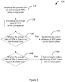
- Fig. 3 is a flowchart showing a method of monitoring the APU turbine efficiency according to an embodiment not covered by the claims of the present invention.
- Step 410 of the method 400 of monitoring the APU turbine efficiency is to obtain the data of the status of the aircraft APU startup within a period, which comprises at least the rotation speed at the peak of EGT.
- the information required at Step 410 can be obtained from, for example, the APU message i.e. A13 message.
- the A13 message for the aircraft APU operation can be obtained in real time from the control center of the Society of International Telecommunications Aeronautics (SITA) or the control center of the Aviation Data Communication Corporation (ADCC) of China.
- the required information of the status of the aircraft APU startup can be obtained by decoding the A13 message showing the operation status of the aircraft APU by a message decoder.
- Step 430 is to judge whether the average of the NPA during the period is close to a first threshold, and if the average of the NPA has been close to the first threshold, the APU turbine efficiency is determined to enter the decline phase at Step 440.
- Step 450 is to judge whether the average of the NPA during the period is close to a second threshold, and if the average of the NPA has been close to the second threshold, the APU turbine efficiency is determined to enter the failure phase at Step 460.
- the average of the NPA becomes better and better.
- This can be referred to as a moving window method in which the trend is analyzed by using continuously updated data in a certain period.
- the size of the moving window namely the number M of the points included in the calculation, depends on a number of factors, such as time interval between different measurements and control strategy and so forth. The smaller the moving window is, the easier the volatility of data will be affected by normal fluctuation, and thus various misinformation will occur, which will affect the technical effect of the present invention. If the moving window is overlarge, although the trend of changes will be reflected more accurately, the timeliness of the present invention will be reduced and warning information cannot be delivered timely.
- the size of the moving window plays an important role in the present invention.
- the value of M is around 20 on the condition that 2 to 3 points are measured in each day.
- the value of M is around 10 on the condition that the number of points measured in each day is less than or equals to 2.
- the information required at Step 510 can be obtained from, for example, the APU message of the A13 message.
- the A13 message for the aircraft APU operation can be obtained in real time from the control center of the Society of International Telecommunications Aeronautics (SITA) or the control center of the Aviation Data Communication Corporation (ADCC) of China.
- the required information of the status of the aircraft APU startup can be obtained by decoding the A13 message showing the operation status of the aircraft APU by a message decoder.
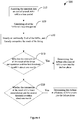
- Step 520 is to calculate all of the NPAs during the period according to the obtained rotation speed at the peak of EGT and the constant APU rotation speed.
- Step 530 is to linearly or nonlinearly fit all of the NPAs in the period, and to linearly extrapolate the result of the fitting.
- Step 540 is to determine that the APU turbine efficiency enters the decline phase if the intersection of the result of the linear extrapolation and the first threshold is within about one month.
- Step 550 is to determine that the APU turbine efficiency enters the failure phase if the intersection of the result of the linear extrapolation and the second threshold is within about one month.
- the confidence interval of the NPA is calculated after the linear or nonlinear fitting. According to the intersections of the result of the extrapolation of the confidence interval and the first and second thresholds, the time range in which the APU efficiency enters the decline or failure phase is estimated.
- other APU startup parameters such as the exhausting gas temperature peak EGTP at the APU's startup, also can be used to assist in judging whether the APU turbine efficiency enters the decline phase.
- the exhausting gas temperature peak EGTP at the APU's startup may be close to its red line value, namely, the maximum exhausting gas temperature allowable to the APU's operation.
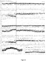
- Fig. 5 shows an example of the change of the APU turbine efficiency according to an example of the present invention, in which the APU turbine efficiency is replaced at the solid line.
- the NPA decreases gradually to be close to and then exceed the first threshold 43%, and then the NPA is approaching the second threshold 40%.
- an alarm will be generated soon, which alarm that the APU turbine efficiency deteriorates and enters into the decline or failure phase.
- the startup time STA remains normal.
- the EGTA approaches the red line value 840 degree, and the corrected EGTA_cor also approaches its red line value 900 degree.
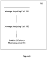
- Fig. 6 is a block diagram illustrating a device for monitoring the APU turbine efficiency of an aircraft according to an embodiment of the present invention.
- the device for monitoring an APU turbine efficiency comprises: a message obtaining unit 701 for obtaining APU messages within a period; a message parsing unit 702 for parsing out required operation data relating to the APU turbine efficiency; and a turbine efficiency monitoring unit 703 for determining the performance of the APU turbine efficiency is in a stable, decline or failure phase according to the operation data relating to the turbine efficiency.
- a device for monitoring performance of an APU turbine efficiency of an aircraft comprises: a processor; and a storage connecting with the processor for storing a computer-readable code, wherein the computer-readable code is run on the processor to implement the steps of: obtaining APU messages within a period; parsing out operation data relating to the APU turbine efficiency based on the messages, the operation data including NPA; and determining the performance of the APU turbine efficiency is in a stable, decline or failure phase.
Landscapes
- Engineering & Computer Science (AREA)
- Chemical & Material Sciences (AREA)
- Combustion & Propulsion (AREA)
- Mechanical Engineering (AREA)
- General Engineering & Computer Science (AREA)
- Physics & Mathematics (AREA)
- General Physics & Mathematics (AREA)
- Control Of Turbines (AREA)
Applications Claiming Priority (1)
| Application Number | Priority Date | Filing Date | Title |
|---|---|---|---|
| CN201310313879.0A CN104343476B (zh) | 2013-07-24 | 2013-07-24 | 飞机辅助动力单元涡轮效率监控方法和装置 |
Publications (2)
| Publication Number | Publication Date |
|---|---|
| EP2829686A1 EP2829686A1 (en) | 2015-01-28 |
| EP2829686B1 true EP2829686B1 (en) | 2017-06-14 |
Family
ID=51224788
Family Applications (1)
| Application Number | Title | Priority Date | Filing Date |
|---|---|---|---|
| EP14178430.6A Active EP2829686B1 (en) | 2013-07-24 | 2014-07-24 | Method and apparatus for monitoring turbine efficiency of an aircraft auxiliary power unit |
Country Status (9)
| Country | Link |
|---|---|
| US (1) | US9696239B2 (enExample) |
| EP (1) | EP2829686B1 (enExample) |
| JP (1) | JP6205319B2 (enExample) |
| KR (1) | KR101998187B1 (enExample) |
| CN (1) | CN104343476B (enExample) |
| AU (1) | AU2014206182B2 (enExample) |
| CA (1) | CA2857787C (enExample) |
| SG (1) | SG10201404368YA (enExample) |
| TW (1) | TWI625271B (enExample) |
Families Citing this family (8)
| Publication number | Priority date | Publication date | Assignee | Title |
|---|---|---|---|---|
| WO2014005070A1 (en) * | 2012-06-28 | 2014-01-03 | Alaska Airlines, Inc. | Robust systems and methods for improving passenger jet aircraft fuel economy |
| CN105114977B (zh) * | 2015-09-02 | 2017-05-24 | 哈尔滨工业大学 | 一种基于排温测点相关性的燃机燃烧系统在线监测方法 |
| CN110341986B (zh) * | 2019-07-16 | 2021-07-20 | 哈尔滨工业大学 | 基于rbm优化elm的飞机辅助动力装置性能参数多步预测方法 |
| CN111693180B (zh) * | 2020-05-27 | 2021-07-23 | 中国航空工业集团公司西安航空计算技术研究所 | 一种辅助动力系统排气温度超温故障检测方法 |
| CN115356027B (zh) * | 2022-08-15 | 2026-03-24 | 中国航发沈阳发动机研究所 | 一种基于低压轴功率平衡的高压涡轮效率评估方法及装置 |
| CN115598499A (zh) * | 2022-10-13 | 2023-01-13 | 珠海格力电器股份有限公司(Cn) | 故障隐患的检测方法和装置、控制器的保护设备 |
| CN119429157B (zh) * | 2024-11-13 | 2025-11-25 | 中国南方航空股份有限公司 | 一种航空滑油冷却器的维护方法、系统、设备和介质 |
| CN120793187B (zh) * | 2025-09-02 | 2025-11-11 | 商飞软件有限公司 | 一种民用辅助动力装置转速综合控制方法 |
Family Cites Families (10)
| Publication number | Priority date | Publication date | Assignee | Title |
|---|---|---|---|---|
| US6466858B1 (en) * | 2000-11-02 | 2002-10-15 | General Electric Company | Methods and apparatus for monitoring gas turbine engine operation |
| US6470258B1 (en) * | 2001-05-18 | 2002-10-22 | General Electric Company | System and method for monitoring engine starting systems |
| US7487029B2 (en) * | 2004-05-21 | 2009-02-03 | Pratt & Whitney Canada | Method of monitoring gas turbine engine operation |
| US7506517B2 (en) | 2004-11-23 | 2009-03-24 | Honeywell International, Inc. | System and method for turbine engine startup profile characterization |
| US7369932B2 (en) | 2006-05-04 | 2008-05-06 | Honeywell International, Inc. | System and method for turbine engine fault detection using discrete event system modeling |
| US8467949B2 (en) | 2009-05-29 | 2013-06-18 | Honeywell International Inc. | Methods and systems for turbine line replaceable unit fault detection and isolation during engine startup |
| CN102095572A (zh) * | 2010-12-06 | 2011-06-15 | 广州市熠芯节能服务有限公司 | 基于标杆产品比对的产品性能测试方法 |
| CN102343983A (zh) * | 2011-07-07 | 2012-02-08 | 中国国际航空股份有限公司 | 飞机apu性能检测方法 |
| CN102320382A (zh) | 2011-07-07 | 2012-01-18 | 中国国际航空股份有限公司 | 飞机性能检测方法 |
| CN102416821A (zh) * | 2011-07-27 | 2012-04-18 | 中国国际航空股份有限公司 | 飞机系统数据处理方法 |
-
2013
- 2013-07-24 CN CN201310313879.0A patent/CN104343476B/zh active Active
-
2014
- 2014-07-23 US US14/338,553 patent/US9696239B2/en active Active
- 2014-07-24 AU AU2014206182A patent/AU2014206182B2/en active Active
- 2014-07-24 KR KR1020140093938A patent/KR101998187B1/ko active Active
- 2014-07-24 TW TW103125396A patent/TWI625271B/zh active
- 2014-07-24 EP EP14178430.6A patent/EP2829686B1/en active Active
- 2014-07-24 SG SG10201404368YA patent/SG10201404368YA/en unknown
- 2014-07-24 JP JP2014151067A patent/JP6205319B2/ja active Active
- 2014-07-24 CA CA2857787A patent/CA2857787C/en active Active
Also Published As
| Publication number | Publication date |
|---|---|
| CN104343476A (zh) | 2015-02-11 |
| JP6205319B2 (ja) | 2017-09-27 |
| US20160195455A1 (en) | 2016-07-07 |
| AU2014206182B2 (en) | 2017-12-21 |
| JP2015025451A (ja) | 2015-02-05 |
| HK1202322A1 (zh) | 2015-09-25 |
| CA2857787A1 (en) | 2015-01-24 |
| AU2014206182A1 (en) | 2015-02-12 |
| EP2829686A1 (en) | 2015-01-28 |
| KR20150012216A (ko) | 2015-02-03 |
| TWI625271B (zh) | 2018-06-01 |
| TW201518174A (zh) | 2015-05-16 |
| KR101998187B1 (ko) | 2019-07-09 |
| CA2857787C (en) | 2019-04-16 |
| US9696239B2 (en) | 2017-07-04 |
| CN104343476B (zh) | 2016-06-08 |
| SG10201404368YA (en) | 2015-02-27 |
Similar Documents
| Publication | Publication Date | Title |
|---|---|---|
| EP2829686B1 (en) | Method and apparatus for monitoring turbine efficiency of an aircraft auxiliary power unit | |
| EP2829721B1 (en) | Method and apparatus for detecting performance of an APU starter | |
| TWI460100B (zh) | 一種檢測飛機部件的性能進入衰退期的方法、其檢測參數的檢測方法及其飛機維修方法 | |
| EP2543852B1 (en) | Method for assessing the performance of auxiliary power unit | |
| US9657649B2 (en) | Method and apparatus for detecting performance of an APU fuel assembly | |
| EP2829688A1 (en) | Method and device for monitoring an APU turbine | |
| HK1202322B (en) | Method and apparatus for monitoring turbine efficiency of aircraft auxiliary power unit | |
| HK1202348B (en) | Method and apparatus for detecting performance of an apu fuel assembly | |
| HK1202100A1 (en) | Method and apparatus for monitoring performance of the lubricant cooler in aircraft auxiliary power unit | |
| HK1179584B (en) | Method for detecting whether performance of aircraft component is in the deterioration period and method for maintenance of aircraft | |
| HK1202100B (en) | Method and apparatus for monitoring performance of the lubricant cooler in aircraft auxiliary power unit | |
| HK1202337B (en) | Method and apparatus for detecting performance of an apu starter |
Legal Events
| Date | Code | Title | Description |
|---|---|---|---|
| 17P | Request for examination filed |
Effective date: 20140724 |
|
| AK | Designated contracting states |
Kind code of ref document: A1 Designated state(s): AL AT BE BG CH CY CZ DE DK EE ES FI FR GB GR HR HU IE IS IT LI LT LU LV MC MK MT NL NO PL PT RO RS SE SI SK SM TR |
|
| AX | Request for extension of the european patent |
Extension state: BA ME |
|
| PUAI | Public reference made under article 153(3) epc to a published international application that has entered the european phase |
Free format text: ORIGINAL CODE: 0009012 |
|
| R17P | Request for examination filed (corrected) |
Effective date: 20150708 |
|
| RBV | Designated contracting states (corrected) |
Designated state(s): AL AT BE BG CH CY CZ DE DK EE ES FI FR GB GR HR HU IE IS IT LI LT LU LV MC MK MT NL NO PL PT RO RS SE SI SK SM TR |
|
| 17Q | First examination report despatched |
Effective date: 20160127 |
|
| REG | Reference to a national code |
Ref country code: DE Ref legal event code: R079 Ref document number: 602014010677 Country of ref document: DE Free format text: PREVIOUS MAIN CLASS: F01D0019000000 Ipc: F02C0007260000 |
|
| GRAP | Despatch of communication of intention to grant a patent |
Free format text: ORIGINAL CODE: EPIDOSNIGR1 |
|
| RIC1 | Information provided on ipc code assigned before grant |
Ipc: F02C 7/26 20060101AFI20170111BHEP Ipc: F02C 9/00 20060101ALI20170111BHEP |
|
| INTG | Intention to grant announced |
Effective date: 20170207 |
|
| GRAS | Grant fee paid |
Free format text: ORIGINAL CODE: EPIDOSNIGR3 |
|
| GRAA | (expected) grant |
Free format text: ORIGINAL CODE: 0009210 |
|
| AK | Designated contracting states |
Kind code of ref document: B1 Designated state(s): AL AT BE BG CH CY CZ DE DK EE ES FI FR GB GR HR HU IE IS IT LI LT LU LV MC MK MT NL NO PL PT RO RS SE SI SK SM TR |
|
| REG | Reference to a national code |
Ref country code: GB Ref legal event code: FG4D |
|
| REG | Reference to a national code |
Ref country code: CH Ref legal event code: EP Ref country code: AT Ref legal event code: REF Ref document number: 901204 Country of ref document: AT Kind code of ref document: T Effective date: 20170615 |
|
| REG | Reference to a national code |
Ref country code: IE Ref legal event code: FG4D |
|
| REG | Reference to a national code |
Ref country code: DE Ref legal event code: R096 Ref document number: 602014010677 Country of ref document: DE |
|
| REG | Reference to a national code |
Ref country code: FR Ref legal event code: PLFP Year of fee payment: 4 |
|
| REG | Reference to a national code |
Ref country code: NL Ref legal event code: MP Effective date: 20170614 |
|
| REG | Reference to a national code |
Ref country code: LT Ref legal event code: MG4D |
|
| PG25 | Lapsed in a contracting state [announced via postgrant information from national office to epo] |
Ref country code: HR Free format text: LAPSE BECAUSE OF FAILURE TO SUBMIT A TRANSLATION OF THE DESCRIPTION OR TO PAY THE FEE WITHIN THE PRESCRIBED TIME-LIMIT Effective date: 20170614 Ref country code: LT Free format text: LAPSE BECAUSE OF FAILURE TO SUBMIT A TRANSLATION OF THE DESCRIPTION OR TO PAY THE FEE WITHIN THE PRESCRIBED TIME-LIMIT Effective date: 20170614 Ref country code: NO Free format text: LAPSE BECAUSE OF FAILURE TO SUBMIT A TRANSLATION OF THE DESCRIPTION OR TO PAY THE FEE WITHIN THE PRESCRIBED TIME-LIMIT Effective date: 20170914 Ref country code: GR Free format text: LAPSE BECAUSE OF FAILURE TO SUBMIT A TRANSLATION OF THE DESCRIPTION OR TO PAY THE FEE WITHIN THE PRESCRIBED TIME-LIMIT Effective date: 20170915 Ref country code: FI Free format text: LAPSE BECAUSE OF FAILURE TO SUBMIT A TRANSLATION OF THE DESCRIPTION OR TO PAY THE FEE WITHIN THE PRESCRIBED TIME-LIMIT Effective date: 20170614 |
|
| REG | Reference to a national code |
Ref country code: AT Ref legal event code: MK05 Ref document number: 901204 Country of ref document: AT Kind code of ref document: T Effective date: 20170614 |
|
| PG25 | Lapsed in a contracting state [announced via postgrant information from national office to epo] |
Ref country code: NL Free format text: LAPSE BECAUSE OF FAILURE TO SUBMIT A TRANSLATION OF THE DESCRIPTION OR TO PAY THE FEE WITHIN THE PRESCRIBED TIME-LIMIT Effective date: 20170614 Ref country code: RS Free format text: LAPSE BECAUSE OF FAILURE TO SUBMIT A TRANSLATION OF THE DESCRIPTION OR TO PAY THE FEE WITHIN THE PRESCRIBED TIME-LIMIT Effective date: 20170614 Ref country code: LV Free format text: LAPSE BECAUSE OF FAILURE TO SUBMIT A TRANSLATION OF THE DESCRIPTION OR TO PAY THE FEE WITHIN THE PRESCRIBED TIME-LIMIT Effective date: 20170614 Ref country code: SE Free format text: LAPSE BECAUSE OF FAILURE TO SUBMIT A TRANSLATION OF THE DESCRIPTION OR TO PAY THE FEE WITHIN THE PRESCRIBED TIME-LIMIT Effective date: 20170614 Ref country code: BG Free format text: LAPSE BECAUSE OF FAILURE TO SUBMIT A TRANSLATION OF THE DESCRIPTION OR TO PAY THE FEE WITHIN THE PRESCRIBED TIME-LIMIT Effective date: 20170914 |
|
| PG25 | Lapsed in a contracting state [announced via postgrant information from national office to epo] |
Ref country code: EE Free format text: LAPSE BECAUSE OF FAILURE TO SUBMIT A TRANSLATION OF THE DESCRIPTION OR TO PAY THE FEE WITHIN THE PRESCRIBED TIME-LIMIT Effective date: 20170614 Ref country code: RO Free format text: LAPSE BECAUSE OF FAILURE TO SUBMIT A TRANSLATION OF THE DESCRIPTION OR TO PAY THE FEE WITHIN THE PRESCRIBED TIME-LIMIT Effective date: 20170614 Ref country code: AT Free format text: LAPSE BECAUSE OF FAILURE TO SUBMIT A TRANSLATION OF THE DESCRIPTION OR TO PAY THE FEE WITHIN THE PRESCRIBED TIME-LIMIT Effective date: 20170614 Ref country code: SK Free format text: LAPSE BECAUSE OF FAILURE TO SUBMIT A TRANSLATION OF THE DESCRIPTION OR TO PAY THE FEE WITHIN THE PRESCRIBED TIME-LIMIT Effective date: 20170614 Ref country code: CZ Free format text: LAPSE BECAUSE OF FAILURE TO SUBMIT A TRANSLATION OF THE DESCRIPTION OR TO PAY THE FEE WITHIN THE PRESCRIBED TIME-LIMIT Effective date: 20170614 |
|
| PG25 | Lapsed in a contracting state [announced via postgrant information from national office to epo] |
Ref country code: PL Free format text: LAPSE BECAUSE OF FAILURE TO SUBMIT A TRANSLATION OF THE DESCRIPTION OR TO PAY THE FEE WITHIN THE PRESCRIBED TIME-LIMIT Effective date: 20170614 Ref country code: SM Free format text: LAPSE BECAUSE OF FAILURE TO SUBMIT A TRANSLATION OF THE DESCRIPTION OR TO PAY THE FEE WITHIN THE PRESCRIBED TIME-LIMIT Effective date: 20170614 Ref country code: IS Free format text: LAPSE BECAUSE OF FAILURE TO SUBMIT A TRANSLATION OF THE DESCRIPTION OR TO PAY THE FEE WITHIN THE PRESCRIBED TIME-LIMIT Effective date: 20171014 Ref country code: ES Free format text: LAPSE BECAUSE OF FAILURE TO SUBMIT A TRANSLATION OF THE DESCRIPTION OR TO PAY THE FEE WITHIN THE PRESCRIBED TIME-LIMIT Effective date: 20170614 Ref country code: IT Free format text: LAPSE BECAUSE OF FAILURE TO SUBMIT A TRANSLATION OF THE DESCRIPTION OR TO PAY THE FEE WITHIN THE PRESCRIBED TIME-LIMIT Effective date: 20170614 |
|
| REG | Reference to a national code |
Ref country code: CH Ref legal event code: PL |
|
| REG | Reference to a national code |
Ref country code: DE Ref legal event code: R097 Ref document number: 602014010677 Country of ref document: DE |
|
| PG25 | Lapsed in a contracting state [announced via postgrant information from national office to epo] |
Ref country code: MC Free format text: LAPSE BECAUSE OF FAILURE TO SUBMIT A TRANSLATION OF THE DESCRIPTION OR TO PAY THE FEE WITHIN THE PRESCRIBED TIME-LIMIT Effective date: 20170614 |
|
| REG | Reference to a national code |
Ref country code: IE Ref legal event code: MM4A |
|
| PLBE | No opposition filed within time limit |
Free format text: ORIGINAL CODE: 0009261 |
|
| STAA | Information on the status of an ep patent application or granted ep patent |
Free format text: STATUS: NO OPPOSITION FILED WITHIN TIME LIMIT |
|
| PG25 | Lapsed in a contracting state [announced via postgrant information from national office to epo] |
Ref country code: LI Free format text: LAPSE BECAUSE OF NON-PAYMENT OF DUE FEES Effective date: 20170731 Ref country code: IE Free format text: LAPSE BECAUSE OF NON-PAYMENT OF DUE FEES Effective date: 20170724 Ref country code: DK Free format text: LAPSE BECAUSE OF FAILURE TO SUBMIT A TRANSLATION OF THE DESCRIPTION OR TO PAY THE FEE WITHIN THE PRESCRIBED TIME-LIMIT Effective date: 20170614 Ref country code: CH Free format text: LAPSE BECAUSE OF NON-PAYMENT OF DUE FEES Effective date: 20170731 |
|
| REG | Reference to a national code |
Ref country code: BE Ref legal event code: MM Effective date: 20170731 |
|
| 26N | No opposition filed |
Effective date: 20180315 |
|
| PG25 | Lapsed in a contracting state [announced via postgrant information from national office to epo] |
Ref country code: LU Free format text: LAPSE BECAUSE OF NON-PAYMENT OF DUE FEES Effective date: 20170724 |
|
| REG | Reference to a national code |
Ref country code: FR Ref legal event code: PLFP Year of fee payment: 5 |
|
| PG25 | Lapsed in a contracting state [announced via postgrant information from national office to epo] |
Ref country code: SI Free format text: LAPSE BECAUSE OF FAILURE TO SUBMIT A TRANSLATION OF THE DESCRIPTION OR TO PAY THE FEE WITHIN THE PRESCRIBED TIME-LIMIT Effective date: 20170614 Ref country code: BE Free format text: LAPSE BECAUSE OF NON-PAYMENT OF DUE FEES Effective date: 20170731 |
|
| PG25 | Lapsed in a contracting state [announced via postgrant information from national office to epo] |
Ref country code: MT Free format text: LAPSE BECAUSE OF NON-PAYMENT OF DUE FEES Effective date: 20170724 |
|
| PG25 | Lapsed in a contracting state [announced via postgrant information from national office to epo] |
Ref country code: HU Free format text: LAPSE BECAUSE OF FAILURE TO SUBMIT A TRANSLATION OF THE DESCRIPTION OR TO PAY THE FEE WITHIN THE PRESCRIBED TIME-LIMIT; INVALID AB INITIO Effective date: 20140724 |
|
| PG25 | Lapsed in a contracting state [announced via postgrant information from national office to epo] |
Ref country code: CY Free format text: LAPSE BECAUSE OF FAILURE TO SUBMIT A TRANSLATION OF THE DESCRIPTION OR TO PAY THE FEE WITHIN THE PRESCRIBED TIME-LIMIT Effective date: 20170614 |
|
| PG25 | Lapsed in a contracting state [announced via postgrant information from national office to epo] |
Ref country code: MK Free format text: LAPSE BECAUSE OF FAILURE TO SUBMIT A TRANSLATION OF THE DESCRIPTION OR TO PAY THE FEE WITHIN THE PRESCRIBED TIME-LIMIT Effective date: 20170614 |
|
| PG25 | Lapsed in a contracting state [announced via postgrant information from national office to epo] |
Ref country code: TR Free format text: LAPSE BECAUSE OF FAILURE TO SUBMIT A TRANSLATION OF THE DESCRIPTION OR TO PAY THE FEE WITHIN THE PRESCRIBED TIME-LIMIT Effective date: 20170614 |
|
| PG25 | Lapsed in a contracting state [announced via postgrant information from national office to epo] |
Ref country code: PT Free format text: LAPSE BECAUSE OF FAILURE TO SUBMIT A TRANSLATION OF THE DESCRIPTION OR TO PAY THE FEE WITHIN THE PRESCRIBED TIME-LIMIT Effective date: 20170614 |
|
| PG25 | Lapsed in a contracting state [announced via postgrant information from national office to epo] |
Ref country code: AL Free format text: LAPSE BECAUSE OF FAILURE TO SUBMIT A TRANSLATION OF THE DESCRIPTION OR TO PAY THE FEE WITHIN THE PRESCRIBED TIME-LIMIT Effective date: 20170614 |
|
| PGFP | Annual fee paid to national office [announced via postgrant information from national office to epo] |
Ref country code: DE Payment date: 20250724 Year of fee payment: 12 |
|
| PGFP | Annual fee paid to national office [announced via postgrant information from national office to epo] |
Ref country code: GB Payment date: 20250723 Year of fee payment: 12 |
|
| PGFP | Annual fee paid to national office [announced via postgrant information from national office to epo] |
Ref country code: FR Payment date: 20250728 Year of fee payment: 12 |