EP2829721B1 - Method and apparatus for detecting performance of an APU starter - Google Patents
Method and apparatus for detecting performance of an APU starter Download PDFInfo
- Publication number
- EP2829721B1 EP2829721B1 EP14178339.9A EP14178339A EP2829721B1 EP 2829721 B1 EP2829721 B1 EP 2829721B1 EP 14178339 A EP14178339 A EP 14178339A EP 2829721 B1 EP2829721 B1 EP 2829721B1
- Authority
- EP
- European Patent Office
- Prior art keywords
- apu
- starter
- phase
- performance
- decline
- Prior art date
- Legal status (The legal status is an assumption and is not a legal conclusion. Google has not performed a legal analysis and makes no representation as to the accuracy of the status listed.)
- Active
Links
- 239000007858 starting material Substances 0.000 title claims description 111
- 238000000034 method Methods 0.000 title claims description 35
- 230000007423 decrease Effects 0.000 claims description 62
- 238000001514 detection method Methods 0.000 claims description 10
- 239000000446 fuel Substances 0.000 claims description 10
- 238000012423 maintenance Methods 0.000 description 7
- 230000007257 malfunction Effects 0.000 description 6
- 230000006866 deterioration Effects 0.000 description 4
- 238000004891 communication Methods 0.000 description 3
- 238000011217 control strategy Methods 0.000 description 3
- 238000012544 monitoring process Methods 0.000 description 3
- 239000000243 solution Substances 0.000 description 3
- XEEYBQQBJWHFJM-UHFFFAOYSA-N Iron Chemical compound [Fe] XEEYBQQBJWHFJM-UHFFFAOYSA-N 0.000 description 2
- 238000004378 air conditioning Methods 0.000 description 2
- 230000015556 catabolic process Effects 0.000 description 2
- 238000010586 diagram Methods 0.000 description 2
- 239000006185 dispersion Substances 0.000 description 2
- 230000000694 effects Effects 0.000 description 2
- 230000003068 static effect Effects 0.000 description 2
- OKTJSMMVPCPJKN-UHFFFAOYSA-N Carbon Chemical compound [C] OKTJSMMVPCPJKN-UHFFFAOYSA-N 0.000 description 1
- RYGMFSIKBFXOCR-UHFFFAOYSA-N Copper Chemical compound [Cu] RYGMFSIKBFXOCR-UHFFFAOYSA-N 0.000 description 1
- 230000002159 abnormal effect Effects 0.000 description 1
- 239000000654 additive Substances 0.000 description 1
- 230000000996 additive effect Effects 0.000 description 1
- 230000002411 adverse Effects 0.000 description 1
- 229910052799 carbon Inorganic materials 0.000 description 1
- 238000002485 combustion reaction Methods 0.000 description 1
- 229910052802 copper Inorganic materials 0.000 description 1
- 239000010949 copper Substances 0.000 description 1
- 125000004122 cyclic group Chemical group 0.000 description 1
- 230000001419 dependent effect Effects 0.000 description 1
- 238000005516 engineering process Methods 0.000 description 1
- 238000002347 injection Methods 0.000 description 1
- 239000007924 injection Substances 0.000 description 1
- 238000007689 inspection Methods 0.000 description 1
- 229910052742 iron Inorganic materials 0.000 description 1
- 230000009191 jumping Effects 0.000 description 1
- 238000005259 measurement Methods 0.000 description 1
- 238000012545 processing Methods 0.000 description 1
- 238000011897 real-time detection Methods 0.000 description 1
- 239000013074 reference sample Substances 0.000 description 1
- 230000001105 regulatory effect Effects 0.000 description 1
- 230000000717 retained effect Effects 0.000 description 1
- 239000000523 sample Substances 0.000 description 1
Images


Classifications
-
- F—MECHANICAL ENGINEERING; LIGHTING; HEATING; WEAPONS; BLASTING
- F02—COMBUSTION ENGINES; HOT-GAS OR COMBUSTION-PRODUCT ENGINE PLANTS
- F02N—STARTING OF COMBUSTION ENGINES; STARTING AIDS FOR SUCH ENGINES, NOT OTHERWISE PROVIDED FOR
- F02N11/00—Starting of engines by means of electric motors
- F02N11/10—Safety devices
- F02N11/108—Safety devices for diagnosis of the starter or its components
-
- B—PERFORMING OPERATIONS; TRANSPORTING
- B64—AIRCRAFT; AVIATION; COSMONAUTICS
- B64D—EQUIPMENT FOR FITTING IN OR TO AIRCRAFT; FLIGHT SUITS; PARACHUTES; ARRANGEMENTS OR MOUNTING OF POWER PLANTS OR PROPULSION TRANSMISSIONS IN AIRCRAFT
- B64D41/00—Power installations for auxiliary purposes
-
- G—PHYSICS
- G05—CONTROLLING; REGULATING
- G05B—CONTROL OR REGULATING SYSTEMS IN GENERAL; FUNCTIONAL ELEMENTS OF SUCH SYSTEMS; MONITORING OR TESTING ARRANGEMENTS FOR SUCH SYSTEMS OR ELEMENTS
- G05B23/00—Testing or monitoring of control systems or parts thereof
- G05B23/02—Electric testing or monitoring
- G05B23/0205—Electric testing or monitoring by means of a monitoring system capable of detecting and responding to faults
- G05B23/0218—Electric testing or monitoring by means of a monitoring system capable of detecting and responding to faults characterised by the fault detection method dealing with either existing or incipient faults
- G05B23/0224—Process history based detection method, e.g. whereby history implies the availability of large amounts of data
- G05B23/0227—Qualitative history assessment, whereby the type of data acted upon, e.g. waveforms, images or patterns, is not relevant, e.g. rule based assessment; if-then decisions
- G05B23/0235—Qualitative history assessment, whereby the type of data acted upon, e.g. waveforms, images or patterns, is not relevant, e.g. rule based assessment; if-then decisions based on a comparison with predetermined threshold or range, e.g. "classical methods", carried out during normal operation; threshold adaptation or choice; when or how to compare with the threshold
-
- G—PHYSICS
- G07—CHECKING-DEVICES
- G07C—TIME OR ATTENDANCE REGISTERS; REGISTERING OR INDICATING THE WORKING OF MACHINES; GENERATING RANDOM NUMBERS; VOTING OR LOTTERY APPARATUS; ARRANGEMENTS, SYSTEMS OR APPARATUS FOR CHECKING NOT PROVIDED FOR ELSEWHERE
- G07C5/00—Registering or indicating the working of vehicles
- G07C5/08—Registering or indicating performance data other than driving, working, idle, or waiting time, with or without registering driving, working, idle or waiting time
- G07C5/0808—Diagnosing performance data
-
- G—PHYSICS
- G07—CHECKING-DEVICES
- G07C—TIME OR ATTENDANCE REGISTERS; REGISTERING OR INDICATING THE WORKING OF MACHINES; GENERATING RANDOM NUMBERS; VOTING OR LOTTERY APPARATUS; ARRANGEMENTS, SYSTEMS OR APPARATUS FOR CHECKING NOT PROVIDED FOR ELSEWHERE
- G07C5/00—Registering or indicating the working of vehicles
- G07C5/08—Registering or indicating performance data other than driving, working, idle, or waiting time, with or without registering driving, working, idle or waiting time
- G07C5/0816—Indicating performance data, e.g. occurrence of a malfunction
-
- F—MECHANICAL ENGINEERING; LIGHTING; HEATING; WEAPONS; BLASTING
- F05—INDEXING SCHEMES RELATING TO ENGINES OR PUMPS IN VARIOUS SUBCLASSES OF CLASSES F01-F04
- F05D—INDEXING SCHEME FOR ASPECTS RELATING TO NON-POSITIVE-DISPLACEMENT MACHINES OR ENGINES, GAS-TURBINES OR JET-PROPULSION PLANTS
- F05D2220/00—Application
- F05D2220/50—Application for auxiliary power units (APU's)
-
- F—MECHANICAL ENGINEERING; LIGHTING; HEATING; WEAPONS; BLASTING
- F05—INDEXING SCHEMES RELATING TO ENGINES OR PUMPS IN VARIOUS SUBCLASSES OF CLASSES F01-F04
- F05D—INDEXING SCHEME FOR ASPECTS RELATING TO NON-POSITIVE-DISPLACEMENT MACHINES OR ENGINES, GAS-TURBINES OR JET-PROPULSION PLANTS
- F05D2260/00—Function
- F05D2260/80—Diagnostics
Definitions
- the present invention relates to a method and an apparatus for detecting performance of the starter of an aircraft auxiliary power unit.
- EP 2 543 852 A2 describes a method for detecting the performance of an auxiliary power unit (APU) of an aircraft.
- a plurality of running parameters of the APU is obtained. Those parameters are compared with respective threshold values. Weights are assigned to the comparison results and the performance of the APU is evaluated based on the weighted comparison results.
- US 2003/0149550 A1 discloses a system monitoring the performance of aircrafts and generating a warning message when an abnormal situation is detected.
- the system is operated to manage an entire fleet of aircraft. Data from sensors of each aircraft is sent to a central processing station, where the data is stored in a central database. Incoming data from an aircraft is monitored over a specific number of samples (window). The window is continually monitored to search for alert conditions based on normalized thresholds for specific parameters.
- An Airborne Auxiliary Power Unit abbreviated as APU, is a small turbine engine mounted on the tail of an aircraft. Its main function is to supply power and gas sources, with a few APUs capable of providing additive thrust to the aircraft.
- an aircraft may do not need to rely on ground power and gas source vehicles to start the aircraft as its main engine may be started via power supply from the APU. While on the ground, the APU also supplies power and compressed air to ensure lighting and air-conditioning in the cabin and cockpit. During take-off of an aircraft, the APU can serve as a backup power source. After the aircraft is landed, lighting and air-conditioning of the aircraft are still powered by the APU. The functions of APU determine that its stability directly affects flight cost and quality of service of the aircraft.
- Ignition of APU is realized via a starter.
- the structure and cyclic process of the aircraft gas turbine engine decides that it cannot be ignited autonomously. This is because that, if fuel injection and ignition is performed directly in a static engine, the air compressor does not rotate so as to provide pressure to the air and the gas could not move backward to rotate the turbine, in which way the combustion chamber and turbine guide vane will be burnt out. Therefore, the feature for starting the gas turbine engine is: the air flows at first, and then ignition occurs, namely, the engine needs to be rotated firstly and then be started. According to the above feature, before ignition, the engine must be rotated via the starter by consuming electric power.
- the starting of an APU is the process of accelerating the APU rotator from a static state to a stable working state, namely, the working process for the APU rotator to accelerate its rotation speed from 0 to over 95%.
- the APU rotator may reach a required working rotation speed within a prescribed time and enters into a stable working state mainly depends on the torque the APU rotator obtains during the starting process.
- As the service time of the starter increases its efficiency reduces gradually due to the decrease of contact of the carbon brush or increase of internal friction caused by internal field deformation, increasing loss of copper and iron, mechanical wear and the like, and the output power reduces accordingly.
- the starter cannot provide the APU rotator with an adequate torque, namely failure of the starter occurs.
- APU starter is an important component of APU. Once the starter fails, it will directly cause the APU unable to start, and thus cause the aircraft unable to fly. According to statistics, failure of starter occupies nearly half of the total amount malfunctions of APU, and is a main cause affecting normal operation of APU. It is also a main problem that needs to be solved so as to improve maintenance of APU. Currently, there is not any effective way to maintain the APU starter except for breakdown maintenance.
- a method for detecting an APU starter comprises: obtaining APU-related messages at multiple time points within a time period; obtaining running parameters of the APU starter according to the messages, the running parameters comprising starting time STA; calculating average value AVG and deviation index ⁇ of the starting time STA within said time period, wherein the deviation index ⁇ is the standard deviation; determining whether performance of the APU starter is in a stable phase, decline phase or failure phase according to the deviation index ⁇ .
- the step for determining whether performance of the APU starter is in a stable phase, decline phase or failure phase comprises: in response to that the deviation index ⁇ is smaller than the decline threshold value, determining that performance of the APU starter is in a stable phase; in response to that the deviation index ⁇ is larger than the decline threshold value and smaller than the failure threshold value, determining that performance of the APU starter is in a decline phase; and in response to that the deviation index ⁇ is larger than the failure threshold value, determining that performance of the APU starter is in a failure phase.
- the method may further comprise determining the deviation index ⁇ when performance of the APU starter is in a stable phase, wherein the decline threshold value is around 1.5 to 2.0 times of the stable deviation index ⁇ , and the failure threshold value is around 2 to 3 times of the stable deviation index ⁇ .
- the time period may be about 2 to 3 days.
- About 5 to 10 APU-related messages may be obtained within said time period.
- the method may further comprise: determining starting time STA next obtained according to a next APU-related message; in response to that STA next is larger than AVG+n ⁇ , determining whether STA next+1 obtained according to a next APU-related message is larger than AVG+n ⁇ ; and in response to that the number of times for starting time STA obtained according to APU-related message continuously larger than AVG+n ⁇ exceeds the preset warning number Z, sending out warnings; wherein, n is 2 to 5; and Z is 3 to 5.
- the method may further comprise, in response to that the starting time STA obtained according to APU-related message is smaller than AVG+n ⁇ , recalculating average value AVG and deviation index ⁇ of the starting time STA.
- the method may further comprise, in response to that the number of times for starting time STA obtained according to APU-related message continuously larger than AVG+n ⁇ exceeds the preset warning number Z, recalculating average value AVG and deviation index ⁇ of the starting time STA.
- n 2 or 3
- Z is 3.
- the method may further comprise determining that fuel unit of APU works in normal condition.
- the method may further comprise determining that other parameters of APU keep normal, said other parameters comprise but are not limited to: APU exhaust gas temperature EGT, bleed air pressure PT, angle of inlet guide vane IGV and APU turbine efficiency NPA.
- an apparatus for detecting performance of an APU starter comprising: a message acquisition unit, which obtains APU-related messages in a time period; a message parsing unit, which parses out the required running data of the APU starter, the running data comprising the starting time STA; and a performance detection unit, which determines whether performance of the APU starter is in a stable phase, decline phase, serious decline phase or failure phase according to the running data of the starter.
- the performance detection unit calculates the average value AVG and a deviation index ⁇ of the starting time STA within said time period.
- the deviation index ⁇ is the standard deviation.
- the performance detection unit is configured to: in response to that the deviation index ⁇ is smaller than a decline threshold value, determine that performance of the APU starter is in a stable phase; in response to that the deviation index ⁇ is larger than the decline threshold value and smaller than a serious decline threshold value, determine that performance of the APU starter is in a decline phase; in response to that the deviation index ⁇ is larger than the serious decline threshold value and smaller than a failure threshold value, determine that performance of the APU starter is in a serious decline phase; and in response to that the deviation index ⁇ is larger than the failure threshold value, determine that performance of the APU starter is in the failure phase.
- the apparatus for detecting performance of an APU starter may comprise a processor and a storage connected to the processor, wherein the storage stores computer readable codes and the computer readable codes run on the processor so as to execute the following steps: obtaining APU-related messages in a time period; parsing out the running parameters of the APU starter according to the messages, the running parameters comprising starting time STA; determining whether performance of the APU starter is in a stable phase, decline phase, serious decline phase or failure phase.
- Fig.1 is a schematic illustrating the structure of an aircraft APU according to one embodiment of the present invention.
- the aircraft APU mainly comprises a power portion 100, a load portion 200, and an accessory portion 300, wherein, the power portion 100 mainly comprises a power compressor 110, a turbine assembly 120, an exhaust assembly 130 and so forth; the load portion 200 mainly comprises a load compressor 210; the accessory portion 300 mainly comprises an accessory gearbox 310, a starter 320 and an electrical generator 330 and so forth.
- Input air flow from the air inlet diverges into two streams, with one entering the power compressor 110 and turbine assembly 120 mainly for rotating the APU and then flowing out via the exhaust assembly 130, while another stream entering the load compressor 210 to be pressurized by the load compressor to generate a compressed air exclusively for the use of an aircraft.
- a flow regulating valve inlet guide vane
- opening degree of the valve vane
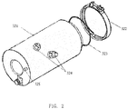
- Fig.2 is a schematic illustrating an APU starter according to one embodiment of the present invention.
- the main portion of the starter 320 is a direct current motor assembly 321, which is coupled to the accessory gearbox 310 via a clamp 322 in a "V" shape and a loop 323 in a "O" shape.
- direct current power connecting posts 324 is connected to a direct current of 28 V and the other to the ground.
- the electrical brush wear indicator 325 there is set a pin visible in a plastic housing. When the indicator pin is displayed, the electrical brush is fine; when the indicator pin is not shown, it is necessary to replace the electrical brush part of the starter.
- the starter system obtains power from the direct current system of the aircraft, supplies a direct current voltage of 28 V to the battery bus (BAT BUS), and the direct current voltage is further supplied to the starter via a contactor.
- the starter system rotates and accelerates the APU rotor to a rotational speed such that the fuel and ignition system may work, and then ignites the fuel to further accelerate the APU.
- the rotational speed reaches 35% to 60% of the normal rotational speed of APU, the starter is shut while the APU continues to accelerate to a normal working rotational speed.
- Fig. 3 is a schematic showing a curve reflecting changes of performance of an APU starter.
- the decline index of the performance of the APU starter is relatively stable, its performance is in the stable phase; when the decline of performance of the APU starter accelerates, it performance enters the decline phase; when the decline index exceeds a certain threshold value, performance of the APU starter enters the failure phase during which malfunction might occur at any time. After the APU starter enters the failure phase, it will not only affect the use of APU and have adverse effect on quality of service and flight safety, but also cause unplanned maintenance and flight delay and grounding.
- Performance of an aircraft APU starter is mainly represented by start time of APU.
- Fig. 4 is a statistical tendency diagram reflecting changes of the APU starting time caused by changes of performance of the APU starter. As shown in Fig. 4 , when the starter is in the stable phase, starting time of the APU changes in a very small scope, however when the APU starter is in the decline phase, starting time of the APU leaps upwardly until the APU cannot be started due to malfunction. In addition, as can be seen from Fig. 4 , the time from the entry into the decline phase to the occurrence of malfunction is very short. Therefore, the detection of decline phase of a starter becomes extremely important.
- the detection of decline phase has the following merits: when an APU starter is in the decline phase, the probability of malfunction remains very low. If the aircraft is maintained at this time, flight safety and quality of service can be guaranteed. At that time, the airline company may arrange inspection and maintenance of the aircraft at an appropriate time so as to avoid unplanned maintenance and reduce flight delay. Meanwhile, excessive costs for maintenance at a regular interval can be avoided.
- the running parameter STA starting time
- the above data can be obtained from data stored in the black box of an aircraft.
- the above data can also be obtained from the data system provided by the aircraft manufacturer, and real-time detection on the ground can be realized.
- running data of an aircraft can be monitored in a real-time manner via both Aircraft Condition Monitoring System (ACMS) of Airbus and Aircraft Heath Monitor (AHM) system of Boeing.
- ACMS Aircraft Condition Monitoring System
- AHM Aircraft Heath Monitor
- a message containing a series of data information can be generated automatically.
- APU-related running data can be obtained via the aircraft data system (such as ACMS or AHM systems) and be embodied in the related generated message.
- Such message information can be transmitted to the ground via the Aircraft Communication Addressing and Reporting System (ACARS) and further be distributed to servers of different airline companies.
- ACARS Aircraft Communication Addressing and Reporting System
- the APU message may also be transmitted via the communication apparatus or system of Aviation Telecommunication Network (ATN).
- ATN Aviation Telecommunication Network
- monitoring the performance of APU is an already-included item, and thus a corresponding APU message can be generated automatically and transmitted to the ground via ACARS or ATN.
- those data monitored are not utilized for detecting the decline phase of performance of APU.
- the A13 message of Airbus namely, APU MES/IDLE REPORT
- the APU message of Boeing is an example of such APU message.
- the A13 message of Airbus is illustrated as an example.
- APU message of Boeing is processed in a similar way.
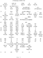
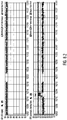
- Fig. 5 illustrates an example of A13 message of Airbus.
- the A13 message mainly contains the following 4 parts of information: the header, the APU history information, the running parameters of starting the aircraft engine and the APU starting parameters.
- the header is composed of CC section and C1 section, mainly including information such as flight information of aircraft, leg in which the message is generated, bleed valve status, total air temperature (i.e., external temperature), and so on.
- the APU history information is comprised of E1 section including APU serial number, service time and circulation and so forth.
- the running parameters for starting an aircraft engine is comprised of N1 to S3 sections; wherein N1 and S1 indicate the running status when the first aircraft engine is started; N2 and S2 indicate the running status when the second aircraft engine is started; N3 and S3 is the status after all engines are started and the APU is idling; wherein data relating to performance of the starter is starting time STA.
- starting time STA the APU running parameter
- the detection of performance of the APU starter of the present invention can be realized by utilizing data obtained in this message.
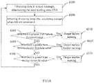
- Fig. 6 is a flow chart illustrating a method for detecting performance of an APU starter according to one embodiment of the present invention. As shown in this figure, in method 6000 for detecting performance of the APU starter, in step 6100, running data such as starting time STA of an APU starter at a certain time point is obtained.
- information needed in step 6100 can be obtained from an APU message such as the A13 message.
- the A13 message of the running of an aircraft APU can be remotely obtained in a real-time manner from SITA (cios Internationale de Telecommunications Aeronautiques) network control center and ADCC (Aviation Data Communication Corporation) network control center, and the obtained A13 message of APU running status can be decoded via a message decoder so as to obtain the required running information of the starter for the Aircraft APU.
- step 6200 the previous M starting times STA are obtained, and their average value AVG and standard deviation ⁇ are calculated.
- the value of M may be 20.
- step 6300 compare whether the standard deviation ⁇ calculated in the previous step exceeds failure threshold value. If yes, then in step 6310, output failure warning.
- step 6300 If the result of the comparison in step 6300 is NO, then go to step 6400, and compare whether the standard deviation ⁇ calculated in step 6200 exceeds the serious decline threshold value. If yes, then in step 6410, output serious decline warning.
- step 6400 If the result of the comparison in step 6400 is NO, then go to step 6500, and compare whether the standard deviation ⁇ calculated in step 6200 exceeds the decline threshold value. If yes, then in step 6510, output decline warning.
- fluctuation of the APU starter of this type in the stable phase is analyzed based on historical data, and other threshold values are further determined based on the volatility in the stable phase.
- the decline threshold value is 1.5 to 2.0 times of the fluctuation in the stable phase
- the failure threshold value is 2 to 3 times of the fluctuation in the stable phase.
- Such method for utilizing data keeping updated in a certain period of time to analyze changes of trend is referred to as moving window method.
- the size of the moving window namely the number M of the points included in the calculation, depends on a number of factors, such as time interval between different measurements and control strategy and so forth. The smaller the moving window is, the easier the volatility of data will be affected by normal fluctuation, and thus various misinformation will occur, which will affect the technical effect of the present invention. If the moving window is overlarge, although the trend of changes will be reflected more accurately, the timeliness of the present invention will be reduced and warning information cannot be delivered timely. Therefore, the size of the moving window plays an important role in the present invention.
- the value of M is around 5 on the condition that 2 to 3 points are measured in each day. According to another embodiment of the present invention, the value of M is around 10 on the condition that the number of points measured in each day is less than or equals to 2.
- the performance of an APU starter is determined to be in the decline phase only if two consecutive decline warnings occurred; while the performance of the APU starter is determined to be in the failure phase only when more than 2 consecutive failure warnings occurred.
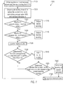
- Fig. 7 is a flow chart illustrating a method for detecting performance of an APU starter according to another embodiment of the present invention. As shown in this figure, in the method 7000 for detecting performance of the APU starter, similar to the embodiment illustrated in Fig. 6 , in step 7100, running data such as starting time STA of an APU starter of an aircraft in a certain service time are obtained.
- step 7200 M starting times STAs before the current time point are obtained and their average value AVG and standard deviation ⁇ are calculated.
- the reason for calculating average value and standard deviation of a certain number of previous points is to set a range of fluctuation for the judgment of the next point, however it is necessary to eliminate values that might be noise.
- high value counter is utilized to record deviation points exceeding the preset range, and when the number of deviation points that consecutively occurred does not reach the warning number, those deviation points will not be included into the sample for calculation of average value and standard deviation.
- the value of M may be 20.
- step 7300 compare whether the standard deviation ⁇ calculated in the previous step exceeds the failure threshold value. If yes, then in step 7310, output failure warning.
- step 7300 When the judgment in step 7300 is NO, then go to step 740, compare whether the standard deviation ⁇ calculated in step 7200 exceeds the decline threshold value. If yes, then in step 7410, output decline warning.
- step 7500 the counter returns to zero. This is because the counting of deviation points is interupted according to the previous judgment, and it is necessary to return the counter to zero so as to recount the number of consecutive deviation points.
- step 7600 determine whether the starting time STA corresponding to the next time point exceeds AVG+n ⁇ .
- the value of n depends on control strategy. When the value of n is relatively high, the control on breakpoint is relatively loose, which may reduce misinformation but has the risk of missing the failure; while when the value of n is relatively low, the control on breakpoint is relatively strict, which may prevent the failure but may generate warnings with high frequency.
- the value of n is between 2 to 5. According to one embodiment of the present invention, the value of n is 3.
- step 7600 When the judgment in step 7600 is YES, then go to step 7610, add 1 to the counter.
- step 7620 determine whether the number on the high value counter equals to the preset warning number. When the determination is NO, return to step 7600. When the determination is YES, it means that some consecutive starting times STAs, the number of which reach the preset warning number, exceed the preset normal range of fluctuation and jump upwardly, then go to step 7630, and send out warning of upward jumping.
- step 7600 When the judgement in step 7600 is No, return to step 7100. It means that the starting time STA is within the normal range and no warning is necessary.
- warning since a single jump might be resulted from various causes, it is required that the warning is output only if the number of jumps consecutively exceeds a certain amount so as to avoid misinformation.
- the value of preset warning number is related to the control strategy, its value is 2 to 5 in general.
- step 7700 the high value counter is returned to zero. This is because when the number of consecutive deviation points reaches the preset warning number, the occurrence of deviation points is not accidental and shall not be eliminated as noise. To return the counter to zero at this time, those deviation points will be retained so as to be included into the reference sample for calculation when recycled to step 7200 next time. Then, return to step 7100 after this step ends.
- Fig. 8 is an example of changes of performance of an APU starter according to one embodiment of the present invention.
- the APU starter is replaced.
- the starting time STA increases rapidly. If using the method descried above, one will find a rapid increase of STA along with a quick increase of deviation index such as standard deviation, and thus a warning of the deterioration of performance of the APU starter and its entry into decline phase will be generated rapidly.
- APU exhaust gas temperature EGT bleed air pressure PT
- angle of inlet guide vane IGV all of which are within the normal range. This is an important feature of the failure of APU starter.
- the deterioration of performance of the APU fuel unit FCU is also similar to the above. Therefore, it shall be distinguished from the failure of fuel control unit: at first, for the standard deviation dispersion of the starting time STA, when the performance of APU fuel unit FCU deteriorates, the speed of deterioration of STA is slow however the performance of STA is good at one time and bad at another, therefore, the area of the dispersion is larger; while during the failure of the starter, it is always the case that STA goes up unilaterally and more rapidly.
- performance of APU fuel unit FCT deteriorates, other parameters except for STA keep good; however, NPA and EGTP will also gradually deteriorate due to unsteady supply of fuel.
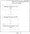
- Fig. 9 is a schematic of the structure of a system for detecting performance of a starter of APU according to one embodiment of the present invention.
- the system for detecting perform of an APU starter comprises: message acquisition unit 901, which obtains message relating to APU within a time period; message parsing unit 902, which parses out the required running data of the APU starter; and performance detection unit 903, which determines whether the performance of the APU starter is in a stable phase, decline phase, serious decline phase or failure phase according to the running data of the starter.
- an apparatus for detecting performance of an APU starter of an aircraft comprises: a processor; and a storage coupled to the processor, wherein the storage stores computer readable instructions; the computer readable instructions run on the processor so as to execute the following steps: obtaining the APU-related messages in a time period; parsing out running parameters of the APU starter according to the message, the running parameters comprise starting time STA; determining whether the performance of the APU starter is in a stable phase, decline phase, serious decline phase or failure phase.
Description
- The present invention relates to a method and an apparatus for detecting performance of the starter of an aircraft auxiliary power unit.
-
EP 2 543 852 A2 -
US 2003/0149550 A1 discloses a system monitoring the performance of aircrafts and generating a warning message when an abnormal situation is detected. The system is operated to manage an entire fleet of aircraft. Data from sensors of each aircraft is sent to a central processing station, where the data is stored in a central database. Incoming data from an aircraft is monitored over a specific number of samples (window). The window is continually monitored to search for alert conditions based on normalized thresholds for specific parameters. An Airborne Auxiliary Power Unit, abbreviated as APU, is a small turbine engine mounted on the tail of an aircraft. Its main function is to supply power and gas sources, with a few APUs capable of providing additive thrust to the aircraft. Specifically, before taking off from the ground, an aircraft may do not need to rely on ground power and gas source vehicles to start the aircraft as its main engine may be started via power supply from the APU. While on the ground, the APU also supplies power and compressed air to ensure lighting and air-conditioning in the cabin and cockpit. During take-off of an aircraft, the APU can serve as a backup power source. After the aircraft is landed, lighting and air-conditioning of the aircraft are still powered by the APU. The functions of APU determine that its stability directly affects flight cost and quality of service of the aircraft. - Ignition of APU is realized via a starter. The structure and cyclic process of the aircraft gas turbine engine decides that it cannot be ignited autonomously. This is because that, if fuel injection and ignition is performed directly in a static engine, the air compressor does not rotate so as to provide pressure to the air and the gas could not move backward to rotate the turbine, in which way the combustion chamber and turbine guide vane will be burnt out. Therefore, the feature for starting the gas turbine engine is: the air flows at first, and then ignition occurs, namely, the engine needs to be rotated firstly and then be started. According to the above feature, before ignition, the engine must be rotated via the starter by consuming electric power.
- The starting of an APU is the process of accelerating the APU rotator from a static state to a stable working state, namely, the working process for the APU rotator to accelerate its rotation speed from 0 to over 95%. During this process, whether the APU rotator may reach a required working rotation speed within a prescribed time and enters into a stable working state mainly depends on the torque the APU rotator obtains during the starting process. As the service time of the starter increases, its efficiency reduces gradually due to the decrease of contact of the carbon brush or increase of internal friction caused by internal field deformation, increasing loss of copper and iron, mechanical wear and the like, and the output power reduces accordingly. When the output power of the starter reduces to a certain degree, the starter cannot provide the APU rotator with an adequate torque, namely failure of the starter occurs.
- APU starter is an important component of APU. Once the starter fails, it will directly cause the APU unable to start, and thus cause the aircraft unable to fly. According to statistics, failure of starter occupies nearly half of the total amount malfunctions of APU, and is a main cause affecting normal operation of APU. It is also a main problem that needs to be solved so as to improve maintenance of APU. Currently, there is not any effective way to maintain the APU starter except for breakdown maintenance. In addition, since performance of the starter deteriorates at a rapid speed (generally speaking, the time for a starter from entering into decline phase to the occurrence of malfunction is basically within 30 hours of flight), there is a need to react to the deterioration of performance of the APU starter rapidly so as to save time to prepare a standby component, which is very important for ensuring on-schedule operation of an aircraft. Meanwhile, it will help to control inventory more accurately, or even realize zero inventory.
- It is the object of the invention to improve maintenance of an APU of an aircraft.
- This object is achieved by the subject matter of
claims - According to one aspect of the present invention, a method for detecting an APU starter comprises: obtaining APU-related messages at multiple time points within a time period; obtaining running parameters of the APU starter according to the messages, the running parameters comprising starting time STA; calculating average value AVG and deviation index δ of the starting time STA within said time period, wherein the deviation index δ is the standard deviation; determining whether performance of the APU starter is in a stable phase, decline phase or failure phase according to the deviation index δ.
- The step for determining whether performance of the APU starter is in a stable phase, decline phase or failure phase comprises: in response to that the deviation index δ is smaller than the decline threshold value, determining that performance of the APU starter is in a stable phase; in response to that the deviation index δ is larger than the decline threshold value and smaller than the failure threshold value, determining that performance of the APU starter is in a decline phase; and in response to that the deviation index δ is larger than the failure threshold value, determining that performance of the APU starter is in a failure phase.
- The method may further comprise determining the deviation index δ when performance of the APU starter is in a stable phase, wherein the decline threshold value is around 1.5 to 2.0 times of the stable deviation index δ, and the failure threshold value is around 2 to 3 times of the stable deviation index δ.
- The time period may be about 2 to 3 days.
- About 5 to 10 APU-related messages may be obtained within said time period.
- The method may further comprise: determining starting time STAnext obtained according to a next APU-related message; in response to that STAnext is larger than AVG+nδ, determining whether STAnext+1 obtained according to a next APU-related message is larger than AVG+nδ; and in response to that the number of times for starting time STA obtained according to APU-related message continuously larger than AVG+nδ exceeds the preset warning number Z, sending out warnings; wherein, n is 2 to 5; and Z is 3 to 5.
- The method may further comprise, in response to that the starting time STA obtained according to APU-related message is smaller than AVG+nδ, recalculating average value AVG and deviation index δ of the starting time STA.
- The method may further comprise, in response to that the number of times for starting time STA obtained according to APU-related message continuously larger than AVG+nδ exceeds the preset warning number Z, recalculating average value AVG and deviation index δ of the starting time STA.
- According to an embodiment n is 2 or 3, and Z is 3.
- The method may further comprise determining that fuel unit of APU works in normal condition.
- The method may further comprise determining that other parameters of APU keep normal, said other parameters comprise but are not limited to: APU exhaust gas temperature EGT, bleed air pressure PT, angle of inlet guide vane IGV and APU turbine efficiency NPA.
- According to another aspect of the present invention, there is provided an apparatus for detecting performance of an APU starter, comprising: a message acquisition unit, which obtains APU-related messages in a time period; a message parsing unit, which parses out the required running data of the APU starter, the running data comprising the starting time STA; and a performance detection unit, which determines whether performance of the APU starter is in a stable phase, decline phase, serious decline phase or failure phase according to the running data of the starter. The performance detection unit calculates the average value AVG and a deviation index δ of the starting time STA within said time period. The deviation index δ is the standard deviation.
- For determining whether performance of the APU starter is in a stable phase, decline phase, serious decline phase or failure phase, the performance detection unit is configured to: in response to that the deviation index δ is smaller than a decline threshold value, determine that performance of the APU starter is in a stable phase; in response to that the deviation index δ is larger than the decline threshold value and smaller than a serious decline threshold value, determine that performance of the APU starter is in a decline phase; in response to that the deviation index δ is larger than the serious decline threshold value and smaller than a failure threshold value, determine that performance of the APU starter is in a serious decline phase; and in response to that the deviation index δ is larger than the failure threshold value, determine that performance of the APU starter is in the failure phase.
- The apparatus for detecting performance of an APU starter may comprise a processor and a storage connected to the processor, wherein the storage stores computer readable codes and the computer readable codes run on the processor so as to execute the following steps: obtaining APU-related messages in a time period; parsing out the running parameters of the APU starter according to the messages, the running parameters comprising starting time STA; determining whether performance of the APU starter is in a stable phase, decline phase, serious decline phase or failure phase.
- Hereinafter, preferred embodiments of the present invention will be further described with reference to the accompany drawings, wherein:
-
Fig.1 is a schematic illustrating the structure of an aircraft APU according to one embodiment of the present invention; -
Fig.2 is a schematic illustrating the structure of an aircraft APU starter according to one embodiment of the present invention; -
Fig.3 is a graph showing a curve reflecting changes of performance of an APU starter according to one embodiment of the present invention; -
Fig.4 is a statistical tendency diagram of data of the starting time of an APU starter; -
Fig.5 is an example of A13 message of Airbus; -
Fig.6 is a flow chart illustrating a method for detecting performance of an APU starter according to one embodiment of the present invention; -
Fig.7 is a flow chart illustrating a method for detecting performance of an APU starter according to another embodiment of the present invention; -
Fig.8 is an example of changes of performance of an APU starter according to one embodiment of the present invention; and -
Fig.9 is a schematic illustrating the structure of a system for detecting performance of an APU starter according to one embodiment of the present invention. - Hereinafter, in order to give a clearer picture of the purposes, technical solutions and advantages of the embodiments of the present invention, the technical solutions in the embodiments of the present invention will be further described, taken in conjunction with the accompanying drawings in the embodiments of the present invention. In the following detailed description, reference is made to the accompanying drawings, which form a part of the present application to illustrate specific embodiments of the application. In the drawings, similar symbols in different drawings identify substantially similar components. With the following detailed description about each specific embodiment of the present application, an ordinary person with relevant knowledge and technology in the art will be able to implement technical solutions of the present application. It should be appreciated that other embodiments may be utilized or changes in structure, logic or electrical property may be made to the embodiments of the present application.
-
Fig.1 is a schematic illustrating the structure of an aircraft APU according to one embodiment of the present invention. As shown in the figure, the aircraft APU mainly comprises apower portion 100, aload portion 200, and anaccessory portion 300, wherein, thepower portion 100 mainly comprises apower compressor 110, aturbine assembly 120, anexhaust assembly 130 and so forth; theload portion 200 mainly comprises aload compressor 210; theaccessory portion 300 mainly comprises anaccessory gearbox 310, astarter 320 and anelectrical generator 330 and so forth. Input air flow from the air inlet diverges into two streams, with one entering thepower compressor 110 andturbine assembly 120 mainly for rotating the APU and then flowing out via theexhaust assembly 130, while another stream entering theload compressor 210 to be pressurized by the load compressor to generate a compressed air exclusively for the use of an aircraft. At the entrance of the airflow, there is provided with a flow regulating valve (inlet guide vane) to regulate opening degree of the valve (vane) in a real-time manner according to compressed air needed by an aircraft so as to control air flow into the load compressor. -
Fig.2 is a schematic illustrating an APU starter according to one embodiment of the present invention. The main portion of thestarter 320 is a directcurrent motor assembly 321, which is coupled to theaccessory gearbox 310 via aclamp 322 in a "V" shape and aloop 323 in a "O" shape. On the directcurrent motor assembly 321, there is provided with direct currentpower connecting posts 324 and electricalbrush wear indicator 325. Generally speaking, one of the twopower connecting posts 324 is connected to a direct current of 28 V and the other to the ground. In the electricalbrush wear indicator 325, there is set a pin visible in a plastic housing. When the indicator pin is displayed, the electrical brush is fine; when the indicator pin is not shown, it is necessary to replace the electrical brush part of the starter. - According to one embodiment of the present invention, the starter system obtains power from the direct current system of the aircraft, supplies a direct current voltage of 28 V to the battery bus (BAT BUS), and the direct current voltage is further supplied to the starter via a contactor. The starter system rotates and accelerates the APU rotor to a rotational speed such that the fuel and ignition system may work, and then ignites the fuel to further accelerate the APU. When the rotational speed reaches 35% to 60% of the normal rotational speed of APU, the starter is shut while the APU continues to accelerate to a normal working rotational speed. For example, for APU of APS3200, when the rotational speed reaches 55% of the normal rotational speed of APU, the starter is shut off; while for APU of GTCP131-9A, when the rotational speed reaches 50% of normal rotational speed of APU, the starter is shut off.
- Changes of performance of a starter follow certain rules: during the early and middle phases of the use of a starter, the performance of the starter is relative stable, while during the later phase, its performance will deteriorate until breakdown.
Fig. 3 is a schematic showing a curve reflecting changes of performance of an APU starter. As can be seen from the figure, as the service time increases, the decline index continues to increase as performance of the APU starter declines gradually. When the decline index of the performance of the APU starter is relatively stable, its performance is in the stable phase; when the decline of performance of the APU starter accelerates, it performance enters the decline phase; when the decline index exceeds a certain threshold value, performance of the APU starter enters the failure phase during which malfunction might occur at any time. After the APU starter enters the failure phase, it will not only affect the use of APU and have adverse effect on quality of service and flight safety, but also cause unplanned maintenance and flight delay and grounding. - Performance of an aircraft APU starter is mainly represented by start time of APU.
Fig. 4 is a statistical tendency diagram reflecting changes of the APU starting time caused by changes of performance of the APU starter. As shown inFig. 4 , when the starter is in the stable phase, starting time of the APU changes in a very small scope, however when the APU starter is in the decline phase, starting time of the APU leaps upwardly until the APU cannot be started due to malfunction. In addition, as can be seen fromFig. 4 , the time from the entry into the decline phase to the occurrence of malfunction is very short. Therefore, the detection of decline phase of a starter becomes extremely important. - In prior art, there is no means for detecting whether the performance of an APU starter is in a decline phase. However, some embodiments of the present invention may realize such detection. The detection of decline phase has the following merits: when an APU starter is in the decline phase, the probability of malfunction remains very low. If the aircraft is maintained at this time, flight safety and quality of service can be guaranteed. At that time, the airline company may arrange inspection and maintenance of the aircraft at an appropriate time so as to avoid unplanned maintenance and reduce flight delay. Meanwhile, excessive costs for maintenance at a regular interval can be avoided.
- Multiple methods can be utilized to obtain the running parameter STA (starting time). For example, the above data can be obtained from data stored in the black box of an aircraft.
- The above data can also be obtained from the data system provided by the aircraft manufacturer, and real-time detection on the ground can be realized. For example, running data of an aircraft can be monitored in a real-time manner via both Aircraft Condition Monitoring System (ACMS) of Airbus and Aircraft Heath Monitor (AHM) system of Boeing. Besides, when certain trigger condition is met, a message containing a series of data information can be generated automatically.
- According to one embodiment of the present invention, APU-related running data can be obtained via the aircraft data system (such as ACMS or AHM systems) and be embodied in the related generated message. Such message information can be transmitted to the ground via the Aircraft Communication Addressing and Reporting System (ACARS) and further be distributed to servers of different airline companies. According to one embodiment of the present invention, the APU message may also be transmitted via the communication apparatus or system of Aviation Telecommunication Network (ATN).
- In fact, for those existing flight data systems, monitoring the performance of APU is an already-included item, and thus a corresponding APU message can be generated automatically and transmitted to the ground via ACARS or ATN. However, those data monitored are not utilized for detecting the decline phase of performance of APU. For example, the A13 message of Airbus (namely, APU MES/IDLE REPORT) or the APU message of Boeing is an example of such APU message. In the following embodiment, the A13 message of Airbus is illustrated as an example. APU message of Boeing is processed in a similar way.
-
Fig. 5 illustrates an example of A13 message of Airbus. As shown in the figure, the A13 message mainly contains the following 4 parts of information: the header, the APU history information, the running parameters of starting the aircraft engine and the APU starting parameters. - The header is composed of CC section and C1 section, mainly including information such as flight information of aircraft, leg in which the message is generated, bleed valve status, total air temperature (i.e., external temperature), and so on. The APU history information is comprised of E1 section including APU serial number, service time and circulation and so forth. The running parameters for starting an aircraft engine is comprised of N1 to S3 sections; wherein N1 and S1 indicate the running status when the first aircraft engine is started; N2 and S2 indicate the running status when the second aircraft engine is started; N3 and S3 is the status after all engines are started and the APU is idling; wherein data relating to performance of the starter is starting time STA.
- As can be seen from
Fig. 5 , starting time STA, the APU running parameter, is included in the existing A13 message. Therefore, the detection of performance of the APU starter of the present invention can be realized by utilizing data obtained in this message. -
Fig. 6 is a flow chart illustrating a method for detecting performance of an APU starter according to one embodiment of the present invention. As shown in this figure, in method 6000 for detecting performance of the APU starter, instep 6100, running data such as starting time STA of an APU starter at a certain time point is obtained. - According to one embodiment of the present invention, information needed in
step 6100 can be obtained from an APU message such as the A13 message. For example, the A13 message of the running of an aircraft APU can be remotely obtained in a real-time manner from SITA (Société Internationale de Telecommunications Aeronautiques) network control center and ADCC (Aviation Data Communication Corporation) network control center, and the obtained A13 message of APU running status can be decoded via a message decoder so as to obtain the required running information of the starter for the Aircraft APU. - In
step 6200, the previous M starting times STA are obtained, and their average value AVG and standard deviation δ are calculated. According one embodiment of the present invention, the value of M may be 20. - In
step 6300, compare whether the standard deviation δ calculated in the previous step exceeds failure threshold value. If yes, then instep 6310, output failure warning. - If the result of the comparison in
step 6300 is NO, then go to step 6400, and compare whether the standard deviation δ calculated instep 6200 exceeds the serious decline threshold value. If yes, then instep 6410, output serious decline warning. - If the result of the comparison in
step 6400 is NO, then go to step 6500, and compare whether the standard deviation δ calculated instep 6200 exceeds the decline threshold value. If yes, then instep 6510, output decline warning. - According to one embodiment of the present invention, fluctuation of the APU starter of this type in the stable phase is analyzed based on historical data, and other threshold values are further determined based on the volatility in the stable phase. For example, according to one embodiment of the present invention, the decline threshold value is 1.5 to 2.0 times of the fluctuation in the stable phase, and the failure threshold value is 2 to 3 times of the fluctuation in the stable phase.
- Such method for utilizing data keeping updated in a certain period of time to analyze changes of trend is referred to as moving window method. The size of the moving window, namely the number M of the points included in the calculation, depends on a number of factors, such as time interval between different measurements and control strategy and so forth. The smaller the moving window is, the easier the volatility of data will be affected by normal fluctuation, and thus various misinformation will occur, which will affect the technical effect of the present invention. If the moving window is overlarge, although the trend of changes will be reflected more accurately, the timeliness of the present invention will be reduced and warning information cannot be delivered timely. Therefore, the size of the moving window plays an important role in the present invention. According to one embodiment of the present invention, the value of M is around 5 on the condition that 2 to 3 points are measured in each day. According to another embodiment of the present invention, the value of M is around 10 on the condition that the number of points measured in each day is less than or equals to 2.
- According to one embodiment of the present invention, in order to reduce false alarm and improve accuracy, the performance of an APU starter is determined to be in the decline phase only if two consecutive decline warnings occurred; while the performance of the APU starter is determined to be in the failure phase only when more than 2 consecutive failure warnings occurred.
-
Fig. 7 is a flow chart illustrating a method for detecting performance of an APU starter according to another embodiment of the present invention. As shown in this figure, in themethod 7000 for detecting performance of the APU starter, similar to the embodiment illustrated inFig. 6 , instep 7100, running data such as starting time STA of an APU starter of an aircraft in a certain service time are obtained. - In
step 7200, M starting times STAs before the current time point are obtained and their average value AVG and standard deviation δ are calculated. The reason for calculating average value and standard deviation of a certain number of previous points is to set a range of fluctuation for the judgment of the next point, however it is necessary to eliminate values that might be noise. According to the following description, high value counter is utilized to record deviation points exceeding the preset range, and when the number of deviation points that consecutively occurred does not reach the warning number, those deviation points will not be included into the sample for calculation of average value and standard deviation. According to one embodiment of the present invention, the value of M may be 20. - In
step 7300, compare whether the standard deviation δ calculated in the previous step exceeds the failure threshold value. If yes, then instep 7310, output failure warning. - When the judgment in
step 7300 is NO, then go to step 740, compare whether the standard deviation δ calculated instep 7200 exceeds the decline threshold value. If yes, then instep 7410, output decline warning. - When the judgment in
step 7400 is NO, then go to step 7500, the counter returns to zero. This is because the counting of deviation points is interupted according to the previous judgment, and it is necessary to return the counter to zero so as to recount the number of consecutive deviation points. - In
step 7600, determine whether the starting time STA corresponding to the next time point exceeds AVG+nδ. Wherein, the value of n depends on control strategy. When the value of n is relatively high, the control on breakpoint is relatively loose, which may reduce misinformation but has the risk of missing the failure; while when the value of n is relatively low, the control on breakpoint is relatively strict, which may prevent the failure but may generate warnings with high frequency. Generally speaking, the value of n is between 2 to 5. According to one embodiment of the present invention, the value of n is 3. - When the judgment in
step 7600 is YES, then go to step 7610, add 1 to the counter. Next, instep 7620, determine whether the number on the high value counter equals to the preset warning number. When the determination is NO, return tostep 7600. When the determination is YES, it means that some consecutive starting times STAs, the number of which reach the preset warning number, exceed the preset normal range of fluctuation and jump upwardly, then go to step 7630, and send out warning of upward jumping. - When the judgement in
step 7600 is No, return tostep 7100. It means that the starting time STA is within the normal range and no warning is necessary. - According to one embodiment of the present invention, since a single jump might be resulted from various causes, it is required that the warning is output only if the number of jumps consecutively exceeds a certain amount so as to avoid misinformation. The value of preset warning number is related to the control strategy, its value is 2 to 5 in general.
- In
step 7700, the high value counter is returned to zero. This is because when the number of consecutive deviation points reaches the preset warning number, the occurrence of deviation points is not accidental and shall not be eliminated as noise. To return the counter to zero at this time, those deviation points will be retained so as to be included into the reference sample for calculation when recycled to step 7200 next time. Then, return to step 7100 after this step ends. -
Fig. 8 is an example of changes of performance of an APU starter according to one embodiment of the present invention. At the position marked by solid line in the figure, the APU starter is replaced. As shown inFig. 8 , before the replacement of the APU starter, the starting time STA increases rapidly. If using the method descried above, one will find a rapid increase of STA along with a quick increase of deviation index such as standard deviation, and thus a warning of the deterioration of performance of the APU starter and its entry into decline phase will be generated rapidly. - Meanwhile, it shall also be noted that other parameters of APU except for the starting time STA keep normal, therein the said other parameters comprise but are not limited to: APU exhaust gas temperature EGT, bleed air pressure PT, angle of inlet guide vane IGV, all of which are within the normal range. This is an important feature of the failure of APU starter.
- It shall also be noted that the deterioration of performance of the APU fuel unit FCU is also similar to the above. Therefore, it shall be distinguished from the failure of fuel control unit: at first, for the standard deviation dispersion of the starting time STA, when the performance of APU fuel unit FCU deteriorates, the speed of deterioration of STA is slow however the performance of STA is good at one time and bad at another, therefore, the area of the dispersion is larger; while during the failure of the starter, it is always the case that STA goes up unilaterally and more rapidly. Besides, although performance of APU fuel unit FCT deteriorates, other parameters except for STA keep good; however, NPA and EGTP will also gradually deteriorate due to unsteady supply of fuel.
-
Fig. 9 is a schematic of the structure of a system for detecting performance of a starter of APU according to one embodiment of the present invention. As shown inFig. 9 , the system for detecting perform of an APU starter comprises:message acquisition unit 901, which obtains message relating to APU within a time period;message parsing unit 902, which parses out the required running data of the APU starter; andperformance detection unit 903, which determines whether the performance of the APU starter is in a stable phase, decline phase, serious decline phase or failure phase according to the running data of the starter. - According to one embodiment of the present invention, an apparatus for detecting performance of an APU starter of an aircraft comprises: a processor; and a storage coupled to the processor, wherein the storage stores computer readable instructions; the computer readable instructions run on the processor so as to execute the following steps: obtaining the APU-related messages in a time period; parsing out running parameters of the APU starter according to the message, the running parameters comprise starting time STA; determining whether the performance of the APU starter is in a stable phase, decline phase, serious decline phase or failure phase.
- The above embodiments are only described for illustrating the present invention, and do not mean to limit the present invention. A person with ordinary skill in relevant art may make various changes and variations without departing from the scope of the present invention as defined by the claims.
Claims (11)
- A method for detecting performance of an APU starter (320), comprising:obtaining APU-related messages at multiple time points within one time period;obtaining running parameters of the APU starter (320) according to the messages, the running parameters comprise starting time STA;calculating the average value AVG and a deviation index δ of the starting time STA within said time period, the deviation index δ being the standard deviation; anddetermining whether performance of the APU starter (320) is in a stable phase, decline phase, or failure phase according to the deviation index δ,wherein the step of determining whether performance of the APU starter (320) is in a stable phase, decline phase, or failure phase comprises:in response to that the deviation index δ is smaller than a decline threshold value, determining that performance of the APU starter (320) is in a stable phase;in response to that the deviation index δ is larger than the decline threshold value and smaller than a failure threshold value, determining that performance of the APU starter (320) is in a decline phase; andin response to that the deviation index δ is larger than the failure threshold value, determining that performance of the APU starter (320) is in the failure phase.
- The method of Claim 1, further comprising:determining the deviation index δ when the APU starter (320) is in a stable phase;wherein, the decline threshold value is about 1.5 to 2.0 times of the stable deviation index δ, and failure threshold value is about 2 to 3 times of the stable deviation index δ.
- The method of Claim 1 or 2, wherein the time period is around 2 to 3 days.
- The method of any one of the preceding claims, wherein around 5 to 10 APU-related messages are obtained within the time period.
- The method of any one of the preceding claims, further comprising:determining starting time STAnext obtained according to a next APU-related message;in response to that STAnext is larger than AVG+nδ, determining whether STAnext+1 obtained from a next APU-related message is larger than AVG+nδ; andin response to that the number of times for starting time STA obtained according to APU-related message continuously larger than AVG+nδ exceeds the preset warning number Z, sending out a warning;wherein, n is 2 to 5; Z is 3 to 5.
- The method of Claim 5, further comprising, in response to that starting time STA obtained according to APU-related messages is smaller than AVG+nδ, recalculating average value AVG and deviation index δ of the starting time STA.
- The method of Claim 5, further comprising, in response to that the number of times for starting time STA obtained according to APU-related message continuously larger than AVG+nδ exceeds the preset warning number Z, recalculating average value AVG and deviation index δ of the starting time STA.
- The method of any one of claims 5 to 7, wherein n is 2 or 3, and Z is 3.
- The method of any one of the preceding claims, further comprising: determining that fuel unit of APU works in normal condition.
- The method of any one of the preceding claims, further comprising: determining that other parameters of APU keep normal, the other parameters comprise but are not limited to: APU exhaust gas temperature EGT, bleed air pressure PT, angle of inlet guide vane IGV and APU turbine efficiency NPA.
- An apparatus for detecting performance of an APU starter (320), comprising:a message acquisition unit (901), which is configured to obtain APU-related messages within a time period;a message parsing unit (902), which is configured to parse out required running data of APU starter (320), the running data comprising starting time STA; anda performance detection unit (903), which is configured to calculate the average value AVG and a deviation index δ of the starting time STA within said time period, the deviation index δ being the standard deviation, and to determine whether performance of the APU starter (320) is in a stable phase, decline phase, serious decline phase or failure phase according to the running data of the starter,wherein for determining whether performance of the APU starter (320) is in a stable phase, decline phase, serious decline phase or failure phase, the performance detection unit (903) is configured to:in response to that the deviation index δ is smaller than a decline threshold value, determine that performance of the APU starter (320) is in a stable phase;in response to that the deviation index δ is larger than the decline threshold value and smaller than a serious decline threshold value, determine that performance of the APU starter (320) is in a decline phase;in response to that the deviation index δ is larger than the serious decline threshold value and smaller than a failure threshold value, determine that performance of the APU starter (320) is in a serious decline phase; andin response to that the deviation index δ is larger than the failure threshold value, determine that performance of the APU starter (320) is in the failure phase.
Applications Claiming Priority (1)
| Application Number | Priority Date | Filing Date | Title |
|---|---|---|---|
| CN201310313849.XA CN104345273B (en) | 2013-07-24 | 2013-07-24 | Airplane auxiliary power unit starter method for testing performance and device |
Publications (3)
| Publication Number | Publication Date |
|---|---|
| EP2829721A2 EP2829721A2 (en) | 2015-01-28 |
| EP2829721A3 EP2829721A3 (en) | 2016-11-30 |
| EP2829721B1 true EP2829721B1 (en) | 2019-04-17 |
Family
ID=51260606
Family Applications (1)
| Application Number | Title | Priority Date | Filing Date |
|---|---|---|---|
| EP14178339.9A Active EP2829721B1 (en) | 2013-07-24 | 2014-07-24 | Method and apparatus for detecting performance of an APU starter |
Country Status (10)
| Country | Link |
|---|---|
| US (1) | US9581124B2 (en) |
| EP (1) | EP2829721B1 (en) |
| JP (1) | JP6205320B2 (en) |
| KR (1) | KR102004004B1 (en) |
| CN (1) | CN104345273B (en) |
| AU (1) | AU2014206172B2 (en) |
| CA (1) | CA2857781C (en) |
| HK (1) | HK1202337A1 (en) |
| SG (1) | SG10201404362XA (en) |
| TW (1) | TWI625274B (en) |
Families Citing this family (16)
| Publication number | Priority date | Publication date | Assignee | Title |
|---|---|---|---|---|
| CN104348670B (en) * | 2013-07-24 | 2018-01-30 | 中国国际航空股份有限公司 | Airplane auxiliary power unit fuel oil assembly property detection method and device |
| CN104340369B (en) * | 2013-07-24 | 2017-03-08 | 中国国际航空股份有限公司 | Airplane auxiliary power unit oil cooler method for monitoring performance and device |
| CN106121829B (en) * | 2016-08-18 | 2018-01-23 | 四川泛华航空仪表电器有限公司 | Monitor the fault-preventing device of engine ignitor working condition |
| CN106226060B (en) * | 2016-08-30 | 2019-02-05 | 成都飞亚航空设备应用研究所有限公司 | Aircraft auxiliary power plant test macro |
| CN106527391B (en) * | 2016-10-18 | 2018-11-16 | 中国航空工业集团公司洛阳电光设备研究所 | Rotating mechanism control system self-sensing method in a kind of airborne photoelectric detecting devices |
| CN108825384B (en) * | 2018-08-27 | 2023-10-20 | 西安觉天动力科技有限责任公司 | Oil-gas mixing starting device |
| US11780609B2 (en) | 2019-06-12 | 2023-10-10 | Honeywell International Inc. | Maintenance recommendations using lifecycle clustering |
| CN110341986B (en) * | 2019-07-16 | 2021-07-20 | 哈尔滨工业大学 | Multi-step prediction method for performance parameters of airplane auxiliary power device based on RBM (radial basis function) optimization ELM (electric field model) |
| JP7285372B2 (en) * | 2019-10-25 | 2023-06-01 | ケーエムダブリュ・インコーポレーテッド | Antenna clamping device |
| KR102269214B1 (en) * | 2019-10-25 | 2021-06-28 | 주식회사 케이엠더블유 | Clamping apparatus for antenna device |
| CN111693180B (en) * | 2020-05-27 | 2021-07-23 | 中国航空工业集团公司西安航空计算技术研究所 | Exhaust temperature over-temperature fault detection method for auxiliary power system |
| CN111746806B (en) * | 2020-06-15 | 2023-06-23 | 西安爱生技术集团公司 | Unmanned aerial vehicle heuristic system and integrated control method |
| CN111814393B (en) * | 2020-06-29 | 2022-04-12 | 哈尔滨工业大学 | APU (auxiliary Power Unit) degradation parameter generation method based on generation countermeasure network |
| CN112211725B (en) * | 2020-09-11 | 2023-03-24 | 中国航空工业集团公司成都飞机设计研究所 | Auxiliary energy control system and control method suitable for unmanned aerial vehicle |
| CN112268036B (en) * | 2020-10-16 | 2023-03-24 | 中国直升机设计研究所 | Device for simulating starting load of helicopter APU |
| CN116147921B (en) * | 2023-04-21 | 2023-07-07 | 南方电网调峰调频发电有限公司检修试验分公司 | Water pumping starting test method, device and equipment for water pumping energy storage engine |
Family Cites Families (11)
| Publication number | Priority date | Publication date | Assignee | Title |
|---|---|---|---|---|
| JPS6066647A (en) * | 1983-09-20 | 1985-04-16 | Sumitomo Metal Ind Ltd | Diagnosing method of motor |
| US6845306B2 (en) * | 2000-11-09 | 2005-01-18 | Honeywell International Inc. | System and method for performance monitoring of operational equipment used with machines |
| US6732063B2 (en) * | 2002-02-01 | 2004-05-04 | National Research Council Of Canada | Method of identifying abnormal behavior in a fleet of vehicles |
| US7693643B2 (en) * | 2005-02-14 | 2010-04-06 | Honeywell International Inc. | Fault detection system and method for turbine engine fuel systems |
| US7878910B2 (en) * | 2005-09-13 | 2011-02-01 | Igt | Gaming machine with scanning 3-D display system |
| US7369932B2 (en) * | 2006-05-04 | 2008-05-06 | Honeywell International, Inc. | System and method for turbine engine fault detection using discrete event system modeling |
| ES2363897B1 (en) * | 2008-10-24 | 2012-07-04 | Airbus Operations, S.L. | AUXILIARY POWER UNIT (APU) OF AN AIRCRAFT |
| CN102343983A (en) * | 2011-07-07 | 2012-02-08 | 中国国际航空股份有限公司 | Airplane APU (Auxiliary Power Unit) performance detecting method |
| CN102320382A (en) * | 2011-07-07 | 2012-01-18 | 中国国际航空股份有限公司 | Aircraft performance detection method |
| CN102416821A (en) * | 2011-07-27 | 2012-04-18 | 中国国际航空股份有限公司 | Aircraft system data processing method |
| KR101330804B1 (en) * | 2012-06-26 | 2013-11-18 | 창원대학교 산학협력단 | Fault detect apparatus for three phase alternating-current motor and method thereof |
-
2013
- 2013-07-24 CN CN201310313849.XA patent/CN104345273B/en active Active
-
2014
- 2014-07-23 US US14/338,565 patent/US9581124B2/en active Active
- 2014-07-24 SG SG10201404362XA patent/SG10201404362XA/en unknown
- 2014-07-24 KR KR1020140094099A patent/KR102004004B1/en active IP Right Grant
- 2014-07-24 AU AU2014206172A patent/AU2014206172B2/en active Active
- 2014-07-24 JP JP2014151115A patent/JP6205320B2/en active Active
- 2014-07-24 EP EP14178339.9A patent/EP2829721B1/en active Active
- 2014-07-24 CA CA2857781A patent/CA2857781C/en active Active
- 2014-07-24 TW TW103125398A patent/TWI625274B/en active
-
2015
- 2015-03-18 HK HK15102799.2A patent/HK1202337A1/en unknown
Non-Patent Citations (1)
| Title |
|---|
| None * |
Also Published As
| Publication number | Publication date |
|---|---|
| CA2857781A1 (en) | 2015-01-24 |
| EP2829721A3 (en) | 2016-11-30 |
| US20160230737A1 (en) | 2016-08-11 |
| TW201515934A (en) | 2015-05-01 |
| SG10201404362XA (en) | 2015-02-27 |
| JP2015038347A (en) | 2015-02-26 |
| CN104345273A (en) | 2015-02-11 |
| KR102004004B1 (en) | 2019-07-25 |
| HK1202337A1 (en) | 2015-09-25 |
| AU2014206172B2 (en) | 2017-11-02 |
| EP2829721A2 (en) | 2015-01-28 |
| CA2857781C (en) | 2019-01-22 |
| AU2014206172A1 (en) | 2015-02-12 |
| TWI625274B (en) | 2018-06-01 |
| KR20150012221A (en) | 2015-02-03 |
| JP6205320B2 (en) | 2017-09-27 |
| CN104345273B (en) | 2017-11-24 |
| US9581124B2 (en) | 2017-02-28 |
Similar Documents
| Publication | Publication Date | Title |
|---|---|---|
| EP2829721B1 (en) | Method and apparatus for detecting performance of an APU starter | |
| CA2857785C (en) | Method and apparatus for detecting performance of an apu fuel assembly | |
| EP2543852B1 (en) | Method for assessing the performance of auxiliary power unit | |
| EP2829688B1 (en) | Method and device for monitoring an APU turbine | |
| TWI625271B (en) | Aircraft auxiliary power unit turbine efficiency monitoring method and device |
Legal Events
| Date | Code | Title | Description |
|---|---|---|---|
| 17P | Request for examination filed |
Effective date: 20140724 |
|
| AK | Designated contracting states |
Kind code of ref document: A2 Designated state(s): AL AT BE BG CH CY CZ DE DK EE ES FI FR GB GR HR HU IE IS IT LI LT LU LV MC MK MT NL NO PL PT RO RS SE SI SK SM TR |
|
| AX | Request for extension of the european patent |
Extension state: BA ME |
|
| PUAI | Public reference made under article 153(3) epc to a published international application that has entered the european phase |
Free format text: ORIGINAL CODE: 0009012 |
|
| PUAL | Search report despatched |
Free format text: ORIGINAL CODE: 0009013 |
|
| AK | Designated contracting states |
Kind code of ref document: A3 Designated state(s): AL AT BE BG CH CY CZ DE DK EE ES FI FR GB GR HR HU IE IS IT LI LT LU LV MC MK MT NL NO PL PT RO RS SE SI SK SM TR |
|
| AX | Request for extension of the european patent |
Extension state: BA ME |
|
| RIC1 | Information provided on ipc code assigned before grant |
Ipc: G05B 23/02 20060101ALI20161021BHEP Ipc: B64D 41/00 20060101ALI20161021BHEP Ipc: F02N 11/10 20060101AFI20161021BHEP Ipc: F02C 7/268 20060101ALI20161021BHEP |
|
| STAA | Information on the status of an ep patent application or granted ep patent |
Free format text: STATUS: REQUEST FOR EXAMINATION WAS MADE |
|
| R17P | Request for examination filed (corrected) |
Effective date: 20170530 |
|
| RBV | Designated contracting states (corrected) |
Designated state(s): AL AT BE BG CH CY CZ DE DK EE ES FI FR GB GR HR HU IE IS IT LI LT LU LV MC MK MT NL NO PL PT RO RS SE SI SK SM TR |
|
| GRAP | Despatch of communication of intention to grant a patent |
Free format text: ORIGINAL CODE: EPIDOSNIGR1 |
|
| STAA | Information on the status of an ep patent application or granted ep patent |
Free format text: STATUS: GRANT OF PATENT IS INTENDED |
|
| INTG | Intention to grant announced |
Effective date: 20190114 |
|
| GRAS | Grant fee paid |
Free format text: ORIGINAL CODE: EPIDOSNIGR3 |
|
| GRAA | (expected) grant |
Free format text: ORIGINAL CODE: 0009210 |
|
| STAA | Information on the status of an ep patent application or granted ep patent |
Free format text: STATUS: THE PATENT HAS BEEN GRANTED |
|
| AK | Designated contracting states |
Kind code of ref document: B1 Designated state(s): AL AT BE BG CH CY CZ DE DK EE ES FI FR GB GR HR HU IE IS IT LI LT LU LV MC MK MT NL NO PL PT RO RS SE SI SK SM TR |
|
| REG | Reference to a national code |
Ref country code: GB Ref legal event code: FG4D |
|
| REG | Reference to a national code |
Ref country code: CH Ref legal event code: EP |
|
| REG | Reference to a national code |
Ref country code: DE Ref legal event code: R096 Ref document number: 602014044795 Country of ref document: DE |
|
| REG | Reference to a national code |
Ref country code: AT Ref legal event code: REF Ref document number: 1121824 Country of ref document: AT Kind code of ref document: T Effective date: 20190515 Ref country code: IE Ref legal event code: FG4D |
|
| REG | Reference to a national code |
Ref country code: NL Ref legal event code: MP Effective date: 20190417 |
|
| REG | Reference to a national code |
Ref country code: LT Ref legal event code: MG4D |
|
| PG25 | Lapsed in a contracting state [announced via postgrant information from national office to epo] |
Ref country code: NL Free format text: LAPSE BECAUSE OF FAILURE TO SUBMIT A TRANSLATION OF THE DESCRIPTION OR TO PAY THE FEE WITHIN THE PRESCRIBED TIME-LIMIT Effective date: 20190417 |
|
| PG25 | Lapsed in a contracting state [announced via postgrant information from national office to epo] |
Ref country code: ES Free format text: LAPSE BECAUSE OF FAILURE TO SUBMIT A TRANSLATION OF THE DESCRIPTION OR TO PAY THE FEE WITHIN THE PRESCRIBED TIME-LIMIT Effective date: 20190417 Ref country code: HR Free format text: LAPSE BECAUSE OF FAILURE TO SUBMIT A TRANSLATION OF THE DESCRIPTION OR TO PAY THE FEE WITHIN THE PRESCRIBED TIME-LIMIT Effective date: 20190417 Ref country code: LT Free format text: LAPSE BECAUSE OF FAILURE TO SUBMIT A TRANSLATION OF THE DESCRIPTION OR TO PAY THE FEE WITHIN THE PRESCRIBED TIME-LIMIT Effective date: 20190417 Ref country code: NO Free format text: LAPSE BECAUSE OF FAILURE TO SUBMIT A TRANSLATION OF THE DESCRIPTION OR TO PAY THE FEE WITHIN THE PRESCRIBED TIME-LIMIT Effective date: 20190717 Ref country code: SE Free format text: LAPSE BECAUSE OF FAILURE TO SUBMIT A TRANSLATION OF THE DESCRIPTION OR TO PAY THE FEE WITHIN THE PRESCRIBED TIME-LIMIT Effective date: 20190417 Ref country code: PT Free format text: LAPSE BECAUSE OF FAILURE TO SUBMIT A TRANSLATION OF THE DESCRIPTION OR TO PAY THE FEE WITHIN THE PRESCRIBED TIME-LIMIT Effective date: 20190817 Ref country code: AL Free format text: LAPSE BECAUSE OF FAILURE TO SUBMIT A TRANSLATION OF THE DESCRIPTION OR TO PAY THE FEE WITHIN THE PRESCRIBED TIME-LIMIT Effective date: 20190417 Ref country code: FI Free format text: LAPSE BECAUSE OF FAILURE TO SUBMIT A TRANSLATION OF THE DESCRIPTION OR TO PAY THE FEE WITHIN THE PRESCRIBED TIME-LIMIT Effective date: 20190417 |
|
| PG25 | Lapsed in a contracting state [announced via postgrant information from national office to epo] |
Ref country code: LV Free format text: LAPSE BECAUSE OF FAILURE TO SUBMIT A TRANSLATION OF THE DESCRIPTION OR TO PAY THE FEE WITHIN THE PRESCRIBED TIME-LIMIT Effective date: 20190417 Ref country code: RS Free format text: LAPSE BECAUSE OF FAILURE TO SUBMIT A TRANSLATION OF THE DESCRIPTION OR TO PAY THE FEE WITHIN THE PRESCRIBED TIME-LIMIT Effective date: 20190417 Ref country code: PL Free format text: LAPSE BECAUSE OF FAILURE TO SUBMIT A TRANSLATION OF THE DESCRIPTION OR TO PAY THE FEE WITHIN THE PRESCRIBED TIME-LIMIT Effective date: 20190417 Ref country code: GR Free format text: LAPSE BECAUSE OF FAILURE TO SUBMIT A TRANSLATION OF THE DESCRIPTION OR TO PAY THE FEE WITHIN THE PRESCRIBED TIME-LIMIT Effective date: 20190718 Ref country code: BG Free format text: LAPSE BECAUSE OF FAILURE TO SUBMIT A TRANSLATION OF THE DESCRIPTION OR TO PAY THE FEE WITHIN THE PRESCRIBED TIME-LIMIT Effective date: 20190717 |
|
| REG | Reference to a national code |
Ref country code: AT Ref legal event code: MK05 Ref document number: 1121824 Country of ref document: AT Kind code of ref document: T Effective date: 20190417 |
|
| PG25 | Lapsed in a contracting state [announced via postgrant information from national office to epo] |
Ref country code: IS Free format text: LAPSE BECAUSE OF FAILURE TO SUBMIT A TRANSLATION OF THE DESCRIPTION OR TO PAY THE FEE WITHIN THE PRESCRIBED TIME-LIMIT Effective date: 20190817 |
|
| REG | Reference to a national code |
Ref country code: DE Ref legal event code: R097 Ref document number: 602014044795 Country of ref document: DE |
|
| PG25 | Lapsed in a contracting state [announced via postgrant information from national office to epo] |
Ref country code: CZ Free format text: LAPSE BECAUSE OF FAILURE TO SUBMIT A TRANSLATION OF THE DESCRIPTION OR TO PAY THE FEE WITHIN THE PRESCRIBED TIME-LIMIT Effective date: 20190417 Ref country code: RO Free format text: LAPSE BECAUSE OF FAILURE TO SUBMIT A TRANSLATION OF THE DESCRIPTION OR TO PAY THE FEE WITHIN THE PRESCRIBED TIME-LIMIT Effective date: 20190417 Ref country code: SK Free format text: LAPSE BECAUSE OF FAILURE TO SUBMIT A TRANSLATION OF THE DESCRIPTION OR TO PAY THE FEE WITHIN THE PRESCRIBED TIME-LIMIT Effective date: 20190417 Ref country code: EE Free format text: LAPSE BECAUSE OF FAILURE TO SUBMIT A TRANSLATION OF THE DESCRIPTION OR TO PAY THE FEE WITHIN THE PRESCRIBED TIME-LIMIT Effective date: 20190417 Ref country code: DK Free format text: LAPSE BECAUSE OF FAILURE TO SUBMIT A TRANSLATION OF THE DESCRIPTION OR TO PAY THE FEE WITHIN THE PRESCRIBED TIME-LIMIT Effective date: 20190417 Ref country code: AT Free format text: LAPSE BECAUSE OF FAILURE TO SUBMIT A TRANSLATION OF THE DESCRIPTION OR TO PAY THE FEE WITHIN THE PRESCRIBED TIME-LIMIT Effective date: 20190417 |
|
| PLBE | No opposition filed within time limit |
Free format text: ORIGINAL CODE: 0009261 |
|
| STAA | Information on the status of an ep patent application or granted ep patent |
Free format text: STATUS: NO OPPOSITION FILED WITHIN TIME LIMIT |
|
| PG25 | Lapsed in a contracting state [announced via postgrant information from national office to epo] |
Ref country code: MC Free format text: LAPSE BECAUSE OF FAILURE TO SUBMIT A TRANSLATION OF THE DESCRIPTION OR TO PAY THE FEE WITHIN THE PRESCRIBED TIME-LIMIT Effective date: 20190417 Ref country code: SM Free format text: LAPSE BECAUSE OF FAILURE TO SUBMIT A TRANSLATION OF THE DESCRIPTION OR TO PAY THE FEE WITHIN THE PRESCRIBED TIME-LIMIT Effective date: 20190417 Ref country code: IT Free format text: LAPSE BECAUSE OF FAILURE TO SUBMIT A TRANSLATION OF THE DESCRIPTION OR TO PAY THE FEE WITHIN THE PRESCRIBED TIME-LIMIT Effective date: 20190417 |
|
| REG | Reference to a national code |
Ref country code: CH Ref legal event code: PL |
|
| 26N | No opposition filed |
Effective date: 20200120 |
|
| PG25 | Lapsed in a contracting state [announced via postgrant information from national office to epo] |
Ref country code: TR Free format text: LAPSE BECAUSE OF FAILURE TO SUBMIT A TRANSLATION OF THE DESCRIPTION OR TO PAY THE FEE WITHIN THE PRESCRIBED TIME-LIMIT Effective date: 20190417 |
|
| REG | Reference to a national code |
Ref country code: BE Ref legal event code: MM Effective date: 20190731 |
|
| PG25 | Lapsed in a contracting state [announced via postgrant information from national office to epo] |
Ref country code: LU Free format text: LAPSE BECAUSE OF NON-PAYMENT OF DUE FEES Effective date: 20190724 Ref country code: LI Free format text: LAPSE BECAUSE OF NON-PAYMENT OF DUE FEES Effective date: 20190731 Ref country code: CH Free format text: LAPSE BECAUSE OF NON-PAYMENT OF DUE FEES Effective date: 20190731 Ref country code: BE Free format text: LAPSE BECAUSE OF NON-PAYMENT OF DUE FEES Effective date: 20190731 Ref country code: SI Free format text: LAPSE BECAUSE OF FAILURE TO SUBMIT A TRANSLATION OF THE DESCRIPTION OR TO PAY THE FEE WITHIN THE PRESCRIBED TIME-LIMIT Effective date: 20190417 |
|
| PG25 | Lapsed in a contracting state [announced via postgrant information from national office to epo] |
Ref country code: IE Free format text: LAPSE BECAUSE OF NON-PAYMENT OF DUE FEES Effective date: 20190724 |
|
| PG25 | Lapsed in a contracting state [announced via postgrant information from national office to epo] |
Ref country code: CY Free format text: LAPSE BECAUSE OF FAILURE TO SUBMIT A TRANSLATION OF THE DESCRIPTION OR TO PAY THE FEE WITHIN THE PRESCRIBED TIME-LIMIT Effective date: 20190417 |
|
| PG25 | Lapsed in a contracting state [announced via postgrant information from national office to epo] |
Ref country code: MT Free format text: LAPSE BECAUSE OF FAILURE TO SUBMIT A TRANSLATION OF THE DESCRIPTION OR TO PAY THE FEE WITHIN THE PRESCRIBED TIME-LIMIT Effective date: 20190417 Ref country code: HU Free format text: LAPSE BECAUSE OF FAILURE TO SUBMIT A TRANSLATION OF THE DESCRIPTION OR TO PAY THE FEE WITHIN THE PRESCRIBED TIME-LIMIT; INVALID AB INITIO Effective date: 20140724 |
|
| PG25 | Lapsed in a contracting state [announced via postgrant information from national office to epo] |
Ref country code: MK Free format text: LAPSE BECAUSE OF FAILURE TO SUBMIT A TRANSLATION OF THE DESCRIPTION OR TO PAY THE FEE WITHIN THE PRESCRIBED TIME-LIMIT Effective date: 20190417 |
|
| PGFP | Annual fee paid to national office [announced via postgrant information from national office to epo] |
Ref country code: FR Payment date: 20230502 Year of fee payment: 10 |
|
| PGFP | Annual fee paid to national office [announced via postgrant information from national office to epo] |
Ref country code: GB Payment date: 20230504 Year of fee payment: 10 |
|
| PGFP | Annual fee paid to national office [announced via postgrant information from national office to epo] |
Ref country code: DE Payment date: 20230426 Year of fee payment: 10 |