EP2829684A1 - Electronically-actuated, multi-set straddle borehole treatment apparatus - Google Patents
Electronically-actuated, multi-set straddle borehole treatment apparatus Download PDFInfo
- Publication number
- EP2829684A1 EP2829684A1 EP14178652.5A EP14178652A EP2829684A1 EP 2829684 A1 EP2829684 A1 EP 2829684A1 EP 14178652 A EP14178652 A EP 14178652A EP 2829684 A1 EP2829684 A1 EP 2829684A1
- Authority
- EP
- European Patent Office
- Prior art keywords
- valve
- packer
- flow
- packers
- fluid communication
- Prior art date
- Legal status (The legal status is an assumption and is not a legal conclusion. Google has not performed a legal analysis and makes no representation as to the accuracy of the status listed.)
- Granted
Links
- 239000012530 fluid Substances 0.000 claims abstract description 102
- 238000004891 communication Methods 0.000 claims abstract description 66
- 230000004913 activation Effects 0.000 claims description 46
- 230000004044 response Effects 0.000 claims description 28
- 238000000034 method Methods 0.000 claims description 26
- 230000000977 initiatory effect Effects 0.000 claims description 16
- 230000003213 activating effect Effects 0.000 claims description 5
- 238000005086 pumping Methods 0.000 claims description 4
- 238000001514 detection method Methods 0.000 claims description 2
- 230000015572 biosynthetic process Effects 0.000 abstract description 5
- 238000002955 isolation Methods 0.000 description 17
- 230000007246 mechanism Effects 0.000 description 11
- 239000000126 substance Substances 0.000 description 6
- 208000010392 Bone Fractures Diseases 0.000 description 5
- 206010017076 Fracture Diseases 0.000 description 5
- 238000012856 packing Methods 0.000 description 5
- 230000009849 deactivation Effects 0.000 description 4
- 230000002441 reversible effect Effects 0.000 description 4
- 230000009471 action Effects 0.000 description 3
- 239000000700 radioactive tracer Substances 0.000 description 3
- 230000005355 Hall effect Effects 0.000 description 2
- 230000006870 function Effects 0.000 description 2
- 230000002285 radioactive effect Effects 0.000 description 2
- BVKZGUZCCUSVTD-UHFFFAOYSA-L Carbonate Chemical compound [O-]C([O-])=O BVKZGUZCCUSVTD-UHFFFAOYSA-L 0.000 description 1
- 239000002253 acid Substances 0.000 description 1
- 238000010306 acid treatment Methods 0.000 description 1
- 230000004075 alteration Effects 0.000 description 1
- 230000008901 benefit Effects 0.000 description 1
- 230000005540 biological transmission Effects 0.000 description 1
- 239000004568 cement Substances 0.000 description 1
- 238000005260 corrosion Methods 0.000 description 1
- 230000007797 corrosion Effects 0.000 description 1
- 230000003111 delayed effect Effects 0.000 description 1
- 238000013461 design Methods 0.000 description 1
- 230000000694 effects Effects 0.000 description 1
- 230000005611 electricity Effects 0.000 description 1
- 238000005516 engineering process Methods 0.000 description 1
- 230000003628 erosive effect Effects 0.000 description 1
- 238000001914 filtration Methods 0.000 description 1
- 238000007667 floating Methods 0.000 description 1
- 238000002347 injection Methods 0.000 description 1
- 239000007924 injection Substances 0.000 description 1
- 238000004519 manufacturing process Methods 0.000 description 1
- 239000000463 material Substances 0.000 description 1
- 239000011159 matrix material Substances 0.000 description 1
- 230000004048 modification Effects 0.000 description 1
- 238000012986 modification Methods 0.000 description 1
- 230000002028 premature Effects 0.000 description 1
- 239000002904 solvent Substances 0.000 description 1
- 230000000638 stimulation Effects 0.000 description 1
Images


Classifications
-
- E—FIXED CONSTRUCTIONS
- E21—EARTH DRILLING; MINING
- E21B—EARTH DRILLING, e.g. DEEP DRILLING; OBTAINING OIL, GAS, WATER, SOLUBLE OR MELTABLE MATERIALS OR A SLURRY OF MINERALS FROM WELLS
- E21B33/00—Sealing or packing boreholes or wells
- E21B33/10—Sealing or packing boreholes or wells in the borehole
- E21B33/12—Packers; Plugs
- E21B33/128—Packers; Plugs with a member expanded radially by axial pressure
- E21B33/1285—Packers; Plugs with a member expanded radially by axial pressure by fluid pressure
-
- E—FIXED CONSTRUCTIONS
- E21—EARTH DRILLING; MINING
- E21B—EARTH DRILLING, e.g. DEEP DRILLING; OBTAINING OIL, GAS, WATER, SOLUBLE OR MELTABLE MATERIALS OR A SLURRY OF MINERALS FROM WELLS
- E21B23/00—Apparatus for displacing, setting, locking, releasing, or removing tools, packers or the like in the boreholes or wells
- E21B23/06—Apparatus for displacing, setting, locking, releasing, or removing tools, packers or the like in the boreholes or wells for setting packers
-
- E—FIXED CONSTRUCTIONS
- E21—EARTH DRILLING; MINING
- E21B—EARTH DRILLING, e.g. DEEP DRILLING; OBTAINING OIL, GAS, WATER, SOLUBLE OR MELTABLE MATERIALS OR A SLURRY OF MINERALS FROM WELLS
- E21B33/00—Sealing or packing boreholes or wells
- E21B33/10—Sealing or packing boreholes or wells in the borehole
- E21B33/12—Packers; Plugs
- E21B33/124—Units with longitudinally-spaced plugs for isolating the intermediate space
- E21B33/1243—Units with longitudinally-spaced plugs for isolating the intermediate space with inflatable sleeves
-
- E—FIXED CONSTRUCTIONS
- E21—EARTH DRILLING; MINING
- E21B—EARTH DRILLING, e.g. DEEP DRILLING; OBTAINING OIL, GAS, WATER, SOLUBLE OR MELTABLE MATERIALS OR A SLURRY OF MINERALS FROM WELLS
- E21B34/00—Valve arrangements for boreholes or wells
- E21B34/16—Control means therefor being outside the borehole
Definitions
- Inflatable production packers are inflated by opening a spring-compressed poppet valve that allows fluid to inflate the packer element. When the preferred pressure is reached, the poppet valve closes and traps the inflation pressure within the element. Deflating the element depends on the particular mechanical design of the packer. For example, the packer may use a rotate-release system in which the workstring is pulled up and rotated to deflate the element. In contrast, a pull-release system requires the workstring to be pulled up with an appropriate force to shear releasing pins so the element can be deflated.
- a straddle packer injection tool has inflatable straddle packers to isolate a section of a borehole downhole so fluid treatment can be applied.
- This tool requires manipulation of the tubing/drill pipe to function- i.e ., to inflate the packing elements, lock in the element pressure, open frac ports, close the frac ports, and deflate the elements.
- the tool needs to revert back to an initial condition so it can be set again. As expected, functioning this tool multiple times downhole can be challenging.
- the subject matter of the present disclosure is directed to overcoming, or at least reducing the effects of, one or more of the problems set forth above.
- a straddle fluid treatment apparatus deploys in a borehole with tubing to treat sections of the borehole with fracture treatment or other type of treatment.
- the apparatus has first and second packers disposed on the apparatus.
- Each of the packers can have a fill port in fluid communication with the tubing and can have a packer valve biased to open fluid communication between the packers and the fill port.
- Disposed between the first and second packers the apparatus has a flow unit having a flow port in fluid communication with the tubing, and a flow valve of the flow unit is biased to close fluid communication between the flow port and the borehole.
- control units on the apparatus are operatively coupled to the packer valves and the flow valves.
- the control units operate the valves based on at least one detected activation with instructions conveyed downhole to the apparatus.
- an RFID system can be used to send and receive instructions via RFID tag(s) to the one or more control units to configure operation of the apparatus.
- the packer valves can be open, and the flow valve can be closed. Once the apparatus reaches a section of the borehole to be treated, fluid flow through the tubing string beyond the lowermost packer is closed off. For example, an isolation valve on the tubing string is closed by any of a number of techniques, such as by a plug dropped to close off the valve or by other methods.
- the packer valves are then opened (if not already), and pressure pumped down the tubing string enters the packers through the open packer valves to set the packers and seal off the section of the borehole.
- one or both of the packers are inflatable packers having an inflatable packer element that inflates with the pressure communicated down the tubing. In another embodiment, one or both of the packers are compressible packers having a compressible packer element that is compressed with the pressure communicated down the tubing.
- the one or more control units electronically activate the packer valves to close fluid communication between the packers and the fill ports so that the pressure is trapped in the packers' setting mechanisms.
- pressure can be trapped in an inflatable element of an inflatable packer, or pressure can be trapped in a piston chamber of a compressible packer.
- this activation can occur after a set period of time after passage of an initial RFID tag, which may be associated with a plug dropped to close off the tubing string or associated with some other action.
- the one or more control units electronically activate the flow valve to open fluid communication between the flow port and the borehole. This may also be timed after passage of the initial RFID tag. At this point, treatment pumped down the tubing string can flow out the open flow port and into the isolated borehole section to treat the formation or the like.
- the flow port can be closed, and the packer valves can be opened to unset the packers (e.g., deflate the inflatable packers or release the pistons of the compressible packers).
- the closing of the flow valve and the reopening of the packer valves can be timed to a set period of time after the passage of the initial RFID tag.
- a new RFID tag can be deployed down the tubing string in the flow used during the treatment through the flow port. This new RFID tag can be detected by the one or more control units on the apparatus to initiate closing of the flow valve and opening of the packer valves.
- activation of this second stage can use another type of system different than the RFID system used with the initial RFID tag.
- the one or more control units on the apparatus may have multiple means for receiving instructions.
- circulation through the tubing string may be restored by opening the downhole isolation valve (e.g., the previously dropped plug can be floated to the surface, the valve can be electronically activated, or some other operation can be performed) to reopen flow through tubing string.
- the isolation valve opened the tubing string can be moved to a new section of the borehole so isolation, pack-off, and treatment can be repeated.
- An example of a straddle fluid treatment apparatus deployed in a borehole with tubing comprises:
- the at least one valve unit may comprise:
- the packer valve may comprise:
- the at least one packer may comprise an inflatable packer element being inflatable with fluid pressure communicated from the at least one fill port.
- the at least one packer may comprise a compressible packer element being compressible with fluid pressure communicated from the at least one fill port.
- the actuator may comprise a pump operable to pump fluid pressure against the bias of the sleeve.
- the sleeve may comprise a biasing member biasing the sleeve to the opened condition.
- the at least one valve unit may comprise:
- the flow valve may comprise:
- the actuator may comprise a pump operable to pump fluid pressure relative to the bias of the sleeve.
- the sleeve may comprise a biasing member biasing the sleeve to the closed condition.
- the biasing member may comprise a spring.
- the sleeve may comprise at least one slot moving between a misaligned condition and an aligned condition with respect to the at least one flow port with the movement of the sleeve between the closed position and the opened position.
- the at least one valve unit may comprise:
- the actuator may comprise a pump operable to pump fluid pressure relative to bias of the at least one valve unit.
- the at least one valve unit may comprise a sensor responsive to a signal as the at least one detected activation.
- the sensor may comprise a reader responsive to passage of at least one radio frequency identification tag.
- straddle fluid treatment apparatus deployed in a borehole with tubing, the apparatus comprises:
- Electronically closing the at least one packer valve may comprise detecting at least one activation and electronically initiating the closing of the at least one packer valve in response to the at least one detected activation. Detecting the at least one activation may comprise detecting passage of a radio frequency identification tag relative to at least one radio frequency identification reader on the apparatus. Electronically initiating the closing of the at least one packer valve may further comprise initiating after a period of time past the detected passage of the radio frequency identification tag.
- Electrically opening the at least one flow valve disposed on the apparatus between the first and second packers may comprise initiating the opening of the at least one flow valve after a period of time past the detected passage of the radio frequency identification tag.
- the method may further comprise electronically closing the at least one flow valve.
- the method may further comprise unsetting the first and second packers by electronically opening the at least one packer valve.
- the method may further comprise deploying the apparatus on the tubing to another of the sections of the borehole.
- Electronically closing the at least one flow valve may comprise detecting at least one activation and electronically initiating the closing of the at least one flow valve in response to the at least one detected activation.
- Electronically initiating the closing of the at least one flow valve in response to the at least one detected activation may comprise detecting passage of a radio frequency identification tag relative to at least one radio frequency identification reader on the apparatus.
- Electronically initiating the closing of the at least one flow valve may further comprise initiating after a period of time past the at least one detected activation.
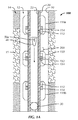
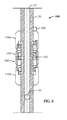
- Figure 1A illustrates a tubing string or drill pipe 20 having an electronically-actuated, multi-set straddle apparatus 100 according to the present disclosure in a run-in condition.
- the apparatus 100 includes straddle packers 110a-b disposed on each side of a flow port unit 150.
- the packers 110a-b and flow port unit 150 can be separate components with housings (not shown) coupled together on the tubing string 20, or they can be an integrated assembly coupled to the tubing string 20.
- the apparatus 100 For run-in of the tubing string 20 into a borehole 10, the apparatus 100 is lowered with the tubing string 20 to a desired zone 15 in the formation 14 to be treated with fracture treatment or other known type of treatment, such as acidizing, fracture acidizing, carbonate treatment, acid treatment, solvent treatment, chemical treatment, matrix treatment, etc.
- fracture treatment or other known type of treatment such as acidizing, fracture acidizing, carbonate treatment, acid treatment, solvent treatment, chemical treatment, matrix treatment, etc.
- the packers 110a-b of the apparatus 100 are unset and can be in the open position, and the flow port unit 150 can be closed.
- packer valves 114 on the packers 110a-b can keep internal ports 112 opened, and a flow valve 154 on the flow port unit 150 can remain closed relative to an internal port 152.
- the packer valves 114 can be closed to prevent inadvertent setting.
- an isolation valve 30 Downhole of the apparatus 100, an isolation valve 30 can be opened during run-in. Once the apparatus 100 is in position, operators close the isolation valve 30 using any of a number of techniques. For example, operators can deploy a plug 40 (e.g., dart, ball, etc.) down the tubing string 20 to land in a seat of the isolation valve 30 below the bottom packer 110b. With the plug 40 seated, pressure applied down the tubing string or drill pipe 20 can be used to set the packers 110a-b.
- a plug 40 e.g., dart, ball, etc.
- any other suitable type of tubing closure can be used.
- closing off fluid communication in the isolation valve 30 can use techniques other than a dropped plug 40, which would need to be floated so the apparatus 100 can be moved to another zone. As expected, floating a dropped plug 40 may not be possible after fracture stimulation because proppant can fill portion of the apparatus 100 on top of the plug 40. Accordingly, other techniques can be used to control the opening and closing of the isolation valve 30.
- the isolation valve 30 can be activated with any number of techniques-e.g., RFID tags in the flow stream may be used alone or with plugs; chemicals and/or radioactive tracers may be used in the flow stream; mud pressure pulses (if the system is closed chamber); mud pulses (if the system is actively flowing); etc.
- the isolation valve 30 can have a radio frequency identification (RFID) reader, battery, and electronics and can open and close in response to passage of at least one RFID tag.
- RFID radio frequency identification
- the controller 200 can be configured to receive mud pulses from the surface or may include an electromagnetic (EM) or an acoustic telemetry system, which includes a receiver or a transceiver (not shown).
- EM electromagnetic
- acoustic telemetry system which includes a receiver or a transceiver (not shown).
- the isolation valve 30 can have other types of detectors or sensors, such as a pressure sensor, telemetry sensor, a Hall Effect sensor, a radioactive trace detector, a chemical detector, and the like.
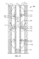
- FIG. 1B which shows the disclosed straddle apparatus 100 during part of the setting procedure of the packers 110a-b
- fluid flow down the tubing string's bore 22 does not pass the closed isolation valve 30. Therefore, the fluid flows out the fill ports 112 and sets (e.g., inflates or compresses) the packers 110a-b to engage the surrounding borehole 10. This isolates the portion of the borehole annulus 12 between the packers 110a-b.
- the packers 110a-b do not set until a certain desired pressure is reached to prevent premature setting during circulation when running in the hole.
- each of the packers 110a-b may have its own fill ports 112, although this is not strictly necessary. Instead, the packers 110a-b can share one or more common fill ports 112 with adequate routing of flow in the apparatus 100 using techniques known in the art.
- the plug 40 when deployed as in Figure 1A can have a first tag 50a that passes one or more control units 200 downhole as the plug 40 is dropped from surface down the tubing string or drill pipe 20.
- the tag 50a can be conveyed alone or in another way. Either way, the tag 50a can be a Radio Frequency Identification (RFID) tag, although other types of devices and techniques can be used.
- RFID Radio Frequency Identification
- a plug 40 is not used (e.g., if the isolation valve 30 is RFID activated), then the tag 50a may be conveyed downhole all the same without the plug 40, but can be conveyed with some other object if necessary.
- the one or more control units 200 on the apparatus 100 use RFID technology to manipulate sleeves, valves, ports, or the like on the apparatus 100 to set and unset the packers 110a-b and to open and close the flow port unit 150 according to the procedures disclosed herein. To do this, the one or more control units 200 detect the tag 50a when it reaches the apparatus 100. In actuality, multiple tags 50a may be deployed for redundancy, with only one required to be detected to activate the apparatus 100.
- the one or more control units 200 on the apparatus 100 can open the packer valves 114 (if not already open) can then initiate a timer or delay before closing the fill ports 112 for the packers 110a-b and opening the flow port unit 150.
- the delay can be about 30-minutes or other amount of time sufficient so the pressure applied downhole can set (e.g., inflate or compress) the packers 110a-b as in Figure 1B to a certain pressure given the hole size and casing ID.
- the one or more control units 200 then electronically activate the packer valves 114 to close the fill ports 112 for the packers 110a-b and electronically activate the flow valve 154 to open the flow port unit 150 so treatment can be applied in the isolated portion of the annulus 12.
- Figure 1C shows the disclosed straddle apparatus 100 during this set condition.
- the valves 114 on the packers 110a-b are moved by the one or more control units 200 to close the internal ports 112.
- one or more pumps of the one or more control units 200 turn on and push spring loaded sleeves to lock in element pressure for the packers 110a-b.
- the sleeves close off the ports 112 to prevent further pressure from entering the element of the packers 110a-b and to trap setting pressure in the packers' setting mechanisms.
- the one or more control units 200 open the flow valve 154 on the flow port unit 150 so that flow down the tubing string's bore 22 can flow out the flow ports 152 and treat the formation zone 15 between the set packers 110a-b.
- the flow valve 154 on the flow port unit 150 can also open in the same fashion as the packers 110a-b- e.g. , utilizing pump(s) to shift a spring loaded sleeve. This activation on the flow unit 150 can also be delayed a certain amount of time after closing the packers' fill ports 112 to ensure that the setting and closing of the packers 110a-b is completed.
- treatment fluid such as fracture proppant, acid, etc.
- treatment fluid can be pumped into the straddled area between the two packers 110a-b.
- operators deploy another tag 50b down the tubing string 20 in the fluid flow.
- the one or more control units 200 on the apparatus 100 detect the second tag 50b when it reaches the apparatus 100 and electronically deactivate the packers 110a-b and close the flow port unit 150.
- the operations initiated by this tag 50b may also be on a time delay.
- the packers 110a-b may be opened to unset (e.g., deflate or uncompress) a certain period of time before the flow port unit 150 is opened.
- eventual unsetting of the packers 110a-b and closing of the flow port unit 150 may also be timed based on passage of the first tag 50a. In this case, deploying the second tag 50b may be unnecessary to revert the apparatus 100 to its run-in condition.
- use of a second tag 50b allows for independent deactivation of the apparatus 100 when desired, and may even be used as a backup if a timed operation fails.
- the one or more control units 200 may be able to respond to other forms of communication similar to the details provided above with reference to the isolation valve 30. Accordingly, the one or more control units 200 can be activated with any number of techniques-e.g., RFID tags in the flow stream may be used alone or with plugs; chemicals and/or radioactive tracers may be used in the flow stream; mud pressure pulses (if the system is closed chamber); mud pulses (if the system is actively flowing); etc. These other forms of activation may be used as an alternative or as a backup to an RFID system as disclosed herein. In this way, opening and closing the packer valves 114 and flow valve 154 can use pressure pulses, telemetry, or any other disclosed technique, in addition to or as an alternative to the RFID system disclosed herein.
- RFID tags in the flow stream may be used alone or with plugs; chemicals and/or radioactive tracers may be used in the flow stream; mud pressure pulses (if the system is closed chamber); mud pulses (if the system is actively flowing); etc.
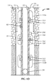
- Figure 1D illustrates the tubing string 20 with the disclosed straddle apparatus 100 in an unset condition.
- the ports 112 of the packers 110a-b can be opened so the elements can unset (e.g., deflate or uncompress) and disengage from the borehole 10.
- the flow port unit 150 closes.
- the isolation valve 30 can be opened using any of the various techniques disclosed herein. For example, the previously landed plug (40), if used, can be reverse circulated out of the valve 30 and floated to the surface.
- the tubing string 20 can be moved in the borehole 10 to position the apparatus 100 near another downhole zone to be treated.
- valves (60: Fig. 1 D) to selectively equalize pressure of the packed-off zone with the annulus prior to unsetting the packers 110a-b.
- These valves (60) can be actuated using any of the available techniques as disclosed herein and may be controlled by the one or more controllers 200. When opened, the isolated pressure between the set packers 110a-b is equalized with the annulus pressure above and/or below the packers 110a-b to facilitate unsetting the packers 110a-b.
- operations can start by having the packer valves 114 initially open. This might not be desired in some instance. While running-in or moving between zones, the apparatus 100 may get stuck by material in the annulus. If this occurs, then it is normal to circulate fluid in order to dislodge the apparatus 100. Any pack-off occurring around the apparatus 100 can inhibit this circulation, and a differential pressure can build up that may start to set the packers 110a-b. Therefore, it may be desirable to only expose the packers 110a-b to pressure when they are going to be set.
- the one or more controllers 200 of the apparatus 100 can close the packers 110a-b when the apparatus 100 is being run-in and moved in the borehole, and the one or more controllers 200 can open the packers 110a-b when it is desirable to expose the packers 110a-b to pressure.
- the packer valves 114 may remain open during various stages of the operation, and the packer's setting mechanisms can be protected by additional valve mechanisms.
- U.S. Pat. 7,836,962 which is incorporated herein by reference, discloses a pressure control valve mechanism that can limit the exposure of a packer's setting mechanism on the apparatus 100 to particular pressures.
- the packers 110a-b can have a separate piston assembly that is operable to control fluid communication between the fill ports 112 and the packers' setting mechanisms by closing off fluid communication therethrough above and/or below a certain pressure level.
- one or both of the packers 110a-b can be an inflatable packer having an inflatable element that inflates with the pressure communicated down the tubing 20.
- one or both of the packers 110a-b can be a resettable compression-set packer having a compressible element that is compressed with the pressure communicated down the tubing.
- FIGS 2A-1 and 2A-2 illustrate components of a packer 110 of the disclosed straddle apparatus (100) as an inflatable packer in unset and set conditions, respectively.
- the inflatable packer 110 includes a valve unit 120 disposed on a mandrel 116, which couples to or is part of the tubing string (20).
- a valve, piston, or sleeve 130 is movably disposed in a chamber 122 of the valve unit 120 between a closed condition ( Fig. 2A-1 ) and an opened condition ( Fig. 2A-2 ) relative to one or more internal ports 112 in the mandrel 116.
- the valve 130 has the form of a cylindrical sleeve disposed concentrically on the mandrel 116 so multiple ports 112 can be isolated around the circumference of the mandrel 116.
- the sleeve 130 forms the internal valve 114 of the packer 110 described previously.
- Seals 134 (only some of which are shown) on the sleeve 130 can seal off the internal ports 112.
- the sleeve 130 is biased in the chamber 122 to the opened condition ( Fig. 2A-1 ) by a biasing element 132, such as a spring or the like.
- a biasing element 132 such as a spring or the like.
- force, pressure, or other counter bias from the one or more control units 200 moves the sleeve 130 against the bias of the biasing element 112 to close the sleeve 130 over the internal ports 112.
- the biasing element 132 moves the sleeve 130 open so that flow of fluid can pass through the internal ports 112.
- the flow through the ports 112 can pass through a bypass channel 124 and fill a chamber 142 of an inflatable packer element 140.
- a separate piston assembly (not shown), as noted above, can be provided at such a bypass channel 124 to control fluid communication from the mandrel's port 112 to the packing mechanism (but not necessarily to control reverse communication) by closing off fluid communication therethrough above and/or below a certain pressure level.
- the packing mechanism e.g., 140, 142, etc.
- the packing mechanism can be prevented from prematurely setting at a low pressure level and/or being over-exposed to high pressure levels during treatment.
- the pressure from the filling fluid extends the inflatable element 140 to engage a surrounding borehole wall as noted herein. Details related to the filing and operation of an inflatable element on a packer are generally know so that they are not repeated here. Accordingly, various components related to the inflatable element 140 are omitted.
- the internal ports 112 of the packer 110 can include features to filter flow therethrough so proppant and other particulates do not enter components of the packer 110.
- the ports 112 can use sets of slots dimensioned with respect to the particulate size expected in the operational fluid.
- the ports 112 can use screens or other types of particulate filtering mediums.
- Figures 2B-1 and 2B-2 illustrate components of a packer 110 of the disclosed straddle apparatus (100) as a compression-set packer in unset and set conditions, respectively.
- the packer 110 includes a valve unit 120 disposed on a mandrel 116, which couples to or is part of the tubing string (20).
- a valve, piston, or sleeve 130 is movably disposed in a chamber 122 of the valve unit 120 between a closed condition ( Fig. 2B-1 ) and an opened condition ( Fig. 2B-2 ) relative to one or more internal ports 112 in the mandrel 116.
- the valve 130 has the form of a cylindrical sleeve disposed concentrically on the mandrel 116 so multiple ports 112 can be isolated around the circumference of the mandrel 116.
- the sleeve 130 forms the internal valve 114 of the packer 110 described previously.
- Seals 134 (only some of which are shown) on the sleeve 130 seal off the internal ports 112.
- the sleeve 130 is biased in the chamber 122 to the opened condition ( Fig. 2B-1 ) by a biasing element 132, such as a spring or the like.
- a biasing element 132 such as a spring or the like.
- pressure or other counter bias from the one or more control units 200 moves the sleeve 130 against the bias of the biasing element 112 to close the sleeve 130 over the internal ports 112.
- the biasing element 132 moves the sleeve 130 open so that flow of fluid can pass through the internal ports 112.
- the flow through the ports 112 can pass through a bypass channel 124 and fill a chamber 144 of a piston element 146.
- a separate piston assembly (not shown), as noted above, can be provided at such a bypass channel 124 to control fluid communication between the mandrel's port 112 and the packing mechanism (but not necessarily to control reverse communication) by closing off fluid communication therethrough above and/or below a certain pressure level.
- the packing mechanism e.g., 144, 146, 148, etc.
- the packing mechanism can be prevented from prematurely setting at a low pressure level and/or being over-exposed to high pressure levels during treatment.
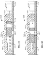
- FIGS 3A-3B illustrate components of a flow port unit 150 of the disclosed straddle apparatus (100) in closed and opened conditions, respectively.
- the flow port unit 150 includes a valve unit 160 disposed on a mandrel 156, which can be coupled to or part of the tubing string (20).
- a valve, piston, or sleeve 170 is movably disposed in a chamber 162 of the valve unit 160 between a closed condition ( Fig. 3A ) and an opened condition ( Fig. 3B ) relative to one or more internal ports 152 in the mandrel 156.
- valve 170 has the form of a cylindrical sleeve disposed concentrically on the mandrel 156 so multiple ports 152 can be isolated around the circumference of the mandrel 156. As such, the sleeve 170 forms the internal valve 154 of the flow port unit 150 described previously.
- seals 174 (only some of which are shown) on the sleeve 170 seal off the internal ports 152.
- the sleeve 170 is biased in the chamber 162 to the closed condition ( Fig. 3A ) by a biasing element 172, such as a spring or the like.
- a biasing element 172 such as a spring or the like.
- pressure or other counter bias from the one or more control units 200 moves the sleeve 170 against the bias of the biasing element 172 to open the sleeve 170 relative to the internal ports 152.
- the biasing element 172 moves the sleeve 170 closed so that flow of fluid cannot pass through the internal ports 152 and out external ports 164 on the valve unit 160.
- the internal port 152 of the flow port unit 150 can include features to resist erosion or corrosion caused by flow of treatment fluid.
- deactivation of the force, pressure, or counter bias from the one or more control units 200 allows the biasing element 172 to move the sleeve 170 closed so fluid can then be prevented from flowing out of the flow port unit 150.
- the concentrically arranged sleeves 130 and 170 and mandrels 116 and 156 in Figures 2A-1 to 3B are used to facilitate assembly of the apparatus 100 and to accommodate the cylindrical arrangement and multiple ports 112 and 152.
- the apparatus 100 can have the valves 120 and 140 in different configurations, such as pistons or rods.
- each port 112 and 152 can have its own valve 130 and 170.
- the apparatus 100 may have one or more control units 200 for activating the packers 110a-b and flow port unit 150.
- each of the components 110a-b and 150 can have its own control unit 200, or a single control unit 200 can be used for all of the components 110a-b and 150.
- the packers 110a-b may share a control unit 200, while the flow port unit 150 may have its own control unit 200.
- the one or more control units 200 can include components as schematically illustrated in Figure 4 .
- the control unit 200 includes a controller 202, which can include any suitable processor for a downhole tool.
- the controller 202 is operatively coupled to a sensor or reader 204 and to an actuator 206.
- the type of sensor or reader 204 used depends on how commands are conveyed to the control unit 200 while deployed downhole.
- Various types of sensors, readers 202, or the like can be used, including, but not limited to, a radio frequency identification (RFID) reader, sensor, or antenna; a Hall Effect sensor; a pressure sensor; a telemetry sensor; a radioactive trace detector; a chemical detector; and the like.
- RFID radio frequency identification
- the control unit 200 can be activated with any number of techniques- e.g. , RFID tags in the flow stream may be used alone or with plugs; chemicals and/or radioactive tracers may be used in the flow stream; mud pressure pulses (if the system is closed chamber, e.g. cement bridges off in the annular area between the casing OD and borehole ID); mud pulses (if the system is actively flowing); etc.
- control unit 200 can be configured to receive mud pulses from the surface or may include an electromagnetic (EM) or an acoustic telemetry system, which includes a receiver or a transceiver (not shown).
- EM electromagnetic
- acoustic telemetry system which includes a receiver or a transceiver (not shown).
- An example of an EM telemetry system is discussed in U.S. Pat. No. 6,736,210 , which is hereby incorporated by reference in its entirety.
- the control unit 200 and the sensor 202 will be to an RFID based system, which may be preferred in some instances.
- the sensor 202 can be an RFID reader that uses radio waves to receive information (e.g., data and commands) from one or more electronic RFID tags 50, which can be attached to a plug or other object. The information is stored electronically, and the RFID tags 50 can be read at a distance from the reader 202.
- the RFID tags 50 are inserted into the tubing (20) at surface level and are carried downhole in the fluid stream.
- the electronic reader 202 on the tool's control unit 200 interprets instructions embedded in the tags 50 to perform a required operation.
- Logic of the controller 202 can count triggers, such as the passage of a particular RFID tag 50, a number of RFID tags 50, or the like.
- the logic of the controller 202 can use timers to actuate the actuators 206 after a period of time has passed since a detected trigger (e.g., after passage of an RFID tag 50 or after a previous operation is completed). These and other logical controls can be used by the controller 202.
- the controller 202 When a particular instruction is detected, for example, the controller 202 operates a switch 206 or the like, to supply power from a power source 208 to one or more actuators 210, which can include one or more motors, pumps, solenoids, or other devices to provide force, pressure, or counter bias to the pistons, valves, or sleeves 130, 170 of the apparatus 100.
- the power source 208 can be a battery deployed downhole with the unit 200.
- the actuators 210 in the form of motors can be operatively coupled to the valves, pistons, or sleeves 130, 170 of the apparatus 100 with gears and the like. When activated, the motor actuators 210 can move the valves, pistons, or sleeves 130, 170 open and close as disclosed herein.
- the actuators 210 in the form of pump(s) or solenoid(s) can be operatively coupled between pressure source(s) or reservoir(s) 212 and the valves, pistons, or sleeves 130, 170 of the apparatus 100.
- the pressure source or reservoir 212 can be a reservoir of high pressure fluid.
- the solenoid actuators 210 can be activated by the power to open and allow the high pressure fluid to act on the valves, pistons, or sleeves 130, 170.
- the pressure source(s) or reservoir(s) 212 may be a reservoir of hydraulic fluid.
- the pump actuators 210 can be activated by the power to pump the hydraulic fluid of the source 212 to apply pressure against the valves, pistons, or sleeves 130, 170. Additionally, the pump actuators 210 can be operated in the reverse to relieve pressure against the valves, pistons, or sleeves 130, 170.
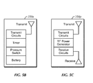
- FIG. 5A illustrates a radio-frequency identification (RFID) electronics package 300 for the control unit 200.
- RFID radio-frequency identification
- the electronics package 300 may communicate with an active RFID tag 350a
- the active RFID tag 350a ( Fig. 5B ) includes a battery, pressure switch, timer, and transmit circuits.
- the passive RFID tag 350p ( Fig. 5C ) includes receive circuits, RF power generator, and transmit circuits.
- either of the RFID tags 350a-p may be individually encased and dropped or pumped through the tubing string as noted herein.
- either of the RFID tags 350a-p may be embedded in a ball (not shown) for seating in a ball seat of a tool, a plug, a bar, or some other device used to initiate action of a downhole tool.
- the RFID electronics package 300 includes a receiver 302, an amplifier 304, a filter and detector 306, a transceiver 308, a microprocessor 310, a pressure sensor 312, a battery pack 314, a transmitter 316, an RF switch 318, a pressure switch 320, and an RF field generator 322.
- Some of these components e.g. , microprocessor 310 and battery 314) can be shared with the other components of the control unit 200 described herein.
- the pressure switch 320 closes once the port apparatus 100 is deployed to a sufficient depth in the wellbore.
- the pressure switch 320 may remain open at the surface to prevent the electronics package 300 from becoming an ignition source.
- the microprocessor 310 may also detect deployment in the wellbore using the pressure sensor 312. Either way, the microprocessor 310 may delay activation of the transmitter 316 for a predetermined period of time to conserve the battery pack 314.
- the microprocessor 310 can begin transmitting a signal and listening for a response. Once a passive tag 350p is deployed into proximity of the transmitter 316, the passive tag 350p receives the transmitted signal, converts the signal to electricity, and transmits a response signal. In turn, the electronics package 300 receives the response signal via the antenna 302 and then amplifies, filters, demodulates, and analyzes the signal. If the signal matches a predetermined instruction signal, then the microprocessor 310 may activate an appropriate function on the apparatus 100, such as energizing a pump, starting a timer, etc.
- the instruction signal carried by the tag 350a-p may include an address of a tool (if the tool string includes multiple tools, packers, sleeves, valves, etc.), a set position (if the apparatus 100 is adjustable), a command or operation to perform, and other necessary information.
- the transmission components 316-322 may be omitted from the electronics package 300.
- the active tag 350a can include its own battery, pressure switch, and timer so that the tag 350a may perform the function of the components 316-322.
- either of the tags 350a-p can include a memory unit (not shown) so that the microprocessor 310 can send a signal to the tag 350a-p and the tag 350a-p can record the data, which can then be read at the surface. In this way, the recorded data can confirm that a previous action has been carried out.
- the data written to the RFID tag 350a-p may include a date/time stamp, a set position (the command), a measured position (of control module position piston), and a tool address.
- the written RFID tag 350a-p may be circulated to the surface via the annulus.
- the microprocessor 310 can control operation of the other control unit components disclosed herein, such as discussed previously with reference to Figure 4 .
- Figure 6 schematically shows how the disclosed apparatus 100 can have integrated components.
- the apparatus 100 has first and second packers 110a-b and a flow unit 150 disposed on the apparatus 100.
- the flow unit 150 is disposed between the first and second packers 110a-b, which can be inflatable or compression-set packers as disclosed herein.
- the apparatus 100 has at least one port 182, which is in fluid communication with the tubing 20 and which can be selectively communicated with the packers 110a-b and the flow unit 150.
- At least one valve 180 placed in one condition can communicate the tubing 20 with the packers 110a-b through the at least one port 182, while the flow unit 150 is closed.
- the at least one valve 180 placed in another condition can communicate the tubing 20 with the borehole (not shown) through the at least one port 182, while the packers 110a-b are closed.
- the at least one valve 180 including the control unit 200 is electronically operable to open and close fluid communication between the tubing 20 and the first and second packers 110a-b or the borehole through the at least one port 182.
Abstract
Description
- Inflatable production packers are inflated by opening a spring-compressed poppet valve that allows fluid to inflate the packer element. When the preferred pressure is reached, the poppet valve closes and traps the inflation pressure within the element. Deflating the element depends on the particular mechanical design of the packer. For example, the packer may use a rotate-release system in which the workstring is pulled up and rotated to deflate the element. In contrast, a pull-release system requires the workstring to be pulled up with an appropriate force to shear releasing pins so the element can be deflated.
- A straddle packer injection tool has inflatable straddle packers to isolate a section of a borehole downhole so fluid treatment can be applied. This tool requires manipulation of the tubing/drill pipe to function-i.e., to inflate the packing elements, lock in the element pressure, open frac ports, close the frac ports, and deflate the elements. When the tool is to be set multiple times downhole, the tool needs to revert back to an initial condition so it can be set again. As expected, functioning this tool multiple times downhole can be challenging.
- The subject matter of the present disclosure is directed to overcoming, or at least reducing the effects of, one or more of the problems set forth above.
- A straddle fluid treatment apparatus deploys in a borehole with tubing to treat sections of the borehole with fracture treatment or other type of treatment. The apparatus has first and second packers disposed on the apparatus. Each of the packers can have a fill port in fluid communication with the tubing and can have a packer valve biased to open fluid communication between the packers and the fill port. Disposed between the first and second packers, the apparatus has a flow unit having a flow port in fluid communication with the tubing, and a flow valve of the flow unit is biased to close fluid communication between the flow port and the borehole.
- Finally, one or more control units on the apparatus are operatively coupled to the packer valves and the flow valves. The control units operate the valves based on at least one detected activation with instructions conveyed downhole to the apparatus. For example, an RFID system can be used to send and receive instructions via RFID tag(s) to the one or more control units to configure operation of the apparatus.
- During run-in, the packer valves can be open, and the flow valve can be closed. Once the apparatus reaches a section of the borehole to be treated, fluid flow through the tubing string beyond the lowermost packer is closed off. For example, an isolation valve on the tubing string is closed by any of a number of techniques, such as by a plug dropped to close off the valve or by other methods. The packer valves are then opened (if not already), and pressure pumped down the tubing string enters the packers through the open packer valves to set the packers and seal off the section of the borehole.
- In one embodiment, one or both of the packers are inflatable packers having an inflatable packer element that inflates with the pressure communicated down the tubing. In another embodiment, one or both of the packers are compressible packers having a compressible packer element that is compressed with the pressure communicated down the tubing.
- Eventually, the one or more control units electronically activate the packer valves to close fluid communication between the packers and the fill ports so that the pressure is trapped in the packers' setting mechanisms. For example, pressure can be trapped in an inflatable element of an inflatable packer, or pressure can be trapped in a piston chamber of a compressible packer. In one implementation, this activation can occur after a set period of time after passage of an initial RFID tag, which may be associated with a plug dropped to close off the tubing string or associated with some other action.
- Meanwhile, the one or more control units electronically activate the flow valve to open fluid communication between the flow port and the borehole. This may also be timed after passage of the initial RFID tag. At this point, treatment pumped down the tubing string can flow out the open flow port and into the isolated borehole section to treat the formation or the like.
- Eventually, the flow port can be closed, and the packer valves can be opened to unset the packers (e.g., deflate the inflatable packers or release the pistons of the compressible packers). These operations can be initiated in a number of ways. In one example, the closing of the flow valve and the reopening of the packer valves can be timed to a set period of time after the passage of the initial RFID tag. Alternatively, a new RFID tag can be deployed down the tubing string in the flow used during the treatment through the flow port. This new RFID tag can be detected by the one or more control units on the apparatus to initiate closing of the flow valve and opening of the packer valves.
- Still further, activation of this second stage can use another type of system different than the RFID system used with the initial RFID tag. In this case, the one or more control units on the apparatus may have multiple means for receiving instructions. In the end, circulation through the tubing string may be restored by opening the downhole isolation valve (e.g., the previously dropped plug can be floated to the surface, the valve can be electronically activated, or some other operation can be performed) to reopen flow through tubing string. With the isolation valve opened, the tubing string can be moved to a new section of the borehole so isolation, pack-off, and treatment can be repeated.
- An example of a straddle fluid treatment apparatus deployed in a borehole with tubing comprises:
- first and second packers disposed on the apparatus;
- a flow unit disposed on the apparatus between the first and second packers; and
- at least one valve unit disposed on the apparatus and detecting at least one activation, the at least one valve unit being electronically operable in response to the at least one detected activation to open and close fluid communication between the tubing and the first and second packers and being electronically operable in response to the at least one detected activation to open and close fluid communication between the tubing and the borehole through the flow unit.
- The at least one valve unit may comprise:
- a packer valve in fluid communication between the tubing and at least one of the first and second packers, the packer valve being biased to an opened condition and being electronically operable in response to the at least one detected activation to a closed condition, the packer valve in the opened condition permitting fluid communication between the tubing and the at least one packer, the packer valve in the closed condition preventing fluid communication therebetween.
- The packer valve may comprise:
- a sleeve disposed in the packer valve and biased to the opened condition relative to at least one fill port in fluid communication with the tubing, the sleeve in the opened condition permitting fluid communication between the at least one fill port and the at least one packer; and
- an actuator in communication with the sleeve and being electronically operable in response to the at least one detected activation to move the sleeve to the closed condition relative to the at least one fill port.
- The at least one packer may comprise an inflatable packer element being inflatable with fluid pressure communicated from the at least one fill port.
- The at least one packer may comprise a compressible packer element being compressible with fluid pressure communicated from the at least one fill port.
- The actuator may comprise a pump operable to pump fluid pressure against the bias of the sleeve.
- The sleeve may comprise a biasing member biasing the sleeve to the opened condition.
- The at least one valve unit may comprise:
- a flow valve in fluid communication between the tubing and the borehole, the flow valve being biased to a closed condition and being electronically operable in response to the at least one detected activation to an opened condition, the flow valve in the opened condition permitting fluid communication between the tubing and the borehole, the flow valve in the closed condition preventing fluid communication therebetween. The flow valve may be electronically operable to the open condition after a preset time past the at least one detected activation.
- The flow valve may comprise:
- a sleeve disposed in the flow valve and biased to the closed condition relative to at least one flow port in fluid communication with the tubing, the sleeve in the closed condition preventing fluid communication between the at least one flow port and the borehole; and
- an actuator in communication with the sleeve and being electronically operable in response to the at least one detected activation to move the sleeve to the opened condition relative to the at least one flow port.
- The actuator may comprise a pump operable to pump fluid pressure relative to the bias of the sleeve.
- The sleeve may comprise a biasing member biasing the sleeve to the closed condition.
- The biasing member may comprise a spring.
- The sleeve may comprise at least one slot moving between a misaligned condition and an aligned condition with respect to the at least one flow port with the movement of the sleeve between the closed position and the opened position.
- The at least one valve unit may comprise:
- a reader detecting a radio frequency identification tag as the at least one detected activation; and
- an actuator operatively coupled to the reader and actuating the at least one valve unit in response to the detection of the radio frequency identification tag.
- The actuator may comprise a pump operable to pump fluid pressure relative to bias of the at least one valve unit.
- The at least one valve unit may comprise a sensor responsive to a signal as the at least one detected activation.
- The sensor may comprise a reader responsive to passage of at least one radio frequency identification tag.
- Another example of a straddle fluid treatment apparatus deployed in a borehole with tubing, the apparatus comprises:
- first and second packers disposed on the apparatus and having
- at least one fill port in fluid communication with the tubing, and
- at least one packer valve biased to open fluid communication between the at least one fill port and the first and second packers;
- a flow unit disposed on the apparatus between the first and second packers and having
- a flow port in fluid communication with the tubing, and
- a flow valve biased to close fluid communication between the flow port and the borehole; and
- one or more control units operatively coupled to the at least one packer valve and the flow valve and detecting at least one activation, the one or more control units electronically activating the at least one packer valve in response to the at least one detected activation to close fluid communication between the first and second packers and the at least one fill port, the one or more control units electronically activating the flow valve in response to the at least one detected activation to open fluid communication between the flow port and the borehole. A method of treating sections of a borehole may comprise:
- deploying an apparatus on tubing to one of the sections of the borehole;
- setting first and second packers of the apparatus against the borehole by pumping fluid pressure down the tubing and through at least one packer valve opened on the apparatus;
- trapping the fluid pressure in the first and second packers by electronically closing the at least one packer valve;
- electronically opening at least one flow valve disposed on the apparatus between the first and second packers; and
- pumping treatment from the tubing to the section of the borehole through the open flow valve.Setting the first and second packers may comprise closing off fluid communication in the tubing downhole of the apparatus.
- Electronically closing the at least one packer valve may comprise detecting at least one activation and electronically initiating the closing of the at least one packer valve in response to the at least one detected activation. Detecting the at least one activation may comprise detecting passage of a radio frequency identification tag relative to at least one radio frequency identification reader on the apparatus. Electronically initiating the closing of the at least one packer valve may further comprise initiating after a period of time past the detected passage of the radio frequency identification tag.Electronically opening the at least one flow valve disposed on the apparatus between the first and second packers may comprise initiating the opening of the at least one flow valve after a period of time past the detected passage of the radio frequency identification tag. The method may further comprise electronically closing the at least one flow valve. The method may further comprise unsetting the first and second packers by electronically opening the at least one packer valve. The method may further comprise deploying the apparatus on the tubing to another of the sections of the borehole.
- Electronically closing the at least one flow valve may comprise detecting at least one activation and electronically initiating the closing of the at least one flow valve in response to the at least one detected activation.Electronically initiating the closing of the at least one flow valve in response to the at least one detected activation may comprise detecting passage of a radio frequency identification tag relative to at least one radio frequency identification reader on the apparatus. Electronically initiating the closing of the at least one flow valve may further comprise initiating after a period of time past the at least one detected activation.
- The foregoing summary is not intended to summarize each potential embodiment or every aspect of the present disclosure.
-
-
Fig. 1A illustrates a tubing string having an electronically-actuated, multi-set straddle apparatus according to the present disclosure in a run-in condition. -
Fig. 1B illustrates the tubing string with the disclosed straddle apparatus in a partial set condition. -
Fig. 1C illustrates the tubing string with the disclosed straddle apparatus in a set condition -
Fig. 1D illustrates the tubing string with the disclosed straddle apparatus in an unset condition. -
Figs. 2A-1 and 2A-2 illustrate components of an inflatable packer for the disclosed straddle apparatus in unset and set conditions, respectively. -
Fig. 2B-1 and 2B-2 illustrate components of a compression-set packer for the disclosed straddle apparatus in unset and set conditions, respectively. -
Fig. 3A illustrates components of a flow port unit for the disclosed straddle apparatus in a closed condition. -
Fig. 3B illustrates components of the flow port unit for the disclosed straddle apparatus in an opened condition. -
Fig. 4 schematically illustrates an electronic system having a controller for the disclosed straddle apparatus. -
Fig. 5A illustrates an embodiment of a radio-frequency identification (RFID) electronics package for the disclosed controller. -
Figs. 5B-5C illustrate an active RFID tag and a passive RFID tag, respectively. -
Fig. 6 schematically shows how the disclosed straddle apparatus can have integrated components. -
Figure 1A illustrates a tubing string ordrill pipe 20 having an electronically-actuated,multi-set straddle apparatus 100 according to the present disclosure in a run-in condition. Theapparatus 100 includesstraddle packers 110a-b disposed on each side of aflow port unit 150. Thepackers 110a-b and flowport unit 150 can be separate components with housings (not shown) coupled together on thetubing string 20, or they can be an integrated assembly coupled to thetubing string 20. - For run-in of the
tubing string 20 into aborehole 10, theapparatus 100 is lowered with thetubing string 20 to a desiredzone 15 in theformation 14 to be treated with fracture treatment or other known type of treatment, such as acidizing, fracture acidizing, carbonate treatment, acid treatment, solvent treatment, chemical treatment, matrix treatment, etc. During run-in theborehole 10, thepackers 110a-b of theapparatus 100 are unset and can be in the open position, and theflow port unit 150 can be closed. In particular,packer valves 114 on thepackers 110a-b can keepinternal ports 112 opened, and aflow valve 154 on theflow port unit 150 can remain closed relative to aninternal port 152. Alternatively, thepacker valves 114 can be closed to prevent inadvertent setting. - Downhole of the
apparatus 100, anisolation valve 30 can be opened during run-in. Once theapparatus 100 is in position, operators close theisolation valve 30 using any of a number of techniques. For example, operators can deploy a plug 40 (e.g., dart, ball, etc.) down thetubing string 20 to land in a seat of theisolation valve 30 below thebottom packer 110b. With theplug 40 seated, pressure applied down the tubing string ordrill pipe 20 can be used to set thepackers 110a-b. - Rather than an
isolation valve 30, any other suitable type of tubing closure can be used. Moreover, closing off fluid communication in theisolation valve 30 can use techniques other than adropped plug 40, which would need to be floated so theapparatus 100 can be moved to another zone. As expected, floating adropped plug 40 may not be possible after fracture stimulation because proppant can fill portion of theapparatus 100 on top of theplug 40. Accordingly, other techniques can be used to control the opening and closing of theisolation valve 30. - In particular, the
isolation valve 30 can be activated with any number of techniques-e.g., RFID tags in the flow stream may be used alone or with plugs; chemicals and/or radioactive tracers may be used in the flow stream; mud pressure pulses (if the system is closed chamber); mud pulses (if the system is actively flowing); etc. For example, theisolation valve 30 can have a radio frequency identification (RFID) reader, battery, and electronics and can open and close in response to passage of at least one RFID tag. As an alternative to RFID, for example, thecontroller 200 can be configured to receive mud pulses from the surface or may include an electromagnetic (EM) or an acoustic telemetry system, which includes a receiver or a transceiver (not shown). An example of an EM telemetry system is discussed inU.S. Pat. No. 6,736,210 , which is hereby incorporated by reference in its entirety. In general, theisolation valve 30 can have other types of detectors or sensors, such as a pressure sensor, telemetry sensor, a Hall Effect sensor, a radioactive trace detector, a chemical detector, and the like. - Turning to
Figure 1B , which shows the disclosedstraddle apparatus 100 during part of the setting procedure of thepackers 110a-b, fluid flow down the tubing string'sbore 22 does not pass theclosed isolation valve 30. Therefore, the fluid flows out thefill ports 112 and sets (e.g., inflates or compresses) thepackers 110a-b to engage the surroundingborehole 10. This isolates the portion of theborehole annulus 12 between thepackers 110a-b. Preferably, thepackers 110a-b do not set until a certain desired pressure is reached to prevent premature setting during circulation when running in the hole. As further shown, each of thepackers 110a-b may have itsown fill ports 112, although this is not strictly necessary. Instead, thepackers 110a-b can share one or morecommon fill ports 112 with adequate routing of flow in theapparatus 100 using techniques known in the art. - The
plug 40 when deployed as inFigure 1A can have afirst tag 50a that passes one ormore control units 200 downhole as theplug 40 is dropped from surface down the tubing string ordrill pipe 20. Alternatively, thetag 50a can be conveyed alone or in another way. Either way, thetag 50a can be a Radio Frequency Identification (RFID) tag, although other types of devices and techniques can be used. If aplug 40 is not used (e.g., if theisolation valve 30 is RFID activated), then thetag 50a may be conveyed downhole all the same without theplug 40, but can be conveyed with some other object if necessary. - Downhole, the one or
more control units 200 on theapparatus 100 use RFID technology to manipulate sleeves, valves, ports, or the like on theapparatus 100 to set and unset thepackers 110a-b and to open and close theflow port unit 150 according to the procedures disclosed herein. To do this, the one ormore control units 200 detect thetag 50a when it reaches theapparatus 100. In actuality,multiple tags 50a may be deployed for redundancy, with only one required to be detected to activate theapparatus 100. - After detecting the relevant
first tag 50a, the one ormore control units 200 on theapparatus 100 can open the packer valves 114 (if not already open) can then initiate a timer or delay before closing thefill ports 112 for thepackers 110a-b and opening theflow port unit 150. The delay can be about 30-minutes or other amount of time sufficient so the pressure applied downhole can set (e.g., inflate or compress) thepackers 110a-b as inFigure 1B to a certain pressure given the hole size and casing ID. Once the delay expires and thepackers 110a-b have been set to isolate thezone 15, the one ormore control units 200 then electronically activate thepacker valves 114 to close thefill ports 112 for thepackers 110a-b and electronically activate theflow valve 154 to open theflow port unit 150 so treatment can be applied in the isolated portion of theannulus 12. -
Figure 1C shows the disclosedstraddle apparatus 100 during this set condition. In particular, after passage of thetag 50a and expiration of the timer, thevalves 114 on thepackers 110a-b are moved by the one ormore control units 200 to close theinternal ports 112. In one arrangement described in more detail below, one or more pumps of the one ormore control units 200 turn on and push spring loaded sleeves to lock in element pressure for thepackers 110a-b. The sleeves close off theports 112 to prevent further pressure from entering the element of thepackers 110a-b and to trap setting pressure in the packers' setting mechanisms. - Likewise, the one or
more control units 200 open theflow valve 154 on theflow port unit 150 so that flow down the tubing string'sbore 22 can flow out theflow ports 152 and treat theformation zone 15 between the setpackers 110a-b. Thus, theflow valve 154 on theflow port unit 150 can also open in the same fashion as thepackers 110a-b-e.g., utilizing pump(s) to shift a spring loaded sleeve. This activation on theflow unit 150 can also be delayed a certain amount of time after closing the packers'fill ports 112 to ensure that the setting and closing of thepackers 110a-b is completed. - Once the
flow port unit 150 opens as shown inFigure 1C , treatment fluid, such as fracture proppant, acid, etc., can be pumped into the straddled area between the twopackers 110a-b. When treatment nears completion, operators deploy anothertag 50b down thetubing string 20 in the fluid flow. The one ormore control units 200 on theapparatus 100 detect thesecond tag 50b when it reaches theapparatus 100 and electronically deactivate thepackers 110a-b and close theflow port unit 150. - The operations initiated by this
tag 50b, once it passes the one ormore control units 200, may also be on a time delay. For example, thepackers 110a-b may be opened to unset (e.g., deflate or uncompress) a certain period of time before theflow port unit 150 is opened. Moreover, instead of requiring thesecond tag 50b to be deployed to reset theapparatus 100, eventual unsetting of thepackers 110a-b and closing of theflow port unit 150 may also be timed based on passage of thefirst tag 50a. In this case, deploying thesecond tag 50b may be unnecessary to revert theapparatus 100 to its run-in condition. In any event, use of asecond tag 50b allows for independent deactivation of theapparatus 100 when desired, and may even be used as a backup if a timed operation fails. - Furthermore, the one or
more control units 200 may be able to respond to other forms of communication similar to the details provided above with reference to theisolation valve 30. Accordingly, the one ormore control units 200 can be activated with any number of techniques-e.g., RFID tags in the flow stream may be used alone or with plugs; chemicals and/or radioactive tracers may be used in the flow stream; mud pressure pulses (if the system is closed chamber); mud pulses (if the system is actively flowing); etc. These other forms of activation may be used as an alternative or as a backup to an RFID system as disclosed herein. In this way, opening and closing thepacker valves 114 and flowvalve 154 can use pressure pulses, telemetry, or any other disclosed technique, in addition to or as an alternative to the RFID system disclosed herein. -
Figure 1D illustrates thetubing string 20 with the disclosedstraddle apparatus 100 in an unset condition. Theports 112 of thepackers 110a-b can be opened so the elements can unset (e.g., deflate or uncompress) and disengage from theborehole 10. Additionally, theflow port unit 150 closes. At this point, theisolation valve 30 can be opened using any of the various techniques disclosed herein. For example, the previously landed plug (40), if used, can be reverse circulated out of thevalve 30 and floated to the surface. Finally, with thepackers 110a-b unset, thetubing string 20 can be moved in the borehole 10 to position theapparatus 100 near another downhole zone to be treated. - As an option, it may be useful to include one or more actuatable valves (60:
Fig. 1 D) to selectively equalize pressure of the packed-off zone with the annulus prior to unsetting thepackers 110a-b. These valves (60) can be actuated using any of the available techniques as disclosed herein and may be controlled by the one ormore controllers 200. When opened, the isolated pressure between the setpackers 110a-b is equalized with the annulus pressure above and/or below thepackers 110a-b to facilitate unsetting thepackers 110a-b. - As disclosed above with reference to
Figure 1A , operations can start by having thepacker valves 114 initially open. This might not be desired in some instance. While running-in or moving between zones, theapparatus 100 may get stuck by material in the annulus. If this occurs, then it is normal to circulate fluid in order to dislodge theapparatus 100. Any pack-off occurring around theapparatus 100 can inhibit this circulation, and a differential pressure can build up that may start to set thepackers 110a-b. Therefore, it may be desirable to only expose thepackers 110a-b to pressure when they are going to be set. - To accomplish this, the one or
more controllers 200 of theapparatus 100 can close thepackers 110a-b when theapparatus 100 is being run-in and moved in the borehole, and the one ormore controllers 200 can open thepackers 110a-b when it is desirable to expose thepackers 110a-b to pressure. Alternatively, thepacker valves 114 may remain open during various stages of the operation, and the packer's setting mechanisms can be protected by additional valve mechanisms. For example,U.S. Pat. 7,836,962 , which is incorporated herein by reference, discloses a pressure control valve mechanism that can limit the exposure of a packer's setting mechanism on theapparatus 100 to particular pressures. Thus, thepackers 110a-b can have a separate piston assembly that is operable to control fluid communication between thefill ports 112 and the packers' setting mechanisms by closing off fluid communication therethrough above and/or below a certain pressure level. - In one embodiment as disclosed below with reference to
Figures 2A-1 and 2A-2 , one or both of thepackers 110a-b can be an inflatable packer having an inflatable element that inflates with the pressure communicated down thetubing 20. In another embodiment as disclosed below with reference toFigures 2B-1 and 2B-2 , one or both of thepackers 110a-b can be a resettable compression-set packer having a compressible element that is compressed with the pressure communicated down the tubing. -
Figures 2A-1 and 2A-2 illustrate components of apacker 110 of the disclosed straddle apparatus (100) as an inflatable packer in unset and set conditions, respectively. Theinflatable packer 110 includes avalve unit 120 disposed on amandrel 116, which couples to or is part of the tubing string (20). A valve, piston, orsleeve 130 is movably disposed in achamber 122 of thevalve unit 120 between a closed condition (Fig. 2A-1 ) and an opened condition (Fig. 2A-2 ) relative to one or moreinternal ports 112 in themandrel 116. Preferably, thevalve 130 has the form of a cylindrical sleeve disposed concentrically on themandrel 116 somultiple ports 112 can be isolated around the circumference of themandrel 116. As such, thesleeve 130 forms theinternal valve 114 of thepacker 110 described previously. - Seals 134 (only some of which are shown) on the
sleeve 130 can seal off theinternal ports 112. Thesleeve 130 is biased in thechamber 122 to the opened condition (Fig. 2A-1 ) by a biasingelement 132, such as a spring or the like. As discussed in more detail later, force, pressure, or other counter bias from the one ormore control units 200 moves thesleeve 130 against the bias of the biasingelement 112 to close thesleeve 130 over theinternal ports 112. In the absence of force, pressure, or other counter bias from the one ormore control units 200, however, the biasingelement 132 moves thesleeve 130 open so that flow of fluid can pass through theinternal ports 112. - With the
sleeve 130 open, the flow through theports 112 can pass through abypass channel 124 and fill achamber 142 of aninflatable packer element 140. If desired, a separate piston assembly (not shown), as noted above, can be provided at such abypass channel 124 to control fluid communication from the mandrel'sport 112 to the packing mechanism (but not necessarily to control reverse communication) by closing off fluid communication therethrough above and/or below a certain pressure level. In this way, when thesleeve 130 is open, the packing mechanism (e.g., 140, 142, etc.) can be prevented from prematurely setting at a low pressure level and/or being over-exposed to high pressure levels during treatment. - The pressure from the filling fluid extends the
inflatable element 140 to engage a surrounding borehole wall as noted herein. Details related to the filing and operation of an inflatable element on a packer are generally know so that they are not repeated here. Accordingly, various components related to theinflatable element 140 are omitted. It will be appreciated that theinternal ports 112 of thepacker 110 can include features to filter flow therethrough so proppant and other particulates do not enter components of thepacker 110. In general, theports 112 can use sets of slots dimensioned with respect to the particulate size expected in the operational fluid. Alternatively, theports 112 can use screens or other types of particulate filtering mediums. - Eventually, as shown in
Figure 2A-2 , when the one ormore control units 200 are activated by the RFID tag (50), timer, or other method as discussed previously, pressure or bias from the one ormore control units 200 applied in thechamber 122 through achannel 128 moves thesleeve 130 closed relative to theinternal ports 112. Closing thesleeve 130 locks in the fluid pressure trapped in thechamber 142 of theinflatable element 140. To subsequently unset thepacker 110, deactivation of the force, pressure, or counter bias from the one ormore control units 200 allows the biasingelement 132 to move the sleeve open 130 so pressure in thechamber 142 can be relieved and theelement 140 can deflate during operations. -
Figures 2B-1 and 2B-2 illustrate components of apacker 110 of the disclosed straddle apparatus (100) as a compression-set packer in unset and set conditions, respectively. As before, thepacker 110 includes avalve unit 120 disposed on amandrel 116, which couples to or is part of the tubing string (20). A valve, piston, orsleeve 130 is movably disposed in achamber 122 of thevalve unit 120 between a closed condition (Fig. 2B-1 ) and an opened condition (Fig. 2B-2 ) relative to one or moreinternal ports 112 in themandrel 116. Preferably, thevalve 130 has the form of a cylindrical sleeve disposed concentrically on themandrel 116 somultiple ports 112 can be isolated around the circumference of themandrel 116. As such, thesleeve 130 forms theinternal valve 114 of thepacker 110 described previously. - Seals 134 (only some of which are shown) on the
sleeve 130 seal off theinternal ports 112. Thesleeve 130 is biased in thechamber 122 to the opened condition (Fig. 2B-1 ) by a biasingelement 132, such as a spring or the like. As discussed in more detail later, pressure or other counter bias from the one ormore control units 200 moves thesleeve 130 against the bias of the biasingelement 112 to close thesleeve 130 over theinternal ports 112. In the absence of pressure or other bias from the one ormore control units 200, however, the biasingelement 132 moves thesleeve 130 open so that flow of fluid can pass through theinternal ports 112. - With the
sleeve 130 open as inFigure 2B-1 , the flow through theports 112 can pass through abypass channel 124 and fill achamber 144 of apiston element 146. If desired, a separate piston assembly (not shown), as noted above, can be provided at such abypass channel 124 to control fluid communication between the mandrel'sport 112 and the packing mechanism (but not necessarily to control reverse communication) by closing off fluid communication therethrough above and/or below a certain pressure level. In this way, when thesleeve 130 is open, the packing mechanism (e.g., 144, 146, 148, etc.) can be prevented from prematurely setting at a low pressure level and/or being over-exposed to high pressure levels during treatment. - The pressure from the filling fluid moves the
piston element 146 to engage against acompressible packer element 148. As a result, thecompressed packer element 148 compresses against a surrounding borehole wall as noted herein. Details related to the operation of apiston element 146 and acompressible packer element 148 are generally know so that they are not repeated here. Accordingly, various components related to theelements - Eventually, as shown in
Figure 2B-2 , when the one ormore control units 200 are activated by the RFID tag (50), timer, or other method as discussed previously, force, pressure, or counter bias from the one ormore control units 200 applied in thechamber 122 through achannel 128 moves thesleeve 130 closed relative to theinternal ports 112. Closing thesleeve 130 locks in the fluid pressure trapped in thepiston chamber 144 of thepiston element 146. To subsequently unset thepacker 110, deactivation of the force, pressure, or counter bias from the one ormore control units 200 allows the biasingelement 132 to move the sleeve open 130 so pressure in thechamber 144 can be relieved and thecompressible packer element 148 can uncompress during operations. -
Figures 3A-3B illustrate components of aflow port unit 150 of the disclosed straddle apparatus (100) in closed and opened conditions, respectively. Theflow port unit 150 includes a valve unit 160 disposed on amandrel 156, which can be coupled to or part of the tubing string (20). A valve, piston, orsleeve 170 is movably disposed in achamber 162 of the valve unit 160 between a closed condition (Fig. 3A ) and an opened condition (Fig. 3B ) relative to one or moreinternal ports 152 in themandrel 156. Again, thevalve 170 has the form of a cylindrical sleeve disposed concentrically on themandrel 156 somultiple ports 152 can be isolated around the circumference of themandrel 156. As such, thesleeve 170 forms theinternal valve 154 of theflow port unit 150 described previously. - As before, seals 174 (only some of which are shown) on the
sleeve 170 seal off theinternal ports 152. Thesleeve 170 is biased in thechamber 162 to the closed condition (Fig. 3A ) by a biasingelement 172, such as a spring or the like. As discussed in more detail later, pressure or other counter bias from the one ormore control units 200 moves thesleeve 170 against the bias of the biasingelement 172 to open thesleeve 170 relative to theinternal ports 152. In the absence of pressure or other bias from the one ormore control units 200, however, the biasingelement 172 moves thesleeve 170 closed so that flow of fluid cannot pass through theinternal ports 152 and out external ports 164 on the valve unit 160. - Eventually, as shown in
Figure 3B , when the one ormore control units 200 are activated by the RFID tag (50), timer, or other method as discussed previously, force, pressure, or other counter bias from the one ormore control units 200 applied in thechamber 162 through achannel 168 moves thesleeve 170 open relative to theinternal ports 152. Passages, slots, orports 174 in thesleeve 170 align theinternal ports 152 with the external ports 164 so flow can pass out of the valve unit 160 and into the surrounding borehole annulus. (Although not explicitly shown, it will be appreciated that theinternal port 152 of theflow port unit 150 can include features to resist erosion or corrosion caused by flow of treatment fluid.) To subsequently close theflow port unit 150, deactivation of the force, pressure, or counter bias from the one ormore control units 200 allows the biasingelement 172 to move thesleeve 170 closed so fluid can then be prevented from flowing out of theflow port unit 150. - The concentrically arranged
sleeves mandrels Figures 2A-1 to 3B are used to facilitate assembly of theapparatus 100 and to accommodate the cylindrical arrangement andmultiple ports apparatus 100 can have thevalves port own valve - As noted above, the
apparatus 100 may have one ormore control units 200 for activating thepackers 110a-b and flowport unit 150. In general, each of thecomponents 110a-b and 150 can have itsown control unit 200, or asingle control unit 200 can be used for all of thecomponents 110a-b and 150. Further still, thepackers 110a-b may share acontrol unit 200, while theflow port unit 150 may have itsown control unit 200. - Either way, the one or
more control units 200 can include components as schematically illustrated inFigure 4 . Thecontrol unit 200 includes acontroller 202, which can include any suitable processor for a downhole tool. Thecontroller 202 is operatively coupled to a sensor orreader 204 and to anactuator 206. - The type of sensor or
reader 204 used depends on how commands are conveyed to thecontrol unit 200 while deployed downhole. Various types of sensors,readers 202, or the like can be used, including, but not limited to, a radio frequency identification (RFID) reader, sensor, or antenna; a Hall Effect sensor; a pressure sensor; a telemetry sensor; a radioactive trace detector; a chemical detector; and the like. For example, thecontrol unit 200 can be activated with any number of techniques-e.g., RFID tags in the flow stream may be used alone or with plugs; chemicals and/or radioactive tracers may be used in the flow stream; mud pressure pulses (if the system is closed chamber, e.g. cement bridges off in the annular area between the casing OD and borehole ID); mud pulses (if the system is actively flowing); etc. - As an alternative to RFID, for example, the
control unit 200 can be configured to receive mud pulses from the surface or may include an electromagnetic (EM) or an acoustic telemetry system, which includes a receiver or a transceiver (not shown). An example of an EM telemetry system is discussed inU.S. Pat. No. 6,736,210 , which is hereby incorporated by reference in its entirety. - For the purposes of the present disclosure, reference to the
control unit 200 and thesensor 202 will be to an RFID based system, which may be preferred in some instances. As will be appreciated, thesensor 202 can be an RFID reader that uses radio waves to receive information (e.g., data and commands) from one or more electronic RFID tags 50, which can be attached to a plug or other object. The information is stored electronically, and the RFID tags 50 can be read at a distance from thereader 202. To convey the information to theapparatus 100 at a given time during operations, the RFID tags 50 are inserted into the tubing (20) at surface level and are carried downhole in the fluid stream. When thetags 50 come into proximity to theapparatus 100, theelectronic reader 202 on the tool'scontrol unit 200 interprets instructions embedded in thetags 50 to perform a required operation. - Logic of the
controller 202 can count triggers, such as the passage of aparticular RFID tag 50, a number of RFID tags 50, or the like. In addition and as an alternative, the logic of thecontroller 202 can use timers to actuate theactuators 206 after a period of time has passed since a detected trigger (e.g., after passage of anRFID tag 50 or after a previous operation is completed). These and other logical controls can be used by thecontroller 202. - When a particular instruction is detected, for example, the
controller 202 operates aswitch 206 or the like, to supply power from apower source 208 to one ormore actuators 210, which can include one or more motors, pumps, solenoids, or other devices to provide force, pressure, or counter bias to the pistons, valves, orsleeves apparatus 100. Thepower source 208 can be a battery deployed downhole with theunit 200. Theactuators 210 in the form of motors can be operatively coupled to the valves, pistons, orsleeves apparatus 100 with gears and the like. When activated, themotor actuators 210 can move the valves, pistons, orsleeves - The
actuators 210 in the form of pump(s) or solenoid(s) can be operatively coupled between pressure source(s) or reservoir(s) 212 and the valves, pistons, orsleeves apparatus 100. For example, the pressure source orreservoir 212 can be a reservoir of high pressure fluid. Thesolenoid actuators 210 can be activated by the power to open and allow the high pressure fluid to act on the valves, pistons, orsleeves source 212 to apply pressure against the valves, pistons, orsleeves pump actuators 210 can be operated in the reverse to relieve pressure against the valves, pistons, orsleeves - Further details of the
control unit 200 are shown inFigure 5A , which illustrates a radio-frequency identification (RFID)electronics package 300 for thecontrol unit 200. In general, theelectronics package 300 may communicate with anactive RFID tag 350a - (
Fig. 5B ) or apassive RFID tag 350p (Fig. 5C ) depending on the implementation. Briefly, theactive RFID tag 350a (Fig. 5B ) includes a battery, pressure switch, timer, and transmit circuits. By contrast, thepassive RFID tag 350p (Fig. 5C ) includes receive circuits, RF power generator, and transmit circuits. In use, either of theRFID tags 350a-p may be individually encased and dropped or pumped through the tubing string as noted herein. Alternatively, either of theRFID tags 350a-p may be embedded in a ball (not shown) for seating in a ball seat of a tool, a plug, a bar, or some other device used to initiate action of a downhole tool. - The
RFID electronics package 300 includes areceiver 302, anamplifier 304, a filter anddetector 306, atransceiver 308, amicroprocessor 310, apressure sensor 312, abattery pack 314, atransmitter 316, anRF switch 318, a pressure switch 320, and anRF field generator 322. Some of these components (e.g.,microprocessor 310 and battery 314) can be shared with the other components of thecontrol unit 200 described herein. - If a
passive tag 350p is used, the pressure switch 320 closes once theport apparatus 100 is deployed to a sufficient depth in the wellbore. The pressure switch 320 may remain open at the surface to prevent theelectronics package 300 from becoming an ignition source. Themicroprocessor 310 may also detect deployment in the wellbore using thepressure sensor 312. Either way, themicroprocessor 310 may delay activation of thetransmitter 316 for a predetermined period of time to conserve thebattery pack 314. - Once configured, the
microprocessor 310 can begin transmitting a signal and listening for a response. Once apassive tag 350p is deployed into proximity of thetransmitter 316, thepassive tag 350p receives the transmitted signal, converts the signal to electricity, and transmits a response signal. In turn, theelectronics package 300 receives the response signal via theantenna 302 and then amplifies, filters, demodulates, and analyzes the signal. If the signal matches a predetermined instruction signal, then themicroprocessor 310 may activate an appropriate function on theapparatus 100, such as energizing a pump, starting a timer, etc. The instruction signal carried by thetag 350a-p may include an address of a tool (if the tool string includes multiple tools, packers, sleeves, valves, etc.), a set position (if theapparatus 100 is adjustable), a command or operation to perform, and other necessary information. - If an
active RFID tag 350a is used, the transmission components 316-322 may be omitted from theelectronics package 300. Instead, theactive tag 350a can include its own battery, pressure switch, and timer so that thetag 350a may perform the function of the components 316-322. - Further, either of the
tags 350a-p can include a memory unit (not shown) so that themicroprocessor 310 can send a signal to thetag 350a-p and thetag 350a-p can record the data, which can then be read at the surface. In this way, the recorded data can confirm that a previous action has been carried out. The data written to theRFID tag 350a-p may include a date/time stamp, a set position (the command), a measured position (of control module position piston), and a tool address. The writtenRFID tag 350a-p may be circulated to the surface via the annulus. - Ultimately, once the
microprocessor 310 detects one of theRFID tags 350a-p with the correct instruction signal, themicroprocessor 310 can control operation of the other control unit components disclosed herein, such as discussed previously with reference toFigure 4 . - Finally,
Figure 6 schematically shows how the disclosedapparatus 100 can have integrated components. As shown, theapparatus 100 has first andsecond packers 110a-b and aflow unit 150 disposed on theapparatus 100. Theflow unit 150 is disposed between the first andsecond packers 110a-b, which can be inflatable or compression-set packers as disclosed herein. Overall, theapparatus 100 has at least oneport 182, which is in fluid communication with thetubing 20 and which can be selectively communicated with thepackers 110a-b and theflow unit 150. - In particular, at least one
valve 180 placed in one condition (left side ofFig. 6 ) can communicate thetubing 20 with thepackers 110a-b through the at least oneport 182, while theflow unit 150 is closed. Alternatively, the at least onevalve 180 placed in another condition (right side ofFig. 6 ) can communicate thetubing 20 with the borehole (not shown) through the at least oneport 182, while thepackers 110a-b are closed. To do this, the at least onevalve 180 including thecontrol unit 200 is electronically operable to open and close fluid communication between thetubing 20 and the first andsecond packers 110a-b or the borehole through the at least oneport 182. - The foregoing description of preferred and other embodiments is not intended to limit or restrict the scope or applicability of the inventive concepts conceived of by the Applicants. It will be appreciated with the benefit of the present disclosure that features described above in accordance with any embodiment or aspect of the disclosed subject matter can be utilized, either alone or in combination, with any other described feature, in any other embodiment or aspect of the disclosed subject matter.
- In exchange for disclosing the inventive concepts contained herein, the Applicants desire all patent rights afforded by the appended claims. Therefore, it is intended that the appended claims include all modifications and alterations to the full extent that they come within the scope of the following claims or the equivalents thereof.
Claims (15)
- A straddle fluid treatment apparatus deployed in a borehole with tubing, the apparatus comprising:first and second packers disposed on the apparatus;a flow unit disposed on the apparatus between the first and second packers; andat least one valve unit disposed on the apparatus and detecting at least one activation, the at least one valve unit being electronically operable in response to the at least one detected activation to open and close fluid communication between the tubing and the first and second packers and being electronically operable in response to the at least one detected activation to open and close fluid communication between the tubing and the borehole through the flow unit.
- The apparatus of claim 1, wherein the at least one valve unit comprises:a packer valve in fluid communication between the tubing and at least one of the first and second packers, the packer valve being biased to an opened condition and being electronically operable in response to the at least one detected activation to a closed condition, the packer valve in the opened condition permitting fluid communication between the tubing and the at least one packer, the packer valve in the closed condition preventing fluid communication therebetween, optionallywherein the packer valve comprises:a sleeve disposed in the packer valve and biased to the opened condition relative to at least one fill port in fluid communication with the tubing, the sleeve in the opened condition permitting fluid communication between the at least one fill port and the at least one packer; andan actuator in communication with the sleeve and being electronically operable in response to the at least one detected activation to move the sleeve to the closed condition relative to the at least one fill port, and further optionally wherein the at least one packer comprises an inflatable packer element being inflatable with fluid pressure communicated from the at least one fill port, or
wherein the at least one packer comprises a compressible packer element being compressible with fluid pressure communicated from the at least one fill port, or wherein the actuator comprise a pump operable to pump fluid pressure against the bias of the sleeve, or
wherein the sleeve comprises a biasing member biasing the sleeve to the opened condition. - The apparatus of claim 1 or 2 , wherein the at least one valve unit comprises:a flow valve in fluid communication between the tubing and the borehole, the flow valve being biased to a closed condition and being electronically operable in response to the at least one detected activation to an opened condition, the flow valve in the opened condition permitting fluid communication between the tubing and the borehole, the flow valve in the closed condition preventing fluid communication therebetween.
- The apparatus of claim 3, wherein the flow valve is electronically operable to the open condition after a preset time past the at least one detected activation.
- The apparatus of claim 3 or 4, wherein the flow valve comprises:a sleeve disposed in the flow valve and biased to the closed condition relative to at least one flow port in fluid communication with the tubing, the sleeve in the closed condition preventing fluid communication between the at least one flow port and the borehole; andan actuator in communication with the sleeve and being electronically operable in response to the at least one detected activation to move the sleeve to the opened condition relative to the at least one flow port.
- The apparatus of claim 5, wherein the actuator comprise a pump operable to pump fluid pressure relative to the bias of the sleeve, or
wherein the sleeve comprises at least one slot moving between a misaligned condition and an aligned condition with respect to the at least one flow port with the movement of the sleeve between the closed position and the opened position, or wherein the sleeve comprises a biasing member biasing the sleeve to the closed condition, and optionally
wherein the biasing member comprises a spring. - The apparatus of any preceding claim, wherein the at least one valve unit comprises:a reader detecting a radio frequency identification tag as the at least one detected activation; andan actuator operatively coupled to the reader and actuating the at least one valve unit in response to the detection of the radio frequency identification tag, and optionally
wherein actuator comprise a pump operable to pump fluid pressure relative to bias of the at least one valve unit. - The port collar of any preceding claim, wherein the at least one valve unit comprises a sensor responsive to a signal as the at least one detected activation, and optionally
wherein the sensor comprises a reader responsive to passage of at least one radio frequency identification tag. - A straddle fluid treatment apparatus deployed in a borehole with tubing, the apparatus comprising:first and second packers disposed on the apparatus and having-
at least one fill port in fluid communication with the tubing, and
at least one packer valve biased to open fluid communication between the
at least one fill port and the first and second packers;a flow unit disposed on the apparatus between the first and second packers and having
a flow port in fluid communication with the tubing, and
a flow valve biased to close fluid communication between the flow port and the borehole; andone or more control units operatively coupled to the at least one packer valve and the flow valve and detecting at least one activation, the one or more control units electronically activating the at least one packer valve in response to the at least one detected activation to close fluid communication between the first and second packers and the at least one fill port, the one or more control units electronically activating the flow valve in response to the at least one detected activation to open fluid communication between the flow port and the borehole. - A method of treating sections of a borehole, the method comprising:deploying an apparatus on tubing to one of the sections of the borehole;setting first and second packers of the apparatus against the borehole by pumping fluid pressure down the tubing and through at least one packer valve opened on the apparatus;trapping the fluid pressure in the first and second packers by electronically closing the at least one packer valve;electronically opening at least one flow valve disposed on the apparatus between the first and second packers; andpumping treatment from the tubing to the section of the borehole through the open flow valve.
- The method of claim 10, wherein setting the first and second packers comprises closing off fluid communication in the tubing downhole of the apparatus.
- The method of claim 10 or 11, wherein electronically closing the at least one packer valve comprises detecting at least one activation and electronically initiating the closing of the at least one packer valve in response to the at least one detected activation, and optionally
wherein detecting the at least one activation comprises detecting passage of a radio frequency identification tag relative to at least one radio frequency identification reader on the apparatus, and further optionally
wherein electronically initiating the closing of the at least one packer valve further comprises initiating after a period of time past the detected passage of the radio frequency identification tag,or wherein electronically opening the at least one flow valve disposed on the apparatus between the first and second packers comprises initiating the opening of the at least one flow valve after a period of time past the detected passage of the radio frequency identification tag. - The method of claim 10, 11 or 12, further comprising electronically closing the at least one flow valve.
- The method of claim 13, further comprising unsetting the first and second packers by electronically opening the at least one packer valve, and optionally further comprising deploying the apparatus on the tubing to another of the sections of the borehole.
- The method of claim 13 or 14, wherein electronically closing the at least one flow valve comprises detecting at least one activation and electronically initiating the closing of the at least one flow valve in response to the at least one detected activation, and optionally
wherein electronically initiating the closing of the at least one flow valve in response to the at least one detected activation comprises detecting passage of a radio frequency identification tag relative to at least one radio frequency identification reader on the apparatus, or
wherein electronically initiating the closing of the at least one flow valve further comprises initiating after a period of time past the at least one detected activation.
Applications Claiming Priority (1)
| Application Number | Priority Date | Filing Date | Title |
|---|---|---|---|
| US13/952,001 US10024133B2 (en) | 2013-07-26 | 2013-07-26 | Electronically-actuated, multi-set straddle borehole treatment apparatus |
Publications (2)
| Publication Number | Publication Date |
|---|---|
| EP2829684A1 true EP2829684A1 (en) | 2015-01-28 |
| EP2829684B1 EP2829684B1 (en) | 2022-11-16 |
Family
ID=51224832
Family Applications (1)
| Application Number | Title | Priority Date | Filing Date |
|---|---|---|---|
| EP14178652.5A Active EP2829684B1 (en) | 2013-07-26 | 2014-07-25 | Electronically-actuated, multi-set straddle borehole treatment apparatus |
Country Status (4)
| Country | Link |
|---|---|
| US (1) | US10024133B2 (en) |
| EP (1) | EP2829684B1 (en) |
| AU (1) | AU2014206225B2 (en) |
| CA (1) | CA2857844C (en) |
Cited By (3)
| Publication number | Priority date | Publication date | Assignee | Title |
|---|---|---|---|---|
| WO2016133524A1 (en) * | 2015-02-19 | 2016-08-25 | Halliburton Energy Services, Inc. | Activation device and activation of multiple downhole tools with a single activation device |
| WO2017150981A1 (en) * | 2016-03-01 | 2017-09-08 | Comitt Well Solutions Us Holding Inc. | Apparatus for injecting a fluid into a geological formation |
| CN110130852A (en) * | 2019-05-17 | 2019-08-16 | 河南理工大学 | Wear formula list pouch secondary grouting hole sealing device and method for sealing |
Families Citing this family (29)
| Publication number | Priority date | Publication date | Assignee | Title |
|---|---|---|---|---|
| US9145980B2 (en) * | 2012-06-25 | 2015-09-29 | Baker Hughes Incorporated | Redundant actuation system |
| SG11201505258SA (en) * | 2013-02-08 | 2015-08-28 | Halliburton Energy Services Inc | Electronic control multi-position icd |
| US9410401B2 (en) * | 2013-03-13 | 2016-08-09 | Completion Innovations, LLC | Method and apparatus for actuation of downhole sleeves and other devices |
| US9976388B2 (en) * | 2013-03-13 | 2018-05-22 | Completion Innovations, LLC | Method and apparatus for actuation of downhole sleeves and other devices |
| FR3028879B1 (en) * | 2014-11-20 | 2018-01-05 | Saltel Industries | HYDRAULIC STIMULATION METHOD AND CORRESPONDING HYDRAULIC STIMULATION DEVICE |
| US9911016B2 (en) * | 2015-05-14 | 2018-03-06 | Weatherford Technology Holdings, Llc | Radio frequency identification tag delivery system |
| US10280708B2 (en) * | 2015-08-13 | 2019-05-07 | Schlumberger Technology Corporation | Flow control valve with balanced plunger |
| MX2018002091A (en) * | 2015-08-20 | 2018-09-12 | Kobold Corp | Downhole operations using remote operated sleeves and apparatus therefor. |
| US20170342794A1 (en) * | 2016-05-31 | 2017-11-30 | Baker Hughes Incorporated | Composite Body Lock Ring for a Borehole Plug with a Lower Slip Assembly |
| US10184325B2 (en) * | 2016-10-04 | 2019-01-22 | Comitt Well Solutions Us Holding Inc. | Methods and systems for utilizing an inner diameter of a tool for jet cutting, hydraulically setting packers and shutting off circulation tool simultaneously |
| US10704360B2 (en) * | 2017-03-28 | 2020-07-07 | Schlumberger Technology Corporation | Active flow control with dual line multizone hydraulic power distribution module |
| US10428619B2 (en) * | 2017-04-04 | 2019-10-01 | Schlumberger Technology Corporation | Active flow control with multizone hydraulic power distribution module |
| US10738600B2 (en) * | 2017-05-19 | 2020-08-11 | Baker Hughes, A Ge Company, Llc | One run reservoir evaluation and stimulation while drilling |
| US10941649B2 (en) * | 2018-04-19 | 2021-03-09 | Saudi Arabian Oil Company | Tool for testing within a wellbore |
| EP3833849B1 (en) * | 2018-08-06 | 2022-10-12 | Welltec Oilfield Solutions AG | An annular barrier system |
| US10871069B2 (en) * | 2019-01-03 | 2020-12-22 | Saudi Arabian Oil Company | Flow testing wellbores while drilling |
| WO2020236141A1 (en) * | 2019-05-17 | 2020-11-26 | Halliburton Energy Services, Inc. | Wellbore isolation device |
| US11261702B2 (en) | 2020-04-22 | 2022-03-01 | Saudi Arabian Oil Company | Downhole tool actuators and related methods for oil and gas applications |
| US11506044B2 (en) | 2020-07-23 | 2022-11-22 | Saudi Arabian Oil Company | Automatic analysis of drill string dynamics |
| US11391146B2 (en) | 2020-10-19 | 2022-07-19 | Saudi Arabian Oil Company | Coring while drilling |
| US11867008B2 (en) | 2020-11-05 | 2024-01-09 | Saudi Arabian Oil Company | System and methods for the measurement of drilling mud flow in real-time |
| US11434714B2 (en) | 2021-01-04 | 2022-09-06 | Saudi Arabian Oil Company | Adjustable seal for sealing a fluid flow at a wellhead |
| US11697991B2 (en) | 2021-01-13 | 2023-07-11 | Saudi Arabian Oil Company | Rig sensor testing and calibration |
| US11572752B2 (en) | 2021-02-24 | 2023-02-07 | Saudi Arabian Oil Company | Downhole cable deployment |
| US11727555B2 (en) | 2021-02-25 | 2023-08-15 | Saudi Arabian Oil Company | Rig power system efficiency optimization through image processing |
| US11846151B2 (en) * | 2021-03-09 | 2023-12-19 | Saudi Arabian Oil Company | Repairing a cased wellbore |
| US11624265B1 (en) | 2021-11-12 | 2023-04-11 | Saudi Arabian Oil Company | Cutting pipes in wellbores using downhole autonomous jet cutting tools |
| US11867012B2 (en) | 2021-12-06 | 2024-01-09 | Saudi Arabian Oil Company | Gauge cutter and sampler apparatus |
| US11851974B1 (en) * | 2022-08-26 | 2023-12-26 | Saudi Arabian Oil Company | Resettable packer system for pumping operations |
Citations (5)
| Publication number | Priority date | Publication date | Assignee | Title |
|---|---|---|---|---|
| US4962815A (en) * | 1989-07-17 | 1990-10-16 | Halliburton Company | Inflatable straddle packer |
| US6736210B2 (en) | 2001-02-06 | 2004-05-18 | Weatherford/Lamb, Inc. | Apparatus and methods for placing downhole tools in a wellbore |
| US7836962B2 (en) | 2008-03-28 | 2010-11-23 | Weatherford/Lamb, Inc. | Methods and apparatus for a downhole tool |
| WO2012068672A1 (en) * | 2010-11-23 | 2012-05-31 | Packers Plus Energy Services Inc. | Method and apparatus for setting a wellbore packer |
| US20120160524A1 (en) * | 2009-06-22 | 2012-06-28 | Peter Lumbye | Completion assembly and a method for stimulating, segmenting and controlling erd wells |
Family Cites Families (18)
| Publication number | Priority date | Publication date | Assignee | Title |
|---|---|---|---|---|
| GB9114972D0 (en) | 1991-07-11 | 1991-08-28 | Schlumberger Ltd | Fracturing method and apparatus |
| US6655461B2 (en) | 2001-04-18 | 2003-12-02 | Schlumberger Technology Corporation | Straddle packer tool and method for well treating having valving and fluid bypass system |
| US6915848B2 (en) | 2002-07-30 | 2005-07-12 | Schlumberger Technology Corporation | Universal downhole tool control apparatus and methods |
| US7458420B2 (en) * | 2004-07-22 | 2008-12-02 | Schlumberger Technology Corporation | Downhole measurement system and method |
| GB0425008D0 (en) | 2004-11-12 | 2004-12-15 | Petrowell Ltd | Method and apparatus |
| US7472746B2 (en) | 2006-03-31 | 2009-01-06 | Halliburton Energy Services, Inc. | Packer apparatus with annular check valve |
| GB0715970D0 (en) | 2007-08-16 | 2007-09-26 | Petrowell Ltd | Remote actuation of downhole tools using fluid pressure from surface |
| GB0720420D0 (en) | 2007-10-19 | 2007-11-28 | Petrowell Ltd | Method and apparatus |
| GB0720421D0 (en) | 2007-10-19 | 2007-11-28 | Petrowell Ltd | Method and apparatus for completing a well |
| GB0804306D0 (en) | 2008-03-07 | 2008-04-16 | Petrowell Ltd | Device |
| US9194227B2 (en) | 2008-03-07 | 2015-11-24 | Marathon Oil Company | Systems, assemblies and processes for controlling tools in a wellbore |
| AU2009244317B2 (en) | 2008-05-05 | 2016-01-28 | Weatherford Technology Holdings, Llc | Tools and methods for hanging and/or expanding liner strings |
| CA2871928C (en) | 2008-05-05 | 2016-09-13 | Weatherford/Lamb, Inc. | Signal operated tools for milling, drilling, and/or fishing operations |
| GB0818010D0 (en) | 2008-10-02 | 2008-11-05 | Petrowell Ltd | Improved control system |
| CA2742767C (en) | 2008-11-10 | 2014-05-27 | Weatherford/Lamb, Inc. | Extendable cutting tools for use in a wellbore |
| US8733474B2 (en) * | 2011-01-14 | 2014-05-27 | Schlumberger Technology Corporation | Flow control diverter valve |
| WO2012149418A2 (en) | 2011-04-29 | 2012-11-01 | Weatherford/Lamb, Inc. | Collapse sensing check valve |
| US9091121B2 (en) * | 2011-12-23 | 2015-07-28 | Saudi Arabian Oil Company | Inflatable packer element for use with a drill bit sub |
-
2013
- 2013-07-26 US US13/952,001 patent/US10024133B2/en active Active
-
2014
- 2014-07-25 CA CA2857844A patent/CA2857844C/en active Active
- 2014-07-25 EP EP14178652.5A patent/EP2829684B1/en active Active
- 2014-07-28 AU AU2014206225A patent/AU2014206225B2/en active Active
Patent Citations (5)
| Publication number | Priority date | Publication date | Assignee | Title |
|---|---|---|---|---|
| US4962815A (en) * | 1989-07-17 | 1990-10-16 | Halliburton Company | Inflatable straddle packer |
| US6736210B2 (en) | 2001-02-06 | 2004-05-18 | Weatherford/Lamb, Inc. | Apparatus and methods for placing downhole tools in a wellbore |
| US7836962B2 (en) | 2008-03-28 | 2010-11-23 | Weatherford/Lamb, Inc. | Methods and apparatus for a downhole tool |
| US20120160524A1 (en) * | 2009-06-22 | 2012-06-28 | Peter Lumbye | Completion assembly and a method for stimulating, segmenting and controlling erd wells |
| WO2012068672A1 (en) * | 2010-11-23 | 2012-05-31 | Packers Plus Energy Services Inc. | Method and apparatus for setting a wellbore packer |
Cited By (4)
| Publication number | Priority date | Publication date | Assignee | Title |
|---|---|---|---|---|
| WO2016133524A1 (en) * | 2015-02-19 | 2016-08-25 | Halliburton Energy Services, Inc. | Activation device and activation of multiple downhole tools with a single activation device |
| WO2017150981A1 (en) * | 2016-03-01 | 2017-09-08 | Comitt Well Solutions Us Holding Inc. | Apparatus for injecting a fluid into a geological formation |
| CN110130852A (en) * | 2019-05-17 | 2019-08-16 | 河南理工大学 | Wear formula list pouch secondary grouting hole sealing device and method for sealing |
| CN110130852B (en) * | 2019-05-17 | 2021-08-27 | 河南理工大学 | Sleeve-through type single-bag secondary grouting hole sealing device and hole sealing method |
Also Published As
| Publication number | Publication date |
|---|---|
| US20150027724A1 (en) | 2015-01-29 |
| AU2014206225A1 (en) | 2015-02-12 |
| CA2857844C (en) | 2018-02-20 |
| AU2014206225B2 (en) | 2015-11-26 |
| EP2829684B1 (en) | 2022-11-16 |
| CA2857844A1 (en) | 2015-01-26 |
| US10024133B2 (en) | 2018-07-17 |
Similar Documents
| Publication | Publication Date | Title |
|---|---|---|
| EP2829684B1 (en) | Electronically-actuated, multi-set straddle borehole treatment apparatus | |
| AU2014206227B2 (en) | Electronically-actuated cementing port collar | |
| US10082002B2 (en) | Multi-stage fracturing with smart frack sleeves while leaving a full flow bore | |
| CA2808468C (en) | Selective fracturing system | |
| US10273780B2 (en) | Hydraulically actuated tool with pressure isolator | |
| US9428997B2 (en) | Multi-zone bypass packer assembly for gravel packing boreholes | |
| US7337850B2 (en) | System and method for controlling actuation of tools in a wellbore | |
| CA2618693C (en) | Convertible seal | |
| CA2210028C (en) | Hydrostatic tool with electrically operated setting mechanism | |
| US20140318780A1 (en) | Degradable component system and methodology | |
| US20150184489A1 (en) | Toe sleeve isolation system for cemented casing in borehole |
Legal Events
| Date | Code | Title | Description |
|---|---|---|---|
| 17P | Request for examination filed |
Effective date: 20140725 |
|
| AK | Designated contracting states |
Kind code of ref document: A1 Designated state(s): AL AT BE BG CH CY CZ DE DK EE ES FI FR GB GR HR HU IE IS IT LI LT LU LV MC MK MT NL NO PL PT RO RS SE SI SK SM TR |
|
| AX | Request for extension of the european patent |
Extension state: BA ME |
|
| PUAI | Public reference made under article 153(3) epc to a published international application that has entered the european phase |
Free format text: ORIGINAL CODE: 0009012 |
|
| RAP1 | Party data changed (applicant data changed or rights of an application transferred) |
Owner name: WEATHERFORD TECHNOLOGY HOLDINGS, LLC |
|
| STAA | Information on the status of an ep patent application or granted ep patent |
Free format text: STATUS: EXAMINATION IS IN PROGRESS |
|
| 17Q | First examination report despatched |
Effective date: 20180312 |
|
| 111Z | Information provided on other rights and legal means of execution |
Free format text: AL AT BE BG CH CY CZ DE DK EE ES FI FR GB GR HR HU IE IS IT LT LU LV MC MK MT NL NO PL PT RO RS SE SI SK SM TR AL AT BE BG CH CY CZ DE DK EE ES FI FR GB GR HR HU IE IS IT LT LU LV MC MK MT NL NO PL PT RO RS SE SI SK SM TR Effective date: 20200511 |
|
| STAA | Information on the status of an ep patent application or granted ep patent |
Free format text: STATUS: EXAMINATION IS IN PROGRESS |
|
| R11X | Information provided on other rights and legal means of execution (corrected) |
Free format text: AL AT BE BG CH CY CZ DE DK EE ES FI FR GB GR HR HU IE IS IT LT LU LV MC MK MT NL NO PL PT RO RS SE SI SK SM TR Effective date: 20200511 |
|
| 111Z | Information provided on other rights and legal means of execution |
Free format text: AL AT BE BG CH CY CZ DE DK EE ES FI FR GB GR HR HU IE IS IT LT LU LV MC MK MT NL NO PL PT RO RS SE SI SK SM TR AL AT BE BG CH CY CZ DE DK EE ES FI FR GB GR HR HU IE IS IT LT LU LV MC MK MT NL NO PL PT RO RS SE SI SK SM TR Effective date: 20200511 |
|
| GRAP | Despatch of communication of intention to grant a patent |
Free format text: ORIGINAL CODE: EPIDOSNIGR1 |
|
| STAA | Information on the status of an ep patent application or granted ep patent |
Free format text: STATUS: GRANT OF PATENT IS INTENDED |
|
| INTG | Intention to grant announced |
Effective date: 20220617 |
|
| GRAS | Grant fee paid |
Free format text: ORIGINAL CODE: EPIDOSNIGR3 |
|
| GRAA | (expected) grant |
Free format text: ORIGINAL CODE: 0009210 |
|
| STAA | Information on the status of an ep patent application or granted ep patent |
Free format text: STATUS: THE PATENT HAS BEEN GRANTED |
|
| AK | Designated contracting states |
Kind code of ref document: B1 Designated state(s): AL AT BE BG CH CY CZ DE DK EE ES FI FR GB GR HR HU IE IS IT LI LT LU LV MC MK MT NL NO PL PT RO RS SE SI SK SM TR |
|
| REG | Reference to a national code |
Ref country code: GB Ref legal event code: FG4D |
|
| REG | Reference to a national code |
Ref country code: CH Ref legal event code: EP |
|
| REG | Reference to a national code |
Ref country code: IE Ref legal event code: FG4D |
|
| REG | Reference to a national code |
Ref country code: DE Ref legal event code: R096 Ref document number: 602014085534 Country of ref document: DE |
|
| REG | Reference to a national code |
Ref country code: AT Ref legal event code: REF Ref document number: 1531876 Country of ref document: AT Kind code of ref document: T Effective date: 20221215 |
|
| REG | Reference to a national code |
Ref country code: NO Ref legal event code: T2 Effective date: 20221116 |
|
| REG | Reference to a national code |
Ref country code: LT Ref legal event code: MG9D |
|
| REG | Reference to a national code |
Ref country code: NL Ref legal event code: MP Effective date: 20221116 |
|
| REG | Reference to a national code |
Ref country code: AT Ref legal event code: MK05 Ref document number: 1531876 Country of ref document: AT Kind code of ref document: T Effective date: 20221116 |
|
| PG25 | Lapsed in a contracting state [announced via postgrant information from national office to epo] |
Ref country code: SE Free format text: LAPSE BECAUSE OF FAILURE TO SUBMIT A TRANSLATION OF THE DESCRIPTION OR TO PAY THE FEE WITHIN THE PRESCRIBED TIME-LIMIT Effective date: 20221116 Ref country code: PT Free format text: LAPSE BECAUSE OF FAILURE TO SUBMIT A TRANSLATION OF THE DESCRIPTION OR TO PAY THE FEE WITHIN THE PRESCRIBED TIME-LIMIT Effective date: 20230316 Ref country code: LT Free format text: LAPSE BECAUSE OF FAILURE TO SUBMIT A TRANSLATION OF THE DESCRIPTION OR TO PAY THE FEE WITHIN THE PRESCRIBED TIME-LIMIT Effective date: 20221116 Ref country code: FI Free format text: LAPSE BECAUSE OF FAILURE TO SUBMIT A TRANSLATION OF THE DESCRIPTION OR TO PAY THE FEE WITHIN THE PRESCRIBED TIME-LIMIT Effective date: 20221116 Ref country code: ES Free format text: LAPSE BECAUSE OF FAILURE TO SUBMIT A TRANSLATION OF THE DESCRIPTION OR TO PAY THE FEE WITHIN THE PRESCRIBED TIME-LIMIT Effective date: 20221116 Ref country code: AT Free format text: LAPSE BECAUSE OF FAILURE TO SUBMIT A TRANSLATION OF THE DESCRIPTION OR TO PAY THE FEE WITHIN THE PRESCRIBED TIME-LIMIT Effective date: 20221116 |
|
| PG25 | Lapsed in a contracting state [announced via postgrant information from national office to epo] |
Ref country code: RS Free format text: LAPSE BECAUSE OF FAILURE TO SUBMIT A TRANSLATION OF THE DESCRIPTION OR TO PAY THE FEE WITHIN THE PRESCRIBED TIME-LIMIT Effective date: 20221116 Ref country code: PL Free format text: LAPSE BECAUSE OF FAILURE TO SUBMIT A TRANSLATION OF THE DESCRIPTION OR TO PAY THE FEE WITHIN THE PRESCRIBED TIME-LIMIT Effective date: 20221116 Ref country code: LV Free format text: LAPSE BECAUSE OF FAILURE TO SUBMIT A TRANSLATION OF THE DESCRIPTION OR TO PAY THE FEE WITHIN THE PRESCRIBED TIME-LIMIT Effective date: 20221116 Ref country code: IS Free format text: LAPSE BECAUSE OF FAILURE TO SUBMIT A TRANSLATION OF THE DESCRIPTION OR TO PAY THE FEE WITHIN THE PRESCRIBED TIME-LIMIT Effective date: 20230316 Ref country code: HR Free format text: LAPSE BECAUSE OF FAILURE TO SUBMIT A TRANSLATION OF THE DESCRIPTION OR TO PAY THE FEE WITHIN THE PRESCRIBED TIME-LIMIT Effective date: 20221116 Ref country code: GR Free format text: LAPSE BECAUSE OF FAILURE TO SUBMIT A TRANSLATION OF THE DESCRIPTION OR TO PAY THE FEE WITHIN THE PRESCRIBED TIME-LIMIT Effective date: 20230217 |
|
| PG25 | Lapsed in a contracting state [announced via postgrant information from national office to epo] |
Ref country code: NL Free format text: LAPSE BECAUSE OF FAILURE TO SUBMIT A TRANSLATION OF THE DESCRIPTION OR TO PAY THE FEE WITHIN THE PRESCRIBED TIME-LIMIT Effective date: 20221116 |
|
| PG25 | Lapsed in a contracting state [announced via postgrant information from national office to epo] |
Ref country code: SM Free format text: LAPSE BECAUSE OF FAILURE TO SUBMIT A TRANSLATION OF THE DESCRIPTION OR TO PAY THE FEE WITHIN THE PRESCRIBED TIME-LIMIT Effective date: 20221116 Ref country code: RO Free format text: LAPSE BECAUSE OF FAILURE TO SUBMIT A TRANSLATION OF THE DESCRIPTION OR TO PAY THE FEE WITHIN THE PRESCRIBED TIME-LIMIT Effective date: 20221116 Ref country code: EE Free format text: LAPSE BECAUSE OF FAILURE TO SUBMIT A TRANSLATION OF THE DESCRIPTION OR TO PAY THE FEE WITHIN THE PRESCRIBED TIME-LIMIT Effective date: 20221116 Ref country code: DK Free format text: LAPSE BECAUSE OF FAILURE TO SUBMIT A TRANSLATION OF THE DESCRIPTION OR TO PAY THE FEE WITHIN THE PRESCRIBED TIME-LIMIT Effective date: 20221116 Ref country code: CZ Free format text: LAPSE BECAUSE OF FAILURE TO SUBMIT A TRANSLATION OF THE DESCRIPTION OR TO PAY THE FEE WITHIN THE PRESCRIBED TIME-LIMIT Effective date: 20221116 |
|
| REG | Reference to a national code |
Ref country code: DE Ref legal event code: R097 Ref document number: 602014085534 Country of ref document: DE |
|
| PG25 | Lapsed in a contracting state [announced via postgrant information from national office to epo] |
Ref country code: SK Free format text: LAPSE BECAUSE OF FAILURE TO SUBMIT A TRANSLATION OF THE DESCRIPTION OR TO PAY THE FEE WITHIN THE PRESCRIBED TIME-LIMIT Effective date: 20221116 Ref country code: AL Free format text: LAPSE BECAUSE OF FAILURE TO SUBMIT A TRANSLATION OF THE DESCRIPTION OR TO PAY THE FEE WITHIN THE PRESCRIBED TIME-LIMIT Effective date: 20221116 |
|
| PLBE | No opposition filed within time limit |
Free format text: ORIGINAL CODE: 0009261 |
|
| STAA | Information on the status of an ep patent application or granted ep patent |
Free format text: STATUS: NO OPPOSITION FILED WITHIN TIME LIMIT |
|
| 26N | No opposition filed |
Effective date: 20230817 |
|
| PGFP | Annual fee paid to national office [announced via postgrant information from national office to epo] |
Ref country code: NO Payment date: 20230712 Year of fee payment: 10 Ref country code: GB Payment date: 20230601 Year of fee payment: 10 |
|
| P01 | Opt-out of the competence of the unified patent court (upc) registered |
Effective date: 20230922 |
|
| PG25 | Lapsed in a contracting state [announced via postgrant information from national office to epo] |
Ref country code: SI Free format text: LAPSE BECAUSE OF FAILURE TO SUBMIT A TRANSLATION OF THE DESCRIPTION OR TO PAY THE FEE WITHIN THE PRESCRIBED TIME-LIMIT Effective date: 20221116 |
|
| PGFP | Annual fee paid to national office [announced via postgrant information from national office to epo] |
Ref country code: DE Payment date: 20230531 Year of fee payment: 10 |
|
| PG25 | Lapsed in a contracting state [announced via postgrant information from national office to epo] |
Ref country code: MC Free format text: LAPSE BECAUSE OF FAILURE TO SUBMIT A TRANSLATION OF THE DESCRIPTION OR TO PAY THE FEE WITHIN THE PRESCRIBED TIME-LIMIT Effective date: 20221116 |
|
| PG25 | Lapsed in a contracting state [announced via postgrant information from national office to epo] |
Ref country code: MC Free format text: LAPSE BECAUSE OF FAILURE TO SUBMIT A TRANSLATION OF THE DESCRIPTION OR TO PAY THE FEE WITHIN THE PRESCRIBED TIME-LIMIT Effective date: 20221116 |
|
| REG | Reference to a national code |
Ref country code: CH Ref legal event code: PL |
|
| PG25 | Lapsed in a contracting state [announced via postgrant information from national office to epo] |
Ref country code: LU Free format text: LAPSE BECAUSE OF NON-PAYMENT OF DUE FEES Effective date: 20230725 |
|
| PG25 | Lapsed in a contracting state [announced via postgrant information from national office to epo] |
Ref country code: LU Free format text: LAPSE BECAUSE OF NON-PAYMENT OF DUE FEES Effective date: 20230725 |