EP2829677A2 - Rückhaltevorrichtung für Schwenkflügel - Google Patents
Rückhaltevorrichtung für Schwenkflügel Download PDFInfo
- Publication number
- EP2829677A2 EP2829677A2 EP14178149.2A EP14178149A EP2829677A2 EP 2829677 A2 EP2829677 A2 EP 2829677A2 EP 14178149 A EP14178149 A EP 14178149A EP 2829677 A2 EP2829677 A2 EP 2829677A2
- Authority
- EP
- European Patent Office
- Prior art keywords
- pivot
- leaf
- retention device
- bracket
- configuration
- Prior art date
- Legal status (The legal status is an assumption and is not a legal conclusion. Google has not performed a legal analysis and makes no representation as to the accuracy of the status listed.)
- Withdrawn
Links
- 230000014759 maintenance of location Effects 0.000 title claims abstract description 95
- 230000000903 blocking effect Effects 0.000 claims abstract description 53
- 230000009471 action Effects 0.000 claims abstract description 30
- 230000000295 complement effect Effects 0.000 claims abstract description 20
- 230000000284 resting effect Effects 0.000 claims abstract description 9
- 230000033001 locomotion Effects 0.000 claims description 28
- 230000008878 coupling Effects 0.000 claims description 21
- 238000010168 coupling process Methods 0.000 claims description 21
- 238000005859 coupling reaction Methods 0.000 claims description 21
- 230000004308 accommodation Effects 0.000 claims description 16
- 230000005540 biological transmission Effects 0.000 claims description 15
- 239000000463 material Substances 0.000 claims description 15
- 238000013519 translation Methods 0.000 claims description 12
- 230000014616 translation Effects 0.000 claims description 12
- 230000000717 retained effect Effects 0.000 claims description 7
- 230000006835 compression Effects 0.000 claims description 3
- 238000007906 compression Methods 0.000 claims description 3
- 238000009434 installation Methods 0.000 description 14
- 230000000670 limiting effect Effects 0.000 description 6
- 230000008901 benefit Effects 0.000 description 5
- 230000000712 assembly Effects 0.000 description 4
- 238000000429 assembly Methods 0.000 description 4
- 230000005489 elastic deformation Effects 0.000 description 3
- 238000004026 adhesive bonding Methods 0.000 description 2
- 238000013461 design Methods 0.000 description 2
- 238000012423 maintenance Methods 0.000 description 2
- 238000004519 manufacturing process Methods 0.000 description 2
- 238000000034 method Methods 0.000 description 2
- 229920006324 polyoxymethylene Polymers 0.000 description 2
- 229920004943 Delrin® Polymers 0.000 description 1
- 229930040373 Paraformaldehyde Natural products 0.000 description 1
- 239000004952 Polyamide Substances 0.000 description 1
- 238000005452 bending Methods 0.000 description 1
- 238000010276 construction Methods 0.000 description 1
- 230000008602 contraction Effects 0.000 description 1
- 230000001788 irregular Effects 0.000 description 1
- 230000007246 mechanism Effects 0.000 description 1
- 238000012986 modification Methods 0.000 description 1
- 230000004048 modification Effects 0.000 description 1
- 229920001778 nylon Polymers 0.000 description 1
- 229920002647 polyamide Polymers 0.000 description 1
- -1 polyoxymethylene Polymers 0.000 description 1
- 230000005855 radiation Effects 0.000 description 1
- 230000008439 repair process Effects 0.000 description 1
Images







Classifications
-
- E—FIXED CONSTRUCTIONS
- E05—LOCKS; KEYS; WINDOW OR DOOR FITTINGS; SAFES
- E05D—HINGES OR SUSPENSION DEVICES FOR DOORS, WINDOWS OR WINGS
- E05D11/00—Additional features or accessories of hinges
- E05D11/10—Devices for preventing movement between relatively-movable hinge parts
- E05D11/1007—Devices for preventing movement between relatively-movable hinge parts with positive locking
-
- E—FIXED CONSTRUCTIONS
- E05—LOCKS; KEYS; WINDOW OR DOOR FITTINGS; SAFES
- E05D—HINGES OR SUSPENSION DEVICES FOR DOORS, WINDOWS OR WINGS
- E05D11/00—Additional features or accessories of hinges
- E05D11/08—Friction devices between relatively-movable hinge parts
- E05D11/081—Friction devices between relatively-movable hinge parts with both radial and axial friction, e.g. conical friction surfaces
-
- E—FIXED CONSTRUCTIONS
- E05—LOCKS; KEYS; WINDOW OR DOOR FITTINGS; SAFES
- E05D—HINGES OR SUSPENSION DEVICES FOR DOORS, WINDOWS OR WINGS
- E05D11/00—Additional features or accessories of hinges
- E05D11/10—Devices for preventing movement between relatively-movable hinge parts
- E05D11/1028—Devices for preventing movement between relatively-movable hinge parts for maintaining the hinge in two or more positions, e.g. intermediate or fully open
- E05D11/1078—Devices for preventing movement between relatively-movable hinge parts for maintaining the hinge in two or more positions, e.g. intermediate or fully open the maintaining means acting parallel to the pivot
-
- E—FIXED CONSTRUCTIONS
- E05—LOCKS; KEYS; WINDOW OR DOOR FITTINGS; SAFES
- E05Y—INDEXING SCHEME ASSOCIATED WITH SUBCLASSES E05D AND E05F, RELATING TO CONSTRUCTION ELEMENTS, ELECTRIC CONTROL, POWER SUPPLY, POWER SIGNAL OR TRANSMISSION, USER INTERFACES, MOUNTING OR COUPLING, DETAILS, ACCESSORIES, AUXILIARY OPERATIONS NOT OTHERWISE PROVIDED FOR, APPLICATION THEREOF
- E05Y2900/00—Application of doors, windows, wings or fittings thereof
- E05Y2900/10—Application of doors, windows, wings or fittings thereof for buildings or parts thereof
- E05Y2900/13—Type of wing
- E05Y2900/148—Windows
Definitions
- the present invention relates to a retention device for swing-leaves.
- Swing-leaves are normally used for providing doors, windows, shutters, blinds and the like.
- the leaf in these cases, is pivoted to a frame that is rigidly coupled to the compartment of the installation wall.
- Swing-leaves by way of their free hinging to the fixed frame, can be oriented easily and thus can be moved (to the point of even striking the frame or the wall) by air currents, wind and the like.
- blocking means have been thus adopted which are integral with the casement and which, by engaging the leaf when it is in the open configuration, prevent any movement thereof.
- Such blocking means are usually associated with the pintles of the leaf itself.
- Blocking means of the known type as well as “shutter stoppers”, allow moreover to block the leaf only at one of its extreme configurations (generally the maximum opening configuration).
- the aim of the present invention is to solve the problems described above, by proposing a retention device for swing-leaves which, even in the event of strong gusts of wind capable of moving the leaf in retention conditions, does not cause any damage to the leaf, the frame and/or the corresponding hinges.
- an object of the invention is to propose a retention device for swing-leaves that allows safe blocking of the leaf.
- Another object of the invention is to propose a retention device for swing-leaves that allows to retain the leaf substantially in any configuration defined between the maximum opening configuration and the closed configuration.
- a further object of the present invention is to provide a retention device for swing-leaves that has low costs, is relatively easy to provide and is safe in use.
- Another object of the present invention is to solve the problems shown above, proposing a friction-controlled retention device for swing-leaves which, even in the event of strong gusts of wind capable of moving the leaf in retention conditions, does not cause any damage to the leaf, the frame and/or the respective pintles.
- an object of the invention is to propose a friction-controlled retention device for swing-leaves that allows safe blocking of the leaf.
- Another object of the invention is to propose a friction-controlled retention device for swing-leaves that allows to retain the leaf substantially in any configuration defined between the maximum opening configuration and the closed configuration.
- a further object of the present invention is to provide a friction-controlled retention device for swing-leaves that has low costs, is relatively easy to provide in practice and is safe in use.
- a retention device for swing-leaves characterized in that it comprises at least one hinge constituted by at least one bracket that is integral with the a fixed frame, at least one tab that is integral with the leaf, and at least one pivot, which is accommodated at least partially within said at least one hinge, at least one between said at least one bracket and at least one tab comprising an internal cavity whose shape and dimensions are complementary to those of a first end of said pivot, said pivot being able to translate parallel to its own axis, by way of the action of a respective actuator, between a first free configuration, in which it is spaced from said internal cavity, and a second blocking configuration, in which it is inserted within said cavity, with resting of at least one portion of its outer surface on at least one corresponding portion of the internal surface of said cavity and consequent mutual retention.
- a friction-controlled retention device for swing-leaves characterized in that it comprises at least one hinge constituted by at least one bracket that is integral with the leaf, at least one tab that is integral with a fixed frame, and at least one pivot, which is accommodated at least partially within said at least one hinge, at least one between said at least one bracket and at least one tab comprising an internal cavity for the accommodation of at least one bushing made of polymeric material that has a seat for at least one rigid shell provided with an internal cavity whose shape and dimensions are complementary to those of a first end of said pivot, said pivot being able to translate parallel to its own axis, by way of the action of a respective actuator, between a first free configuration, in which it is spaced from the internal compartment of said shell, and a second blocking configuration, in which it is inserted within said compartment, with resting of at least one portion of its outer surface on at least one corresponding portion of the internal surface of said compartment and consequent mutual retention.
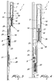
- a retention device for swing-leaves A is designated generally by the reference numeral 1.
- the retention device 1 for swing-leaves A comprises at least one hinge 2 constituted by at least one bracket 3 that is integral with the leaf, at least one tab 4 that is integral with a frame B (with respect to which the leaf A is pivoted), and at least one pivot 5, which is accommodated at least partially within the hinge 2.
- At least one between the at least one bracket 3 and the at least one tab 4 comprises an internal cavity 6 whose shape and dimensions are complementary to those of a preferably substantially frustum-like first end 7 of the pivot 5.
- the pivot 5, moreover, is capable of translating parallel to its own axis, by way of the action of a respective actuator 8, between a first free configuration, in which it is spaced from the internal cavity 6 (see Figures 9 and 12 by way of example), and a second blocking configuration, in which it is inserted within the cavity 6 (see Figures 10 and 11 by way of example), resting with at least one portion of its outer surface on at least one corresponding portion of the inner surface of the cavity 6, with consequent mutual retention (such mutual retention can be achieved, for example, by friction).
- the device 1 can be arranged in the second configuration at substantially any orientation of the leaf A with respect to the frame B, with the advantage, with respect to blocking units of the known type, of not limiting the possibility to fix the leaf A only at its two extreme configurations.
- the brackets 3 that are integral with the leaf A are two in number, a first fixed bracket 3a and a second bracket 3b that can slide along a predefined stroke.
- the pivot 5 is integral with the second sliding bracket 3b.
- the second sliding bracket 3b is interposed between the pivot 5 and the respective actuator 8.
- the first fixed bracket 3a has a first portion 9 for retention to the leaf A and a second portion 10, which is arranged substantially opposite the first portion 9, that protrudes with respect to the leaf A, in the configuration for use, and is provided with a substantially cylindrical seat 11 for the free accommodation of at least one substantially central part of the pivot 5.
- the first portion 9 can be fixed to the leaf A by interlocking, gluing and/or with any other method of the known type.
- the laminar portion of the bracket 3a interposed between the portion 10 and the portion 11, thanks to the blocking on the two opposite faces, will be not subjected to a bending moment and thus will not be subject to mechanical fatigue failure.
- the screws 12 can have fixing plates accommodated slidingly within the shaped grooves of the profiles that constitute the leaf A and the frame B: the respective screw engages in a hole of the plate, clamping the profile.
- This constructive solution has the undeniable advantage of adjusting with extreme precision the arrangement of the hinge 2, and optionally of modifying its position during maintenance.
- brackets 3a and 3b and tabs 4 in which there are shaped grooves within which the head of a screw, which is screwed on the profile (which constitutes the leaf A and/or the frame B), can be accommodated slidingly is not ruled out: in this case also, the screw constitutes an alignment element that determines the specific arrangement of the bracket 3a or 3b and/or of the tab 4.
- the arrangement of additional fastening screws allows the installer to decide the exact height to assign to the component, with the assurance that the alignment is ensured in any case by the head of the screw that slides within the shaped groove.
- the second sliding bracket 3b has a first band 13 for retention to a movable sliding block 14 of the actuator 8 that is accommodated on the leaf A, and a second band 15, which is substantially opposite the first band 13, protruding with respect to the leaf A in the configuration for use, and is provided with a substantially cylindrical compartment 16 for the free accommodation of a second end 17, opposite the first end 7, of the pivot 5.
- end 7 of the pivot 5 is positively frustum-shaped.
- the internal cavity 6 of the at least one tab 4 is also frustum-shaped and has a shape and dimensions that are complementary to those of the end 7 of the pivot 5 in order to ensure optimum coupling therewith in the cited second blocking configuration.
- end 7 of the pivot 5 can comprise preferably, on at least one wall thereof that faces outwardly, a plurality of raised portions and contoured regions.
- contoured regions of the end 7 have the purpose of ensuring a stable coupling that does not entail mutual interference but only friction: the contoured regions and the raised portions prevent the end 7 and the cavity 6 from mutually coupling rigidly as a bevel gear pair; their coupling, by way of these contoured regions and raised portions, is therefore always removable by way of the action of the actuator 8.
- the pivot 5 comprises means 18 for facilitated assembly: the means 18 have the purpose of allowing its upright or inverted installation (depending on whether it has to be installed in a leaf A that opens to the right and/or to the left) and it is in fact possible to disassemble the bracket 3b and assemble it again with the opposite orientation by way of the presence of the means 18.
- the means 18 might also allow an adjustment of the protrusion of the pivot 5 from the bracket 3b: in practice, by adopting the means 18 it is possible to move the end 7 closer (when the device is in the free configuration) and/or away with respect to the cavity 6 (if adjustment is necessary due to a less than perfect assembly).
- This adjustment is extremely advantageous, since it allows to adapt during installation (if the brackets 3a and 3b and the tab 4 are not at the ideal design distance due to a mistake of the installation technician) the position of the pivot 5 in order to ensure that when it is moved into the blocking configuration it engages stably in the cavity 6.
- the adjustment means 18 might also allow to adapt the device 1 to the dimensional variations induced by temperature variations: it should be noted that shutters, blinds and leaves A in general are exposed outdoors and thus are struck directly by solar radiation and/or by wind. It is thus very probable that expansions and/or contractions occur which might not be consistent with the corresponding dimensional variations of the components of the device 1 (for example because they are made of different materials, characterized therefore by a different coefficient of thermal expansion).
- the actuator 8 comprises an enclosure 19, which is integral with the leaf A and is accommodated thereon, and a movable slider 20 that is coupled to a sliding block 14 that is integral with a second end 17 of the pivot 5.
- the enclosure 19 and the sliding block 14 are mutually integral so that they can move only together, translating by way of the action of the actuator 8.
- the slider 20 can move between a retracted arrangement, which corresponds to the first free configuration of the pivot 5 (see Figures 9 and 12 by way of example), and a forward arrangement, which corresponds to the configuration for blocking the pivot 5 with respect to the cavity 6 (see Figures 10 and 11 by way of example).
- elastic disconnection means 21 are interposed between the movable slider 20 and the sliding block 14.
- the elastic means 21 are intended to maintain, in the absence of external actions, the maximum mutual distance between the sliding block 14 and the slider 20: such maximum mutual distance is generally defined by the dimensions of the recess of the enclosure 19 within which the sliding block 14 and the slider 20 are enclosed at least partially.
- a threaded element 22 is interposed, moreover, between the movable slider 20 and the sliding block 14 to adjust the "preloading" of the elastic means 21, increasing or reducing their elastic mechanical action, simply by varying the position of the threaded element 22 (generally by rotating it, by means of a specific tool, in order to adjust its protrusion with respect to the point for coupling to the enclosure 19).
- the threaded element 22 can be used during installation in order to adjust the position of the component 24, interposed between the slider 20 and the elastic means 21.
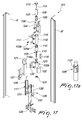
- the slider 20 can be coupled to respective manually-actuated movement elements 26, which comprise a skid 27, which is retained to the slider 20 and can slide on the leaf A, and a lever 28, which is pivoted on the leaf A with respect to a first axis 29 and is pivoted on the skid 27 with respect to a second axis 30.
- the orientation of the lever 28 produces translations of the skid 27 that are equal in length at most to twice the distance between the first axis 29 and the second axis 30.
- Such translations are suitable for a movement of the entire kinematic chain with consequent lifting or lowering of the pivot 5 up to its engagement or respectively disengagement in the cavity 6.
- the present invention solves the problems described previously, proposing a retention device 1 for swing-leaves A which, even in the event of strong gusts of wind (or other external actions applied to the leaf A), is capable of moving the leaf A in retention conditions, does not cause any damage to the leaf A, the frame B and/or the respective pintles.
- the coupling of the end 7 of the pivot 5 with the cavity 6 is such as to prevent the movements of the leaf A in standard conditions: in the event of a strong gust of wind, a collision by a user or any external action suitable to move the leaf A, the presence of the elastic means 21 within the actuator 8 and the fact that the end 7 and the inner surface of the cavity 6 can be made of polymeric material with predefined elastic deformability, the leaf A can move (oriented by the wind or by another external action) without any part of the leaf A, of the frame B and/or of the pintles being subjected to any damage.
- the device 1 allows safe blocking of the leaf A: the presence of the contoured regions in the end 7 ensures in fact that a friction coupling is provided which increases its retention.
- end 7 and the inner surfaces of the cavity 6 can be made of polymeric material with predefined deformability allows (if external actions occur on the leaf A which are intended to move it) a mutual movement (of the end 7 of the pivot 5 in the cavity 6) as a consequence of the elastic deformation of such components.
- the device 1 allows to retain the leaf A substantially in any configuration defined between the maximum opening configuration and the closed configuration; this occurs because the pivot 5 can assume the second retention configuration with respect to the cavity 6 at any orientation of the leaf (except for the orientations that prevent the user from accessing the actuator 8 and actuating it).
- the device 1 has low costs, being also relatively simple to provide and safe in use.
- the possibility to apply the device 1 on leaves A that are already installed and/or to fit them during production is specified.
- the device 1 according to the invention can be an additional component, which can be installed on a door or window frame that is already installed and therefore in addition to the existing hinges and pintles.
- the adoption of a constructive solution in which the device 1 constitutes the hinging pintles of the leaf A is not ruled out (if so, there can be a single device in cooperation with hinges of the standard type or multiple devices spread along an edge of said leaf A).
- This solution allows to have a leaf A that can orient itself freely when the device 1 is in the free position, but can also be blocked in any intermediate configuration between the closing one and the one for complete opening through 180° of said leaf A with respect to the frame B.
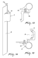
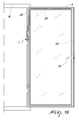
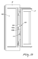
- the device 1 in a constructive solution of undeniable practical and applicative interest (illustrated exclusively by way of non-limiting example in the accompanying Figure 16 ), can be actuated directly by means of a handle 32 for casements (for example of the type usually known "cremone bolt” and/or "olive-shaped window knob").
- the handles 32 are usually connected to specific motion transmission assemblies 33 designed to allow the engagement/disengagement of adapted elements for blocking the leaf A within respective seats of the frame B (in order to pass from the closed configuration to the open configuration of the leaf).
- the motion transmission assemblies 33 described can also allow the leaf A to assume also a further partially open configuration (in so-called vasistas leaves, i.e., which allow a rotation of the leaf A generally with respect to its base, with consequent provision of an upper and lateral opening for the free circulation of air).
- Leaves A of this type i.e., provided with a handle 32, are particularly suitable for installing the device 1 according to the invention, since it can be connected easily to the kinematic chain associated with the handle 32.
- the device 1 therefore will be arranged laterally adjacent to normal blocking elements of the leaf A in the frame B in order to ensure stability of the closure, when the leaf A is inserted in the frame B.
- the end 7 of the pivot 5 is separated from the cavity 6 and does not interfere therewith, and thus the device 1 behaves like a normal free hinge about which the leaf A can rotate freely.
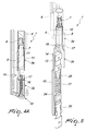
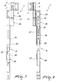
- a friction-controlled retention device for swing-leaves A' is designated generally by the reference numeral 101.
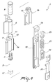
- the friction-controlled retention device 101 comprises at least one hinge 102 constituted by at least one bracket 103 that is integral with the leaf A', at least one tab 104 that is integral with a fixed frame B', and at least one pivot 105, which is accommodated at least partially within the at least one hinge 102.
- At least one between the at least one bracket 103 and the at least one tab 104 comprises an internal cavity 106 for the accommodation of at least one bushing 107 made of polymeric material that has a seat 108 for at least one rigid shell 109 provided with an internal cavity whose shape and dimensions are complementary to those of a first end 110 of the pivot 105.
- the pivot 105 is able to translate parallel to its own axis, by way of the action of a respective actuator 111, between a first free configuration, in which it is spaced from the internal compartment 112 of the shell 109, and a second blocking configuration, in which it is inserted within the compartment 112, with resting of at least one portion of its outer surface on at least one corresponding portion of the inner surface of the compartment 112 and consequent mutual retention by interference.
- the actuator 111 can be any device capable of generating (directly or indirectly) a translation of the pivot 105: it is evident, therefore, that the constructive solution shown in the accompanying figures has only a non-limiting function of exemplifying the type of actuator that is suitable to move the device 101 according to the invention.
- the tab 104 comprises the internal cavity 106, it can comprise a plug 113, which in turn is accommodated on the top of the tab 104: this constructive solution is particularly simple from a constructive point of view.
- the threaded element 114 can be preferably of the self-locking type in order to avoid unwanted retrograde rotations.
- This particular adjustment allows to obtain an optimum mutual arrangement of the bushing 107 in the internal cavity 106 with subsequent optimum meshing of the end 110 of the pivot 105 with the inner surface of the compartment 112 of the shell 109, in the blocking configuration.
- the element 114 adjusts friction intensity for the friction-control of the device 101.
- the pivot 105 can have an end 110 that has a diameter that corresponds to the inside diameter of the rigid shell 109 and a substantially central portion 115 having a smaller diameter, for accommodating a substantially tubular elastic element 116 intended to force the end 110 in the internal compartment 112 of the shell 109.
- the substantially central portion 115 can be constituted at least partially by a threaded bar.
- brackets 103 that are integral with the leaf A' are two in number, a first fixed bracket 103a and a second bracket 103b that can slide along a predefined stroke (integrally with the movable end of the respective actuator 111).
- the pivot 105 is, in this case, integral with the second sliding bracket 103b: the second sliding bracket 103b is interposed between the pivot 105 and the respective actuator 111.
- the first fixed bracket 103a has a first portion 117 for retention to the leaf A' and a second portion 118, which is arranged substantially opposite the first portion 117, which protrudes with respect to the leaf A' in the configuration for use and is provided with a substantially cylindrical seat 119 for the free accommodation of at least one substantially central part of the pivot 105.
- the fixed bracket 103a has, moreover, at least one longitudinal groove 119a inside its seat 119 which allows the accommodation of a respective ridge 105a of the pivot 105: the purpose of this constructive choice is to allow the vertical translation of the pivot 105 in the seat 119, preventing however its rotational movements (which would jeopardize the operation of the device 101).
- the second sliding bracket 103b has a first band 120 for retention to a movable slider 121 of the actuator 111 that is accommodated on the leaf A', and a second band 122, which is arranged substantially opposite the first band 120, protrudes with respect to the leaf A', in the configuration for use, and is provided with a substantially cylindrical compartment 123 for the abutment along one of its edges of a second end 124, arranged opposite the first end 110, of the pivot 105.
- the second end 124 is retained to the central portion 115 of the pivot 105: in particular, if the portion 115 is threaded, the second end comprises a threaded hole within which the threaded end of the portion 115 can engage stably.
- the elastic element 116 in the assembly configuration, is accommodated within the seat 119 of the fixed bracket 103a, fitted on the substantially central portion 115 of the pivot 105.
- the purpose of the elastic element 116 is to force upwardly the end 110 of the pivot 105, within the compartment 112 of the shell 109, when the device 101 is in the blocking configuration.
- the elastic element maintains the end 110 and the compartment 112 in mutual forcing: if, due to an external action (for example a gust of wind), a rotary forcing of the leaf A' occurs, the misalignment is compensated by the small rotation induced by the forcing and the elastic element 116 ensures the mutual meshing of the end 110 with the internal compartment 112.
- an externally threaded pad 116a is adopted which can be arranged at the preferred height within the compartment 123.
- At least one component selected between the end 110 of the pivot 105 and the internal compartment 112 of the shell 109 comprises, on at least one respective wall that faces outwardly, a plurality of raised portions and contoured regions having mutually substantially complementary shape and dimensions.
- the outer surface of the end 110 of the pivot 105 and the inner surface of the compartment 112 of the shell 109 can preferably have the shape of a six-point star, of the type of a so-called TORX® wrench, in order to provide stable and safe coupling.
- This particular complementary set of surface teeth allows safe coupling by interference of the two components; by means of this coupling it is possible to ensure efficient blocking of the leaf A' in any position with respect to the fixed frame B'.
- the shell 109 can have an outer surface provided with a plurality of contiguous raised portions, such as for example a so-called knurled surface and the like.
- a portion 110' of the outer surface of the pivot 105' and the inner surface of the cavity 112 of the shell 109 can preferably have the shape of a contour that has the profile of a set of teeth of the type used in car axle shafts. This shape allows to provide a stable, safe and highly resistant coupling, such as to preserve the functionalities of the set of teeth or rather not bend the teeth of the set of teeth due to the load applied by the pivot 105' inside the bushing 107.
- such set of teeth of the type used in car axle shafts is compliant with the ANSI (American National Standards Institute) standards, previously known also as ASA (American Standards Association) or with the DIN (Deutsches Institut für Normung) rules.
- ANSI American National Standards Institute
- ASA American Standards Association
- DIN Deutsches Institut für Normung
- the portion 110' is extended substantially along a partially central portion of the pivot 105' and does not comprise the ends of the pivot 105'.
- the rotation of the leaf A' with respect to the fixed frame B' can occur with respect to a vertical axis (like a normal window or door that can be opened in order to allow passage) or with respect to a horizontal axis (for example, in the case of vasistas leaves A', i.e., with tilt-down opening).
- the device 101 can perform its retaining action in relation to rotations of the leaf A' that occur about a vertical axis or a horizontal axis according to the manner in which it is installed and/or provided.
- the actuator 111 can be associated functionally with a motion transmission assembly controlled by a handle retained to the leaf A' and designed for its blocking/release on the frame B'.
- the handle and the motion transmission assembly are, in this case, of the type used traditionally in door or window frames.
- At least one portion of the motion transmission assembly is coupled to the slider of the actuator 111.
- the actuator 111 is integral with the leaf A', proximate to the first fixed bracket 103a and to the second sliding bracket 103b.
- the device 101 can be arranged in the second blocking configuration substantially at any orientation of the leaf A' with respect to the frame B', with the advantage, with respect to blocking assemblies of the known type, of not limiting the possibility to fix the leaf A' only at its two extreme configurations.
- bushing 107 is made of polymeric material and is fitted within the cavity 106 (optionally held in the correct position by the threaded element 114) is an undeniable advantage for the device 101.
- the bushing 107 can undergo elastic deformations that allow the shell 109 to rotate with respect to the bushing 107.
- the bushing 107 can be made preferably of polyamide (for example, polyoxymethylene (“POM”) commercially known also as Delrin, or Nylon®).
- polyamide for example, polyoxymethylene (“POM”) commercially known also as Delrin, or Nylon®.
- the fixing of the first portion 117 to the leaf A' can be provided by interlocking, gluing and/or with any other method of the known type.
- Brackets 103a and 103b and tabs 104 might also be adopted in which there are shaped grooves, within which the head of a screw, which is screwed on the profile (that constitutes the leaf A' and/or the frame B'), can be accommodated slidingly: in this case also, the screw constitutes an alignment element that determines the specific arrangement of the bracket (103a or 103b) and/or of the tab 104.
- the arrangement of further fastening screws allows the installer to decide the exact height to be assigned to the component, with the assurance that the alignment is in any case ensured by the head of the screw that slides within such shaped groove.
- end 110 of the pivot 105 is positively frustum-like (although the possibility to provide said end with a cylindrical or prism-like shape is not ruled out).
- the internal compartment 112 of the shell 109 also is frustum-like and has a shape and dimensions that are complementary to those of the end 110 of such pivot 105 in order to ensure optimum coupling therewith in said second blocking configuration.
- the pivot 105 is constituted by multiple components mutually interconnected by means of specific threaded portions (or other type of retention): such threaded portions have the purpose of allowing its upright or inverted installation (depending on whether it has to be installed in a leaf A' that opens to the right and/or to the left); it is in fact possible to remove the bracket 103b and reassemble it with the opposite orientation.
- the presence of the threaded portions allows to simplify the arrangement of the elastic element 116 on the central portion 115 (optionally retained by the pad 116a), when the pivot 105 is arranged within the seat 119 of the bracket 103a.
- Such threaded portions might also allow an adjustment of the protrusion of the pivot 105 from the bracket 103b in order to simplify the assembly operations on the part of the installer.
- This adjustment is extremely advantageous because it allows to adapt, in fact, during installation (if the brackets 103a and 103b and the tab 104 are not at the ideal design distance due to an error by the installer), the placement of the pivot 105 in order to ensure that when it is moved to the blocking configuration it engages stably within the internal compartment 112.
- the actuator 111 can comprise a plate 126, which is integral with the leaf A' and is accommodated thereon, and the movable slider 121 that is integral with the second end 124 of the pivot 105.
- the slider 121 is movable between a retracted arrangement, which corresponds to the first free configuration of the pivot 105, and a forward arrangement, which corresponds to the configuration for blocking the pivot 105 with respect to the compartment 112.
- the slider 121 can be coupled to respective manually-actuated movement elements 128, which comprise a skid 129, which is coupled to the slider 121 and can slide on the leaf A', and a lever 130, which is pivoted on the leaf A' with respect to a first axis 131 and is pivoted on the skid 129 with respect to a second axis 132.
- the orientation of the lever 128 produces translations of the skid 127 that are equal in length at most to twice the distance between the first axis 129 and the second axis 132.
- Such translations are suitable for a movement of the whole kinematic chain with consequent lifting, respectively lowering, of the pivot 105 up to its engagement, respectively disengagement, in the internal compartment 112.
- the present invention solves the problems described previously, by proposing a retention device 101 for swing-leaves A' that, even in the event of strong gusts of wind (or other external actions applied to the leaf A') capable of moving the leaf A' even if the leaf is in retention conditions, does not cause any damage to the leaf A', the frame B' and/or the respective pintles.
- the coupling of the end 110 of the pivot 105 with the compartment 112 is such to prevent the movements of the leaf A' in standard conditions; if a strong gust of wind, an impact by a user or any other external action suitable to move the leaf A' occurs, the presence of the bushing 107 made of polymeric material (which thus may deform within the bracket 104) in fact will allow the leaf A' to move (oriented by the wind or by another external action) without any part of the leaf A', the frame B' and/or the pintles being subject to any damage.
- the device 101 allows to block safely the leaf A': the presence of the contoured regions in the end 110 ensures in fact that a friction coupling is provided which by improving its tightness (this result is even more evident if one considers the possibility to provide an end 110 and a cavity 112 having a shape of a six-point star like a so-called TORX® wrench).
- the bushing 107 can be made of polymeric material with predefined deformability allows (if external actions occur on the leaf A' which are intended to move it) a mutual movement (of the shell 109 within the bushing 107) following the elastic deformation of the bushing 107.
- the device 101 allows to retain the leaf A' substantially in any configuration defined between the configuration of maximum opening and the closed configuration; this occurs because the pivot 105 can assume the second blocking configuration with respect to the internal compartment 112 at any orientation of the leaf A' (except for the orientations that prevent the user from accessing the actuator 111 and actuating it).
- the device 101 has low costs and is also relatively simple to provide and safe in use. It is specified that it is possible to apply the device 101 on leaves A' that are already installed and/or to install it during production.
- the device 101 can be an additional component, which can be installed on a casement that is already installed and thus in addition to the existing hinges and pintles.
- the adoption of a constructive solution in which the device 101 constitutes the hinging pintles of the leaf A' is not ruled out (in this case, there can be a single device in cooperation with hinges of the standard type or multiple devices arranged along an edge of said leaf A').
- This solution allows to have a leaf A' that can orient itself freely when the device 101 is in the free position, but can also be blocked in any intermediate configuration between the closure configuration and the fully open configuration at 180° of the leaf A' with respect to the frame B'.
- the device 101 could be actuated directly by means of a handle for casements (for example of the type usually called “cremone bolt” and/or “olive-shaped window knob"), which in this case composes part of the actuator 111.
- casements for example of the type usually called "cremone bolt” and/or “olive-shaped window knob"
- handles are usually connected to specific motion transmission assemblies designed to allow the engagement/disengagement of adapted elements for blocking the leaf A' within respective seats of the frame B' (in order to pass from the closing configuration to the open configuration of the leaf).
- Leaves A' of this type i.e., provided with a handle, are particularly suitable for the installation of the device 101 according to the invention, because said device can be connected easily to the kinematic chain associated with the handle.
- the device 101 is therefore arranged laterally with respect to normal blocking elements of the leaf A' in the frame B' in order to ensure stability of the closure, when the leaf A' is inserted in the frame B'.
- the end 110 of the pivot 105 is separated from the internal compartment 112 and does not interfere with the shell 109 and thus the device 101 behaves like a normal free hinge about which the leaf A' can rotate freely.
- the materials used, as well as the dimensions, may be any according to requirements and to the state of the art.
Landscapes
- Engineering & Computer Science (AREA)
- Mechanical Engineering (AREA)
- Tea And Coffee (AREA)
- Pivots And Pivotal Connections (AREA)
Applications Claiming Priority (2)
| Application Number | Priority Date | Filing Date | Title |
|---|---|---|---|
| IT000389A ITBO20130389A1 (it) | 2013-07-23 | 2013-07-23 | Dispositivo di vincolo per ante a battente |
| IT000559A ITBO20130559A1 (it) | 2013-10-14 | 2013-10-14 | Dispositivo di vincolo frizionato per ante a battente |
Publications (2)
| Publication Number | Publication Date |
|---|---|
| EP2829677A2 true EP2829677A2 (de) | 2015-01-28 |
| EP2829677A3 EP2829677A3 (de) | 2015-03-18 |
Family
ID=51211149
Family Applications (1)
| Application Number | Title | Priority Date | Filing Date |
|---|---|---|---|
| EP14178149.2A Withdrawn EP2829677A3 (de) | 2013-07-23 | 2014-07-23 | Rückhaltevorrichtung für Schwenkflügel |
Country Status (1)
| Country | Link |
|---|---|
| EP (1) | EP2829677A3 (de) |
Family Cites Families (2)
| Publication number | Priority date | Publication date | Assignee | Title |
|---|---|---|---|---|
| EP0502267A1 (de) * | 1991-02-01 | 1992-09-09 | Yin-Ping Sheu | Vorrichtung zur Winkeleinstellung |
| IT1399740B1 (it) * | 2010-05-04 | 2013-05-03 | Maria De | Cerniera bloccante |
-
2014
- 2014-07-23 EP EP14178149.2A patent/EP2829677A3/de not_active Withdrawn
Non-Patent Citations (1)
| Title |
|---|
| None |
Also Published As
| Publication number | Publication date |
|---|---|
| EP2829677A3 (de) | 2015-03-18 |
Similar Documents
| Publication | Publication Date | Title |
|---|---|---|
| EP2710212B1 (de) | Kolbenvorrichtung zur kontrollierten drehbaren bewegung von türen, klappen oder dergleichen | |
| US9512658B2 (en) | Device for opening and closing a pivoting wing | |
| EP3211161B1 (de) | Aufklappfensterbeschläge | |
| CN110630146B (zh) | 一种装配式建筑门窗 | |
| KR102564419B1 (ko) | 손가락 끼임 방지 도어 | |
| RU2662696C2 (ru) | Фурнитура для, как минимум, подъёмной, а предпочтительно также и передвижной створки окна или двери | |
| EP4390030B1 (de) | Dachfenster mit einer hubvorrichtung und verfahren zur montage einer hubvorrichtung | |
| KR101067878B1 (ko) | 문틈 차단장치 | |
| CA3009381A1 (en) | Upwardly pivoted window with biasing to retain sash open | |
| BR112019017854B1 (pt) | Fecho de barra de empurrar para uma carcaça do armário de distribuição, bem como disposição correspondente e método correspondente | |
| EP3321458B1 (de) | Scharnieranordnung, insbesondere eine verdeckte scharnieranordnung | |
| EP2829677A2 (de) | Rückhaltevorrichtung für Schwenkflügel | |
| EP2447452A1 (de) | Schließblech für ein Schloss, Anordnung aus Schließblech und Schloss und/oder eines Schließelements und Verfahren zum Schließen eines Schließelements | |
| EP3039207B1 (de) | Flügel für ein schiebefenster oder eine schiebetür und schiebefenster oder schiebetür damit | |
| KR20200125953A (ko) | 창문 또는 도어의 슬라이딩 새시 또는 슬라이딩 가능한 리프트-슬라이딩 새시를 커버링하기 위한 장치 | |
| AU2014227553A1 (en) | Double hung window assembly | |
| EP3455439B1 (de) | Verschluss für eine tür und/oder ein fenster | |
| JP7055036B2 (ja) | 建具 | |
| KR200180534Y1 (ko) | 미닫이 창문의 개폐 로울러 구조 | |
| EP3578738B1 (de) | Betriebsmechanismus für eine hebe-schiebetür und eine mit einem solchen mechanismus ausgestattete hebe-schiebetür | |
| EP3093419A1 (de) | Sicherheitsvorrichtung für ein fenster | |
| CN213869327U (zh) | 一种用于内开内倒门窗的锁盒结构 | |
| EP2924208B1 (de) | Gegen gewaltsames eindringen beständiges schloss | |
| JP6757146B2 (ja) | 窓開閉装置 | |
| EP4234873B1 (de) | Lamellenkontrolsystem |
Legal Events
| Date | Code | Title | Description |
|---|---|---|---|
| 17P | Request for examination filed |
Effective date: 20140723 |
|
| AK | Designated contracting states |
Kind code of ref document: A2 Designated state(s): AL AT BE BG CH CY CZ DE DK EE ES FI FR GB GR HR HU IE IS IT LI LT LU LV MC MK MT NL NO PL PT RO RS SE SI SK SM TR |
|
| AX | Request for extension of the european patent |
Extension state: BA ME |
|
| PUAI | Public reference made under article 153(3) epc to a published international application that has entered the european phase |
Free format text: ORIGINAL CODE: 0009012 |
|
| PUAL | Search report despatched |
Free format text: ORIGINAL CODE: 0009013 |
|
| RIN1 | Information on inventor provided before grant (corrected) |
Inventor name: DE MARIA, FABIO Inventor name: AGLIOLO QUARTALARO, ANTONINO |
|
| AK | Designated contracting states |
Kind code of ref document: A3 Designated state(s): AL AT BE BG CH CY CZ DE DK EE ES FI FR GB GR HR HU IE IS IT LI LT LU LV MC MK MT NL NO PL PT RO RS SE SI SK SM TR |
|
| AX | Request for extension of the european patent |
Extension state: BA ME |
|
| RIC1 | Information provided on ipc code assigned before grant |
Ipc: E05D 11/10 20060101AFI20150206BHEP Ipc: E05D 11/08 20060101ALI20150206BHEP |
|
| R17P | Request for examination filed (corrected) |
Effective date: 20150811 |
|
| RBV | Designated contracting states (corrected) |
Designated state(s): AL AT BE BG CH CY CZ DE DK EE ES FI FR GB GR HR HU IE IS IT LI LT LU LV MC MK MT NL NO PL PT RO RS SE SI SK SM TR |
|
| 17Q | First examination report despatched |
Effective date: 20190410 |
|
| STAA | Information on the status of an ep patent application or granted ep patent |
Free format text: STATUS: THE APPLICATION IS DEEMED TO BE WITHDRAWN |
|
| 18D | Application deemed to be withdrawn |
Effective date: 20200201 |