EP2829471B1 - Taumelscheibenfreies Koaxialdrehflügelflugzeug - Google Patents
Taumelscheibenfreies Koaxialdrehflügelflugzeug Download PDFInfo
- Publication number
- EP2829471B1 EP2829471B1 EP14177865.4A EP14177865A EP2829471B1 EP 2829471 B1 EP2829471 B1 EP 2829471B1 EP 14177865 A EP14177865 A EP 14177865A EP 2829471 B1 EP2829471 B1 EP 2829471B1
- Authority
- EP
- European Patent Office
- Prior art keywords
- rotor
- ibcs
- generator
- rotary wing
- wing aircraft
- Prior art date
- Legal status (The legal status is an assumption and is not a legal conclusion. Google has not performed a legal analysis and makes no representation as to the accuracy of the status listed.)
- Not-in-force
Links
- 230000005540 biological transmission Effects 0.000 claims description 19
- 230000007246 mechanism Effects 0.000 claims description 9
- 238000004146 energy storage Methods 0.000 claims description 7
- 230000004044 response Effects 0.000 claims description 4
- 238000004804 winding Methods 0.000 description 4
- 230000008901 benefit Effects 0.000 description 3
- 125000004122 cyclic group Chemical group 0.000 description 3
- 238000006073 displacement reaction Methods 0.000 description 3
- 230000009977 dual effect Effects 0.000 description 3
- 230000001133 acceleration Effects 0.000 description 2
- 230000000712 assembly Effects 0.000 description 2
- 238000000429 assembly Methods 0.000 description 2
- 230000008878 coupling Effects 0.000 description 2
- 238000010168 coupling process Methods 0.000 description 2
- 238000005859 coupling reaction Methods 0.000 description 2
- 230000004075 alteration Effects 0.000 description 1
- 238000005452 bending Methods 0.000 description 1
- 150000001875 compounds Chemical class 0.000 description 1
- 230000001419 dependent effect Effects 0.000 description 1
- 239000000835 fiber Substances 0.000 description 1
- 230000036541 health Effects 0.000 description 1
- 230000006872 improvement Effects 0.000 description 1
- 238000005461 lubrication Methods 0.000 description 1
- 238000012423 maintenance Methods 0.000 description 1
- 238000005259 measurement Methods 0.000 description 1
- 238000012544 monitoring process Methods 0.000 description 1
- 230000009467 reduction Effects 0.000 description 1
- 230000003068 static effect Effects 0.000 description 1
- 238000006467 substitution reaction Methods 0.000 description 1
Images


Classifications
-
- B—PERFORMING OPERATIONS; TRANSPORTING
- B64—AIRCRAFT; AVIATION; COSMONAUTICS
- B64C—AEROPLANES; HELICOPTERS
- B64C27/00—Rotorcraft; Rotors peculiar thereto
- B64C27/54—Mechanisms for controlling blade adjustment or movement relative to rotor head, e.g. lag-lead movement
- B64C27/80—Mechanisms for controlling blade adjustment or movement relative to rotor head, e.g. lag-lead movement for differential adjustment of blade pitch between two or more lifting rotors
-
- B—PERFORMING OPERATIONS; TRANSPORTING
- B64—AIRCRAFT; AVIATION; COSMONAUTICS
- B64C—AEROPLANES; HELICOPTERS
- B64C27/00—Rotorcraft; Rotors peculiar thereto
- B64C27/04—Helicopters
- B64C27/08—Helicopters with two or more rotors
- B64C27/10—Helicopters with two or more rotors arranged coaxially
-
- B—PERFORMING OPERATIONS; TRANSPORTING
- B64—AIRCRAFT; AVIATION; COSMONAUTICS
- B64C—AEROPLANES; HELICOPTERS
- B64C27/00—Rotorcraft; Rotors peculiar thereto
- B64C27/54—Mechanisms for controlling blade adjustment or movement relative to rotor head, e.g. lag-lead movement
- B64C27/72—Means acting on blades
-
- H—ELECTRICITY
- H02—GENERATION; CONVERSION OR DISTRIBUTION OF ELECTRIC POWER
- H02K—DYNAMO-ELECTRIC MACHINES
- H02K99/00—Subject matter not provided for in other groups of this subclass
- H02K99/10—Generators
-
- B—PERFORMING OPERATIONS; TRANSPORTING
- B64—AIRCRAFT; AVIATION; COSMONAUTICS
- B64C—AEROPLANES; HELICOPTERS
- B64C27/00—Rotorcraft; Rotors peculiar thereto
- B64C27/54—Mechanisms for controlling blade adjustment or movement relative to rotor head, e.g. lag-lead movement
- B64C27/72—Means acting on blades
- B64C2027/7205—Means acting on blades on each blade individually, e.g. individual blade control [IBC]
- B64C2027/7211—Means acting on blades on each blade individually, e.g. individual blade control [IBC] without flaps
- B64C2027/7216—Means acting on blades on each blade individually, e.g. individual blade control [IBC] without flaps using one actuator per blade
-
- B—PERFORMING OPERATIONS; TRANSPORTING
- B64—AIRCRAFT; AVIATION; COSMONAUTICS
- B64C—AEROPLANES; HELICOPTERS
- B64C27/00—Rotorcraft; Rotors peculiar thereto
- B64C27/82—Rotorcraft; Rotors peculiar thereto characterised by the provision of an auxiliary rotor or fluid-jet device for counter-balancing lifting rotor torque or changing direction of rotorcraft
- B64C2027/8236—Rotorcraft; Rotors peculiar thereto characterised by the provision of an auxiliary rotor or fluid-jet device for counter-balancing lifting rotor torque or changing direction of rotorcraft including pusher propellers
-
- B—PERFORMING OPERATIONS; TRANSPORTING
- B64—AIRCRAFT; AVIATION; COSMONAUTICS
- B64C—AEROPLANES; HELICOPTERS
- B64C27/00—Rotorcraft; Rotors peculiar thereto
- B64C27/04—Helicopters
- B64C27/12—Rotor drives
-
- B—PERFORMING OPERATIONS; TRANSPORTING
- B64—AIRCRAFT; AVIATION; COSMONAUTICS
- B64C—AEROPLANES; HELICOPTERS
- B64C27/00—Rotorcraft; Rotors peculiar thereto
- B64C27/32—Rotors
-
- Y—GENERAL TAGGING OF NEW TECHNOLOGICAL DEVELOPMENTS; GENERAL TAGGING OF CROSS-SECTIONAL TECHNOLOGIES SPANNING OVER SEVERAL SECTIONS OF THE IPC; TECHNICAL SUBJECTS COVERED BY FORMER USPC CROSS-REFERENCE ART COLLECTIONS [XRACs] AND DIGESTS
- Y02—TECHNOLOGIES OR APPLICATIONS FOR MITIGATION OR ADAPTATION AGAINST CLIMATE CHANGE
- Y02T—CLIMATE CHANGE MITIGATION TECHNOLOGIES RELATED TO TRANSPORTATION
- Y02T50/00—Aeronautics or air transport
- Y02T50/30—Wing lift efficiency
Definitions
- Exemplary embodiments of the invention generally relate to rotary wing aircrafts, and more particularly, to a control system for pitching the blades of a rotor on a rotary wing aircraft.
- Control of a rotary wing aircraft is affected by varying the pitch of the rotor blades individually as the rotor rotates and by varying the pitch of all of the blades together. These are known respectively as cyclic and collective pitch control. Blade pitch control of a rotary wing aircraft main rotor is commonly achieved through a swashplate.
- the swashplate is typically concentrically mounted about the rotor shaft.
- the swashplate generally includes two rings connected by a series of bearings with one ring connected to the airframe (stationary swashplate).
- the rotating ring is connected to the rotor hub through a pivoted link device typically referred to as "scissors", with the static ring similarly connected to the airframe.
- the rotating swashplate rotates relative the stationary swashplate. Apart from rotary motion, the stationary and rotating swashplate otherwise move as a unitary component. Cyclic control is achieved by tilting the swashplate relative to a rotor shaft and collective control is achieved by translating the swashplate along the rotor shaft.
- GB 2 387 157 A discloses a rotor pitch control system comprising generators for creating power for the pitch control system and under GB 2 280 412 A rotor system is shown which is controlled by light signals.
- Pitch control rods mounted between the main rotor blades and the rotating swashplate transfer loads between the swashplate and the main rotor blades.
- Main rotor servos extend between and attach to the stationary swashplate and the aircraft fuselage. Displacement of the main rotor servos results in displacement of the stationary swashplate. Hence, by actuating selected main rotor servos, collective and cyclic commands are transferred to the rotor head as vertical and/or tilting displacement of the swashplates.
- the invention relates to a main rotor system and rotary wing aircraft according to claims 1 and 6. Embodiments are subject matter of the dependent claims.
- a main rotor system of an aircraft including a first rotor coupled to a transmission and configured to rotate about an axis in a first direction.
- a second rotor is similarly coupled to the transmission and is configured to rotate about the axis in a second direction.
- the first rotor includes a first individual blade control system blades (IBCS) configured to adjust a pitch of each of a plurality of blades of the first rotor independently
- the second rotor includes a second IBCS configured to adjust a pitch of each of a plurality of blades of the second rotor independently.
- IBCS individual blade control system blades
- At least one slip ring is configured to transmit electrical power and/or a control signal to the first and second IBCS.
- the main rotor according to the invention further comprises a standpipe fixedly arranged generally concentrically between the first rotor and the second rotor, wherein the at least one slip ring is mounted to the standpipe
- the main rotor according to the invention also further comprises a generator mounted to the first rotor, the generator including an engagement mechanism configured to engage a portion of the standpipe such that power is generated by the generator as the first rotor is rotated about the first axis.
- the first rotor includes a first IBCS and the second rotor includes a second IBCS.
- the first slip ring may be configured to transmit electrical power and/or a first control signal to the first IBCS and the second slip ring may be configured to transmit electrical power and/or a second control signal to the second IBCS.
- the IBCS further may comprise: a plurality of actuators, each of which is configured to rotate one of the plurality of rotor blades about a second axis, arranged at an angle to the first axis; and at least one controller having a plurality of channels, each actuator being operably coupled to one of the plurality of channels such that the at least one controller is configured to operate the actuators in response to a control signal.
- the at least one slip ring may be configured to transmit electrical power and/or the control signal to the at least one controller via one or more wires.
- the at least one slip ring may be configured to transmit electrical power and/or the control signal to the at least one controller wirelessly.
- the at least one controller of the IBCS may be configured to receive the control signal optically.
- a rotary wing aircraft including an airframe having one or more engines mounted thereto.
- a main rotor system includes a first rotor and a second rotor.
- the first rotor includes a first rotor hub and a plurality of first blades extending outwardly therefrom.
- the first rotor is coupled to a transmission and is configured to rotate about an axis in a first direction.
- the second rotor includes a second rotor hub and a plurality of second blades extending outwardly therefrom.
- the second rotor is similarly coupled to the transmission and is configured to rotate about the axis in a second direction.
- At least one slip ring is configured to transmit electrical power and/or a control signal to the at least one IBCS.
- the first rotor includes a first individual blade control system (IBCS) configured to adjust a pitch of each of the plurality of first blades independently and the second rotor includes a second IBCS configured to adjust the pitch of each of the plurality of second blades independently.
- IBCS individual blade control system
- At least one Slip ring is configured to transmit electrical power and/or a control signal to the first IBCS and the second IBCS.
- Particular embodiments may include any of the following optional features, alone or in combination:
- the rotary wing aircraft further may comprise an energy storage device configured to receive a portion of the electrical energy converted by the generator, wherein the energy storage device may be configured to transmit power to at least one of the first IBCS and the second IBCS.
- a first slip ring may be connected to the first rotor adjacent the transmission and a second slip ring may be connected to the second rotor near the transmission.
- the first slip ring may be configured to transmit electrical power and/or a first control signal to the first IBCS and the second slip ring may be configured to transmit electrical power and/or a second control signal to the second IBCS.
- each of the first IBCS and the second IBCS further may comprise: a plurality of actuators, each of which is configured to rotate one of the plurality of rotor blades about a second axis, arranged at an angle to the first axis; and at least one controller having a plurality of channels, each actuator being operably coupled to one of the plurality of channels such that the at least one controller is configured to operate the actuators in response to a control signal.
- the rotary wing aircraft further may comprise a control system configured to generate the control signal, the control signal including waveform coefficients.
- the waveform coefficients transmitted to the at least one controller may be determined using inceptor data and sensor data.
- the waveform coefficients may include a higher harmonic control signals.
- the rotary wing aircraft further may comprise a standpipe fixedly arranged generally concentrically between the first rotor and the second rotor, wherein the at least one slip may be ring mounted to the standpipe.
- the rotary wing aircraft further comprise: a generator mounted to the first rotor, the generator including an engagement mechanism configured to engage a portion of the standpipe such that power is generated by the generator as the first rotor is rotated about the axis.
- a first generator may be mounted to the first rotor and a second generator may be mounted to the second rotor.
- Power generated by the first generator may be configured to operate the first IBCS
- power generated by the second generator may be configured to operate the second IBCS
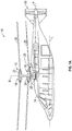
- FIGS. 1A and 1B illustrate an exemplary vertical takeoff and landing (VTOL) high speed compound or coaxial contra-rotating rigid rotor aircraft 10 having a dual, contra-rotating main rotor system 12, which rotates about an axis of rotation R.
- the aircraft includes an airframe 14 which supports the dual, contra-rotating, coaxial main rotor system 12 as well as an optional translational thrust system 30 configured to provide translational thrust generally parallel to an aircraft longitudinal axis L.
- the main rotor system 12 includes an upper rotor system 16 and a lower rotor system 18.
- a plurality of rotor blades assemblies 20 are mounted to a rotor hub 22, 24 of each rotor system 16, 18, respectively.
- the main rotor system 12 is driven by a transmission 25.
- the translational thrust system 30 may be any propeller system including, but not limited to a pusher propeller, a tractor propeller, a nacelle mounted propeller etc.
- the illustrated translational thrust system 30 includes a pusher propeller system with a propeller rotational axis P oriented substantially horizontal and parallel to the aircraft longitudinal axis L to provide thrust for high speed flight.
- the transmission 25 includes a main gearbox 26 driven by one or more engines, illustrated schematically at E.
- the main gearbox 26 and engines E are considered as part of the non-rotating frame of the aircraft 10.
- the translational thrust system 30 may be driven through the main gearbox 26 which also drives the rotor system 12.
- the gearbox 26 may be interposed between one or more gas turbine engines E, the main rotor system 12 and the translational thrust system 30.
- the main gearbox 26 is a split torque gearbox which carries torque from the engines E through a multitude of drivetrain paths.
- the dual, contra-rotating, coaxial rotor system 12 includes an upper rotor shaft 32 that is coupled to the transmission 25 at a proximal end 34 and is connected to the upper rotor hub 22 at a distal end 36.
- a cylindrical standpipe 40 extends from the transmission 25 and is arranged generally concentrically about the upper rotor shaft 32.
- the standpipe 40 may extend over only a portion of the length of the upper rotor shaft 32, such as beyond the lower rotor hub 24 for example, or alternatively, may extend over the entire length of the rotor shaft 32.
- the standpipe 40 is rotationally fixed relative to the airframe 14 such that the upper rotor shaft 32 rotates relative to the standpipe 40.
- a generally hollow, tubular, lower rotor shaft 44 is coupled to the lower rotor hub 24 at a first end 46 and to the transmission 25 at a second, opposite end 48.
- the lower rotor shaft 44 may be arranged generally concentrically about the exterior of the standpipe 40 such that the lower rotor shaft 44 is configured to rotate relative to the standpipe 40 in a direction opposite the rotation of the upper rotor shaft 32.
- the lower rotor shaft 44 and the upper rotor shaft 32 are coupled, such as through a spline arrangement (not shown) within the transmission 25 for example, such that application of a force to only one of the upper and lower rotor shaft 32, 44 will cause both shafts 32, 44 to counter rotate about axis R.
- Other known shaft configurations for a contra-rotating coaxial rotor system 12 are within the scope of the invention.
- the main rotor system 12 additionally includes one or more slip rings 60 configured to transmit power or electrical signals from a stationary structure to a rotating structure, such as from the non-rotating frame to the rotating frame of the aircraft 10 for example.
- a first slip ring 60a is positioned at the first end 34 of the upper rotor shaft 32 adjacent the transmission 25, and a second slip ring 60b is arranged at a portion of the lower rotor shaft 44 similarly near the transmission 25.
- the first slip ring 60a and the second slip ring 60b are operably coupled to the upper and lower rotor systems 16, 18 respectively, such as with a wire for example.
- At least one slip ring 60 may be mounted to the standpipe 40, for example at a position between the upper and lower rotor hubs 22, 24 (see FIG. 2c ).
- Each of the upper rotor system 16 and the lower rotor system 18 includes an individual blade control system (IBCS) 50 for controlling the pitch angle of each blade assembly 20 mounted thereto (see FIG. 3 ).
- IBCS individual blade control system
- both the upper and lower rotor systems 16, 18 include an IBCS 50.
- FIG. 3 an exemplary IBCS 50 is illustrated in more detail.
- Each of the plurality of blade assemblies 20 includes a blade cuff 52 supporting a rotor blade 54, and mounted either directly or indirectly to a rotor hub, for example hub 22 or 24.
- Each of the plurality of blade cuffs 52 is configured to rotate about an axis B, to adjust the pitch angle of the blade 54 coupled thereto.
- the IBCS 50 also includes a plurality of electrical actuators 56, each of which is configured to control the rotation of one of the blade cuffs 52 about axis B.
- each of the plurality of electrical actuators 56 includes a motor having a plurality of redundant winding sets, such as three winding sets for example.
- the electrical actuators 56 are similarly configured to rotate about an axis A, perpendicular to the rotational axis R of the rotor hub 22.
- the rotational axes B of each of the plurality of blade cuffs 52 and the rotational axes A of each of the plurality of electrical actuators 56 may, but need not be, arranged within the same plane.
- the electrical actuators 56 are arranged such that the axis A of each of the actuators 56 is substantially parallel to the axis B of an adjacent blade cuff 52.
- Each electrical actuator 56 is directly or indirectly coupled to an adjacent blade cuff 52 such that rotation of the electrical actuator 56 causes a similar rotation of the blade cuff 52.
- a coupling mechanism 58 such as a push rod or gear train for example, extends between an actuator 56 and an adjacent blade cuff 52. When the actuator 56 rotates in a first direction, the coupling mechanism 58 applies a moment to the blade cuff 52 causing a similar rotation in the first direction.
- IBCS 50 configuration is illustrated and described in the disclosed non-limiting embodiment, other configurations, such as co-linearly arranged actuators 56 and blade cuffs 52, actuators 56 configured to rotate about an axis A generally perpendicularly to the axis of rotation B of the blade cuffs 52, or actuators 56 arranged inside the ends of the rotor blade 54 configured to mount to the blade cuffs 52 for example, are within the scope of the invention.
- At least one controller 59 is operably coupled to the plurality of electrical actuators 56 of an IBCS 50.
- one controller 59 is provided for each winding set of the actuators 56 ( FIG. 4a ).
- the IBCS 50 includes at least three controllers 59.
- Each additional controller 59 included creates an additional level of redundancy in the IBCS 50.
- Each controller 59 may include a plurality of channels equal to the number of rotor blades 54, and therefore the number of actuators 56, such that one channel of each controller 59 is connected to each of the actuators 56.
- the rotary wing aircraft 10 includes a control system 100, including a main controller 102, which is commonly a computer.
- the main controller 102 is operably coupled to the plurality of controllers 59 of each IBCS 50 of the aircraft 10.
- an input signal 11 is provided to the main control 102.
- sensor data 106 such as from an Inertial Measurement Unit (IMU) for example, is provided as an input 12 to the main controller 102.
- IMU Inertial Measurement Unit
- a higher harmonic control (HHC) system 108 including accelerometers (not shown) mounted within the airframe 14 is configured to monitor vibratory acceleration.
- the HHC 108 may include a separate vibration control computer 110 operably coupled to the plurality of controllers 59.
- the vibration control computer 110 may be configured to calculate the higher harmonic coefficients per revolution necessary to cancel vibration and may communicate these coefficients directly to each of the controllers 59.
- the HHC 108 is operably coupled to the main controller 102.
- the measured acceleration data provided as an input I3 to the main controller 102, is used to calculate the higher harmonic coefficients per revolution necessary to cancel vibration.
- the main controller 102 determines independent waveform coefficients for each rotor blade 54.
- the independent waveform coefficients are transmitted through a plurality of signals I4, to the channels of the controllers 59 to be synthesized.
- the at least one controller 59 rotates each respective electrical actuator 56 a given amount in either a first or second direction to achieve a desired pitch of the coupled rotor blades 54.
- each blade assembly 20 may additionally include a plurality of blade sensors 61 (see FIG. 2 ).
- the blade sensors 61 may be configured to similarly transmit signals, such as blade pitch angles and flatwise bending for example, which may be provided as feedback to the control system 100 of the aircraft 10.
- electrical power for the actuators 56 and the controllers 59 of the IBCS 50 of both upper and lower rotors 16, 18 is generally provided via the slip rings 60.
- Power from at least one of the aircraft's engines E is converted to electrical power by a generator 62 before being transmitted to at least one slip ring 60 connected thereto.
- a portion of the power from the generator 62 is additionally provided to an energy storage device 64, such as a battery or auxiliary power unit for example.
- the energy storage device 64 operably coupled to the slip ring 60 and/or the control system 100 is configured to provide emergency backup power in the event of electrical power failure due to engine, generator, or wire failure.”
- wires extending from the slip rings(s) 60 to the controllers 59 and/or actuators 56 may be routed through the standpipe 40 and/or the rotor hubs 22, 24.
- the power and/or data transmitted through one or both slip rings 60 of the main rotor system 12 may include triplex conductance to achieve a desired system redundancy and reliability.
- the main rotor system 12 may additionally include at least one generator 70 positioned adjacent the fixed standpipe 40.
- the generators 70 are mounted to the upper and lower rotor hubs 22, 24 and are configured to generate power during rotation of the upper and lower rotor systems 16, 18 respectively. Though only one generator 70 is illustrated for each of the upper and lower rotor systems 16, 18, any number of generators 70 may be included in each system 16, 18.
- the generators 70 may be configured to provide power to the energy storage device, or to the controller 59 and/or electrical actuators 56 of the IBCS 50 of either or both rotor systems 16, 18.
- Each generator 70 includes an engagement mechanism 72, such as a gear for example, extending from the generator 70 for engagement with a portion 74 of the standpipe 40, such as a gear ring, or gear teeth formed on the exterior of the standpipe 40.
- the engagement mechanisms 72 of the plurality of generators 70 may engage the same portion 74 or gear ring of the standpipe 40, or alternatively, may engage distinct portions 74 or gear rings of the standpipe 40. Because the standpipe 40 is fixed to the airframe 14, rotation of the main rotor system 12 about axis R causes the engagement portion 72 to rotate about portion 74 of the standpipe 40, thereby generating power in generator 70.
- a variety of other engagement mechanisms 72 are within the scope of the invention.
- the orientation of the engagement mechanisms 72 and generators 70 are exemplary only and are not intended to limit the application of generators 70 to the main rotor system 12.
- IBCS 50 in both the upper and lower rotor system 16, 18 eliminates the need for a swashplate for each rotor 16, 18 and therefore reduces the overall height of the dynamic system 12. As a result of this height reduction, it is possible to include a cabin in the aircraft 10. By eliminating components associated with the swashplate and conventional blade pitch control, the weight of the aircraft 10 will be reduced, the aerodynamic and mechanical drag will be reduced, and the efficiency of the aircraft 10 will improve. In addition, transmission of data between the main rotor system 12 and the fixed frame enables other benefits, such as rotor moment feedback for stability improvement, rotor load alleviation, tip clearance feedback, and rotor health and usage monitoring.
Landscapes
- Engineering & Computer Science (AREA)
- Mechanical Engineering (AREA)
- Aviation & Aerospace Engineering (AREA)
- Power Engineering (AREA)
- Transmission Devices (AREA)
- Connection Of Motors, Electrical Generators, Mechanical Devices, And The Like (AREA)
Claims (12)
- Hauptrotorsystem (12) eines Flugzeuges, das Folgendes umfasst:einen ersten Rotor (16), der mit einer Übertragung (25) verbunden und konfiguriert ist, um in einer ersten Richtung um eine erste Achse (R) zu rotieren;einen zweiten Rotor (18), der mit der Übertragung (25) verbunden ist, wobei der zweite Rotor (18) konfiguriert ist, um in einer zweiten Richtung um die erste Achse (R) zu rotieren, wobei der erste Rotor (16) ein erstes Einzelblattsteuersystem, EBSS, (50) beinhaltet und der zweite Rotor (18) ein zweites EBSS (50) beinhaltet, wobei das erste EBSS (50) konfiguriert ist, um eine Neigung jedes einer Vielzahl von Blättern (54) des ersten Rotors (16) unabhängig anzupassen und das zweite EBSS (50) konfiguriert ist, um eine Neigung jedes der Vielzahl von Blättern (54) des zweiten Rotors (18) unabhängig anzupassen, undwenigstens einen Schleifring (60), der konfiguriert ist, um elektrischen Strom und/oder ein Steuersignal an das erste und zweite EBSS (50) zu übertragen, dadurch gekennzeichnet, dass es ferner Folgendes umfasst:ein Standrohr (40), das angepasst ist, um drehfest am Flugzeug (14) befestigt zu werden, wobei das Standrohr (40) fest allgemein konzentrisch zwischen dem ersten Rotor (16) und dem zweiten Rotor (18) angeordnet ist, wobei der wenigstens eine Schleifring (60) am Standrohr (40) montiert ist, undeinen Generator (70), der an dem ersten Rotor (16) montiert ist, wobei der Generator (70) einen Eingriffmechanismus (72) beinhaltet, der konfiguriert ist, um mit einem Teil des Standrohrs (40) in Eingriff zu treten, sodass der Generator (70) Strom erzeugt, wenn der erste Rotor (16) um die erste Achse (R) rotiert wird.
- Hauptrotorsystem (12) nach Anspruch 1, wobei eins oder beide der EBSS (50) ferner Folgendes umfasst/umfassen:eine Vielzahl von Stellgliedern (56), die jeweils konfiguriert sind, um eins der Vielzahl von Rotorblättern (20) um eine zweite Achse (8) zu rotieren, die in einem Winkel zu der ersten Achse (R) angeordnet ist;
undwenigstens eine Steuerung (59), die eine Vielzahl von Kanälen aufweist,wobei jedes Stellglied (56) betriebsfähig mit einem der Vielzahl von Kanälen verbunden ist, sodass die wenigstens eine Steuerung (59) konfiguriert ist, um die Stellglieder (56) in Reaktion auf ein Steuersignal zu bedienen. - Hauptrotorsystem (12) nach Anspruch 2, wobei der wenigstens eine Schleifring (60) konfiguriert ist, um elektrischen Strom und/oder das Steuersignal über ein oder mehrere Kabel an die wenigstens eine Steuerung (59) zu übertragen.
- Hauptrotorsystem (12) nach Anspruch 2 oder 3, wobei der wenigstens eine Schleifring (60) konfiguriert ist, um elektrischen Strom und/oder das Steuersignal kabellos an die wenigstens eine Steuerung (59) zu übertragen.
- Hauptrotorsystem (12) nach einem der Ansprüche 2 bis 4, wobei die wenigstens eine Steuerung (59) des jeweiligen EBSS (50) konfiguriert ist, um das Steuersignal optisch zu empfangen.
- Drehflügelflugzeug (10), das Folgendes umfasst:ein Hauptrotorsystem (12) nach einem der vorangehenden Ansprüche; undeine Flugzeugzelle (14), an der ein oder mehrere Motoren montiert ist/sind:wobei der erste Rotor (16) eine Rotornabe (22) und eine Vielzahl von ersten Blättern (54), die sich von dieser aus nach außen erstrecken, beinhaltet,wobei der zweite Rotor (18) eine zweite Rotornabe (24) und eine Vielzahl von zweiten Blättern (54), die sich von dieser aus nach außen erstrecken,
beinhaltet. - Drehflügelflugzeug (10) nach Anspruch 6, wobei Strom vom Motor in einem Generator (62) in elektrische Energie umgewandelt wird, bevor er an den wenigstens einen Schleifring (60) bereitgestellt wird.
- Drehflügelflugzeug (10) nach Anspruch 7, das ferner eine Energiespeichervorrichtung (64) umfasst, die konfiguriert ist, um einen Teil der elektrischen Energie, die durch den Generator (62) umgewandelt wird, zu empfangen, wobei die Energiespeichervorrichtung konfiguriert ist, um Strom an wenigstens eins vom ersten EBSS (50) und dem zweiten EBSS (50) zu übertragen.
- Drehflügelflugzeug (10) nach einem der Ansprüche 6 bis 8, das ferner ein Steuersystem umfasst, das konfiguriert ist, um das Steuersignal zu erzeugen, wobei das Steuersignal Wellenformkoeffizienten beinhaltet.
- Drehflügelflugzeug (10) nach Anspruch 9, wobei die Wellenformkoeffizienten, die an die wenigstens eine Steuerung übertragen werden, unter Verwendung von Steuerorgandaten und Sensordaten bestimmt werden; und/oder die Wellenformkoeffizienten höhere harmonische Steuersignale beinhalten.
- Drehflügelflugzeug (10) nach Anspruch 6
wobei ein erster Generator (70) an dem ersten Rotor (16) montiert ist und ein zweiter Generator (70) an dem zweiten Rotor (18) montiert ist. - Drehflügelflugzeug (10) nach Anspruch 11, wobei Strom, der durch den ersten Generator (70) erzeugt wird, konfiguriert ist, um das erste EBSS (50) zu betreiben, und Strom, der durch den zweiten Generator (70) erzeugt wird, konfiguriert ist, um das zweite EBSS (50) zu betreiben.
Applications Claiming Priority (1)
| Application Number | Priority Date | Filing Date | Title |
|---|---|---|---|
| US13/948,585 US9248909B2 (en) | 2013-07-23 | 2013-07-23 | Swashplateless coaxial rotary wing aircraft |
Publications (2)
| Publication Number | Publication Date |
|---|---|
| EP2829471A1 EP2829471A1 (de) | 2015-01-28 |
| EP2829471B1 true EP2829471B1 (de) | 2017-02-15 |
Family
ID=51210370
Family Applications (1)
| Application Number | Title | Priority Date | Filing Date |
|---|---|---|---|
| EP14177865.4A Not-in-force EP2829471B1 (de) | 2013-07-23 | 2014-07-21 | Taumelscheibenfreies Koaxialdrehflügelflugzeug |
Country Status (2)
| Country | Link |
|---|---|
| US (1) | US9248909B2 (de) |
| EP (1) | EP2829471B1 (de) |
Cited By (2)
| Publication number | Priority date | Publication date | Assignee | Title |
|---|---|---|---|---|
| US12270301B2 (en) | 2017-08-10 | 2025-04-08 | Paul NEISER | System and method for fluid manipulation |
| US12546344B2 (en) | 2017-08-10 | 2026-02-10 | Paul NEISER | Apparatus and method for fluid manipulation |
Families Citing this family (19)
| Publication number | Priority date | Publication date | Assignee | Title |
|---|---|---|---|---|
| US10053212B2 (en) * | 2014-05-29 | 2018-08-21 | Sikorsky Aircraft Corporation | Transmission for coaxial multi-rotor system |
| EP3201077B1 (de) | 2014-10-01 | 2020-05-20 | Sikorsky Aircraft Corporation | Doppelrotor, drehflügelflugzeug |
| EP3201080A4 (de) | 2014-10-01 | 2018-05-23 | Sikorsky Aircraft Corporation | Abgedichtete naben- und wellenverkleidung für drehflügelflugzeug |
| US20170267338A1 (en) | 2014-10-01 | 2017-09-21 | Sikorsky Aircraft Corporation | Acoustic signature variation of aircraft utilizing a clutch |
| US11014658B1 (en) | 2015-01-02 | 2021-05-25 | Delbert Tesar | Driveline architecture for rotorcraft featuring active response actuators |
| US9758242B2 (en) | 2015-02-04 | 2017-09-12 | Sikorsky Aircraft Corporation | Lift offset management and control systems for coaxial rotorcraft |
| EP3059167B1 (de) * | 2015-02-19 | 2018-10-24 | Sikorsky Aircraft Corporation | Lift-offset management und steuerungssysteme für koaxiale hubschrauber |
| WO2016182626A1 (en) * | 2015-05-11 | 2016-11-17 | Sikorsky Aircraft Corporation | Rotor state feedback system |
| US10029781B2 (en) * | 2015-08-03 | 2018-07-24 | The Boeing Company | Shape memory alloy-actuated propeller blades and shape memory alloy-actuated propeller assemblies |
| JP6946476B2 (ja) * | 2017-06-26 | 2021-10-06 | アーセーセー イノヴァチオン アーベー | ロータ飛行体 |
| FR3068953B1 (fr) | 2017-07-13 | 2019-11-22 | Yann Willinger | Dispositif de commande directe de pale par actionneur electromecanique |
| CN110316362A (zh) * | 2018-03-28 | 2019-10-11 | 刘保伸 | 多元用途直升机之双舱结构 |
| US12269586B2 (en) | 2018-06-15 | 2025-04-08 | The Texas A&M University System | Hover-capable aircraft |
| US10933984B2 (en) | 2018-07-13 | 2021-03-02 | Textron Innovations Inc. | Hub mounted vibration reduction system for coaxial rotor systems |
| AU2020251052B2 (en) * | 2019-04-04 | 2025-05-08 | Hyper Q Aerospace Holdings Pty Ltd | A coaxial rotorcraft system and a method for controlling the same |
| US11821338B2 (en) * | 2019-09-11 | 2023-11-21 | Alexandru Balan | 360° advanced rotation system |
| US11396370B2 (en) | 2020-03-19 | 2022-07-26 | Textron Innovations Inc. | Coaxial rotor systems for VTOL aircraft |
| US11982734B2 (en) | 2021-01-06 | 2024-05-14 | Lassen Peak, Inc. | Systems and methods for multi-unit collaboration for noninvasive detection of concealed impermissible objects |
| US12234011B2 (en) * | 2021-08-02 | 2025-02-25 | Gerald E. Brown | Convertiplane with stopped rotors, and repositionable rotor blades |
Family Cites Families (25)
| Publication number | Priority date | Publication date | Assignee | Title |
|---|---|---|---|---|
| FR995459A (fr) | 1945-03-06 | 1951-12-03 | Procédé et dispositif permettant d'améliorer la maniabilité des appareils d'aviation à voilures tournantes articulées | |
| GB871267A (en) | 1959-06-19 | 1961-06-21 | Kaman Aircraft Corp | Helicopter rotor correction mechanism |
| US3997131A (en) * | 1973-12-12 | 1976-12-14 | Alberto Kling | Rotor means for an aircraft |
| US4519743A (en) | 1980-03-21 | 1985-05-28 | Massachusetts Institute Of Technology | Helicopter individual blade control system |
| GB2090214B (en) | 1980-08-13 | 1984-09-12 | Mckrill Nigel Howard | Controlling helicopter rotors |
| US4379678A (en) * | 1980-10-07 | 1983-04-12 | Textron, Inc. | Individual blade control |
| US4445421A (en) * | 1981-11-06 | 1984-05-01 | The Charles Stark Draper Laboratory, Inc. | Helicopter swashplate controller |
| GB2149372B (en) | 1983-11-09 | 1987-04-01 | Gec Avionics | System for producing angular displacement |
| US4899641A (en) | 1988-05-16 | 1990-02-13 | Kaman Aerospace Corporation | Electro-hydraulic helicopter system having individual blade control |
| US4930988A (en) * | 1989-01-02 | 1990-06-05 | Honeywell Inc | Individual blade control system for helicopters |
| GB2280412A (en) | 1993-07-15 | 1995-02-01 | Nigel Howard Mckrill | Helicopter rotor controlled by light signals. |
| US5850615A (en) * | 1995-12-06 | 1998-12-15 | Mcdonnell Douglas Helicopter Co. | Rotor blade swashplate-axis rotation and gyroscopic moments componsator |
| US7032861B2 (en) | 2002-01-07 | 2006-04-25 | Sanders Jr John K | Quiet vertical takeoff and landing aircraft using ducted, magnetic induction air-impeller rotors |
| GB2387157B (en) | 2002-02-05 | 2005-11-30 | Nigel Howard Mckrill | Swashplateless rotor head |
| US7604198B2 (en) | 2003-09-25 | 2009-10-20 | Petersen Bruce L | Rotorcraft having coaxial counter-rotating rotors which produce both vertical and horizontal thrust and method of controlled flight in all six degrees of freedom |
| US7083142B2 (en) | 2004-04-21 | 2006-08-01 | Sikorsky Aircraft Corporation | Compact co-axial rotor system for a rotary wing aircraft and a control system thereof |
| USD524230S1 (en) | 2005-05-31 | 2006-07-04 | Sikorsky Aircraft Corporation | Rigid coaxial rotor helicopter with auxiliary propulsion (large) |
| US20070131820A1 (en) | 2005-12-09 | 2007-06-14 | Sikorsky Aircraft Corporation | Rotorcraft control system and method of using |
| US7648338B1 (en) * | 2006-09-14 | 2010-01-19 | Sikorsky Aircraft Corporation | Dual higher harmonic control (HHC) for a counter-rotating, coaxial rotor system |
| US7674091B2 (en) | 2006-11-14 | 2010-03-09 | The Boeing Company | Rotor blade pitch control |
| US7762770B2 (en) | 2006-12-14 | 2010-07-27 | Sikorsky Aircraft Corporation | Hybrid actuator for helicopter rotor blade control flaps |
| US8197205B2 (en) | 2008-04-24 | 2012-06-12 | The Boeing Company | Swashplateless helicopter blade actuation system |
| US8235667B2 (en) | 2008-12-12 | 2012-08-07 | Karem Aircraft, Inc. | Swashplateless rotorcraft with fault tolerant linear electric actuator |
| FR2952907B1 (fr) * | 2009-11-26 | 2011-12-09 | Eurocopter France | Installation motrice, helicoptere comportant une telle installation motrice, et procede mis en oeuvre par cette installation motrice |
| US10086932B2 (en) | 2011-01-14 | 2018-10-02 | Sikorsky Aircraft Corporation | Moment limiting control laws for dual rigid rotor helicopters |
-
2013
- 2013-07-23 US US13/948,585 patent/US9248909B2/en active Active
-
2014
- 2014-07-21 EP EP14177865.4A patent/EP2829471B1/de not_active Not-in-force
Non-Patent Citations (1)
| Title |
|---|
| None * |
Cited By (2)
| Publication number | Priority date | Publication date | Assignee | Title |
|---|---|---|---|---|
| US12270301B2 (en) | 2017-08-10 | 2025-04-08 | Paul NEISER | System and method for fluid manipulation |
| US12546344B2 (en) | 2017-08-10 | 2026-02-10 | Paul NEISER | Apparatus and method for fluid manipulation |
Also Published As
| Publication number | Publication date |
|---|---|
| EP2829471A1 (de) | 2015-01-28 |
| US9248909B2 (en) | 2016-02-02 |
| US20150028597A1 (en) | 2015-01-29 |
Similar Documents
| Publication | Publication Date | Title |
|---|---|---|
| EP2829471B1 (de) | Taumelscheibenfreies Koaxialdrehflügelflugzeug | |
| EP2796368B1 (de) | Integration von elektrischem Drehaktuator für taumelscheibenlose Steuerung einzelner Blätter | |
| US10173771B2 (en) | Tiltrotor aircraft having rotatable wing extensions | |
| US10279892B2 (en) | Tiltrotor aircraft having active wing extensions | |
| EP2778061B1 (de) | Steuerungssystem für einen schwenkbarem Rotor mit zwei Anstiegs-/Abstiegsktuatoren | |
| US8197205B2 (en) | Swashplateless helicopter blade actuation system | |
| US8235324B1 (en) | Rotorcraft with electrically driven blade control | |
| US8858179B2 (en) | Helicopter rotor control system | |
| EP2803570B1 (de) | Schwingungssteuerung eines taumelscheibenlosen Koaxialrotors | |
| US10676182B2 (en) | Tilting coaxial rotor for a rotary wing aircraft | |
| US10486806B2 (en) | Pivot systems for tiltwing aircraft | |
| US10543912B2 (en) | Higher harmonic control augmented with active vibration control | |
| JP3021047B2 (ja) | トルク反作用および片揺れ姿勢制御を成す回転翼型航空機のダクト尾部回転翼 | |
| EP3038905B1 (de) | Gewichtseffizientes servobefestigungsschema für ein starres koaxiales rotorsteuerungssystem | |
| CA2829734C (en) | Direct-drive control of aircraft stability augmentation | |
| EP3168145B1 (de) | Individuelles blattsteuerungssystem mit reduzierter leistung auf einem drehflügler | |
| US10577095B2 (en) | Active rotor damping system | |
| US10745116B2 (en) | Anti-vibration load generating aircraft actuation system | |
| EP2907747A1 (de) | Zyklisches Neigungsbetätigungssystem für gegenläufige Propeller | |
| US20170225776A1 (en) | Pitch control system | |
| EP3221215A1 (de) | Taumelscheibe aus verstärktem verbundstoff | |
| EP3038911B1 (de) | Flugzeug mit an eine getriebegehäuseaussenseite gekoppeltem antriebselement |
Legal Events
| Date | Code | Title | Description |
|---|---|---|---|
| 17P | Request for examination filed |
Effective date: 20140721 |
|
| AK | Designated contracting states |
Kind code of ref document: A1 Designated state(s): AL AT BE BG CH CY CZ DE DK EE ES FI FR GB GR HR HU IE IS IT LI LT LU LV MC MK MT NL NO PL PT RO RS SE SI SK SM TR |
|
| AX | Request for extension of the european patent |
Extension state: BA ME |
|
| PUAI | Public reference made under article 153(3) epc to a published international application that has entered the european phase |
Free format text: ORIGINAL CODE: 0009012 |
|
| R17P | Request for examination filed (corrected) |
Effective date: 20150728 |
|
| RBV | Designated contracting states (corrected) |
Designated state(s): AL AT BE BG CH CY CZ DE DK EE ES FI FR GB GR HR HU IE IS IT LI LT LU LV MC MK MT NL NO PL PT RO RS SE SI SK SM TR |
|
| 17Q | First examination report despatched |
Effective date: 20151123 |
|
| GRAP | Despatch of communication of intention to grant a patent |
Free format text: ORIGINAL CODE: EPIDOSNIGR1 |
|
| RIC1 | Information provided on ipc code assigned before grant |
Ipc: B64C 27/12 20060101ALN20160721BHEP Ipc: B64C 27/82 20060101ALN20160721BHEP Ipc: B64C 27/10 20060101AFI20160721BHEP Ipc: B64C 27/72 20060101ALI20160721BHEP Ipc: B64C 27/32 20060101ALN20160721BHEP |
|
| RIC1 | Information provided on ipc code assigned before grant |
Ipc: B64C 27/32 20060101ALN20160802BHEP Ipc: B64C 27/72 20060101ALI20160802BHEP Ipc: B64C 27/10 20060101AFI20160802BHEP Ipc: B64C 27/12 20060101ALN20160802BHEP Ipc: B64C 27/82 20060101ALN20160802BHEP |
|
| INTG | Intention to grant announced |
Effective date: 20160825 |
|
| RIN1 | Information on inventor provided before grant (corrected) |
Inventor name: WEINER, STEVEN D. Inventor name: ELLER, EREZ Inventor name: BOURNE, FREDERICK L. |
|
| GRAS | Grant fee paid |
Free format text: ORIGINAL CODE: EPIDOSNIGR3 |
|
| GRAA | (expected) grant |
Free format text: ORIGINAL CODE: 0009210 |
|
| AK | Designated contracting states |
Kind code of ref document: B1 Designated state(s): AL AT BE BG CH CY CZ DE DK EE ES FI FR GB GR HR HU IE IS IT LI LT LU LV MC MK MT NL NO PL PT RO RS SE SI SK SM TR |
|
| REG | Reference to a national code |
Ref country code: CH Ref legal event code: EP Ref country code: GB Ref legal event code: FG4D |
|
| REG | Reference to a national code |
Ref country code: IE Ref legal event code: FG4D |
|
| REG | Reference to a national code |
Ref country code: AT Ref legal event code: REF Ref document number: 867732 Country of ref document: AT Kind code of ref document: T Effective date: 20170315 |
|
| REG | Reference to a national code |
Ref country code: DE Ref legal event code: R096 Ref document number: 602014006768 Country of ref document: DE |
|
| REG | Reference to a national code |
Ref country code: NL Ref legal event code: MP Effective date: 20170215 |
|
| REG | Reference to a national code |
Ref country code: LT Ref legal event code: MG4D |
|
| REG | Reference to a national code |
Ref country code: DE Ref legal event code: R082 Ref document number: 602014006768 Country of ref document: DE Representative=s name: SCHMITT-NILSON SCHRAUD WAIBEL WOHLFROM PATENTA, DE |
|
| REG | Reference to a national code |
Ref country code: AT Ref legal event code: MK05 Ref document number: 867732 Country of ref document: AT Kind code of ref document: T Effective date: 20170215 |
|
| REG | Reference to a national code |
Ref country code: FR Ref legal event code: PLFP Year of fee payment: 4 |
|
| PG25 | Lapsed in a contracting state [announced via postgrant information from national office to epo] |
Ref country code: LT Free format text: LAPSE BECAUSE OF FAILURE TO SUBMIT A TRANSLATION OF THE DESCRIPTION OR TO PAY THE FEE WITHIN THE PRESCRIBED TIME-LIMIT Effective date: 20170215 Ref country code: FI Free format text: LAPSE BECAUSE OF FAILURE TO SUBMIT A TRANSLATION OF THE DESCRIPTION OR TO PAY THE FEE WITHIN THE PRESCRIBED TIME-LIMIT Effective date: 20170215 Ref country code: NO Free format text: LAPSE BECAUSE OF FAILURE TO SUBMIT A TRANSLATION OF THE DESCRIPTION OR TO PAY THE FEE WITHIN THE PRESCRIBED TIME-LIMIT Effective date: 20170515 Ref country code: GR Free format text: LAPSE BECAUSE OF FAILURE TO SUBMIT A TRANSLATION OF THE DESCRIPTION OR TO PAY THE FEE WITHIN THE PRESCRIBED TIME-LIMIT Effective date: 20170516 Ref country code: HR Free format text: LAPSE BECAUSE OF FAILURE TO SUBMIT A TRANSLATION OF THE DESCRIPTION OR TO PAY THE FEE WITHIN THE PRESCRIBED TIME-LIMIT Effective date: 20170215 |
|
| PG25 | Lapsed in a contracting state [announced via postgrant information from national office to epo] |
Ref country code: AT Free format text: LAPSE BECAUSE OF FAILURE TO SUBMIT A TRANSLATION OF THE DESCRIPTION OR TO PAY THE FEE WITHIN THE PRESCRIBED TIME-LIMIT Effective date: 20170215 Ref country code: PT Free format text: LAPSE BECAUSE OF FAILURE TO SUBMIT A TRANSLATION OF THE DESCRIPTION OR TO PAY THE FEE WITHIN THE PRESCRIBED TIME-LIMIT Effective date: 20170615 Ref country code: BG Free format text: LAPSE BECAUSE OF FAILURE TO SUBMIT A TRANSLATION OF THE DESCRIPTION OR TO PAY THE FEE WITHIN THE PRESCRIBED TIME-LIMIT Effective date: 20170515 Ref country code: ES Free format text: LAPSE BECAUSE OF FAILURE TO SUBMIT A TRANSLATION OF THE DESCRIPTION OR TO PAY THE FEE WITHIN THE PRESCRIBED TIME-LIMIT Effective date: 20170215 Ref country code: RS Free format text: LAPSE BECAUSE OF FAILURE TO SUBMIT A TRANSLATION OF THE DESCRIPTION OR TO PAY THE FEE WITHIN THE PRESCRIBED TIME-LIMIT Effective date: 20170215 Ref country code: NL Free format text: LAPSE BECAUSE OF FAILURE TO SUBMIT A TRANSLATION OF THE DESCRIPTION OR TO PAY THE FEE WITHIN THE PRESCRIBED TIME-LIMIT Effective date: 20170215 Ref country code: LV Free format text: LAPSE BECAUSE OF FAILURE TO SUBMIT A TRANSLATION OF THE DESCRIPTION OR TO PAY THE FEE WITHIN THE PRESCRIBED TIME-LIMIT Effective date: 20170215 Ref country code: SE Free format text: LAPSE BECAUSE OF FAILURE TO SUBMIT A TRANSLATION OF THE DESCRIPTION OR TO PAY THE FEE WITHIN THE PRESCRIBED TIME-LIMIT Effective date: 20170215 |
|
| PG25 | Lapsed in a contracting state [announced via postgrant information from national office to epo] |
Ref country code: RO Free format text: LAPSE BECAUSE OF FAILURE TO SUBMIT A TRANSLATION OF THE DESCRIPTION OR TO PAY THE FEE WITHIN THE PRESCRIBED TIME-LIMIT Effective date: 20170215 Ref country code: EE Free format text: LAPSE BECAUSE OF FAILURE TO SUBMIT A TRANSLATION OF THE DESCRIPTION OR TO PAY THE FEE WITHIN THE PRESCRIBED TIME-LIMIT Effective date: 20170215 Ref country code: SK Free format text: LAPSE BECAUSE OF FAILURE TO SUBMIT A TRANSLATION OF THE DESCRIPTION OR TO PAY THE FEE WITHIN THE PRESCRIBED TIME-LIMIT Effective date: 20170215 Ref country code: CZ Free format text: LAPSE BECAUSE OF FAILURE TO SUBMIT A TRANSLATION OF THE DESCRIPTION OR TO PAY THE FEE WITHIN THE PRESCRIBED TIME-LIMIT Effective date: 20170215 |
|
| REG | Reference to a national code |
Ref country code: DE Ref legal event code: R097 Ref document number: 602014006768 Country of ref document: DE |
|
| PG25 | Lapsed in a contracting state [announced via postgrant information from national office to epo] |
Ref country code: SM Free format text: LAPSE BECAUSE OF FAILURE TO SUBMIT A TRANSLATION OF THE DESCRIPTION OR TO PAY THE FEE WITHIN THE PRESCRIBED TIME-LIMIT Effective date: 20170215 Ref country code: DK Free format text: LAPSE BECAUSE OF FAILURE TO SUBMIT A TRANSLATION OF THE DESCRIPTION OR TO PAY THE FEE WITHIN THE PRESCRIBED TIME-LIMIT Effective date: 20170215 Ref country code: PL Free format text: LAPSE BECAUSE OF FAILURE TO SUBMIT A TRANSLATION OF THE DESCRIPTION OR TO PAY THE FEE WITHIN THE PRESCRIBED TIME-LIMIT Effective date: 20170215 |
|
| PLBE | No opposition filed within time limit |
Free format text: ORIGINAL CODE: 0009261 |
|
| STAA | Information on the status of an ep patent application or granted ep patent |
Free format text: STATUS: NO OPPOSITION FILED WITHIN TIME LIMIT |
|
| 26N | No opposition filed |
Effective date: 20171116 |
|
| PG25 | Lapsed in a contracting state [announced via postgrant information from national office to epo] |
Ref country code: SI Free format text: LAPSE BECAUSE OF FAILURE TO SUBMIT A TRANSLATION OF THE DESCRIPTION OR TO PAY THE FEE WITHIN THE PRESCRIBED TIME-LIMIT Effective date: 20170215 |
|
| REG | Reference to a national code |
Ref country code: CH Ref legal event code: PL |
|
| REG | Reference to a national code |
Ref country code: IE Ref legal event code: MM4A |
|
| PG25 | Lapsed in a contracting state [announced via postgrant information from national office to epo] |
Ref country code: CH Free format text: LAPSE BECAUSE OF NON-PAYMENT OF DUE FEES Effective date: 20170731 Ref country code: LI Free format text: LAPSE BECAUSE OF NON-PAYMENT OF DUE FEES Effective date: 20170731 Ref country code: IE Free format text: LAPSE BECAUSE OF NON-PAYMENT OF DUE FEES Effective date: 20170721 |
|
| REG | Reference to a national code |
Ref country code: BE Ref legal event code: MM Effective date: 20170731 |
|
| PG25 | Lapsed in a contracting state [announced via postgrant information from national office to epo] |
Ref country code: LU Free format text: LAPSE BECAUSE OF NON-PAYMENT OF DUE FEES Effective date: 20170721 |
|
| REG | Reference to a national code |
Ref country code: FR Ref legal event code: PLFP Year of fee payment: 5 |
|
| PG25 | Lapsed in a contracting state [announced via postgrant information from national office to epo] |
Ref country code: BE Free format text: LAPSE BECAUSE OF NON-PAYMENT OF DUE FEES Effective date: 20170731 |
|
| PG25 | Lapsed in a contracting state [announced via postgrant information from national office to epo] |
Ref country code: MT Free format text: LAPSE BECAUSE OF NON-PAYMENT OF DUE FEES Effective date: 20170721 |
|
| PG25 | Lapsed in a contracting state [announced via postgrant information from national office to epo] |
Ref country code: HU Free format text: LAPSE BECAUSE OF FAILURE TO SUBMIT A TRANSLATION OF THE DESCRIPTION OR TO PAY THE FEE WITHIN THE PRESCRIBED TIME-LIMIT; INVALID AB INITIO Effective date: 20140721 Ref country code: MC Free format text: LAPSE BECAUSE OF FAILURE TO SUBMIT A TRANSLATION OF THE DESCRIPTION OR TO PAY THE FEE WITHIN THE PRESCRIBED TIME-LIMIT Effective date: 20170215 |
|
| PG25 | Lapsed in a contracting state [announced via postgrant information from national office to epo] |
Ref country code: CY Free format text: LAPSE BECAUSE OF FAILURE TO SUBMIT A TRANSLATION OF THE DESCRIPTION OR TO PAY THE FEE WITHIN THE PRESCRIBED TIME-LIMIT Effective date: 20170215 |
|
| PG25 | Lapsed in a contracting state [announced via postgrant information from national office to epo] |
Ref country code: MK Free format text: LAPSE BECAUSE OF FAILURE TO SUBMIT A TRANSLATION OF THE DESCRIPTION OR TO PAY THE FEE WITHIN THE PRESCRIBED TIME-LIMIT Effective date: 20170215 |
|
| PG25 | Lapsed in a contracting state [announced via postgrant information from national office to epo] |
Ref country code: TR Free format text: LAPSE BECAUSE OF FAILURE TO SUBMIT A TRANSLATION OF THE DESCRIPTION OR TO PAY THE FEE WITHIN THE PRESCRIBED TIME-LIMIT Effective date: 20170215 |
|
| PG25 | Lapsed in a contracting state [announced via postgrant information from national office to epo] |
Ref country code: AL Free format text: LAPSE BECAUSE OF FAILURE TO SUBMIT A TRANSLATION OF THE DESCRIPTION OR TO PAY THE FEE WITHIN THE PRESCRIBED TIME-LIMIT Effective date: 20170215 Ref country code: IS Free format text: LAPSE BECAUSE OF FAILURE TO SUBMIT A TRANSLATION OF THE DESCRIPTION OR TO PAY THE FEE WITHIN THE PRESCRIBED TIME-LIMIT Effective date: 20170615 |
|
| PGFP | Annual fee paid to national office [announced via postgrant information from national office to epo] |
Ref country code: DE Payment date: 20200729 Year of fee payment: 7 Ref country code: GB Payment date: 20200727 Year of fee payment: 7 Ref country code: FR Payment date: 20200727 Year of fee payment: 7 |
|
| PGFP | Annual fee paid to national office [announced via postgrant information from national office to epo] |
Ref country code: IT Payment date: 20200724 Year of fee payment: 7 |
|
| REG | Reference to a national code |
Ref country code: DE Ref legal event code: R119 Ref document number: 602014006768 Country of ref document: DE |
|
| GBPC | Gb: european patent ceased through non-payment of renewal fee |
Effective date: 20210721 |
|
| PG25 | Lapsed in a contracting state [announced via postgrant information from national office to epo] |
Ref country code: GB Free format text: LAPSE BECAUSE OF NON-PAYMENT OF DUE FEES Effective date: 20210721 Ref country code: DE Free format text: LAPSE BECAUSE OF NON-PAYMENT OF DUE FEES Effective date: 20220201 |
|
| PG25 | Lapsed in a contracting state [announced via postgrant information from national office to epo] |
Ref country code: FR Free format text: LAPSE BECAUSE OF NON-PAYMENT OF DUE FEES Effective date: 20210731 |
|
| PG25 | Lapsed in a contracting state [announced via postgrant information from national office to epo] |
Ref country code: IT Free format text: LAPSE BECAUSE OF NON-PAYMENT OF DUE FEES Effective date: 20210721 |