EP2829393A1 - Embossing device and packaging machine comprising the device - Google Patents
Embossing device and packaging machine comprising the device Download PDFInfo
- Publication number
- EP2829393A1 EP2829393A1 EP14178021.3A EP14178021A EP2829393A1 EP 2829393 A1 EP2829393 A1 EP 2829393A1 EP 14178021 A EP14178021 A EP 14178021A EP 2829393 A1 EP2829393 A1 EP 2829393A1
- Authority
- EP
- European Patent Office
- Prior art keywords
- reading
- segment
- web
- embossing
- signal
- Prior art date
- Legal status (The legal status is an assumption and is not a legal conclusion. Google has not performed a legal analysis and makes no representation as to the accuracy of the status listed.)
- Granted
Links
- 238000004049 embossing Methods 0.000 title claims abstract description 57
- 238000004806 packaging method and process Methods 0.000 title claims description 19
- 239000000463 material Substances 0.000 claims abstract description 14
- 238000000034 method Methods 0.000 claims description 22
- 238000004891 communication Methods 0.000 claims description 5
- 238000011144 upstream manufacturing Methods 0.000 claims description 3
- 239000005022 packaging material Substances 0.000 claims 2
- 235000019504 cigarettes Nutrition 0.000 description 8
- 239000011888 foil Substances 0.000 description 3
- 230000003287 optical effect Effects 0.000 description 3
- 238000012360 testing method Methods 0.000 description 3
- 235000019505 tobacco product Nutrition 0.000 description 3
- 230000001360 synchronised effect Effects 0.000 description 2
- 241000208125 Nicotiana Species 0.000 description 1
- 235000002637 Nicotiana tabacum Nutrition 0.000 description 1
- 239000005030 aluminium foil Substances 0.000 description 1
- 238000010276 construction Methods 0.000 description 1
- 238000013461 design Methods 0.000 description 1
- 238000001514 detection method Methods 0.000 description 1
- 230000000694 effects Effects 0.000 description 1
- -1 for example Substances 0.000 description 1
- 239000011159 matrix material Substances 0.000 description 1
- 238000005259 measurement Methods 0.000 description 1
- 239000007769 metal material Substances 0.000 description 1
Images

Classifications
-
- B—PERFORMING OPERATIONS; TRANSPORTING
- B65—CONVEYING; PACKING; STORING; HANDLING THIN OR FILAMENTARY MATERIAL
- B65B—MACHINES, APPARATUS OR DEVICES FOR, OR METHODS OF, PACKAGING ARTICLES OR MATERIALS; UNPACKING
- B65B19/00—Packaging rod-shaped or tubular articles susceptible to damage by abrasion or pressure, e.g. cigarettes, cigars, macaroni, spaghetti, drinking straws or welding electrodes
- B65B19/28—Control devices for cigarette or cigar packaging machines
-
- B—PERFORMING OPERATIONS; TRANSPORTING
- B31—MAKING ARTICLES OF PAPER, CARDBOARD OR MATERIAL WORKED IN A MANNER ANALOGOUS TO PAPER; WORKING PAPER, CARDBOARD OR MATERIAL WORKED IN A MANNER ANALOGOUS TO PAPER
- B31F—MECHANICAL WORKING OR DEFORMATION OF PAPER, CARDBOARD OR MATERIAL WORKED IN A MANNER ANALOGOUS TO PAPER
- B31F1/00—Mechanical deformation without removing material, e.g. in combination with laminating
- B31F1/07—Embossing, i.e. producing impressions formed by locally deep-drawing, e.g. using rolls provided with complementary profiles
-
- B—PERFORMING OPERATIONS; TRANSPORTING
- B65—CONVEYING; PACKING; STORING; HANDLING THIN OR FILAMENTARY MATERIAL
- B65B—MACHINES, APPARATUS OR DEVICES FOR, OR METHODS OF, PACKAGING ARTICLES OR MATERIALS; UNPACKING
- B65B19/00—Packaging rod-shaped or tubular articles susceptible to damage by abrasion or pressure, e.g. cigarettes, cigars, macaroni, spaghetti, drinking straws or welding electrodes
- B65B19/02—Packaging cigarettes
- B65B19/22—Wrapping the cigarettes; Packaging the cigarettes in containers formed by folding wrapping material around formers
- B65B19/228—Preparing and feeding blanks
-
- B—PERFORMING OPERATIONS; TRANSPORTING
- B65—CONVEYING; PACKING; STORING; HANDLING THIN OR FILAMENTARY MATERIAL
- B65B—MACHINES, APPARATUS OR DEVICES FOR, OR METHODS OF, PACKAGING ARTICLES OR MATERIALS; UNPACKING
- B65B57/00—Automatic control, checking, warning, or safety devices
- B65B57/02—Automatic control, checking, warning, or safety devices responsive to absence, presence, abnormal feed, or misplacement of binding or wrapping material, containers, or packages
-
- B—PERFORMING OPERATIONS; TRANSPORTING
- B65—CONVEYING; PACKING; STORING; HANDLING THIN OR FILAMENTARY MATERIAL
- B65B—MACHINES, APPARATUS OR DEVICES FOR, OR METHODS OF, PACKAGING ARTICLES OR MATERIALS; UNPACKING
- B65B61/00—Auxiliary devices, not otherwise provided for, for operating on sheets, blanks, webs, binding material, containers or packages
- B65B61/02—Auxiliary devices, not otherwise provided for, for operating on sheets, blanks, webs, binding material, containers or packages for perforating, scoring, slitting, or applying code or date marks on material prior to packaging
-
- B—PERFORMING OPERATIONS; TRANSPORTING
- B65—CONVEYING; PACKING; STORING; HANDLING THIN OR FILAMENTARY MATERIAL
- B65B—MACHINES, APPARATUS OR DEVICES FOR, OR METHODS OF, PACKAGING ARTICLES OR MATERIALS; UNPACKING
- B65B61/00—Auxiliary devices, not otherwise provided for, for operating on sheets, blanks, webs, binding material, containers or packages
- B65B61/04—Auxiliary devices, not otherwise provided for, for operating on sheets, blanks, webs, binding material, containers or packages for severing webs, or for separating joined packages
- B65B61/06—Auxiliary devices, not otherwise provided for, for operating on sheets, blanks, webs, binding material, containers or packages for severing webs, or for separating joined packages by cutting
-
- B—PERFORMING OPERATIONS; TRANSPORTING
- B31—MAKING ARTICLES OF PAPER, CARDBOARD OR MATERIAL WORKED IN A MANNER ANALOGOUS TO PAPER; WORKING PAPER, CARDBOARD OR MATERIAL WORKED IN A MANNER ANALOGOUS TO PAPER
- B31F—MECHANICAL WORKING OR DEFORMATION OF PAPER, CARDBOARD OR MATERIAL WORKED IN A MANNER ANALOGOUS TO PAPER
- B31F2201/00—Mechanical deformation of paper or cardboard without removing material
- B31F2201/07—Embossing
- B31F2201/0707—Embossing by tools working continuously
- B31F2201/0715—The tools being rollers
- B31F2201/0723—Characteristics of the rollers
- B31F2201/0733—Pattern
-
- B—PERFORMING OPERATIONS; TRANSPORTING
- B31—MAKING ARTICLES OF PAPER, CARDBOARD OR MATERIAL WORKED IN A MANNER ANALOGOUS TO PAPER; WORKING PAPER, CARDBOARD OR MATERIAL WORKED IN A MANNER ANALOGOUS TO PAPER
- B31F—MECHANICAL WORKING OR DEFORMATION OF PAPER, CARDBOARD OR MATERIAL WORKED IN A MANNER ANALOGOUS TO PAPER
- B31F2201/00—Mechanical deformation of paper or cardboard without removing material
- B31F2201/07—Embossing
- B31F2201/0779—Control
-
- B—PERFORMING OPERATIONS; TRANSPORTING
- B31—MAKING ARTICLES OF PAPER, CARDBOARD OR MATERIAL WORKED IN A MANNER ANALOGOUS TO PAPER; WORKING PAPER, CARDBOARD OR MATERIAL WORKED IN A MANNER ANALOGOUS TO PAPER
- B31F—MECHANICAL WORKING OR DEFORMATION OF PAPER, CARDBOARD OR MATERIAL WORKED IN A MANNER ANALOGOUS TO PAPER
- B31F2201/00—Mechanical deformation of paper or cardboard without removing material
- B31F2201/07—Embossing
- B31F2201/0784—Auxiliary operations
- B31F2201/0794—Cutting
Definitions
- This invention relates to an embossing device and, more specifically, to an embossing device intended for a machine of the tobacco industry, preferably a packaging machine.
- the invention also relates to a method for identifying a web of wrapping material in a packaging machine.
- a packaging machine designed to make packets filled with tobacco products, such as cigarettes, for example, to which express is made herein without limiting the scope of the invention, comprises an embossing device.
- the embossing device embosses a web of wrapping material, usually foil paper or the like, which, after being cut into lengths, is fed to the wrapping system of the cigarette packaging machine.
- the web of foil paper is fed by means of an unwinding system along a predetermined path up to a cutting system which divides it along a cutting line transversal to a direction of web feed into individual lengths, each used to wrap a group of cigarettes to form an inner wrapper of a respective packet.
- the web upstream of the cutting system is subjected to the action of the embossing device which basically comprises two counter-rotating rollers, a matrix roller and an opposing roller, located on opposite sides of the aforementioned path and tangent to each other.
- these rollers are provided with protrusions, for example frusto-pyramidal in shape, which give the web passing through it its typical rough-textured surface.
- the cylindrical surfaces of the embossing rollers may also have zones without the frusto-pyramidal protrusions or with protrusions having other shapes, to produce desired graphic patterns or text on each length of web and hence on a portion of the inner wrapper of the cigarette packet.
- the embossing device In order to position the graphic patterns relative to the group of cigarettes, the embossing device is usually shaped to imprint on each length of web a reference mark or centring mark used to synchronize the cutting system with the unwinding of the web.
- the centring mark usually also made by embossing, allows both the unwinding system and the cutting system to be synchronized based on the pattern to be imprinted on the web.
- the packaging machine comprises a system for reading the mark in order to identify a predetermined section of the web.
- the cutting system and the web unwinding system are controlled according to the recognition of that section.
- the reference mark consists, for example, of a rectangle which is not embossed.
- the centring mark may be, for example, in the form of a uniformly embossed rectangle on a non-embossed web or a non-embossed rectangle inside a uniformly embossed frame.
- packaging machine constructors In order to identify and choose the type of mark most easily detected by the optical system, packaging machine constructors have to carry out a number of tests.
- these tests require the construction or purchase of embossers with different patterns and reference marks, a set of measurements and tests and calibration of the optical system.
- the main technical purpose of this invention is to provide an embossing device and a packaging machine which are free of the above mentioned drawbacks.
- the aim of this invention is to provide an embossing device which more effectively makes a centring reference in the web of wrapping material being processed.
- a further aim of this invention is to provide a packaging machine that is more versatile than prior art machines.
- a yet further aim of the invention is to provide a method for identifying a reference on a continuous web and which can be implemented better than prior art solutions.
- the numeral 1 denotes a packaging machine according to this invention.
- the machine 1 is hereinafter described only insofar as necessary for understanding this invention.
- the machine 1 is designed to make packets, not illustrated, containing tobacco products such as cigarettes, for example.
- the machine 1 comprises forming means, of substantially known type and not described, for forming a wrapper for the tobacco products from a web W of wrapping material.
- the wrapper is the inner wrapper of a packet and the web W of wrapping material is, for example, a web of paper material or metallized paper, known as foil paper, or of metallic material such as, for example, aluminium foil or the like.
- the web W has a line of main extension D and advances in a feed direction V.
- the forming means basically comprise a system for unwinding the web W, schematically represented as a block 3, a system for cutting the web into lengths, schematically represented as a block 4, and a system for folding the lengths of wrapping material, schematically represented as a block 7.
- the machine 1 comprises a synchronizing system, denoted by the reference numeral 5, for synchronizing the unwinding system 3, the cutting system 4 and the folding system 7.
- the synchronizing system 5 is configured to identify a section of the web W based on the detection on the web W itself of a reference 200 associated with that section, that is to say, a reference 200 which defines a section of the web which controls the drive mechanism of the cutting system 4.
- the synchronizing system 5 identifies a predetermined section of the web W, for example a transversal section thereof, based on the contrast between the reference 200 and the web W.
- the forming means comprise an embossing device 100 located along the feed path of the web W to imprint a permanent mark on the web W of wrapping material.
- the device 100 is of a substantially known type and is described only insofar as necessary for understanding this invention.
- the device 100 comprises a first embossing roller 101 and a second embossing roller 102 having respective axes of rotation R1 and R2.
- the roller 101 rotates anticlockwise and the roller 102 clockwise.
- the roller 101 and the roller 102 are substantially cylindrical and the axes R1 and R2 are preferably parallel.
- the roller 101 and the roller 102 delimit a passage 103 for the web W and are positioned relative to each other in substantially known manner to emboss the web W as it passes between the rollers 101 and 102 in the passage 103.
- the roller 101 comprises on its outer surface 101 a, imprinting means 104 operating on the web W.
- the imprinting means 104 are structured to imprint the reference 200 on the web W.
- the imprinting means 104 are structured to imprint a decorative pattern 205 on the web W.
- corative pattern 205 is used in this invention to mean any finish, design, text or the like which must appear on the inner wrapper of the cigarette packet.
- the decorative pattern 205 comprises a rough-textured finish of the web W and the word "Pull" typically appearing on the inner wrappers of cigarette packets.
- the roller 102 is an opposing roller acting in conjunction in substantially known manner with the roller 101 by means of its cylindrical surface 102a.
- the surface 101 a comprises a plurality of imprinting teeth and the surface 102a comprises a plurality of imprinting teeth acting in conjunction with the imprinting teeth on the surface 101 a.
- the teeth on the two surfaces 101 a and 102a act in conjunction with each other, for example to satinize the web W of wrapping material, and the teeth have, for example, a pyramid shape.
- the surface 101 a comprises a plurality of imprinting teeth and the surface 102a comprises a plurality of recesses for receiving the teeth of the roller 101.
- the imprinting means 104 are structured to imprint the reference 200 on the web.
- the imprinting means 104 comprise a first toothing 106 having a first impression to imprint on said web W a first segment 206 of the reference 200 according to a first pattern.
- the first segment 206 of the reference 200 is embossed on the web W.
- the means 104 comprise a second toothing 105 having a second impression to imprint the above mentioned decorative pattern 205 on the web.
- the second toothing 105 comprises a zone 108 without teeth for defining on the web W a second, unembossed segment 208 of the reference 200.
- the zone 108 extends parallel to the axis R1 of the roller 101 and is made on the surface 101 a of the roller 101 itself.
- the zone 108 does not impress any pattern on it, leaving the web W substantially smooth.
- the web W has imprinted on it the decorative pattern 205 whereas the segment 208 is smooth, creating a contrast against the decorative pattern 205.
- the first toothing 106 and the zone 108 without teeth are offset from each other along a directrix of the first roller 101.
- the first toothing 106 and the zone 108 lie on distinct directrices of the roller 101.
- the first toothing 106 is located in such a way that the full length of it, measured along a generatrix of the roller 101, lies on a first band 109 of directrices of the roller 101.
- the full length of the zone 108 measured along a generatrix of the roller 101, lies on a second band 110 of directrices of the roller 101.
- the band 109 and the band 110 do not have any directrices of the roller 101 in common.
- the imprinting means 104 comprise a third toothing 111 having a third impression, preferably different to the impression of the toothing 106, to imprint on the web W a third segment 211 of the reference 200 according to a second pattern, different to the above mentioned first pattern.
- the third segment 211 of the reference 200 is, in effect, embossed on the web W.
- the first toothing 106, the zone 108 without teeth and the third toothing 111 are offset from each other along a directrix of the roller 101.
- the full length of the zone 111 lies on a third band 112 of directrices of the roller 101.
- the band 109, the band 110 and the band 112 do not have any directrices of the roller 101 in common.
- the imprinting means 104 comprise a fourth toothing 113 having a fourth impression, different to the impression of the toothing 106 and to the impression of the toothing 111 to imprint an embossed segment 213 on the web W.
- the first toothing 106, the zone 108 without teeth, the third toothing 111 and the fourth toothing 113 are offset from each other along a directrix of the roller 101.
- the full length of the zone 113 measured along a generatrix of the roller 101, lies on a fourth band 114 of directrices of the roller 101.
- the band 109, the band 110, the band 112 and the band 114 do not have any directrices of the roller 101 in common.
- the imprinting means 104 comprise a fifth toothing 115 having a fifth impression, preferably the same as the impression of the toothing 113, to imprint an embossed segment 215 on the web W.
- the toothing 113 and the toothing 115 are spaced from each other along a directrix of the band 114 in such a way as to delimit a zone 116 without teeth on the roller 101.
- the zone 116 lies in the band 114 and is aligned along a generatrix of the roller 101 with the toothings 106 and 111 and with the zone 108.
- the zone 116 defines on the web W a fourth, unembossed segment 216, of the reference 200.
- the reference 200 comprises the segment 206, the segment 208, the segment 211 and the segment 216 which are offset from each other along the main line of extension D.
- each segment 206, 208, 211, 216 of the reference 200 identifies a corresponding strip 206a, 208a, 211 a, 216a on the web W.
- Each strip 206a, 208a, 211 a, 216a extends along the line D.
- the segment 206, the segment 208, the segment 211 and the segment 216 are aligned along a section of the web W at right angles to the line D.
- the imprinting means 104 comprise a sixth toothing 117 to imprint on said web W a code 217 which identifies the embossing device 100.
- the machine 1 comprises a reading sensor for each strip of the web W where there is a segment of the reference 200.
- the machine 1 comprises a sensor 6 for reading the strip 206a, a sensor 8 for reading the strip 208a, a sensor 11 for reading the strip 211 a and a sensor 16 for reading the strip 216a.
- the first reading sensor 6 is configured to generate a first reading signal S1 depending on the reading contrast between the first segment 206 of the reference 200 and the web W.
- the contrast between the first segment 206 and the web W is read substantially as a step up or a step down depending on the pattern 205, if present, imprinted on the web W.
- the second reading sensor 8 is configured to generate a second reading signal S2 depending on the reading contrast between the second segment 208 of the reference 200 and the web W.
- the contrast between the second segment 208 and the web W is read, for example, substantially as a step up or a step down depending on the pattern 205, if present, imprinted on the web W.
- the third reading sensor 11 is configured to generate a third reading signal S3 depending on the reading contrast between the third segment 211 of the reference 200 and the web W.
- the contrast between the third segment 211 and the web W is read, for example, substantially as a step up or a step down depending on the pattern 205, if present, imprinted on the web W.
- the fourth reading sensor 16 is configured to generate a fourth reading signal S4 depending on the reading contrast between the fourth segment 216 of the reference 200 and the segment 213 and/or the segment 215.
- the segment 215 is upstream of the segment 216 along the web feed direction V and the segment 213 is downstream of the segment 216 along the web feed direction V.
- the contrast between the fourth segment 216 and the segment 213 and/or 216 is read, for example, substantially as a step up or a step down.
- segment 216 For convenience of description, reference is made below, also for the segment 216, to the contrast between the same and the web W and not to the contrast between it and the adjacent embossed segments 213, 215, it being understood that the contrast between the segment 216 and the segment 213 and/or 215 is implied.
- each of the aforementioned steps depends on the reading contrast for reading the respective segment of the reference 200.
- the machine 1 and more specifically, the aforementioned synchronizing system 5, comprises a computerized control unit 17 in communication with the sensors 6, 8, 11, 16.
- the computerized control unit 17 is configured to receive the signal S1, S2, S3, S4 and to identify the section of the web W based on the signal S1, or on the signal S2, or on the signal S3 or on the signal S4 depending on the reading contrast between the respective segment 206, 208, 211, 216 of the reference 200 and the web W.
- the unit 17 is configured to learn, in a learning step, which segment of the reference 200 has the highest reading contrast for the web W being processed and the pattern 205 imprinted thereon, and to base subsequent selections on the segment with the highest contrast.
- a device 100 as described above can be used to obtain a reference 200 comprising a plurality of segments 206, 208, 211, 216, each readable independently of the others.
- the reference 200 comprises at least one segment that will certainly be read, irrespective of the pattern on the web W.
- the computerized control unit 17 always has available a signal S1 or S2 or S3 or S4 which is determined by a contrast between the respective segment and the web W and which is sufficiently clear to precisely identify the web section allowing the cutting system to be synchronized.
- the embossing device 100 comprises a plurality of toothings to imprint segments of the reference 200 which have different patterns in order to obtain a plurality of contrasts against the web W.
- the reference 200 does not comprise segments which are substantially smooth, that is to say, it comprises only embossed segments obtained, for example, by means of toothings such as the toothing 111 or 106.
- the reference 200 constitutes a universal reference which can be used in all embossing rollers and which always allows obtaining a reference mark that can be interpreted with relative certainty for any web W, irrespective of the material or of the pattern imprinted thereon.
- the computerized control unit 17 is configured to generate a difference signal between the first and second reading signals S1, S2 and to identify the section based on that difference signal.
- reading the segment 206 and the segment 208 generates the signals S1 and S2 which relate to an embossed segment and a smooth segment.
- the difference between these two signals simulates a reading with the highest contrast as if it were a reference 200 defined by an embossed segment on a smooth, unembossed band or strip.
- the machine 1, and more specifically, the synchronizing system 5, comprises a sensor 18 for identifying the roller 101 and in communication with the computerized control unit 17.
- the sensor 18 is configured to read the aforementioned identification code 217 and to generate a signal S identifying the embossing device 100.
- the computerized control unit 17 is configured to identify the section and to synchronize the cutting system 4 with the unwinding system 3 based on the signal S1 or the signal S2 or the signal S3 or the signal S4 depending on the identification signal S.
- the computerized control unit 17 is configured to select the signal S1 or S2 or S3 or S4 produced by the best reading contrast.
- reading the code 217 allows the computerized control unit 17 to learn which of the signals S1, S2, S3, S4 is the one produced by the best reading contrast and to select that signal to identify the section of the web W on the basis of which to drive, in particular, at least the system 3 for unwinding the web W, the cutting system 4 and the folding system 7.
- a method for identifying a section of the continuous web W comprises a step of defining on the web W, by means of embossing, a reference 200 associated with that section so that identifying the reference 200 also identifies the section of the web W concerned.
- the method comprises a step of reading the reference 200 which, as mentioned, comprises for example, segments 106, 108, 111, 116 which have different contrasts relative to the web W.
- the reference segments are offset from each other along the line D so that they can be read independently of each other.
- the reference 200 comprises the unembossed segment 116 located inside a sort of frame defined by the embossed segments 113, 115 to produce further contrast against the web W.
- the step of reading the reference 200 comprises reading all the segments of the reference 200 by means of the respective reading sensors 6, 8, 11, 16 and a step of selecting from the separate signals S1, S2, S3, S4 generated by the sensors, the reading signal which expresses the highest reading contrast to identify that section.
- the code 217 is imprinted during the step of embossing the web W and the step of reading the reference 200 comprises a step of reading the code and all the segments of the reference.
- the method comprises selecting from all the signals generated by the reading of the reference segments, the one corresponding to the best contrast based on the code of the device 100.
- the method comprises identifying the reference segment expected to provide the best contrast against the web and positioning a reading sensor at that segment.
- the method comprises identifying the reference segment expected to provide the best contrast against the web and, after positioning all the reading sensors to read all the segments, using only the sensor at the segment identified.
Abstract
Description
- This invention relates to an embossing device and, more specifically, to an embossing device intended for a machine of the tobacco industry, preferably a packaging machine.
- The invention also relates to a method for identifying a web of wrapping material in a packaging machine.
- A packaging machine designed to make packets filled with tobacco products, such as cigarettes, for example, to which express is made herein without limiting the scope of the invention, comprises an embossing device.
- The embossing device embosses a web of wrapping material, usually foil paper or the like, which, after being cut into lengths, is fed to the wrapping system of the cigarette packaging machine.
- As is known, in packaging machines of this kind, the web of foil paper is fed by means of an unwinding system along a predetermined path up to a cutting system which divides it along a cutting line transversal to a direction of web feed into individual lengths, each used to wrap a group of cigarettes to form an inner wrapper of a respective packet. As mentioned, the web upstream of the cutting system is subjected to the action of the embossing device which basically comprises two counter-rotating rollers, a matrix roller and an opposing roller, located on opposite sides of the aforementioned path and tangent to each other.
- On their respective cylindrical surfaces, these rollers are provided with protrusions, for example frusto-pyramidal in shape, which give the web passing through it its typical rough-textured surface. Generally speaking, the cylindrical surfaces of the embossing rollers may also have zones without the frusto-pyramidal protrusions or with protrusions having other shapes, to produce desired graphic patterns or text on each length of web and hence on a portion of the inner wrapper of the cigarette packet.
- In order to position the graphic patterns relative to the group of cigarettes, the embossing device is usually shaped to imprint on each length of web a reference mark or centring mark used to synchronize the cutting system with the unwinding of the web.
- More specifically, the centring mark, usually also made by embossing, allows both the unwinding system and the cutting system to be synchronized based on the pattern to be imprinted on the web. The packaging machine comprises a system for reading the mark in order to identify a predetermined section of the web.
- The cutting system and the web unwinding system are controlled according to the recognition of that section.
- The prior art solutions have some disadvantages.
- In the case of uniform embossing, the reference mark consists, for example, of a rectangle which is not embossed.
- With other types of background embossing and/or web material, however, it is necessary to optimize the contrast between the reference mark and the background in order to allow it to detected by the optical reading system.
- The centring mark may be, for example, in the form of a uniformly embossed rectangle on a non-embossed web or a non-embossed rectangle inside a uniformly embossed frame.
- In order to identify and choose the type of mark most easily detected by the optical system, packaging machine constructors have to carry out a number of tests.
- Before being able to determine the reference mark specifications, these tests require the construction or purchase of embossers with different patterns and reference marks, a set of measurements and tests and calibration of the optical system.
- In this context, the main technical purpose of this invention is to provide an embossing device and a packaging machine which are free of the above mentioned drawbacks.
- The aim of this invention is to provide an embossing device which more effectively makes a centring reference in the web of wrapping material being processed.
- A further aim of this invention is to provide a packaging machine that is more versatile than prior art machines.
- A yet further aim of the invention is to provide a method for identifying a reference on a continuous web and which can be implemented better than prior art solutions.
- The technical purpose and aims specified are substantially achieved by an identification method according to claim 10 and a packaging machine according to claim 15.
- Further features of the invention and its advantages are more apparent in the non-limiting description below, with reference to a preferred but non-exclusive embodiment of a packaging machine, as illustrated in the accompanying drawings, in which:
-
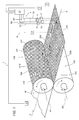
Figure 1 illustrates a packaging machine according to this invention in a schematic perspective view, partly in blocks and with some parts cut away for greater clarity; -
Figure 2 illustrates a portion of the embossing roller forming part of the machine ofFigure 1 , in a schematic plan view from above; -
Figure 3 illustrates a portion of the web of wrapping material processed in the machine ofFigure 1 , in a schematic plan view from above. - With reference to
Figure 1 , thenumeral 1 denotes a packaging machine according to this invention. - The
machine 1 is hereinafter described only insofar as necessary for understanding this invention. - The
machine 1 is designed to make packets, not illustrated, containing tobacco products such as cigarettes, for example. - The
machine 1 comprises forming means, of substantially known type and not described, for forming a wrapper for the tobacco products from a web W of wrapping material. - More specifically, the wrapper is the inner wrapper of a packet and the web W of wrapping material is, for example, a web of paper material or metallized paper, known as foil paper, or of metallic material such as, for example, aluminium foil or the like.
- The web W has a line of main extension D and advances in a feed direction V.
- The forming means basically comprise a system for unwinding the web W, schematically represented as a
block 3, a system for cutting the web into lengths, schematically represented as ablock 4, and a system for folding the lengths of wrapping material, schematically represented as a block 7. - The
machine 1 comprises a synchronizing system, denoted by thereference numeral 5, for synchronizing theunwinding system 3, thecutting system 4 and the folding system 7. - As will become clearer as this description continues, the synchronizing
system 5 is configured to identify a section of the web W based on the detection on the web W itself of areference 200 associated with that section, that is to say, areference 200 which defines a section of the web which controls the drive mechanism of thecutting system 4. - More specifically, the synchronizing
system 5 identifies a predetermined section of the web W, for example a transversal section thereof, based on the contrast between thereference 200 and the web W. - The forming means comprise an
embossing device 100 located along the feed path of the web W to imprint a permanent mark on the web W of wrapping material. - The
device 100 is of a substantially known type and is described only insofar as necessary for understanding this invention. - The
device 100 comprises afirst embossing roller 101 and asecond embossing roller 102 having respective axes of rotation R1 and R2. In the embodiment illustrated, with reference in particular toFigure 1 , it may be observed that theroller 101 rotates anticlockwise and theroller 102 clockwise. - The
roller 101 and theroller 102 are substantially cylindrical and the axes R1 and R2 are preferably parallel. - The
roller 101 and theroller 102 delimit apassage 103 for the web W and are positioned relative to each other in substantially known manner to emboss the web W as it passes between therollers passage 103. - In one embodiment, the
roller 101 comprises on itsouter surface 101 a, imprinting means 104 operating on the web W. - The imprinting means 104, as will become clearer as this description continues, are structured to imprint the
reference 200 on the web W. In one embodiment, the imprinting means 104 are structured to imprint adecorative pattern 205 on the web W. - The term "decorative pattern" 205 is used in this invention to mean any finish, design, text or the like which must appear on the inner wrapper of the cigarette packet.
- In the example illustrated, the
decorative pattern 205 comprises a rough-textured finish of the web W and the word "Pull" typically appearing on the inner wrappers of cigarette packets. - In the embodiment illustrated, the
roller 102 is an opposing roller acting in conjunction in substantially known manner with theroller 101 by means of itscylindrical surface 102a. - In an embodiment not illustrated in detail and known as pin up-pin up configuration, the
surface 101 a comprises a plurality of imprinting teeth and thesurface 102a comprises a plurality of imprinting teeth acting in conjunction with the imprinting teeth on thesurface 101 a. The teeth on the twosurfaces - In an embodiment not illustrated in detail and known as pin up-pin down configuration, the
surface 101 a comprises a plurality of imprinting teeth and thesurface 102a comprises a plurality of recesses for receiving the teeth of theroller 101. - As mentioned, the imprinting means 104 are structured to imprint the
reference 200 on the web. - With reference to
Figures 2 and 3 , in one embodiment, the imprinting means 104 comprise afirst toothing 106 having a first impression to imprint on said web W afirst segment 206 of thereference 200 according to a first pattern. - Preferably, in one embodiment, the
first segment 206 of thereference 200 is embossed on the web W. - In one embodiment, the
means 104 comprise asecond toothing 105 having a second impression to imprint the above mentioneddecorative pattern 205 on the web. - The
second toothing 105 comprises azone 108 without teeth for defining on the web W a second,unembossed segment 208 of thereference 200. - Preferably, the
zone 108 extends parallel to the axis R1 of theroller 101 and is made on thesurface 101 a of theroller 101 itself. - In practice, when the web W passes through the
passage 103, thezone 108 does not impress any pattern on it, leaving the web W substantially smooth. - As schematically illustrated, downstream of the
device 100, the web W has imprinted on it thedecorative pattern 205 whereas thesegment 208 is smooth, creating a contrast against thedecorative pattern 205. - As illustrated, the
first toothing 106 and thezone 108 without teeth are offset from each other along a directrix of thefirst roller 101. - In other words, the
first toothing 106 and thezone 108 lie on distinct directrices of theroller 101. - More specifically, the
first toothing 106 is located in such a way that the full length of it, measured along a generatrix of theroller 101, lies on afirst band 109 of directrices of theroller 101. - More specifically, the full length of the
zone 108, measured along a generatrix of theroller 101, lies on asecond band 110 of directrices of theroller 101. - Preferably, the
band 109 and theband 110 do not have any directrices of theroller 101 in common. - With reference in particular to
Figure 2 , it may be observed that the imprinting means 104 comprise athird toothing 111 having a third impression, preferably different to the impression of thetoothing 106, to imprint on the web W athird segment 211 of thereference 200 according to a second pattern, different to the above mentioned first pattern. - Preferably, in one embodiment, the
third segment 211 of thereference 200 is, in effect, embossed on the web W. - The
first toothing 106, thezone 108 without teeth and thethird toothing 111 are offset from each other along a directrix of theroller 101. - More specifically, the full length of the
zone 111, measured along a generatrix of theroller 101, lies on athird band 112 of directrices of theroller 101. - The
band 109, theband 110 and theband 112 do not have any directrices of theroller 101 in common. - In a preferred embodiment, the imprinting means 104 comprise a
fourth toothing 113 having a fourth impression, different to the impression of thetoothing 106 and to the impression of thetoothing 111 to imprint anembossed segment 213 on the web W. - The
first toothing 106, thezone 108 without teeth, thethird toothing 111 and thefourth toothing 113 are offset from each other along a directrix of theroller 101. - More specifically, the full length of the
zone 113, measured along a generatrix of theroller 101, lies on afourth band 114 of directrices of theroller 101. - The
band 109, theband 110, theband 112 and theband 114 do not have any directrices of theroller 101 in common. - The imprinting means 104 comprise a
fifth toothing 115 having a fifth impression, preferably the same as the impression of thetoothing 113, to imprint anembossed segment 215 on the web W. - The full length of the
zone 115, measured along a generatrix of theroller 101, lies on theband 114 of directrices of theroller 101. - The
toothing 113 and thetoothing 115 are spaced from each other along a directrix of theband 114 in such a way as to delimit azone 116 without teeth on theroller 101. - The
zone 116 lies in theband 114 and is aligned along a generatrix of theroller 101 with thetoothings zone 108. - The
zone 116 defines on the web W a fourth,unembossed segment 216, of thereference 200. - In light of the above, in one embodiment, the
reference 200 comprises thesegment 206, thesegment 208, thesegment 211 and thesegment 216 which are offset from each other along the main line of extension D. - More specifically, each
segment reference 200 identifies acorresponding strip - Each
strip segment 206, thesegment 208, thesegment 211 and thesegment 216 are aligned along a section of the web W at right angles to the line D. - In one embodiment, the imprinting means 104 comprise a
sixth toothing 117 to imprint on said web W acode 217 which identifies theembossing device 100. - In one embodiment, the
machine 1 comprises a reading sensor for each strip of the web W where there is a segment of thereference 200. - In the example illustrated in
Figure 1 , themachine 1 comprises asensor 6 for reading thestrip 206a, asensor 8 for reading thestrip 208a, asensor 11 for reading thestrip 211 a and asensor 16 for reading thestrip 216a. - The
first reading sensor 6 is configured to generate a first reading signal S1 depending on the reading contrast between thefirst segment 206 of thereference 200 and the web W. - The contrast between the
first segment 206 and the web W is read substantially as a step up or a step down depending on thepattern 205, if present, imprinted on the web W. - The
second reading sensor 8 is configured to generate a second reading signal S2 depending on the reading contrast between thesecond segment 208 of thereference 200 and the web W. - The contrast between the
second segment 208 and the web W is read, for example, substantially as a step up or a step down depending on thepattern 205, if present, imprinted on the web W. Thethird reading sensor 11 is configured to generate a third reading signal S3 depending on the reading contrast between thethird segment 211 of thereference 200 and the web W. - The contrast between the
third segment 211 and the web W is read, for example, substantially as a step up or a step down depending on thepattern 205, if present, imprinted on the web W. - The
fourth reading sensor 16 is configured to generate a fourth reading signal S4 depending on the reading contrast between thefourth segment 216 of thereference 200 and thesegment 213 and/or thesegment 215. - In the example illustrated, the
segment 215 is upstream of thesegment 216 along the web feed direction V and thesegment 213 is downstream of thesegment 216 along the web feed direction V. - The contrast between the
fourth segment 216 and thesegment 213 and/or 216 is read, for example, substantially as a step up or a step down. - For convenience of description, reference is made below, also for the
segment 216, to the contrast between the same and the web W and not to the contrast between it and the adjacentembossed segments segment 216 and thesegment 213 and/or 215 is implied. - The value of each of the aforementioned steps depends on the reading contrast for reading the respective segment of the
reference 200. - The
machine 1, and more specifically, theaforementioned synchronizing system 5, comprises acomputerized control unit 17 in communication with thesensors - The
computerized control unit 17 is configured to receive the signal S1, S2, S3, S4 and to identify the section of the web W based on the signal S1, or on the signal S2, or on the signal S3 or on the signal S4 depending on the reading contrast between therespective segment reference 200 and the web W. Advantageously, theunit 17 is configured to learn, in a learning step, which segment of thereference 200 has the highest reading contrast for the web W being processed and thepattern 205 imprinted thereon, and to base subsequent selections on the segment with the highest contrast. - Advantageously, a
device 100 as described above can be used to obtain areference 200 comprising a plurality ofsegments - By suitably selecting the patterns of the embossed segments of the
reference 200 and considering the presence of the unembossed segments, thereference 200 comprises at least one segment that will certainly be read, irrespective of the pattern on the web W. - In other words, given the
reference 200 composed of a plurality of segments having patterns which differ from each other and, thus, different contrasts against the web W, thecomputerized control unit 17 always has available a signal S1 or S2 or S3 or S4 which is determined by a contrast between the respective segment and the web W and which is sufficiently clear to precisely identify the web section allowing the cutting system to be synchronized. - In alternative embodiments, the
embossing device 100 comprises a plurality of toothings to imprint segments of thereference 200 which have different patterns in order to obtain a plurality of contrasts against the web W. - In one embodiment, the
reference 200 does not comprise segments which are substantially smooth, that is to say, it comprises only embossed segments obtained, for example, by means of toothings such as thetoothing - In practice, the
reference 200 constitutes a universal reference which can be used in all embossing rollers and which always allows obtaining a reference mark that can be interpreted with relative certainty for any web W, irrespective of the material or of the pattern imprinted thereon. - In one embodiment, the
computerized control unit 17 is configured to generate a difference signal between the first and second reading signals S1, S2 and to identify the section based on that difference signal. - In practice, for example, reading the
segment 206 and thesegment 208 generates the signals S1 and S2 which relate to an embossed segment and a smooth segment. - The difference between these two signals simulates a reading with the highest contrast as if it were a
reference 200 defined by an embossed segment on a smooth, unembossed band or strip. - In one embodiment, the
machine 1, and more specifically, the synchronizingsystem 5, comprises asensor 18 for identifying theroller 101 and in communication with thecomputerized control unit 17. - The
sensor 18 is configured to read theaforementioned identification code 217 and to generate a signal S identifying theembossing device 100. - The
computerized control unit 17 is configured to identify the section and to synchronize thecutting system 4 with the unwindingsystem 3 based on the signal S1 or the signal S2 or the signal S3 or the signal S4 depending on the identification signal S. - Once the
embossing device 100 mounted on themachine 1 has been recognized, that is to say, when the pattern imprinted on the web W has been recognized based on the signal S, thecomputerized control unit 17 is configured to select the signal S1 or S2 or S3 or S4 produced by the best reading contrast. - In practice, reading the
code 217 allows thecomputerized control unit 17 to learn which of the signals S1, S2, S3, S4 is the one produced by the best reading contrast and to select that signal to identify the section of the web W on the basis of which to drive, in particular, at least thesystem 3 for unwinding the web W, thecutting system 4 and the folding system 7. - In use, a method for identifying a section of the continuous web W comprises a step of defining on the web W, by means of embossing, a
reference 200 associated with that section so that identifying thereference 200 also identifies the section of the web W concerned. The method comprises a step of reading thereference 200 which, as mentioned, comprises for example,segments - The reference segments are offset from each other along the line D so that they can be read independently of each other.
- In one embodiment, the
reference 200 comprises theunembossed segment 116 located inside a sort of frame defined by the embossedsegments - In one embodiment, as mentioned, the step of reading the
reference 200 comprises reading all the segments of thereference 200 by means of therespective reading sensors - In one embodiment, the
code 217 is imprinted during the step of embossing the web W and the step of reading thereference 200 comprises a step of reading the code and all the segments of the reference. - As mentioned, the method comprises selecting from all the signals generated by the reading of the reference segments, the one corresponding to the best contrast based on the code of the
device 100. - In one embodiment, the method comprises identifying the reference segment expected to provide the best contrast against the web and positioning a reading sensor at that segment.
- In one embodiment, the method comprises identifying the reference segment expected to provide the best contrast against the web and, after positioning all the reading sensors to read all the segments, using only the sensor at the segment identified.
Claims (18)
- A method for identification of a section of a continuous web (W) having a main line of extension (D) and movable in a direction of feed (V) according to a predetermined path, said method comprising:a step of definition on said web (W) of a reference (200) associated with said section,a step of reading said reference (200) to identify said section using the contrast between said reference (200) and said web (W), said method being characterized in thatsaid step of definition of a reference (200) comprises a step of embossing said web (W) using an embossing device (100),said reference (200) comprising at least a first embossed segment (206) anda second unembossed segment (208), said first segment (206) having a contrast compared with said web (W) which is different to the contrast of said second segment (208) compared with said web (W), said first and second segments (206, 208) being positioned on said web (W) along respective strips (206a, 208a) parallel with said main line of extension (D),said method comprising a step of reading the reference (200) segment out of said first and second segments (206, 208) which has greatest reading contrast, said section being identified based on the segment having the greatest reading contrast.
- The method according to claim 1, wherein said embossing device (100) comprises a first embossing roller (101) and a second embossing roller (102) forming a passage (103) for a web (W) to be embossed, said first embossing roller (101) and said second embossing roller (102) being relatively positioned for embossing the web (W) passing through the passage (103), at least said first embossing roller (101) comprising on its outer surface (101 a) means for imprinting a reference on the web (W), the imprinting means comprising a first toothing (106) having a first impression and at least a second toothing (105) having a second impression, the second toothing (105) comprising a zone (108) without teeth;
said embossing step comprising imprinting said first segment (206) by means of said first toothing (106) according to a first pattern, imprinting a decorative pattern (205) by means of said second toothing (105) and defining said second segment (208) by means of the zone (108) without teeth. - The method according to claim 1 or 2, wherein said reference comprises at least a third, embossed segment (211), obtained in said embossing step, said third segment (211) having a contrast compared with said web (W) which is different to the contrast of the first and second segments (206, 208) compared with said web (W), said first, second and third segments (206, 208, 211) being positioned on the web (W) respectively along a first, a second and a third strip (206a, 208a, 211 a) each parallel with the main line of extension (D).
- The method according to any one of the preceding claims, wherein said reference comprises a fourth, unembossed segment (216) positioned on said web (W) along a respective fourth strip (216a) parallel with said main line of extension (D), said reference (200) comprising a fifth, embossed segment (213) aligned with said fourth segment (216) according to said main line of extension (D) and positioned downstream of said fourth segment (216) according to said direction of feed (V), said reference (200) comprising a sixth, embossed segment (215) aligned with said fourth segment (216) according to said main line of extension (D) and positioned upstream of said fourth segment (216) according to said direction of feed (V), said fifth and sixth segments (213, 215) being obtained in said embossing step.
- The method according to any one of the preceding claims, wherein at least said first segment (206) and said second segment (208) are aligned according to a reference line orthogonal relative to said main line of extension (D).
- The method according to any one of the preceding claims, wherein said reference (200) is defined on said web (W) together with said decorative pattern (205).
- The method according to any one of the preceding claims, wherein said step of reading said reference (200) comprises reading all of the segments (206, 208, 211, 216) of said reference (200) using a sensor (6, 8, 11, 16) for reading each segment (206, 208, 211, 216), the reading of said first segment (206) generating a first reading signal (S1), the reading of said second segment (208) generating a second reading signal (S2), the reading of said third segment (211) generating a third reading signal (S3), the reading of said fourth segment (216) generating a fourth reading signal (S4), each reading signal (S1, S2, S3, S4) being generated depending on the reading contrast of the respective reference segment (206, 208, 211, 216), said method comprising a step of selection from said first, second, third and fourth reading signals (S1, S2, S3, S4) of the reading signal expressing the greatest reading contrast for identifying said section.
- The method according to any one of the preceding claims, wherein said step of embossing said web (W) comprises imprinting on said web a code (217) for identifying said embossing device (100), said step of reading said reference comprising reading of said identification code using an identification sensor (18) and all of the segments (206, 208, 211, 216) of said reference (200) using a reading sensor (6, 8, 11, 16) for each segment, the reading of said identification code generating an identification signal (S) for said embossing device, the reading of said first segment (206) generating a first reading signal (S1), the reading of said second segment (208) generating a second reading signal (S2), the reading of said third segment (211) generating a third reading signal (S3), the reading of said fourth segment (216) generating a fourth reading signal (S4), each reading signal (S1, S2, S3, S4) being generated depending on the reading contrast of the respective reference segment (206, 208, 211, 216),
said method comprising a step of selection, to identify said section, of the first reading signal (S1) or of the second reading signal (S2) or of the third reading signal (S3) or of the fourth reading signal (S4) depending on said embossing device identification signal (S). - The method according to any one of the preceding claims, wherein said step of reading said reference (200) comprises selection of the segment amongst said first segment (206), said second segment (208), said third segment (211) or said fourth segment (216) of said reference having the greatest reading contrast compared with the web relative to the others, positioning a reading sensor (6, 8, 11, 16) for reading the selected segment, identifying said section based on the reading of the selected segment.
- An embossing device (100) comprising a first embossing roller (101) and a second embossing roller (102) which form a passage (103) for a web (W) of wrapping material to be embossed, said web (W) having a main line of extension (D) and a direction of feed (V), said first embossing roller (101) and said second embossing roller (102) being positioned relative to each other for embossing said web (W) as it goes through the passage (103), at least said first embossing roller (101) comprising on its outer surface (101 a) means to imprint a reference (200) on said web (W) for identifying a section of said web (W), said device (100) being characterized in that
said imprinting means comprise a first toothing (106) having a first impression to imprint on said web a first segment (206) of said reference (200) according to a first pattern;
at least a second toothing (105) having a second impression to imprint a decorative pattern (205) on said web, said second toothing (105) comprising a zone (108) without teeth for defining on said web a second, unembossed segment (208) of said reference (200), said first toothing (106) lying on a first band (109) of directrices of said first roller (101) and said zone (108) lying on a second band (110) of directrices of said first roller (101). - The device according to claim 10, wherein said imprinting means comprise at least a third toothing (111) having a third impression to imprint on said web a third segment (211) of said reference (200) according to a third pattern, said third toothing (111) lying on a third band (112) of directrices of said first roller (101).
- The device according to claim 10 or 11, wherein said imprinting means comprise
a fourth toothing (113) having a fourth impression to imprint on said web a fifth, embossed segment (213);
a fifth toothing (115) having a fifth impression to imprint on said web a sixth, embossed segment (215);
said fourth and fifth toothings (113, 115) being aligned according to a directrix of said first roller (101) and delimiting a second zone (116) without teeth along said directrix for defining on said web a fourth, unembossed segment (216) of said reference (200),
said fourth and fifth toothings (113, 115) and said second zone (116) without teeth lying on a fourth band (114) of directrices of said first roller (101). - The device according to any one of claims 10 to 12, wherein said first toothing (106) and/or said third toothing (111) and/or said first zone (108) without teeth and/or said second zone (116) without teeth are aligned according to a generatrix of said first roller (101).
- The embossing device according to any one of claims 10 to 13, wherein said imprinting means comprise a sixth toothing (117) to imprint an identification code (217) for said embossing device on said web (W).
- A packaging machine for making packets comprising smokers' articles, said packaging machine comprising means (3, 4, 7, 100) for forming a wrapper for said smokers' articles starting from a web (W) of packaging material, said forming means (3, 4, 7, 100) comprising a system (3) for unwinding the web (W), a system (4) for cutting the web (W) and an embossing device (100) for said packaging material, said machine comprising a synchronization system (5) at least for said unwinding system (3) and said cutting system (4),
said packaging machine being characterized in that said embossing device (100) is of the type according to any one of claims 10 to 14, said synchronization system (5) being designed to synchronize said unwinding system (3) and said cutting system (4) depending on the position of said section identified by means of said reference (200). - The packaging machine according to claim 15, wherein said synchronization system (5) comprises at least a first and a second reading sensor (6, 8) respectively for reading said first segment (206) of said reference and said second segment (208) of said reference (200),
said first reading sensor being designed to generate a first reading signal (S1) depending on the reading contrast between said first segment of said reference and said web,
said second reading sensor being designed to generate a second reading signal (S2) depending on the reading contrast between said second segment of said reference and said web,
said synchronization system (5) comprising a computerized control unit (17) in communication with said first and second reading sensors (6, 8) and designed to receive said first and second reading signals (S1, S2) said computerized control unit (17) being designed to identify said section based on the first reading signal (S1) or on the second reading signal (S2) depending on the reading contrast between the respective segment (206, 208) of the reference and said web (W). - The machine according to claim 16, wherein said synchronization system comprises a sensor (18) for identifying said embossing device (100) in communication with said computerized control unit (17) and designed to read said identification code (217), said identification sensor (18) generating an identification signal (S) for said embossing device (100),
said computerized control unit (17) being designed to identify said section based on the first reading signal (S1) or on the second reading signal (S2) depending on said identification signal (S). - The packaging machine according to claim 15, wherein said synchronization system (5) comprises at least a first and a second reading sensor (6, 8) respectively for reading said first segment (206) of said reference and said second segment (208) of said reference (200),
said first reading sensor being designed to generate a first reading signal (S1) depending on the reading contrast between said first segment of said reference and said web,
said second reading sensor being designed to generate a second reading signal (S2) depending on the reading contrast between said second segment of said reference and said web,
said synchronization system (5) comprising a computerized control unit (17) in communication with said first and second reading sensors (6, 8) and designed to receive said first and second reading signals (S1, S2) said computerized control unit (17) being designed to generate a difference signal between said first and second reading signals (S1, S2) and to identify said section based on said difference signal.
Applications Claiming Priority (1)
| Application Number | Priority Date | Filing Date | Title |
|---|---|---|---|
| IT000392A ITBO20130392A1 (en) | 2013-07-23 | 2013-07-23 | EMBOSSING DEVICE, PACKING MACHINE INCLUDING THIS DEVICE |
Publications (2)
| Publication Number | Publication Date |
|---|---|
| EP2829393A1 true EP2829393A1 (en) | 2015-01-28 |
| EP2829393B1 EP2829393B1 (en) | 2021-09-01 |
Family
ID=49261601
Family Applications (1)
| Application Number | Title | Priority Date | Filing Date |
|---|---|---|---|
| EP14178021.3A Active EP2829393B1 (en) | 2013-07-23 | 2014-07-22 | Method for identification of a section of a continuous web and embossing device |
Country Status (4)
| Country | Link |
|---|---|
| US (1) | US9751648B2 (en) |
| EP (1) | EP2829393B1 (en) |
| IT (1) | ITBO20130392A1 (en) |
| RU (1) | RU2652578C2 (en) |
Families Citing this family (5)
| Publication number | Priority date | Publication date | Assignee | Title |
|---|---|---|---|---|
| PL2838721T4 (en) * | 2012-04-17 | 2023-02-20 | Boegli-Gravures S.A. | Method for manufacturing a set of embossing rollers |
| EP3184292A1 (en) * | 2015-12-22 | 2017-06-28 | Boegli-Gravures S.A. | Device for fine embossing of packaging materials with a set of embossing rollers of the male-female die type |
| EP3300612A1 (en) * | 2016-10-03 | 2018-04-04 | Boegli-Gravures S.A. | Paper joint without discontinuity for tube shaped paper wraps closed by means of embossed paper and re-sealable innerliner seal by means of structured innerliner |
| NL2018973B1 (en) * | 2017-05-24 | 2018-12-07 | Vmi Holland Bv | Apparatus for marking batches and a system and method for marking batches and/or processing said marked batches |
| CN112440520A (en) * | 2020-11-28 | 2021-03-05 | 龙港市鑫鑫印刷机械有限公司 | Rubber clamp of rubber roller of circular embossing machine |
Citations (5)
| Publication number | Priority date | Publication date | Assignee | Title |
|---|---|---|---|---|
| EP1867470A1 (en) * | 2006-06-15 | 2007-12-19 | Boegli-Gravures S.A. | Method and device for the authentication of identification marks on a packaging foil or package |
| DE102008013322A1 (en) * | 2007-03-30 | 2008-10-02 | Heidelberger Druckmaschinen Ag | Printing unit of a substrate processing machine |
| WO2008134910A1 (en) * | 2007-05-04 | 2008-11-13 | Boegli-Gravures S.A. | Method and device for the recognition of an authenticating mark on an enveloped surface of an object |
| EP2468493A1 (en) * | 2010-12-23 | 2012-06-27 | Boegli-Gravures S.A. | Device for embossing films |
| EP2511088A1 (en) * | 2011-04-12 | 2012-10-17 | Boegli-Gravures S.A. | Method and device for producing a package for tobacco articles |
Family Cites Families (31)
| Publication number | Priority date | Publication date | Assignee | Title |
|---|---|---|---|---|
| US5768760A (en) * | 1995-10-31 | 1998-06-23 | Nynex Science & Technology, Inc. | System and method for automatically processing coin collection boxes |
| US5715658A (en) * | 1995-11-15 | 1998-02-10 | Nynex Science & Technology, Inc. | System and method for automatically processing coin collection boxes |
| US6317648B1 (en) * | 1996-09-06 | 2001-11-13 | Merck & Co., Inc. | Customer specific packaging line having containers with tag means containing medication order information |
| JP3710913B2 (en) * | 1997-05-19 | 2005-10-26 | 富士写真フイルム株式会社 | Packaging system for goods |
| NL1014000C2 (en) * | 1999-12-31 | 2001-07-09 | Neopost Bv | Method and device for assembling mail items with selective envelope selection. |
| US20020026768A1 (en) * | 2000-02-01 | 2002-03-07 | Duncan Gregory Scott | Order builder |
| JP3926149B2 (en) * | 2001-12-25 | 2007-06-06 | 富士フイルム株式会社 | Automatic packaging method and system for rolls |
| EP1352830B1 (en) * | 2002-04-09 | 2004-11-03 | Fuji Photo Film Co., Ltd. | method of and apparatus for automatically packaging products |
| US20050198920A1 (en) * | 2002-08-07 | 2005-09-15 | Yukio Nakagawa | Packaging material roll, packing machine using the roll, and commercial goods processing system with the machine |
| US6892512B2 (en) * | 2002-08-07 | 2005-05-17 | Medco Health Solutions, Inc. | Automated prescription filling system/method with automated labeling and packaging system/method automated order consolidation system/method |
| US20090166238A1 (en) * | 2004-03-18 | 2009-07-02 | Dickinson Kent H | Shipping container |
| US8141330B2 (en) * | 2004-05-20 | 2012-03-27 | KNAPP Logistics Automation, Inc. | Systems and methods of automated tablet dispensing, prescription filling, and packaging |
| CA2493410C (en) * | 2005-01-20 | 2016-09-27 | Intelligent Devices Inc. | Assembly, production and quality assurance processes respecting electronic compliance monitor (ecm) tags |
| US7765776B1 (en) * | 2006-10-19 | 2010-08-03 | Medco Health Solutions, Inc. | Systems and methods for dispensing pharmaceutical/medical product and branding pharmaceutical/medical containers |
| FR2907424B1 (en) * | 2006-10-19 | 2012-09-21 | Edixia | METHOD AND DEVICE FOR PROVIDING PACKAGING MONITORING AND MARKING |
| US20080169044A1 (en) * | 2006-10-20 | 2008-07-17 | Forhealth Technologies, Inc. | Automated drug preparation apparatus including syringe loading, preparation and filling |
| US7814731B2 (en) * | 2006-10-20 | 2010-10-19 | Forhealth Technologies, Inc. | Automated drug preparation apparatus including a bluetooth communications network |
| US7900658B2 (en) * | 2006-10-20 | 2011-03-08 | Fht, Inc. | Automated drug preparation apparatus including drug vial handling, venting, cannula positioning functionality |
| US7779614B1 (en) * | 2007-05-30 | 2010-08-24 | Walgreen Co. | Method of loading a multi-dose blister card using intermediate blister cards |
| US8474228B2 (en) * | 2009-12-08 | 2013-07-02 | Life Technologies Corporation | Packaging systems and methods for transporting vials |
| US8943785B2 (en) * | 2009-08-20 | 2015-02-03 | Pioneer Hi Bred International Inc | Automated high-throughput seed processing apparatus |
| US9333541B2 (en) * | 2010-03-01 | 2016-05-10 | Yuyama Mfg. Co., Ltd. | Powder removal device of medicine dispenser |
| DE102010024548A1 (en) * | 2010-06-22 | 2011-12-22 | Multivac Sepp Haggenmüller Gmbh & Co. Kg | Packaging system for filling a collection container with articles |
| US10695490B2 (en) * | 2010-09-17 | 2020-06-30 | Nicholas J Perazzo | Syringe filling and packaging system for hospital pharmacies |
| US9466088B2 (en) * | 2010-09-17 | 2016-10-11 | National Instrument, Llc | Automated oral syringe packaging system for hospital pharmacies |
| PL2465780T3 (en) * | 2010-12-16 | 2013-10-31 | Inversiones Hiki6 S L | Mobile dosing, mixing and packaging plant |
| US9436770B2 (en) * | 2011-03-10 | 2016-09-06 | Fastechnology Group, LLC | Database systems and methods for consumer packaged goods |
| US9073206B2 (en) * | 2012-06-21 | 2015-07-07 | Omnicare, Inc. | Methods and apparatus for automated filling of packagings with medications |
| CA3018688C (en) * | 2011-10-24 | 2020-02-11 | Remedi Technology Holdings, Llc | Packaging system for pharmaceutical dispenser and associated method |
| US20140069838A1 (en) * | 2012-04-16 | 2014-03-13 | Eugenio Minvielle | Nutritional Substance Label System For Adaptive Conditioning |
| US20150272824A1 (en) * | 2014-03-25 | 2015-10-01 | Aesynt | Apparatuses, systems, and methods for product packaging |
-
2013
- 2013-07-23 IT IT000392A patent/ITBO20130392A1/en unknown
-
2014
- 2014-07-15 RU RU2014128909A patent/RU2652578C2/en not_active IP Right Cessation
- 2014-07-21 US US14/336,121 patent/US9751648B2/en not_active Expired - Fee Related
- 2014-07-22 EP EP14178021.3A patent/EP2829393B1/en active Active
Patent Citations (5)
| Publication number | Priority date | Publication date | Assignee | Title |
|---|---|---|---|---|
| EP1867470A1 (en) * | 2006-06-15 | 2007-12-19 | Boegli-Gravures S.A. | Method and device for the authentication of identification marks on a packaging foil or package |
| DE102008013322A1 (en) * | 2007-03-30 | 2008-10-02 | Heidelberger Druckmaschinen Ag | Printing unit of a substrate processing machine |
| WO2008134910A1 (en) * | 2007-05-04 | 2008-11-13 | Boegli-Gravures S.A. | Method and device for the recognition of an authenticating mark on an enveloped surface of an object |
| EP2468493A1 (en) * | 2010-12-23 | 2012-06-27 | Boegli-Gravures S.A. | Device for embossing films |
| EP2511088A1 (en) * | 2011-04-12 | 2012-10-17 | Boegli-Gravures S.A. | Method and device for producing a package for tobacco articles |
Also Published As
| Publication number | Publication date |
|---|---|
| ITBO20130392A1 (en) | 2015-01-24 |
| RU2014128909A (en) | 2016-02-10 |
| US20150027083A1 (en) | 2015-01-29 |
| EP2829393B1 (en) | 2021-09-01 |
| RU2652578C2 (en) | 2018-04-26 |
| US9751648B2 (en) | 2017-09-05 |
Similar Documents
| Publication | Publication Date | Title |
|---|---|---|
| EP2829393B1 (en) | Method for identification of a section of a continuous web and embossing device | |
| EP2697052B1 (en) | Method and device for producing a package for smoking articles | |
| RU2483874C2 (en) | Device composed of packing foil processing rollers and method of preparing packing foil for packing | |
| EP1867470B1 (en) | Method and device for the authentication of identification marks on a packaging foil or package | |
| RU2471629C2 (en) | Device and method of making embossed paper or laminated metallic foil | |
| US10231478B2 (en) | Apparatus and method for making a smoking article | |
| US7147453B2 (en) | Device for treating flat material | |
| US9492966B2 (en) | Method for embossing a tip cover of a cigarette tip | |
| CN102459005B (en) | Device for embossing in particular the collar of a hinged-lid pack for cigarettes | |
| CN103072315B (en) | For utilizing the method rotating imprinting apparatus impressing product | |
| EP2832535B1 (en) | Embossing device | |
| ITBO20000069A1 (en) | METHOD FOR THE REALIZATION OF WRAPPING MATERIAL TO BE USED FOR THE REALIZATION OF SMOKE ITEMS. | |
| JP6167171B2 (en) | Method and apparatus for the production of a plurality of blanks, especially for cigarette packages | |
| WO2019244003A1 (en) | Method for processing a web of wrapping material used to make smoking articles | |
| ITBO20130391A1 (en) | EMBOSSING DEVICE, PACKING MACHINE INCLUDING THIS DEVICE | |
| ITMI20010140A1 (en) | METHOD AND EQUIPMENT FOR THE PRODUCTION OF PAPER SHEETS PROVIDED WITH PREFIXED DIAGRAM MARKING ELEMENTS IN WHICH G | |
| ITPI20070047A1 (en) | PACKAGING METHOD OF CUTS MANUFACTURED PRODUCTS, PACKAGING MACHINE FOR CUTS AND RELATED PRODUCT |
Legal Events
| Date | Code | Title | Description |
|---|---|---|---|
| 17P | Request for examination filed |
Effective date: 20140722 |
|
| AK | Designated contracting states |
Kind code of ref document: A1 Designated state(s): AL AT BE BG CH CY CZ DE DK EE ES FI FR GB GR HR HU IE IS IT LI LT LU LV MC MK MT NL NO PL PT RO RS SE SI SK SM TR |
|
| AX | Request for extension of the european patent |
Extension state: BA ME |
|
| PUAI | Public reference made under article 153(3) epc to a published international application that has entered the european phase |
Free format text: ORIGINAL CODE: 0009012 |
|
| R17P | Request for examination filed (corrected) |
Effective date: 20150728 |
|
| RBV | Designated contracting states (corrected) |
Designated state(s): AL AT BE BG CH CY CZ DE DK EE ES FI FR GB GR HR HU IE IS IT LI LT LU LV MC MK MT NL NO PL PT RO RS SE SI SK SM TR |
|
| STAA | Information on the status of an ep patent application or granted ep patent |
Free format text: STATUS: EXAMINATION IS IN PROGRESS |
|
| 17Q | First examination report despatched |
Effective date: 20180126 |
|
| STAA | Information on the status of an ep patent application or granted ep patent |
Free format text: STATUS: EXAMINATION IS IN PROGRESS |
|
| GRAP | Despatch of communication of intention to grant a patent |
Free format text: ORIGINAL CODE: EPIDOSNIGR1 |
|
| STAA | Information on the status of an ep patent application or granted ep patent |
Free format text: STATUS: GRANT OF PATENT IS INTENDED |
|
| INTG | Intention to grant announced |
Effective date: 20210223 |
|
| GRAS | Grant fee paid |
Free format text: ORIGINAL CODE: EPIDOSNIGR3 |
|
| GRAA | (expected) grant |
Free format text: ORIGINAL CODE: 0009210 |
|
| STAA | Information on the status of an ep patent application or granted ep patent |
Free format text: STATUS: THE PATENT HAS BEEN GRANTED |
|
| AK | Designated contracting states |
Kind code of ref document: B1 Designated state(s): AL AT BE BG CH CY CZ DE DK EE ES FI FR GB GR HR HU IE IS IT LI LT LU LV MC MK MT NL NO PL PT RO RS SE SI SK SM TR |
|
| REG | Reference to a national code |
Ref country code: GB Ref legal event code: FG4D |
|
| REG | Reference to a national code |
Ref country code: CH Ref legal event code: EP Ref country code: AT Ref legal event code: REF Ref document number: 1425802 Country of ref document: AT Kind code of ref document: T Effective date: 20210915 |
|
| REG | Reference to a national code |
Ref country code: DE Ref legal event code: R096 Ref document number: 602014079803 Country of ref document: DE |
|
| REG | Reference to a national code |
Ref country code: IE Ref legal event code: FG4D |
|
| REG | Reference to a national code |
Ref country code: LT Ref legal event code: MG9D |
|
| REG | Reference to a national code |
Ref country code: NL Ref legal event code: MP Effective date: 20210901 |
|
| PG25 | Lapsed in a contracting state [announced via postgrant information from national office to epo] |
Ref country code: BG Free format text: LAPSE BECAUSE OF FAILURE TO SUBMIT A TRANSLATION OF THE DESCRIPTION OR TO PAY THE FEE WITHIN THE PRESCRIBED TIME-LIMIT Effective date: 20211201 Ref country code: LT Free format text: LAPSE BECAUSE OF FAILURE TO SUBMIT A TRANSLATION OF THE DESCRIPTION OR TO PAY THE FEE WITHIN THE PRESCRIBED TIME-LIMIT Effective date: 20210901 Ref country code: FI Free format text: LAPSE BECAUSE OF FAILURE TO SUBMIT A TRANSLATION OF THE DESCRIPTION OR TO PAY THE FEE WITHIN THE PRESCRIBED TIME-LIMIT Effective date: 20210901 Ref country code: ES Free format text: LAPSE BECAUSE OF FAILURE TO SUBMIT A TRANSLATION OF THE DESCRIPTION OR TO PAY THE FEE WITHIN THE PRESCRIBED TIME-LIMIT Effective date: 20210901 Ref country code: NO Free format text: LAPSE BECAUSE OF FAILURE TO SUBMIT A TRANSLATION OF THE DESCRIPTION OR TO PAY THE FEE WITHIN THE PRESCRIBED TIME-LIMIT Effective date: 20211201 Ref country code: HR Free format text: LAPSE BECAUSE OF FAILURE TO SUBMIT A TRANSLATION OF THE DESCRIPTION OR TO PAY THE FEE WITHIN THE PRESCRIBED TIME-LIMIT Effective date: 20210901 Ref country code: RS Free format text: LAPSE BECAUSE OF FAILURE TO SUBMIT A TRANSLATION OF THE DESCRIPTION OR TO PAY THE FEE WITHIN THE PRESCRIBED TIME-LIMIT Effective date: 20210901 Ref country code: SE Free format text: LAPSE BECAUSE OF FAILURE TO SUBMIT A TRANSLATION OF THE DESCRIPTION OR TO PAY THE FEE WITHIN THE PRESCRIBED TIME-LIMIT Effective date: 20210901 |
|
| REG | Reference to a national code |
Ref country code: AT Ref legal event code: MK05 Ref document number: 1425802 Country of ref document: AT Kind code of ref document: T Effective date: 20210901 |
|
| PG25 | Lapsed in a contracting state [announced via postgrant information from national office to epo] |
Ref country code: PL Free format text: LAPSE BECAUSE OF FAILURE TO SUBMIT A TRANSLATION OF THE DESCRIPTION OR TO PAY THE FEE WITHIN THE PRESCRIBED TIME-LIMIT Effective date: 20210901 Ref country code: LV Free format text: LAPSE BECAUSE OF FAILURE TO SUBMIT A TRANSLATION OF THE DESCRIPTION OR TO PAY THE FEE WITHIN THE PRESCRIBED TIME-LIMIT Effective date: 20210901 Ref country code: GR Free format text: LAPSE BECAUSE OF FAILURE TO SUBMIT A TRANSLATION OF THE DESCRIPTION OR TO PAY THE FEE WITHIN THE PRESCRIBED TIME-LIMIT Effective date: 20211202 |
|
| PG25 | Lapsed in a contracting state [announced via postgrant information from national office to epo] |
Ref country code: AT Free format text: LAPSE BECAUSE OF FAILURE TO SUBMIT A TRANSLATION OF THE DESCRIPTION OR TO PAY THE FEE WITHIN THE PRESCRIBED TIME-LIMIT Effective date: 20210901 |
|
| PG25 | Lapsed in a contracting state [announced via postgrant information from national office to epo] |
Ref country code: IS Free format text: LAPSE BECAUSE OF FAILURE TO SUBMIT A TRANSLATION OF THE DESCRIPTION OR TO PAY THE FEE WITHIN THE PRESCRIBED TIME-LIMIT Effective date: 20220101 Ref country code: SM Free format text: LAPSE BECAUSE OF FAILURE TO SUBMIT A TRANSLATION OF THE DESCRIPTION OR TO PAY THE FEE WITHIN THE PRESCRIBED TIME-LIMIT Effective date: 20210901 Ref country code: SK Free format text: LAPSE BECAUSE OF FAILURE TO SUBMIT A TRANSLATION OF THE DESCRIPTION OR TO PAY THE FEE WITHIN THE PRESCRIBED TIME-LIMIT Effective date: 20210901 Ref country code: RO Free format text: LAPSE BECAUSE OF FAILURE TO SUBMIT A TRANSLATION OF THE DESCRIPTION OR TO PAY THE FEE WITHIN THE PRESCRIBED TIME-LIMIT Effective date: 20210901 Ref country code: PT Free format text: LAPSE BECAUSE OF FAILURE TO SUBMIT A TRANSLATION OF THE DESCRIPTION OR TO PAY THE FEE WITHIN THE PRESCRIBED TIME-LIMIT Effective date: 20220103 Ref country code: NL Free format text: LAPSE BECAUSE OF FAILURE TO SUBMIT A TRANSLATION OF THE DESCRIPTION OR TO PAY THE FEE WITHIN THE PRESCRIBED TIME-LIMIT Effective date: 20210901 Ref country code: EE Free format text: LAPSE BECAUSE OF FAILURE TO SUBMIT A TRANSLATION OF THE DESCRIPTION OR TO PAY THE FEE WITHIN THE PRESCRIBED TIME-LIMIT Effective date: 20210901 Ref country code: CZ Free format text: LAPSE BECAUSE OF FAILURE TO SUBMIT A TRANSLATION OF THE DESCRIPTION OR TO PAY THE FEE WITHIN THE PRESCRIBED TIME-LIMIT Effective date: 20210901 Ref country code: AL Free format text: LAPSE BECAUSE OF FAILURE TO SUBMIT A TRANSLATION OF THE DESCRIPTION OR TO PAY THE FEE WITHIN THE PRESCRIBED TIME-LIMIT Effective date: 20210901 |
|
| REG | Reference to a national code |
Ref country code: DE Ref legal event code: R097 Ref document number: 602014079803 Country of ref document: DE |
|
| PLBE | No opposition filed within time limit |
Free format text: ORIGINAL CODE: 0009261 |
|
| STAA | Information on the status of an ep patent application or granted ep patent |
Free format text: STATUS: NO OPPOSITION FILED WITHIN TIME LIMIT |
|
| PG25 | Lapsed in a contracting state [announced via postgrant information from national office to epo] |
Ref country code: IT Free format text: LAPSE BECAUSE OF FAILURE TO SUBMIT A TRANSLATION OF THE DESCRIPTION OR TO PAY THE FEE WITHIN THE PRESCRIBED TIME-LIMIT Effective date: 20210901 Ref country code: DK Free format text: LAPSE BECAUSE OF FAILURE TO SUBMIT A TRANSLATION OF THE DESCRIPTION OR TO PAY THE FEE WITHIN THE PRESCRIBED TIME-LIMIT Effective date: 20210901 |
|
| 26N | No opposition filed |
Effective date: 20220602 |
|
| PG25 | Lapsed in a contracting state [announced via postgrant information from national office to epo] |
Ref country code: SI Free format text: LAPSE BECAUSE OF FAILURE TO SUBMIT A TRANSLATION OF THE DESCRIPTION OR TO PAY THE FEE WITHIN THE PRESCRIBED TIME-LIMIT Effective date: 20210901 |
|
| REG | Reference to a national code |
Ref country code: DE Ref legal event code: R119 Ref document number: 602014079803 Country of ref document: DE |
|
| PG25 | Lapsed in a contracting state [announced via postgrant information from national office to epo] |
Ref country code: MC Free format text: LAPSE BECAUSE OF FAILURE TO SUBMIT A TRANSLATION OF THE DESCRIPTION OR TO PAY THE FEE WITHIN THE PRESCRIBED TIME-LIMIT Effective date: 20210901 |
|
| REG | Reference to a national code |
Ref country code: CH Ref legal event code: PL |
|
| GBPC | Gb: european patent ceased through non-payment of renewal fee |
Effective date: 20220722 |
|
| REG | Reference to a national code |
Ref country code: BE Ref legal event code: MM Effective date: 20220731 |
|
| PG25 | Lapsed in a contracting state [announced via postgrant information from national office to epo] |
Ref country code: LU Free format text: LAPSE BECAUSE OF NON-PAYMENT OF DUE FEES Effective date: 20220722 Ref country code: LI Free format text: LAPSE BECAUSE OF NON-PAYMENT OF DUE FEES Effective date: 20220731 Ref country code: FR Free format text: LAPSE BECAUSE OF NON-PAYMENT OF DUE FEES Effective date: 20220731 Ref country code: CH Free format text: LAPSE BECAUSE OF NON-PAYMENT OF DUE FEES Effective date: 20220731 |
|
| PG25 | Lapsed in a contracting state [announced via postgrant information from national office to epo] |
Ref country code: GB Free format text: LAPSE BECAUSE OF NON-PAYMENT OF DUE FEES Effective date: 20220722 Ref country code: DE Free format text: LAPSE BECAUSE OF NON-PAYMENT OF DUE FEES Effective date: 20230201 Ref country code: BE Free format text: LAPSE BECAUSE OF NON-PAYMENT OF DUE FEES Effective date: 20220731 |
|
| PG25 | Lapsed in a contracting state [announced via postgrant information from national office to epo] |
Ref country code: IE Free format text: LAPSE BECAUSE OF NON-PAYMENT OF DUE FEES Effective date: 20220722 |
|
| PG25 | Lapsed in a contracting state [announced via postgrant information from national office to epo] |
Ref country code: HU Free format text: LAPSE BECAUSE OF FAILURE TO SUBMIT A TRANSLATION OF THE DESCRIPTION OR TO PAY THE FEE WITHIN THE PRESCRIBED TIME-LIMIT; INVALID AB INITIO Effective date: 20140722 |