EP2829249A1 - Ablation electrode and perfusion electrode catheter using same - Google Patents
Ablation electrode and perfusion electrode catheter using same Download PDFInfo
- Publication number
- EP2829249A1 EP2829249A1 EP13765068.5A EP13765068A EP2829249A1 EP 2829249 A1 EP2829249 A1 EP 2829249A1 EP 13765068 A EP13765068 A EP 13765068A EP 2829249 A1 EP2829249 A1 EP 2829249A1
- Authority
- EP
- European Patent Office
- Prior art keywords
- hole
- electrode
- insert
- temperature sensor
- distal end
- Prior art date
- Legal status (The legal status is an assumption and is not a legal conclusion. Google has not performed a legal analysis and makes no representation as to the accuracy of the status listed.)
- Ceased
Links
- 238000002679 ablation Methods 0.000 title claims abstract description 96
- 230000010412 perfusion Effects 0.000 title claims abstract description 61
- 239000007788 liquid Substances 0.000 claims abstract description 72
- 238000009413 insulation Methods 0.000 claims description 74
- 239000002861 polymer material Substances 0.000 claims description 9
- 239000000919 ceramic Substances 0.000 claims description 6
- 230000000149 penetrating effect Effects 0.000 claims description 6
- 238000010276 construction Methods 0.000 claims description 5
- 238000000034 method Methods 0.000 abstract description 10
- 230000037361 pathway Effects 0.000 abstract 3
- 238000002955 isolation Methods 0.000 abstract 1
- 230000000630 rising effect Effects 0.000 abstract 1
- 239000000463 material Substances 0.000 description 25
- 239000007769 metal material Substances 0.000 description 13
- 230000000694 effects Effects 0.000 description 12
- 210000001519 tissue Anatomy 0.000 description 10
- 238000003466 welding Methods 0.000 description 10
- 238000004026 adhesive bonding Methods 0.000 description 8
- 238000001816 cooling Methods 0.000 description 7
- 238000010586 diagram Methods 0.000 description 6
- 229910001220 stainless steel Inorganic materials 0.000 description 6
- 230000001681 protective effect Effects 0.000 description 5
- 239000010935 stainless steel Substances 0.000 description 5
- 210000004369 blood Anatomy 0.000 description 4
- 239000008280 blood Substances 0.000 description 4
- 238000010438 heat treatment Methods 0.000 description 4
- 239000002184 metal Substances 0.000 description 4
- 229910052751 metal Inorganic materials 0.000 description 4
- 208000027418 Wounds and injury Diseases 0.000 description 3
- 230000006378 damage Effects 0.000 description 3
- 239000003292 glue Substances 0.000 description 3
- 208000014674 injury Diseases 0.000 description 3
- 230000002787 reinforcement Effects 0.000 description 3
- 239000004677 Nylon Substances 0.000 description 2
- 229920002614 Polyether block amide Polymers 0.000 description 2
- 239000004642 Polyimide Substances 0.000 description 2
- FAPWRFPIFSIZLT-UHFFFAOYSA-M Sodium chloride Chemical compound [Na+].[Cl-] FAPWRFPIFSIZLT-UHFFFAOYSA-M 0.000 description 2
- 230000002159 abnormal effect Effects 0.000 description 2
- 239000000853 adhesive Substances 0.000 description 2
- 230000001070 adhesive effect Effects 0.000 description 2
- 230000023555 blood coagulation Effects 0.000 description 2
- 210000005242 cardiac chamber Anatomy 0.000 description 2
- 239000004020 conductor Substances 0.000 description 2
- 210000005003 heart tissue Anatomy 0.000 description 2
- 238000003754 machining Methods 0.000 description 2
- 229920001778 nylon Polymers 0.000 description 2
- 229920001721 polyimide Polymers 0.000 description 2
- 239000004814 polyurethane Substances 0.000 description 2
- 229920002635 polyurethane Polymers 0.000 description 2
- 239000011148 porous material Substances 0.000 description 2
- 102000004506 Blood Proteins Human genes 0.000 description 1
- 108010017384 Blood Proteins Proteins 0.000 description 1
- 239000004952 Polyamide Substances 0.000 description 1
- 238000010317 ablation therapy Methods 0.000 description 1
- 210000001367 artery Anatomy 0.000 description 1
- 239000000560 biocompatible material Substances 0.000 description 1
- 239000012620 biological material Substances 0.000 description 1
- 230000000903 blocking effect Effects 0.000 description 1
- 230000018044 dehydration Effects 0.000 description 1
- 238000006297 dehydration reaction Methods 0.000 description 1
- 238000009826 distribution Methods 0.000 description 1
- 238000001125 extrusion Methods 0.000 description 1
- 210000003191 femoral vein Anatomy 0.000 description 1
- 239000010408 film Substances 0.000 description 1
- 239000011810 insulating material Substances 0.000 description 1
- 239000012774 insulation material Substances 0.000 description 1
- 238000012806 monitoring device Methods 0.000 description 1
- 229910001000 nickel titanium Inorganic materials 0.000 description 1
- 239000002245 particle Substances 0.000 description 1
- 229920002647 polyamide Polymers 0.000 description 1
- -1 polytetrafluoroethylene Polymers 0.000 description 1
- 229920001343 polytetrafluoroethylene Polymers 0.000 description 1
- 239000004810 polytetrafluoroethylene Substances 0.000 description 1
- 102000004169 proteins and genes Human genes 0.000 description 1
- 108090000623 proteins and genes Proteins 0.000 description 1
- 238000007674 radiofrequency ablation Methods 0.000 description 1
- 239000000565 sealant Substances 0.000 description 1
- 230000035945 sensitivity Effects 0.000 description 1
- 238000005245 sintering Methods 0.000 description 1
- 229910001256 stainless steel alloy Inorganic materials 0.000 description 1
- 239000010409 thin film Substances 0.000 description 1
- 210000003462 vein Anatomy 0.000 description 1
Images

Classifications
-
- A—HUMAN NECESSITIES
- A61—MEDICAL OR VETERINARY SCIENCE; HYGIENE
- A61B—DIAGNOSIS; SURGERY; IDENTIFICATION
- A61B18/00—Surgical instruments, devices or methods for transferring non-mechanical forms of energy to or from the body
- A61B18/04—Surgical instruments, devices or methods for transferring non-mechanical forms of energy to or from the body by heating
- A61B18/12—Surgical instruments, devices or methods for transferring non-mechanical forms of energy to or from the body by heating by passing a current through the tissue to be heated, e.g. high-frequency current
- A61B18/14—Probes or electrodes therefor
- A61B18/1492—Probes or electrodes therefor having a flexible, catheter-like structure, e.g. for heart ablation
-
- A—HUMAN NECESSITIES
- A61—MEDICAL OR VETERINARY SCIENCE; HYGIENE
- A61B—DIAGNOSIS; SURGERY; IDENTIFICATION
- A61B18/00—Surgical instruments, devices or methods for transferring non-mechanical forms of energy to or from the body
- A61B2018/00005—Cooling or heating of the probe or tissue immediately surrounding the probe
- A61B2018/00011—Cooling or heating of the probe or tissue immediately surrounding the probe with fluids
- A61B2018/00029—Cooling or heating of the probe or tissue immediately surrounding the probe with fluids open
-
- A—HUMAN NECESSITIES
- A61—MEDICAL OR VETERINARY SCIENCE; HYGIENE
- A61B—DIAGNOSIS; SURGERY; IDENTIFICATION
- A61B18/00—Surgical instruments, devices or methods for transferring non-mechanical forms of energy to or from the body
- A61B2018/00053—Mechanical features of the instrument of device
- A61B2018/00059—Material properties
- A61B2018/00065—Material properties porous
-
- A—HUMAN NECESSITIES
- A61—MEDICAL OR VETERINARY SCIENCE; HYGIENE
- A61B—DIAGNOSIS; SURGERY; IDENTIFICATION
- A61B18/00—Surgical instruments, devices or methods for transferring non-mechanical forms of energy to or from the body
- A61B2018/00053—Mechanical features of the instrument of device
- A61B2018/00059—Material properties
- A61B2018/00089—Thermal conductivity
- A61B2018/00101—Thermal conductivity low, i.e. thermally insulating
-
- A—HUMAN NECESSITIES
- A61—MEDICAL OR VETERINARY SCIENCE; HYGIENE
- A61B—DIAGNOSIS; SURGERY; IDENTIFICATION
- A61B18/00—Surgical instruments, devices or methods for transferring non-mechanical forms of energy to or from the body
- A61B2018/00053—Mechanical features of the instrument of device
- A61B2018/00166—Multiple lumina
-
- A—HUMAN NECESSITIES
- A61—MEDICAL OR VETERINARY SCIENCE; HYGIENE
- A61B—DIAGNOSIS; SURGERY; IDENTIFICATION
- A61B18/00—Surgical instruments, devices or methods for transferring non-mechanical forms of energy to or from the body
- A61B2018/00315—Surgical instruments, devices or methods for transferring non-mechanical forms of energy to or from the body for treatment of particular body parts
- A61B2018/00345—Vascular system
- A61B2018/00351—Heart
- A61B2018/00357—Endocardium
-
- A—HUMAN NECESSITIES
- A61—MEDICAL OR VETERINARY SCIENCE; HYGIENE
- A61B—DIAGNOSIS; SURGERY; IDENTIFICATION
- A61B18/00—Surgical instruments, devices or methods for transferring non-mechanical forms of energy to or from the body
- A61B2018/00571—Surgical instruments, devices or methods for transferring non-mechanical forms of energy to or from the body for achieving a particular surgical effect
- A61B2018/00577—Ablation
-
- A—HUMAN NECESSITIES
- A61—MEDICAL OR VETERINARY SCIENCE; HYGIENE
- A61B—DIAGNOSIS; SURGERY; IDENTIFICATION
- A61B18/00—Surgical instruments, devices or methods for transferring non-mechanical forms of energy to or from the body
- A61B2018/00636—Sensing and controlling the application of energy
- A61B2018/00773—Sensed parameters
- A61B2018/00791—Temperature
-
- A—HUMAN NECESSITIES
- A61—MEDICAL OR VETERINARY SCIENCE; HYGIENE
- A61B—DIAGNOSIS; SURGERY; IDENTIFICATION
- A61B2218/00—Details of surgical instruments, devices or methods for transferring non-mechanical forms of energy to or from the body
- A61B2218/001—Details of surgical instruments, devices or methods for transferring non-mechanical forms of energy to or from the body having means for irrigation and/or aspiration of substances to and/or from the surgical site
- A61B2218/002—Irrigation
Definitions
- the present invention relates to an ablation electrode and a perfused electrode catheter using the electrode, and more particularly relates to an ablation electrode with a temperature sensor and a perfused electrode catheter using the same.
- Electrode catheters have been widely applied to clinical practice for many years. They may be used in hearts to map and stimulate electrical activities and perform ablation therapy on positions occurring abnormal electrical activities.
- an electrode catheter enters the body through a main vein or artery, e.g. through a femoral vein, and then is guided into the concerned heart chamber.
- the catheter is expected to have the capability of injecting and/or extracting liquid, and such a function may be completed by a perfused catheter.
- an ablation injury is generated in the heart through catheter intracardiac ablation, so as to cut off an abnormal electrocardio conduction path in the heart.
- a typical ablation operation process includes that, a catheter provided with an ablation electrode at the distal end thereof is inserted into the heart chamber, a reference electrode is provided and generally attached and fixed to the skin surface of a patient, and a radio frequency (RF) voltage is applied between the ablation electrode and the reference electrode to generate RF electric current flowing through media therebetween, including blood and tissue.
- RF radio frequency
- the heated tissue simultaneously heats the ablation electrode through heat conduction. If the temperature of the electrode is high enough, e.g. higher than 60 °C, a thin film formed by dehydration of blood protein may be formed on the surface of the electrode, and if the temperature is further raised, the dehydrated protein layer is gradually thickened, and thus blood coagulation occurs on the surface of the electrode.
- the impedance for the RF electric current flowing into the tissue is increased, and when the impedance becomes high up to a certain degree, the catheter must be taken out of the body to clean the ablation electrode.
- the ablation electrode is actively cooled by adopting normal saline at room temperature, rather than depending on the relatively passive cooling effect of the blood. Under such a condition, the electrode is effectively cooled, and the surface temperature thereof is no longer the main factor of producing impedance increase and even blood coagulation, so that the intensity of the RF electric current is no longer limited by the surface temperature, the electric current may be increased, and thus a larger injury closer to a sphere shape is formed, generally in a size of 10mm to 12mm.
- United States Patents US5, 643,197 and US5, 462,521 disclose a perfused electrode made of a porous material, wherein the electrode has a metallic structure formed by sintering tiny particles, and the liquid cooling of the electrode structure is more effective through multiple interconnected channels. Moreover, the porous structure enables liquid flow to form a liquid film uniformly distributed on the surface of the electrode and becoming a blocking layer between the blood and the surface of the electrode.
- the present invention provides an ablation electrode for a catheter, including an electrode shell, and an optional cavity and a temperature sensor in the electrode shell; a liquid passage for outflow of perfusion liquid is provided in the electrode shell, and a liquid passage for inflow of the perfusion liquid is provided in the proximal end of the electrode shell; and a heat-conducting insulation structure is provided between the temperature sensor and the liquid passages, and the thickness of the electrode shell where the temperature sensor is located is less than 0.2mm.
- optional used in the context expresses the meaning of “not indispensable” or “not essential”.
- optional cavity indicates that there may be or may not be the cavity. This may be selected by those skilled in the art according to conditions.
- the electrode shell is provided with a through hole, and the temperature sensor is provided in the through hole.
- an insert is provided at the proximal end of the electrode shell, the distal end of the insert extends into the cavity, and the insert includes at least one through hole; the distal end of the through hole in the insert extends into the through hole of the electrode shell, the proximal end of the through hole in the insert is opened at the proximal end of the insert, the distal end of the through hole in the insert is opened on the outer surface of the electrode shell and is flush with the outer surface of the electrode shell, and the temperature sensor is provided at the distal end of the through hole in the insert.
- the diameter of the through hole in the electrode shell may be less than 1mm; and preferably, the diameter of the through hole in the electrode shell is less than 0.5mm.
- an insert is provided at the proximal end of the electrode shell, the distal end of the insert extends into the cavity, and the insert includes at least one through hole; the distal end of the through hole in the insert extends to the inner surface of the electrode shell and is flush with the inner surface of the electrode shell, or the distal end of the through hole in the insert partially extends into the electrode shell; the proximal end of the through hole in the insert is opened at the proximal end of the insert, the distal end of the through hole in the insert is opened or has a closed construction, and the temperature sensor is provided at the distal end of the through hole in the insert; and preferably, the thickness of the electrode shell where the temperature sensor is located is less than 0.1 mm.
- the heat-conducting insulation structure is a nonmetallic heat insulation layer.
- the nonmetallic heat insulation layer may be provided on the inner wall and/or outer wall of the through hole in the insert; preferably, the inner wall and/or outer wall of the through hole in the insert is partially or completely provided with the nonmetallic heat insulation layer.
- the distance between a temperature sensing portion of the temperature sensor and the top end of the temperature sensor may be less than 0.5mm; preferably, the distance between the temperature sensing portion of the temperature sensor and the top end of the temperature sensor is less than 0.2mm; and more preferably, the distance between the temperature sensing portion of the temperature sensor and the top end of the temperature sensor is less than 0.1 mm.
- the nonmetallic heat insulation layer may be made of a high polymer material or ceramic.
- the present invention provides a perfused electrode catheter, which is characterized by including:
- the electrode shell is provided with a through hole, and the temperature sensor is provided in the through hole.
- an insert is provided at the proximal end of the electrode shell, the distal end of the insert extends into the cavity, and the insert includes at least one through hole; the distal end of the through hole in the insert extends into the through hole of the electrode shell, the proximal end of the through hole in the insert is opened at the proximal end of the insert, the distal end of the through hole in the insert is opened on the outer surface of the electrode shell and is flush with the outer surface of the electrode shell, and the temperature sensor is provided at the distal end of the through hole in the insert.
- the diameter of the through hole in the electrode shell may be less than 1mm; and preferably, the diameter of the through hole in the electrode shell is less than 0.5mm.
- an insert is provided at the proximal end of the electrode shell, the distal end of the insert extends into the cavity, and the insert includes at least one through hole; the distal end of the through hole in the insert extends to the inner surface of the electrode shell and is flush with the inner surface of the electrode shell, or he distal end of the through hole in the insert partially extends into the electrode shell; the proximal end of the through hole in the insert is opened at the proximal end of the insert, the distal end of the through hole in the insert is opened or has a closed construction, and the temperature sensor is provided at the distal end of the through hole in the insert; and preferably, the thickness of the electrode shell where the temperature sensor is located is less than 0.1mm.
- a perfusion pipeline is provided in the perfusion passage, and the distal end of the perfusion pipeline may extend to the distal end of the chamber of the ablation portion through a control handle and the central chamber of the catheter main body and is communicated with the liquid passage of the ablation electrode, or extend to the distal end of the central chamber of the catheter main body through the control handle and is communicated with at least one chamber penetrating through the ablation portion.
- the heat-conducting insulation structure is a nonmetallic heat insulation layer.
- the nonmetallic heat insulation layer may be provided on the inner wall and/or outer wall of the through hole in the insert; preferably, the inner wall and/or outer wall of the through hole in the insert is partially or completely provided with the nonmetallic heat insulation layer.
- the distance between a temperature sensing portion of the temperature sensor and the top end of the temperature sensor may be less than 0.5mm; preferably, the distance between the temperature sensing portion of the temperature sensor and the top end of the temperature sensor is less than 0.2mm; and more preferably, the distance between the temperature sensing portion of the temperature sensor and the top end of the temperature sensor is less than 0.1 mm.
- the nonmetallic heat insulation layer may be made of a high polymer material or ceramic.
- the perfused electrode catheter includes the heat-conducting insulation structure, so that the temperature sensor is separated from the cooling effect of the perfusion liquid, the cooling effect of the perfusion liquid on the part where the temperature sensor is located is weakened, and the heating effect of circumferential heat conduction from the outer wall of the electrode shell on the part where the temperature sensor is located is maintained; and the temperature sensor is provided on the inner surface of the electrode shell or in the through hole of the electrode shell or partially extends into the electrode shell, so that the temperature sensor may detect more temperature rise produced by the heating effect of radio-frequency electric currents.
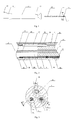
- Fig. 1 shows a structural schematic diagram of a perfused electrode catheter 10 with a temperature sensor of the present invention, which includes a catheter main body 12 having a distal end, at which an ablation portion 13 is provided, and a proximal end, at which a control handle 11 is provided.
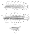
- Fig. 2 shows a sectional view of the catheter main body 12 according to one implementation of the present invention, illustrating the connection relationship between the catheter main body 12 and the ablation portion 13.
- the catheter main body 12 includes a reinforcement tube 22 and a main body tube 28 sleeved outside the reinforcement tube, wherein the main body tube 28 may be made of a biocompatible high polymer material, e.g. polyether block amide, polyurethane or nylon material, and the wall of the main body tube 28 preferably includes therein at least one metal wire braided layer (not shown in the figure), which may be a stainless steel wire braided layer. There may be one, two or more metal wire braided layers.
- the reinforcement tube 22 includes a central chamber 23 and may be made of any suitable high polymer material, such as being made by extrusion molding of polyether block amide, polyurethane, polyimide or nylon material.
- the catheter main body is preferably elongated and bendable, but typically incompressible in the length direction thereof.
- the central chamber 23 extends in the axial direction of the catheter main body 12; and a conducting wire 25, a traction wire 21 and a perfusion pipeline 26 extend inside the central chamber 23.
- the ablation portion 13 includes an elastic tip tube 31, which may be made of a biocompatible material and includes a distal end, a proximal end and at least one chamber, wherein the chamber may be a central or eccentric chamber.
- the elastic tip tube 31 includes a first eccentric chamber 35, a second eccentric chamber 36 and a third eccentric chamber 37.
- the wall of the elastic tip tube 31 includes therein at least one metal wire braided layer (not shown in the figure), which may be a stainless steel wire braided layer. There may be one, two or more metal wire braided layers.
- the proximal end of the elastic tip tube 31 is a thinned end 34 having an outer diameter matched with the inner diameter of the catheter main body 12, as shown in Fig.2 .
- the thinned end 34 is inserted into the catheter main body 12 and may be fixed by bonding, welding or other appropriate means.
- the thinned end 34 is bonded and fixed to the catheter main body 12 through UV cured adhesive.
- Fig. 3 shows a sectional view along line A-A of Fig. 1
- Fig. 4 shows a sectional view along line B-B of Fig. 3
- Fig. 5 shows a sectional view along line C-C of Fig. 3
- Fig. 6 shows a schematic diagram of a temperature sensor 33 shown in Fig. 4 and Fig. 5 .
- An ablation electrode 17 is disposed at the distal end of the elastic tip tube 31, and ring electrode(s) 16, the number of which may vary according to actual needs, are provided in the length direction of the elastic tip tube 31. There may be no ring electrode, or there may be one, two, three, four or more ring electrodes.
- the ablation electrode 17 includes an electrode shell 71 and a cavity 76 therein.
- the electrode shell 71 is further provided with a through hole 79 having a diameter of less than 1mm.
- the through hole 79 has a diameter of less than 0.5mm.
- the outer surface of the electrode shell 71 is a part which can be in contact with tissue to be ablated; and the cavity inside the electrode shell 71 is a part which cannot be in contact with the tissue.
- an insert 74 is provided in the cavity 76, wherein the insert 74 is provided at the proximal end of the electrode shell 71, and the distal end of the insert 74 extends into the cavity 76.
- the insert 74 may be cylindrical, disc-shaped or in other suitable shape and at least includes a through hole 81.
- the distal end of the through hole 81 extends into the through hole 79 of the electrode shell 71.
- the extending section of the through hole 81 and the insert 74 may be formed integrally or separately.
- a hollow tube is inserted into the through hole 81, or the distal end of the through hole 81 is connected with a pipeline or other suitable structure.
- the proximal end of the through hole 81 is opened at the proximal end of the insert 74, and the distal end of the through hole 81 is opened on the outer surface of the electrode shell 71 and is flush with the outer surface of the electrode shell 71.
- a temperature sensor 33 is provided at the distal end of the through hole 81 and is fixed by adhesive bonding. The temperature sensor 33 is located at the through hole in the electrode shell, where the thickness of the electrode shell is zero.
- the through hole 81 may be located close to the axis of the electrode shell 71 or close to the side wall of the electrode shell 71.
- the insert further includes a through hole 80, and the through hole 80 is a liquid passage for the inflow of perfusion liquid.
- an outer sleeve 332 is sleeved outside the temperature sensor 33 and the outer sleeve is made of an insulating material or an insulating and thermal insulation material.
- the distance between a temperature sensing portion 331 of the temperature sensor 33 and the top end of the temperature sensor is less than 0.5mm.
- the distance between the temperature sensing portion of the temperature sensor and the top end of the temperature sensor is less than 0.2mm. More preferably, the distance between the temperature sensing portion of the temperature sensor and the top end of the temperature sensor is less than 0.1mm.
- Insulating but heat-conducting glue 333 may be provided between the temperature sensing portion 331 and the top end, so as to improve the sensitivity of the temperature sensor and provide enough insulating property at the same time.
- the top end of the temperature sensor 33 may be flush with the outer surface of the electrode shell or located nearby the outer surface of the electrode shell. For example, a small part of the top end of the temperature sensor 33 protrudes out of the outer surface or retracts inside the outer surface.
- the insert 74 further includes a blind hole 82 in which a traction wire 21 is fixed.
- the through hole 80, the through hole 81 and the blind hole 82 are communicated with the first eccentric chamber 35, the second eccentric chamber 36 and the third eccentric chamber 37 of the elastic tip tube 31 respectively.
- a hollow tube which may be made of a suitable high polymer material or metallic material, e.g. polyimide or stainless steel, may be welded or bonded on each of the three holes 80, 81 and 82 of the insert 74 respectively.
- a heat-conducting insulation structure is provided between the temperature sensor 33 and the liquid passage, and the heat-conducting insulation structure is a nonmetallic heat insulation layer 78, which is disposed on the through hole 81.
- the nonmetallic heat insulation layer 78 is disposed on the inner wall and/or outer wall of the through hole 81.
- the inner wall and/or outer wall of the through hole 81 in the context may refer to the inner wall and/or outer wall of a section of the through hole 81 extending in the cavity, or the inner wall and/or outer wall of the entire through hole 81.
- the nonmetallic heat insulation layer 78 may be a tubular heat insulation layer inserted into the inner wall and/or onto the outer wall of the through hole 81, or may be a nonmetallic heat insulation layer coated on the inner wall and/or outer wall of the through hole 81.
- the through hole 81 itself may be used as a nonmetallic heat insulation layer.
- the nonmetallic heat insulation layer 78 is disposed on the inner wall and/or outer wall of the through hole 81.
- the through hole 81 of the insert When the extending section of the through hole 81 of the insert is made of a nonmetallic material, the through hole 81 itself may be used as a nonmetallic heat insulation layer.
- the nonmetallic heat insulation layer 78 may completely or partially cover the inner wall and/or outer wall of the through hole 81.
- the degree of heat insulation may be adjusted, so as to adjust the temperature detected by the temperature sensor 33.
- the material or thickness of the nonmetallic heat insulation layer is changed, the degree of heat insulation may also be adjusted.
- the nonmetallic heat insulation layer 78 is made of a nonmetallic material with a heat insulation function, which may be a high polymer material or ceramic or other suitable nonmetallic material.
- the nonmetallic heat insulation layer 78 may be made of a nonmetallic material with high temperature resistance. Because the nonmetallic heat insulation layer 78 is provided on the through hole 81, the temperature sensor is separated from the cooling effect of the perfusion liquid. The cooling effect of the perfusion liquid on the part where the temperature sensor is located is weakened, and the temperature sensor will be able to detect more temperature rise produced by the heating effect of radio-frequency currents.
- the insert 74 may be completely placed in the cavity of the electrode shell 71, or partially placed in the cavity of the electrode shell 71, as shown in Fig. 7 .
- the temperature sensor 33 may be a thermocouple, a thermistor or other device. There may be one, two, three or more temperature sensors. As shown in Fig. 4 , the distal end of the temperature sensor 33 extends into the second eccentric chamber 36 of the elastic tip tube 31 through the central chamber 23 of the catheter main body 12, then extends into the through hole 81, and is fixed at the distal end of the through hole 81 by glue bonding. The proximal end of the temperature sensor 33 extends into the control handle 11 through the central chamber 23, then extends out of the control handle 11 and is connected with a temperature monitoring device (not shown in the figure).
- the electrode shell 71 is provided with a plurality of small holes (not shown in the figure) serving as liquid passages for outflow of the perfumed liquid.
- the small holes may be formed in any suitable manner. They may be formed in a manner of machining, laser processing or electro-machining and the like, or may also be formed by using a porous material.
- a perfusion passage has a proximal end and a distal end, wherein the distal end of the perfusion passage extends into the first eccentric chamber 35 of the elastic tip tube 31 through the control handle 11 and the central chamber 23 of the catheter main body 12 and is communicated with the liquid passage of the ablation electrode 17.
- the perfusion pipeline 26 is provided in the perfusion passage. The distal end of the perfusion pipeline 26 may extend to the distal end of the first eccentric chamber 35 of the elastic tip tube 31 through the control handle 11 and the central chamber 23 of the catheter main body 12 and is communicated with the liquid passage of the ablation electrode 17, or may extend to the distal end of the central chamber 23 of the catheter main body 12 through the control handle 11 and is communicated with the first eccentric chamber 35 of the elastic tip tube 31.
- the perfusion pipeline 26 may be made of any suitable material, and the distal end of the perfusion pipeline 26 extends into the first eccentric chamber 35 of the elastic tip tube 31 through the central chamber 23 of the catheter main body 12 and is communicated with the through hole 80 in the insert 74.
- the proximal end of the perfusion pipeline 26 extends into the control handle 11 through the central chamber 23 of the catheter main body 12, and may be fixed in any suitable method known by those skilled in the art.
- the proximal end of the perfusion pipeline 26 is connected with a section of branch pipe 14, as shown in Fig. 1 , wherein the branch pipe 14 extends to the outside of the control handle 11, and the end of the branch pipe 14 is connected and fixed with a Luer taper 15.
- the perfusion liquid which may be any suitable liquid, such as normal saline, enters the perfusion pipeline 26 through the branch pipe 14, enters the cavity 76 of the ablation electrode 17 through the perfusion pipeline 26 and the through hole 80, and flows out of the catheter 10 through the holes in the electrode shell.
- the traction wire 21 is preferably made of stainless steel or nickel-titanium alloy. As shown in Fig. 2, Fig. 3 and Fig. 5 , the distal end of the traction wire 21 extends into the third eccentric chamber 37 of the elastic tip tube 31 through the central chamber 23, and a spring tube 29 is preferably sleeved outside a section of the traction wire 21 extending in the catheter main body 12
- the spring tube 29 is preferably of a tight structure with a tightening force, and a second protective sleeve (not shown in the figure) is sleeved outside the spring tube 29.
- the second protective sleeve may be made of any suitable material, preferably a polyamide material, and is used for the extension of the spring tube 29 therein.
- a first protective sleeve 32 is preferably sleeved outside a section of traction wire 21 extending in the elastic tip tube 31.
- the first protective sleeve 32 may be made of any suitable material, preferably a polytetrafluoroethylene material, and is provided in the elastic tip tube 31 and used for the extension of the traction wire 21 therein.
- the distal end of the traction wire 21 extends into the hole 82 in the insert 74, and the end thereof is fixed by welding, bonding or other suitable manner, preferably being fixed by welding.
- the proximal end of the traction wire 21 is fixed on the control handle 11 by adopting any suitable method known by those skilled in the art.
- a method for fixing a traction wire as disclosed in United States Patent US6120476 may be used.
- the distal end of the conducting wire 25 extends into the second eccentric chamber 36 of the elastic tip tube 31 through the central chamber 23, and is connected with the ablation electrode 17, the ring electrode 16 and the temperature sensor 33 respectively in a manner of welding or other suitable manner, preferably being fixed by welding.
- a conduit 27 is provided outside the conducting wire 25.
- the proximal end of the conducting wire 25 is fixed on the control handle 11 by adopting any suitable method known by those skilled in the art, such as being fixed on a corresponding plug by welding.
- the nonmetallic heat insulation layer 78 is provided on the through hole 81 of the insert 74, and the temperature sensor 33 may be provided on the inner surface of the electrode shell 71 or in the through hole of the electrode shell 71 or partially provided in the electrode shell, so the temperature detected by the ablation electrode of the present invention is closer to the temperature of the tissue under the same catheter radio-frequency ablation power and perfusion condition commonly used in clinical practice.
- the temperature sensor 33 is provided on the inner surface of the electrode shell 71, more preferably, the temperature sensor 33 is partially provided in the electrode shell 71, and even more preferably, the temperature sensor 33 is provided in the through hole of the electrode shell 71.
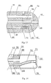
- Fig. 8 is a sectional view of the ablation electrode 17 according to a further implementation of the present invention.
- the ablation electrode 17 includes an electrode shell 71 and a cavity 76 therein, and the insert 74 is provided at the proximal end of the electrode shell 71.
- the insert 74 may be cylindrical, disc-shaped or in other suitable shape and at least includes a through hole 81, and the distal end of the through hole 81 extends into a through hole 79 of the electrode shell 71.
- the extending section of the through hole 81 and the insert 74 may be formed integrally or separately.
- a hollow tube is inserted into the through hole 81, or the distal end of the through hole 81 is connected with a pipeline or other suitable structure.
- the proximal end of the through hole 81 is opened at the proximal end of the insert 74.
- the distal end of the through hole 81 turns in the cavity 76, extends into the through hole 79 in the side wall of the electrode shell 71, is opened on the side wall, and is flush with the outer surface of the electrode shell 71, as shown in Fig. 8 .
- a temperature sensor 33 is provided at the distal end of the through hole 81 and is fixed by glue bonding.
- the insert 74 further includes a through hole 80, and the through hole 80 is a liquid passage for inflow of perfusion liquid.
- the through hole 80 and the through hole 81 are communicated with the first eccentric chamber 35 and the second eccentric chamber 36 of the elastic tip tube 31 respectively.
- a nonmetallic heat insulation layer 78 is provided on the through hole 81.
- the nonmetallic heat insulation layer 78 is provided on the inner wall and/or outer wall of the through hole 81.
- the through hole 81 itself may be used as a nonmetallic heat insulation layer.
- the nonmetallic heat insulation layer 78 is provided on the inner wall and/or outer wall of the through hole 81.
- the through hole 81 itself may be used as a nonmetallic heat insulation layer.
- the rest structures of the catheter 10 are the same as those in the embodiments shown in Fig. 4 and Fig. 5 .
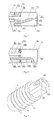
- Fig. 9 shows a structural diagram of the ablation electrode 17 according to a further implementation of the present invention.
- the ablation electrode 17 includes a cylindrical side wall surface 77 and a rounded top surface 75, and may be formed separately or integrally. Holes 72 for outflow of the perfusion liquid from the ablation electrode 17 are formed in the rounded top surface 75.
- Annular grooves 73 are provided in the cylindrical side wall surface 77, and the annular grooves 73 may be provided in a conventional manner for those skilled in the art. For example, the annular grooves 73 may be provided in a manner mentioned in United States Patent US20080294158 .
- Fig. 10 shows a sectional view of the ablation electrode 17 shown in Fig. 8 .
- the ablation electrode 17 includes a cavity 76, and an insert 74 is provided at the proximal end of the electrode shell 71.
- the insert 74 is provided at the proximal end of the ablation electrode 17.
- the insert 74 may be cylindrical, disc-shaped or in other suitable shape and includes a through hole 81, and the distal end of the through hole 81 extends into the through hole 79 of the electrode shell 71.
- the extending section of the through hole 81 and the insert 74 may be formed integrally or separately. For example, a hollow tube is inserted into the through hole 81, or the distal end of the through hole 81 is connected with a pipeline or other suitable structures.
- the proximal end of the through hole 81 is opened at the proximal end of the insert 74, and the distal end of the through hole 81 is opened on the outer surface of the electrode shell 71 and is flush with the outer surface of the electrode shell 71.
- a temperature sensor 33 is provided at the distal end of the through hole 81 and is fixed by glue bonding.
- the insert 74 further includes a through hole 80, and the through hole 80 is a liquid passage for inflow of perfusion liquid, which may be a central chamber or an eccentric chamber.
- the nonmetallic heat insulation layer 78 is provided on the through hole 81.
- the nonmetallic heat insulation layer 78 is provided on the inner wall and/or outer wall of the through hole 81.
- the through hole 81 itself may be used as a nonmetallic heat insulation layer.
- the nonmetallic heat insulation layer 78 is provided on the inner wall and/or outer wall of the through hole 81.
- the through hole 81 of the insert When the extending section of the through hole 81 of the insert is made of a nonmetallic material, the through hole 81 itself may be used as a nonmetallic heat insulation layer.
- the nonmetallic heat insulation layer 78 may completely or partially cover the inner wall and/or outer wall of the through hole 81.
- an extension tube 83 may also be provided at the distal end of the hollow tube in the through hole 80, and may be fixed by glue bonding, welding or other suitable manner.
- the extension tube 83 and the hollow tube may also be formed integrally.
- the insert 74 may be completely placed in the cavity of the electrode shell 71, or partially placed in the cavity of the electrode shell 71, as shown in Fig. 10 .
- the rest structures of the catheter 10 may be the same as those in the embodiments shown in Fig. 4 and Fig. 5 , or the catheter structures in United States Patent US20080294158 .
- Fig. 11 shows a sectional view of the ablation electrode 17 according to a further implementation of the present invention
- Fig. 12 shows a sectional view of the ablation electrode 17 in Fig. 11
- the ablation electrode 17 includes an electrode shell 71 and a cavity 76 therein, and the insert 74 is provided at the proximal end of the electrode shell 71.
- the insert 74 may be circular or in other suitable shape, such as cylindrical, disc-shaped and the like.
- the insert includes a through hole 81, and the distal end of the through hole 81 extends into the through hole 79 of the electrode shell 71.
- the extending section of the through hole 81 and the insert 74 may be formed integrally or separately.
- a hollow tube is inserted into the through hole 81, or the distal end of the through hole 81 is connected with a pipeline or other suitable structures.
- the proximal end of the through hole 81 is opened at the proximal end of the insert 74.
- the distal end of the through hole 81 is opened on the outer surface of the electrode shell 71 and is flush with the outer surface of the electrode shell 71.
- a temperature sensor 33 is provided at the distal end of the through hole 81 and is fixed by glue bonding.
- a stainless steel tube is welded on the inner wall of the through hole 81, and the distal end of the traction wire 21 extends into the stainless steel tube and is fixed by welding.
- the perfusion passage is provided with a proximal end and a distal end, wherein the distal end of the perfusion passage extends into the first eccentric chamber 35 of the elastic tip tube 31 through the control handle 11 and the central chamber 23 of the catheter main body 12, and is communicated with the liquid passage of the ablation electrode 17.
- a perfusion pipeline 26 is provided in the perfusion passage, and the distal end of the perfusion pipeline 26 extends to the distal end of the central chamber 23 of the catheter main body 12 through the control handle 11 and is communicated with the first eccentric chamber 35 of the elastic tip tube 31.
- the elastic tip tube 31 may also have a structure with four or more chambers, so that the perfusion liquid may flow into the cavity 76 of the electrode shell through at least two eccentric chambers of the elastic tip tube 31.
- the distal end of the conducting wire 25 is welded on the stainless steel tube, and a sealant is filled at the distal end of the conducting wire and the proximal end of the through hole 81 to avoid direct contact with the perfusion liquid.
- the nonmetallic heat insulation layer 78 is provided on the through hole 81.
- the nonmetallic heat insulation layer 78 is provided on the inner wall and/or outer wall of the through hole 81.
- the through hole 81 itself may be used as a nonmetallic heat insulation layer.
- the nonmetallic heat insulation layer 78 is provided on the inner wall and/or outer wall of the through hole 81.
- the through hole 81 itself may be used as a nonmetallic heat insulation layer.
- the rest structure of the catheter 10 is the same as that in the embodiments shown in Fig. 4 and Fig. 5 , the embodiment shown in Fig. 8 or the embodiments shown in Fig. 9 and Fig. 10 .
- Fig. 13 shows a sectional view of the ablation electrode 17 according to a further implementation of the present invention.
- the ablation electrode 17 includes at least one liquid passage 80, the liquid passage 80 is provided with an opening at the proximal end of the ablation electrode 17, and the perfusion liquid may flow to the outer surface of the ablation electrode 17 through the liquid passage 80.
- the perfusion liquid may flow through the ablation electrode.
- the liquid passage is provided with a plurality of branches which extend to and are opened on the outer surface of the ablation electrode.
- the ablation electrode 17 further includes a through hole 81, and the distal end of the through hole 81 is opened on the outer surface of the electrode shell 71 and is flush with the outer surface of the electrode shell 71.
- the temperature sensor 33 is provided at the distal end of the through hole 81 and is fixed by glue bonding.
- the ablation electrode 17 further includes a blind hole 82 in which the traction wire 21 is fixed.
- the through hole 80, the through hole 81 and the blind hole 82 are communicated with the first eccentric chamber 35, the second eccentric chamber 36 and the third eccentric chamber 37 of the elastic tip tube 31 respectively.
- the nonmetallic heat insulation layer 78 is completely or partially provided on the inner wall of the through hole 81.
- the nonmetallic heat insulation layer 78 may be a tubular heat insulation layer inserted into the through hole 81, or may be a nonmetallic heat insulation layer coated on the inner wall of the through hole 81.
- the nonmetallic heat insulation layer 78 is made of a material with a heat insulation function, and may be made of a nonmetallic material such as a high polymer material, ceramic or other suitable nonmetallic material.
- the nonmetallic heat insulation layer 78 may be made of a nonmetallic material with high temperature resistance.
- the liquid passage 80 may also be completely or partially provided with the nonmetallic heat insulation layer 78 therein.
- the rest structures of the catheter 10 are the same as those in the implementations shown in Fig. 4 and Fig. 5 or the catheter structures in Chinese Patent CN201020215408.8 .
- Fig. 14 is a sectional view of the ablation electrode 17 according to a further implementation of the present invention.
- the ablation electrode 17 includes an electrode shell 71 and a cavity 76 therein, and an insert 74 is provided at the proximal end of the electrode shell 71.
- the insert 74 may be cylindrical, disc-shaped or in other suitable shape and at least includes a through hole 81, and the distal end of the through hole 81 extends into a through hole 79 of the electrode shell 71.
- the extending section of the through hole 81 and the insert 74 may be formed integrally or separately. For example, a hollow tube is inserted into the through hole 81, or the distal end of the through hole 81 is connected with a pipeline or other suitable structure.
- the proximal end of the through hole 81 is opened at the proximal end of the insert 74.
- the distal end of the through hole 81 extends to the inner surface of the electrode shell 71 and is flush with the inner surface of the electrode shell 71, or may partially extend into the electrode shell 71.
- a temperature sensor 33 is provided at the distal end of the through hole 81 and is fixed by glue bonding.
- a hollow tube may be provided in the through hole 81.
- the distal end of the hollow tube extends to the inner surface of the electrode shell 71 and is flush with the inner surface of the electrode shell 71, or may partially extend into the electrode shell 71.
- the distal end of the hollow tube has a closed construction.
- the temperature sensor 33 is glue bonded and fixed at the distal end of the hollow tube.
- the thickness of the electrode shell where the temperature sensor is located is less than 0.2mm.
- the thickness of the electrode shell where the temperature sensor is located is less than 0.1mm.
- the insert 74 further includes a through hole 80, and the through hole 80 is a liquid passage for inflow of perfusion liquid.
- the through hole 80 and the through hole 81 are communicated with the first eccentric chamber 35 and the second eccentric chamber 36 of the elastic tip tube 31 respectively.
- a nonmetallic heat insulation layer 78 is provided on the through hole 81.
- the nonmetallic heat insulation layer 78 is provided on the inner wall and/or outer wall of the through hole 81.
- the through hole 81 itself may be used as a nonmetallic heat insulation layer.
- the nonmetallic heat insulation layer 78 is provided on the inner wall and/or outer wall of the through hole 81.
- the through hole 81 itself may be used as a nonmetallic heat insulation layer.
- the temperature sensor 33 and a part of the electrode shell which is not directly cooled by the perfusion liquid may be in direct contact, or may be connected through a metallic material, such as welding, or connected through a nonmetallic heat-conducting material, such as bonding through a heat-conducting glue, or connected through both a metallic material and a nonmetallic heat-conducting material, or connected through other suitable connecting methods. Therefore, the heat conductivity between the temperature sensor 33 and the outer wall of the electrode shell 71 is better than that between the temperature sensor 33 and the liquid passage.
- the part of the electrode shell which is not directly cooled by the perfusion liquid in the present invention refers to such a part on the electrode shell that is not in direct contact with the perfusion liquid.
- the liquid passage in the present invention includes a part through which the perfusion liquid flows in the ablation electrode 17, including the hole 80, the cavity 76 of the electrode shell 17 and the part on the electrode shell for outflow of the perfusion liquid.
- the rest structures of the catheter 10 are the same as those in the embodiment shown in Fig. 4 and Fig. 5 , the embodiment shown in Fig. 9 and Fig. 10 , the embodiment shown in Fig. 11 and Fig. 12 or other embodiments.
- the implementations of the present invention are not limited to the above-mentioned embodiments, and in order to meet other requirements of the liquid passages or requirements of mechanical structures, the form of the electrode body and/or the insert may be changed (e.g. the diameter is changed, the number of passages is adjusted, and the length is changed), so as to meet the requirements upon cooling and temperature measuring during ablation and the requirements upon the connection between the ablation electrode and the catheter main body.
- the form of the electrode body and/or the insert may be changed (e.g. the diameter is changed, the number of passages is adjusted, and the length is changed), so as to meet the requirements upon cooling and temperature measuring during ablation and the requirements upon the connection between the ablation electrode and the catheter main body.
Landscapes
- Health & Medical Sciences (AREA)
- Life Sciences & Earth Sciences (AREA)
- Surgery (AREA)
- Engineering & Computer Science (AREA)
- Plasma & Fusion (AREA)
- Medical Informatics (AREA)
- Otolaryngology (AREA)
- Physics & Mathematics (AREA)
- Cardiology (AREA)
- Biomedical Technology (AREA)
- Heart & Thoracic Surgery (AREA)
- Nuclear Medicine, Radiotherapy & Molecular Imaging (AREA)
- Molecular Biology (AREA)
- Animal Behavior & Ethology (AREA)
- General Health & Medical Sciences (AREA)
- Public Health (AREA)
- Veterinary Medicine (AREA)
- Surgical Instruments (AREA)
- Media Introduction/Drainage Providing Device (AREA)
Abstract
Description
- The present application claims the priority of Chinese patent application
201210079501.4 filed on March 23, 2012 - The present invention relates to an ablation electrode and a perfused electrode catheter using the electrode, and more particularly relates to an ablation electrode with a temperature sensor and a perfused electrode catheter using the same.
- Electrode catheters have been widely applied to clinical practice for many years. They may be used in hearts to map and stimulate electrical activities and perform ablation therapy on positions occurring abnormal electrical activities.
- In clinical use, an electrode catheter enters the body through a main vein or artery, e.g. through a femoral vein, and then is guided into the concerned heart chamber. In some applications, the catheter is expected to have the capability of injecting and/or extracting liquid, and such a function may be completed by a perfused catheter.
- In a specific application example, an ablation injury is generated in the heart through catheter intracardiac ablation, so as to cut off an abnormal electrocardio conduction path in the heart. A typical ablation operation process includes that, a catheter provided with an ablation electrode at the distal end thereof is inserted into the heart chamber, a reference electrode is provided and generally attached and fixed to the skin surface of a patient, and a radio frequency (RF) voltage is applied between the ablation electrode and the reference electrode to generate RF electric current flowing through media therebetween, including blood and tissue. The distribution of the electric current depends on the ratio of the contact area of the ablation electrode and the tissue to the contact area of the ablation electrode and the blood. After the heart tissue is sufficiently heated by the heating effect of the RF electric current, tissue cells are destroyed to form an injury in the heart tissue, and the injured tissue does not form electrical conduction. In this process, the heated tissue simultaneously heats the ablation electrode through heat conduction. If the temperature of the electrode is high enough, e.g. higher than 60 °C, a thin film formed by dehydration of blood protein may be formed on the surface of the electrode, and if the temperature is further raised, the dehydrated protein layer is gradually thickened, and thus blood coagulation occurs on the surface of the electrode. Because the electrical conductivity of the dehydrated biomaterial is lower than that of the intracardiac tissue, the impedance for the RF electric current flowing into the tissue is increased, and when the impedance becomes high up to a certain degree, the catheter must be taken out of the body to clean the ablation electrode.
- Another method for achieving the aforementioned desired effect is to perfuse the ablation electrode. For example, the ablation electrode is actively cooled by adopting normal saline at room temperature, rather than depending on the relatively passive cooling effect of the blood. Under such a condition, the electrode is effectively cooled, and the surface temperature thereof is no longer the main factor of producing impedance increase and even blood coagulation, so that the intensity of the RF electric current is no longer limited by the surface temperature, the electric current may be increased, and thus a larger injury closer to a sphere shape is formed, generally in a size of 10mm to 12mm.
- United States Patents
US5, 643,197 andUS5, 462,521 disclose a perfused electrode made of a porous material, wherein the electrode has a metallic structure formed by sintering tiny particles, and the liquid cooling of the electrode structure is more effective through multiple interconnected channels. Moreover, the porous structure enables liquid flow to form a liquid film uniformly distributed on the surface of the electrode and becoming a blocking layer between the blood and the surface of the electrode. - Therefore, a novel perfused catheter is needed.
- The present invention provides an ablation electrode for a catheter, including an electrode shell, and an optional cavity and a temperature sensor in the electrode shell; a liquid passage for outflow of perfusion liquid is provided in the electrode shell, and a liquid passage for inflow of the perfusion liquid is provided in the proximal end of the electrode shell; and a heat-conducting insulation structure is provided between the temperature sensor and the liquid passages, and the thickness of the electrode shell where the temperature sensor is located is less than 0.2mm.
- The term "optional" used in the context expresses the meaning of "not indispensable" or "not essential". For example, "optional cavity" indicates that there may be or may not be the cavity. This may be selected by those skilled in the art according to conditions.
- In an implementation of the present invention, the electrode shell is provided with a through hole, and the temperature sensor is provided in the through hole.
- In a specific implementation of the present invention, an insert is provided at the proximal end of the electrode shell, the distal end of the insert extends into the cavity, and the insert includes at least one through hole; the distal end of the through hole in the insert extends into the through hole of the electrode shell, the proximal end of the through hole in the insert is opened at the proximal end of the insert, the distal end of the through hole in the insert is opened on the outer surface of the electrode shell and is flush with the outer surface of the electrode shell, and the temperature sensor is provided at the distal end of the through hole in the insert.
- The diameter of the through hole in the electrode shell may be less than 1mm; and preferably, the diameter of the through hole in the electrode shell is less than 0.5mm.
- In a specific implementation of the present invention, an insert is provided at the proximal end of the electrode shell, the distal end of the insert extends into the cavity, and the insert includes at least one through hole; the distal end of the through hole in the insert extends to the inner surface of the electrode shell and is flush with the inner surface of the electrode shell, or the distal end of the through hole in the insert partially extends into the electrode shell; the proximal end of the through hole in the insert is opened at the proximal end of the insert, the distal end of the through hole in the insert is opened or has a closed construction, and the temperature sensor is provided at the distal end of the through hole in the insert; and preferably, the thickness of the electrode shell where the temperature sensor is located is less than 0.1 mm.
- Preferably, the heat-conducting insulation structure is a nonmetallic heat insulation layer.
- The nonmetallic heat insulation layer may be provided on the inner wall and/or outer wall of the through hole in the insert; preferably, the inner wall and/or outer wall of the through hole in the insert is partially or completely provided with the nonmetallic heat insulation layer.
- The distance between a temperature sensing portion of the temperature sensor and the top end of the temperature sensor may be less than 0.5mm; preferably, the distance between the temperature sensing portion of the temperature sensor and the top end of the temperature sensor is less than 0.2mm; and more preferably, the distance between the temperature sensing portion of the temperature sensor and the top end of the temperature sensor is less than 0.1 mm.
- The nonmetallic heat insulation layer may be made of a high polymer material or ceramic.
- The present invention provides a perfused electrode catheter, which is characterized by including:
- a catheter main body having a proximal end, a distal end and a central chamber penetrating through the catheter main body;
- an ablation portion, comprising a section of elastic tip tube, and having a proximal end, a distal end and at least one chamber penetrating through ablation portion, the proximal end of the ablation portion is fixedly connected with the distal end of the catheter main body;
- an ablation electrode, fixedly connected to the distal end of the ablation portion, and including an electrode shell, and an optional cavity and a temperature sensor in the electrode shell, wherein a liquid passage for outflow of perfusion liquid is provided in the electrode shell, and a liquid passage for inflow of the perfusion liquid is provided in the proximal end of the electrode shell; and a heat-conducting insulation structure is provided between the temperature sensor and the liquid passages, and the thickness of the electrode shell where the temperature sensor is located is less than 0.2mm;
- a perfusion passage, having a proximal end and a distal end, , the distal end of the perfusion passage extends into the chamber of the ablation portion through the central chamber of the catheter main body and is communicated with the liquid passage of the ablation electrode.
- In an implementation of the present invention, the electrode shell is provided with a through hole, and the temperature sensor is provided in the through hole.
- In a specific implementation of the present invention, an insert is provided at the proximal end of the electrode shell, the distal end of the insert extends into the cavity, and the insert includes at least one through hole; the distal end of the through hole in the insert extends into the through hole of the electrode shell, the proximal end of the through hole in the insert is opened at the proximal end of the insert, the distal end of the through hole in the insert is opened on the outer surface of the electrode shell and is flush with the outer surface of the electrode shell, and the temperature sensor is provided at the distal end of the through hole in the insert.
- The diameter of the through hole in the electrode shell may be less than 1mm; and preferably, the diameter of the through hole in the electrode shell is less than 0.5mm.
- In a specific implementation of the present invention, an insert is provided at the proximal end of the electrode shell, the distal end of the insert extends into the cavity, and the insert includes at least one through hole; the distal end of the through hole in the insert extends to the inner surface of the electrode shell and is flush with the inner surface of the electrode shell, or he distal end of the through hole in the insert partially extends into the electrode shell; the proximal end of the through hole in the insert is opened at the proximal end of the insert, the distal end of the through hole in the insert is opened or has a closed construction, and the temperature sensor is provided at the distal end of the through hole in the insert; and preferably, the thickness of the electrode shell where the temperature sensor is located is less than 0.1mm.
- A perfusion pipeline is provided in the perfusion passage, and the distal end of the perfusion pipeline may extend to the distal end of the chamber of the ablation portion through a control handle and the central chamber of the catheter main body and is communicated with the liquid passage of the ablation electrode, or extend to the distal end of the central chamber of the catheter main body through the control handle and is communicated with at least one chamber penetrating through the ablation portion. Preferably, the heat-conducting insulation structure is a nonmetallic heat insulation layer.
- The nonmetallic heat insulation layer may be provided on the inner wall and/or outer wall of the through hole in the insert; preferably, the inner wall and/or outer wall of the through hole in the insert is partially or completely provided with the nonmetallic heat insulation layer.
- The distance between a temperature sensing portion of the temperature sensor and the top end of the temperature sensor may be less than 0.5mm; preferably, the distance between the temperature sensing portion of the temperature sensor and the top end of the temperature sensor is less than 0.2mm; and more preferably, the distance between the temperature sensing portion of the temperature sensor and the top end of the temperature sensor is less than 0.1 mm.
- The nonmetallic heat insulation layer may be made of a high polymer material or ceramic.
- In a preferred implementation of the present invention, the perfused electrode catheter includes the heat-conducting insulation structure, so that the temperature sensor is separated from the cooling effect of the perfusion liquid, the cooling effect of the perfusion liquid on the part where the temperature sensor is located is weakened, and the heating effect of circumferential heat conduction from the outer wall of the electrode shell on the part where the temperature sensor is located is maintained; and the temperature sensor is provided on the inner surface of the electrode shell or in the through hole of the electrode shell or partially extends into the electrode shell, so that the temperature sensor may detect more temperature rise produced by the heating effect of radio-frequency electric currents.
-
-
Fig. 1 is a structural schematic diagram of a perfused electrode catheter according to the present invention; -
Fig. 2 shows a sectional view of a cathetermain body 12 according to a preferable implementation of the present invention, illustrating the connection relationship between the cathetermain body 12 and anablation portion 13; -
Fig. 3 shows a sectional view along line A-A ofFig. 1 ; -
Fig. 4 shows a sectional view along line B-B ofFig. 3 ; -
Fig. 5 shows a sectional view along line C-C ofFig. 3 ; -
Fig. 6 shows a schematic diagram of atemperature sensor 33 in anablation electrode 17 according to a preferable implementation of the present invention; -
Fig. 7 shows a sectional view of anablation electrode 17 according to a further preferable implementation of the present invention; -
Fig. 8 shows a structural diagram of anablation electrode 17 according to a further preferable implementation of the present invention; -
Fig. 9 shows a sectional view of theablation electrode 17 shown inFig. 8 ; -
Fig. 10 shows a sectional view of anablation electrode 17 according to a further preferable implementation of the present invention; -
Fig. 11 shows a sectional view of theablation electrode 17 shown inFig. 10 ; -
Fig. 12 shows a sectional view of anablation electrode 17 according to a further preferable implementation of the present invention; -
Fig. 13 shows a sectional view of anablation electrode 17 according to a further preferable implementation of the present invention; and -
Fig. 14 shows a sectional view of anablation electrode 17 according to a further preferable implementation of the present invention. - The technical solution of the present invention will be further described below in detail with reference to the implementations and in combination with the accompanying drawings, but the present invention is not merely limited to the following implementations.
-
Fig. 1 shows a structural schematic diagram of a perfusedelectrode catheter 10 with a temperature sensor of the present invention, which includes a cathetermain body 12 having a distal end, at which anablation portion 13 is provided, and a proximal end, at which acontrol handle 11 is provided. -
Fig. 2 shows a sectional view of the cathetermain body 12 according to one implementation of the present invention, illustrating the connection relationship between the cathetermain body 12 and theablation portion 13. The cathetermain body 12 includes areinforcement tube 22 and amain body tube 28 sleeved outside the reinforcement tube, wherein themain body tube 28 may be made of a biocompatible high polymer material, e.g. polyether block amide, polyurethane or nylon material, and the wall of themain body tube 28 preferably includes therein at least one metal wire braided layer (not shown in the figure), which may be a stainless steel wire braided layer. There may be one, two or more metal wire braided layers. Thereinforcement tube 22 includes acentral chamber 23 and may be made of any suitable high polymer material, such as being made by extrusion molding of polyether block amide, polyurethane, polyimide or nylon material. The catheter main body is preferably elongated and bendable, but typically incompressible in the length direction thereof. Thecentral chamber 23 extends in the axial direction of the cathetermain body 12; and aconducting wire 25, atraction wire 21 and aperfusion pipeline 26 extend inside thecentral chamber 23. - The
ablation portion 13 includes anelastic tip tube 31, which may be made of a biocompatible material and includes a distal end, a proximal end and at least one chamber, wherein the chamber may be a central or eccentric chamber. In one specific implementation of the present invention, as shown inFig.2 , theelastic tip tube 31 includes a firsteccentric chamber 35, a secondeccentric chamber 36 and a thirdeccentric chamber 37. Preferably, the wall of theelastic tip tube 31 includes therein at least one metal wire braided layer (not shown in the figure), which may be a stainless steel wire braided layer. There may be one, two or more metal wire braided layers. Preferably, the proximal end of theelastic tip tube 31 is a thinnedend 34 having an outer diameter matched with the inner diameter of the cathetermain body 12, as shown inFig.2 . The thinnedend 34 is inserted into the cathetermain body 12 and may be fixed by bonding, welding or other appropriate means. For example, the thinnedend 34 is bonded and fixed to the cathetermain body 12 through UV cured adhesive. -
Fig. 3 shows a sectional view along line A-A ofFig. 1 ,Fig. 4 shows a sectional view along line B-B ofFig. 3 ,Fig. 5 shows a sectional view along line C-C ofFig. 3 , andFig. 6 shows a schematic diagram of atemperature sensor 33 shown inFig. 4 and Fig. 5 . Anablation electrode 17 is disposed at the distal end of theelastic tip tube 31, and ring electrode(s) 16, the number of which may vary according to actual needs, are provided in the length direction of theelastic tip tube 31. There may be no ring electrode, or there may be one, two, three, four or more ring electrodes. Theablation electrode 17 includes anelectrode shell 71 and acavity 76 therein. Theelectrode shell 71 is further provided with a throughhole 79 having a diameter of less than 1mm. Preferably, the throughhole 79 has a diameter of less than 0.5mm. The outer surface of theelectrode shell 71 is a part which can be in contact with tissue to be ablated; and the cavity inside theelectrode shell 71 is a part which cannot be in contact with the tissue. - In a preferable implementation, as shown in
Fig. 4 and Fig. 5 , aninsert 74 is provided in thecavity 76, wherein theinsert 74 is provided at the proximal end of theelectrode shell 71, and the distal end of theinsert 74 extends into thecavity 76. Theinsert 74 may be cylindrical, disc-shaped or in other suitable shape and at least includes a throughhole 81. The distal end of the throughhole 81 extends into the throughhole 79 of theelectrode shell 71. The extending section of the throughhole 81 and theinsert 74 may be formed integrally or separately. For example, a hollow tube is inserted into the throughhole 81, or the distal end of the throughhole 81 is connected with a pipeline or other suitable structure. The proximal end of the throughhole 81 is opened at the proximal end of theinsert 74, and the distal end of the throughhole 81 is opened on the outer surface of theelectrode shell 71 and is flush with the outer surface of theelectrode shell 71. Atemperature sensor 33 is provided at the distal end of the throughhole 81 and is fixed by adhesive bonding. Thetemperature sensor 33 is located at the through hole in the electrode shell, where the thickness of the electrode shell is zero. The throughhole 81 may be located close to the axis of theelectrode shell 71 or close to the side wall of theelectrode shell 71. The insert further includes a throughhole 80, and the throughhole 80 is a liquid passage for the inflow of perfusion liquid. - As shown in
Fig. 6 , anouter sleeve 332 is sleeved outside thetemperature sensor 33 and the outer sleeve is made of an insulating material or an insulating and thermal insulation material. The distance between atemperature sensing portion 331 of thetemperature sensor 33 and the top end of the temperature sensor is less than 0.5mm. Preferably, the distance between the temperature sensing portion of the temperature sensor and the top end of the temperature sensor is less than 0.2mm. More preferably, the distance between the temperature sensing portion of the temperature sensor and the top end of the temperature sensor is less than 0.1mm. Insulating but heat-conductingglue 333 may be provided between thetemperature sensing portion 331 and the top end, so as to improve the sensitivity of the temperature sensor and provide enough insulating property at the same time. The top end of thetemperature sensor 33 may be flush with the outer surface of the electrode shell or located nearby the outer surface of the electrode shell. For example, a small part of the top end of thetemperature sensor 33 protrudes out of the outer surface or retracts inside the outer surface. - The
insert 74 further includes ablind hole 82 in which atraction wire 21 is fixed. The throughhole 80, the throughhole 81 and theblind hole 82 are communicated with the firsteccentric chamber 35, the secondeccentric chamber 36 and the thirdeccentric chamber 37 of theelastic tip tube 31 respectively. Preferably, a hollow tube, which may be made of a suitable high polymer material or metallic material, e.g. polyimide or stainless steel, may be welded or bonded on each of the threeholes insert 74 respectively. - A heat-conducting insulation structure is provided between the
temperature sensor 33 and the liquid passage, and the heat-conducting insulation structure is a nonmetallicheat insulation layer 78, which is disposed on the throughhole 81. When the extending section of the throughhole 81 and theinsert 74 are formed integrally and theinsert 74 is made of a metallic material, the nonmetallicheat insulation layer 78 is disposed on the inner wall and/or outer wall of the throughhole 81. The inner wall and/or outer wall of the throughhole 81 in the context may refer to the inner wall and/or outer wall of a section of the throughhole 81 extending in the cavity, or the inner wall and/or outer wall of the entire throughhole 81. The nonmetallicheat insulation layer 78 may be a tubular heat insulation layer inserted into the inner wall and/or onto the outer wall of the throughhole 81, or may be a nonmetallic heat insulation layer coated on the inner wall and/or outer wall of the throughhole 81. When theinsert 74 is made of a nonmetallic material, the throughhole 81 itself may be used as a nonmetallic heat insulation layer. When the extending section of the throughhole 81 and theinsert 74 are formed separately and the extending section of the throughhole 81 is made of the metallic material, the nonmetallicheat insulation layer 78 is disposed on the inner wall and/or outer wall of the throughhole 81. When the extending section of the throughhole 81 of the insert is made of a nonmetallic material, the throughhole 81 itself may be used as a nonmetallic heat insulation layer. The nonmetallicheat insulation layer 78 may completely or partially cover the inner wall and/or outer wall of the throughhole 81. When the nonmetallicheat insulation layer 78 partially covers the inner wall and/or outer wall of the throughhole 81, the degree of heat insulation may be adjusted, so as to adjust the temperature detected by thetemperature sensor 33. When the material or thickness of the nonmetallic heat insulation layer is changed, the degree of heat insulation may also be adjusted. The nonmetallicheat insulation layer 78 is made of a nonmetallic material with a heat insulation function, which may be a high polymer material or ceramic or other suitable nonmetallic material. The nonmetallicheat insulation layer 78 may be made of a nonmetallic material with high temperature resistance. Because the nonmetallicheat insulation layer 78 is provided on the throughhole 81, the temperature sensor is separated from the cooling effect of the perfusion liquid. The cooling effect of the perfusion liquid on the part where the temperature sensor is located is weakened, and the temperature sensor will be able to detect more temperature rise produced by the heating effect of radio-frequency currents. - The
insert 74 may be completely placed in the cavity of theelectrode shell 71, or partially placed in the cavity of theelectrode shell 71, as shown inFig. 7 . - The
temperature sensor 33 may be a thermocouple, a thermistor or other device. There may be one, two, three or more temperature sensors. As shown inFig. 4 , the distal end of thetemperature sensor 33 extends into the secondeccentric chamber 36 of theelastic tip tube 31 through thecentral chamber 23 of the cathetermain body 12, then extends into the throughhole 81, and is fixed at the distal end of the throughhole 81 by glue bonding. The proximal end of thetemperature sensor 33 extends into the control handle 11 through thecentral chamber 23, then extends out of the control handle 11 and is connected with a temperature monitoring device (not shown in the figure). - The
electrode shell 71 is provided with a plurality of small holes (not shown in the figure) serving as liquid passages for outflow of the perfumed liquid. The small holes may be formed in any suitable manner. They may be formed in a manner of machining, laser processing or electro-machining and the like, or may also be formed by using a porous material. - A perfusion passage has a proximal end and a distal end, wherein the distal end of the perfusion passage extends into the first
eccentric chamber 35 of theelastic tip tube 31 through the control handle 11 and thecentral chamber 23 of the cathetermain body 12 and is communicated with the liquid passage of theablation electrode 17. Theperfusion pipeline 26 is provided in the perfusion passage. The distal end of theperfusion pipeline 26 may extend to the distal end of the firsteccentric chamber 35 of theelastic tip tube 31 through the control handle 11 and thecentral chamber 23 of the cathetermain body 12 and is communicated with the liquid passage of theablation electrode 17, or may extend to the distal end of thecentral chamber 23 of the cathetermain body 12 through the control handle 11 and is communicated with the firsteccentric chamber 35 of theelastic tip tube 31. - The
perfusion pipeline 26 may be made of any suitable material, and the distal end of theperfusion pipeline 26 extends into the firsteccentric chamber 35 of theelastic tip tube 31 through thecentral chamber 23 of the cathetermain body 12 and is communicated with the throughhole 80 in theinsert 74. The proximal end of theperfusion pipeline 26 extends into the control handle 11 through thecentral chamber 23 of the cathetermain body 12, and may be fixed in any suitable method known by those skilled in the art. For example, the proximal end of theperfusion pipeline 26 is connected with a section ofbranch pipe 14, as shown inFig. 1 , wherein thebranch pipe 14 extends to the outside of the control handle 11, and the end of thebranch pipe 14 is connected and fixed with aLuer taper 15. - The perfusion liquid, which may be any suitable liquid, such as normal saline, enters the
perfusion pipeline 26 through thebranch pipe 14, enters thecavity 76 of theablation electrode 17 through theperfusion pipeline 26 and the throughhole 80, and flows out of thecatheter 10 through the holes in the electrode shell. - The
traction wire 21 is preferably made of stainless steel or nickel-titanium alloy. As shown inFig. 2, Fig. 3 andFig. 5 , the distal end of thetraction wire 21 extends into the thirdeccentric chamber 37 of theelastic tip tube 31 through thecentral chamber 23, and aspring tube 29 is preferably sleeved outside a section of thetraction wire 21 extending in the cathetermain body 12 Thespring tube 29 is preferably of a tight structure with a tightening force, and a second protective sleeve (not shown in the figure) is sleeved outside thespring tube 29. The second protective sleeve may be made of any suitable material, preferably a polyamide material, and is used for the extension of thespring tube 29 therein. The distal end and proximal end of the second protective sleeve may be fixed on thespring tube 29 by bonding, welding or other suitable manner, such as being bonded on thespring tube 29 with UV cured adhesive. As shown inFig. 5 , a firstprotective sleeve 32 is preferably sleeved outside a section oftraction wire 21 extending in theelastic tip tube 31. The firstprotective sleeve 32 may be made of any suitable material, preferably a polytetrafluoroethylene material, and is provided in theelastic tip tube 31 and used for the extension of thetraction wire 21 therein. - As shown in
Fig. 5 , the distal end of thetraction wire 21 extends into thehole 82 in theinsert 74, and the end thereof is fixed by welding, bonding or other suitable manner, preferably being fixed by welding. - The proximal end of the
traction wire 21 is fixed on the control handle 11 by adopting any suitable method known by those skilled in the art. For example, a method for fixing a traction wire as disclosed in United States PatentUS6120476 may be used. As shown inFig. 2, Fig. 3 andFig. 4 , the distal end of theconducting wire 25 extends into the secondeccentric chamber 36 of theelastic tip tube 31 through thecentral chamber 23, and is connected with theablation electrode 17, thering electrode 16 and thetemperature sensor 33 respectively in a manner of welding or other suitable manner, preferably being fixed by welding. Preferably, aconduit 27 is provided outside theconducting wire 25. - The proximal end of the
conducting wire 25 is fixed on the control handle 11 by adopting any suitable method known by those skilled in the art, such as being fixed on a corresponding plug by welding. - In a specific implementation of the present invention, during the ablation process of the
ablation electrode 17, the nonmetallicheat insulation layer 78 is provided on the throughhole 81 of theinsert 74, and thetemperature sensor 33 may be provided on the inner surface of theelectrode shell 71 or in the through hole of theelectrode shell 71 or partially provided in the electrode shell, so the temperature detected by the ablation electrode of the present invention is closer to the temperature of the tissue under the same catheter radio-frequency ablation power and perfusion condition commonly used in clinical practice. Wherein, according to a preferred specific implementation of the present invention, thetemperature sensor 33 is provided on the inner surface of theelectrode shell 71, more preferably, thetemperature sensor 33 is partially provided in theelectrode shell 71, and even more preferably, thetemperature sensor 33 is provided in the through hole of theelectrode shell 71. -
Fig. 8 is a sectional view of theablation electrode 17 according to a further implementation of the present invention. As shown inFig. 8 , theablation electrode 17 includes anelectrode shell 71 and acavity 76 therein, and theinsert 74 is provided at the proximal end of theelectrode shell 71. Theinsert 74 may be cylindrical, disc-shaped or in other suitable shape and at least includes a throughhole 81, and the distal end of the throughhole 81 extends into a throughhole 79 of theelectrode shell 71. The extending section of the throughhole 81 and theinsert 74 may be formed integrally or separately. For example, a hollow tube is inserted into the throughhole 81, or the distal end of the throughhole 81 is connected with a pipeline or other suitable structure. The proximal end of the throughhole 81 is opened at the proximal end of theinsert 74. The distal end of the throughhole 81 turns in thecavity 76, extends into the throughhole 79 in the side wall of theelectrode shell 71, is opened on the side wall, and is flush with the outer surface of theelectrode shell 71, as shown inFig. 8 . Atemperature sensor 33 is provided at the distal end of the throughhole 81 and is fixed by glue bonding. Theinsert 74 further includes a throughhole 80, and the throughhole 80 is a liquid passage for inflow of perfusion liquid. The throughhole 80 and the throughhole 81 are communicated with the firsteccentric chamber 35 and the secondeccentric chamber 36 of theelastic tip tube 31 respectively. - A nonmetallic
heat insulation layer 78 is provided on the throughhole 81. When the extending section of the throughhole 81 and theinsert 74 are formed integrally and theinsert 74 is made of a metallic material, the nonmetallicheat insulation layer 78 is provided on the inner wall and/or outer wall of the throughhole 81. When theinsert 74 is made of a nonmetallic material, the throughhole 81 itself may be used as a nonmetallic heat insulation layer. When the extending section of the throughhole 81 and theinsert 74 are formed separately and the extending section of the throughhole 81 is made of a metallic material, the nonmetallicheat insulation layer 78 is provided on the inner wall and/or outer wall of the throughhole 81. When the extending section of the throughhole 81 of the insert is made of a nonmetallic material, the throughhole 81 itself may be used as a nonmetallic heat insulation layer. - In the embodiment shown in
Fig. 8 , the rest structures of thecatheter 10 are the same as those in the embodiments shown inFig. 4 and Fig. 5 . -
Fig. 9 shows a structural diagram of theablation electrode 17 according to a further implementation of the present invention. Theablation electrode 17 includes a cylindricalside wall surface 77 and a roundedtop surface 75, and may be formed separately or integrally.Holes 72 for outflow of the perfusion liquid from theablation electrode 17 are formed in the roundedtop surface 75.Annular grooves 73 are provided in the cylindricalside wall surface 77, and theannular grooves 73 may be provided in a conventional manner for those skilled in the art. For example, theannular grooves 73 may be provided in a manner mentioned in United States PatentUS20080294158 . -
Fig. 10 shows a sectional view of theablation electrode 17 shown inFig. 8 . Theablation electrode 17 includes acavity 76, and aninsert 74 is provided at the proximal end of theelectrode shell 71. Theinsert 74 is provided at the proximal end of theablation electrode 17. Theinsert 74 may be cylindrical, disc-shaped or in other suitable shape and includes a throughhole 81, and the distal end of the throughhole 81 extends into the throughhole 79 of theelectrode shell 71. The extending section of the throughhole 81 and theinsert 74 may be formed integrally or separately. For example, a hollow tube is inserted into the throughhole 81, or the distal end of the throughhole 81 is connected with a pipeline or other suitable structures. The proximal end of the throughhole 81 is opened at the proximal end of theinsert 74, and the distal end of the throughhole 81 is opened on the outer surface of theelectrode shell 71 and is flush with the outer surface of theelectrode shell 71. Atemperature sensor 33 is provided at the distal end of the throughhole 81 and is fixed by glue bonding. Theinsert 74 further includes a throughhole 80, and the throughhole 80 is a liquid passage for inflow of perfusion liquid, which may be a central chamber or an eccentric chamber. - The nonmetallic
heat insulation layer 78 is provided on the throughhole 81. When the extending section of the throughhole 81 and theinsert 74 are formed integrally and theinsert 74 is made of a metallic material, the nonmetallicheat insulation layer 78 is provided on the inner wall and/or outer wall of the throughhole 81. When theinsert 74 is made of a nonmetallic material, the throughhole 81 itself may be used as a nonmetallic heat insulation layer. When the extending section of the throughhole 81 and theinsert 74 are formed separately and the extending section of the throughhole 81 is made of a metallic material, the nonmetallicheat insulation layer 78 is provided on the inner wall and/or outer wall of the throughhole 81. When the extending section of the throughhole 81 of the insert is made of a nonmetallic material, the throughhole 81 itself may be used as a nonmetallic heat insulation layer. The nonmetallicheat insulation layer 78 may completely or partially cover the inner wall and/or outer wall of the throughhole 81. Preferably, anextension tube 83 may also be provided at the distal end of the hollow tube in the throughhole 80, and may be fixed by glue bonding, welding or other suitable manner. Theextension tube 83 and the hollow tube may also be formed integrally. Theinsert 74 may be completely placed in the cavity of theelectrode shell 71, or partially placed in the cavity of theelectrode shell 71, as shown inFig. 10 . - In the implementations shown in
Fig. 9 andFig. 10 , the rest structures of thecatheter 10 may be the same as those in the embodiments shown inFig. 4 and Fig. 5 , or the catheter structures in United States PatentUS20080294158 . -
Fig. 11 shows a sectional view of theablation electrode 17 according to a further implementation of the present invention; andFig. 12 shows a sectional view of theablation electrode 17 inFig. 11 . As shown inFig. 11 and Fig. 12 , theablation electrode 17 includes anelectrode shell 71 and acavity 76 therein, and theinsert 74 is provided at the proximal end of theelectrode shell 71. Theinsert 74 may be circular or in other suitable shape, such as cylindrical, disc-shaped and the like. The insert includes a throughhole 81, and the distal end of the throughhole 81 extends into the throughhole 79 of theelectrode shell 71. The extending section of the throughhole 81 and theinsert 74 may be formed integrally or separately. For example, a hollow tube is inserted into the throughhole 81, or the distal end of the throughhole 81 is connected with a pipeline or other suitable structures. The proximal end of the throughhole 81 is opened at the proximal end of theinsert 74. The distal end of the throughhole 81 is opened on the outer surface of theelectrode shell 71 and is flush with the outer surface of theelectrode shell 71. Atemperature sensor 33 is provided at the distal end of the throughhole 81 and is fixed by glue bonding. Further, a stainless steel tube is welded on the inner wall of the throughhole 81, and the distal end of thetraction wire 21 extends into the stainless steel tube and is fixed by welding. - As shown in
Fig. 11 , the perfusion passage is provided with a proximal end and a distal end, wherein the distal end of the perfusion passage extends into the firsteccentric chamber 35 of theelastic tip tube 31 through the control handle 11 and thecentral chamber 23 of the cathetermain body 12, and is communicated with the liquid passage of theablation electrode 17. Aperfusion pipeline 26 is provided in the perfusion passage, and the distal end of theperfusion pipeline 26 extends to the distal end of thecentral chamber 23 of the cathetermain body 12 through the control handle 11 and is communicated with the firsteccentric chamber 35 of theelastic tip tube 31. There is no perfusion pipeline in the firsteccentric chamber 35 of theelastic tip tube 31, and the perfusion liquid directly enters thecavity 76 of theelectrode shell 71 from the firsteccentric chamber 35 and the throughhole 81. Theelastic tip tube 31 may also have a structure with four or more chambers, so that the perfusion liquid may flow into thecavity 76 of the electrode shell through at least two eccentric chambers of theelastic tip tube 31. - The distal end of the
conducting wire 25 is welded on the stainless steel tube, and a sealant is filled at the distal end of the conducting wire and the proximal end of the throughhole 81 to avoid direct contact with the perfusion liquid. - The nonmetallic
heat insulation layer 78 is provided on the throughhole 81. When the extending section of the throughhole 81 and theinsert 74 are formed integrally and theinsert 74 is made of a metallic material, the nonmetallicheat insulation layer 78 is provided on the inner wall and/or outer wall of the throughhole 81. When theinsert 74 is made of a nonmetallic material, the throughhole 81 itself may be used as a nonmetallic heat insulation layer. When the extending section of the throughhole 81 and theinsert 74 are formed separately and the extending section of the throughhole 81 is made of a metallic material, the nonmetallicheat insulation layer 78 is provided on the inner wall and/or outer wall of the throughhole 81. When the extending section of the throughhole 81 of the insert is made of a nonmetallic material, the throughhole 81 itself may be used as a nonmetallic heat insulation layer. - In the embodiment shown in
Fig. 11 and Fig. 12 , the rest structure of thecatheter 10 is the same as that in the embodiments shown inFig. 4 and Fig. 5 , the embodiment shown inFig. 8 or the embodiments shown inFig. 9 andFig. 10 . -
Fig. 13 shows a sectional view of theablation electrode 17 according to a further implementation of the present invention. As shown inFig. 13 , theablation electrode 17 includes at least oneliquid passage 80, theliquid passage 80 is provided with an opening at the proximal end of theablation electrode 17, and the perfusion liquid may flow to the outer surface of theablation electrode 17 through theliquid passage 80. There are multiple ways for the perfusion liquid to flow through the ablation electrode. For example, the liquid passage is provided with a plurality of branches which extend to and are opened on the outer surface of the ablation electrode. - As shown in
Fig. 13 , theablation electrode 17 further includes a throughhole 81, and the distal end of the throughhole 81 is opened on the outer surface of theelectrode shell 71 and is flush with the outer surface of theelectrode shell 71. Thetemperature sensor 33 is provided at the distal end of the throughhole 81 and is fixed by glue bonding. Theablation electrode 17 further includes ablind hole 82 in which thetraction wire 21 is fixed. The throughhole 80, the throughhole 81 and theblind hole 82 are communicated with the firsteccentric chamber 35, the secondeccentric chamber 36 and the thirdeccentric chamber 37 of theelastic tip tube 31 respectively. The nonmetallicheat insulation layer 78 is completely or partially provided on the inner wall of the throughhole 81. The nonmetallicheat insulation layer 78 may be a tubular heat insulation layer inserted into the throughhole 81, or may be a nonmetallic heat insulation layer coated on the inner wall of the throughhole 81. The nonmetallicheat insulation layer 78 is made of a material with a heat insulation function, and may be made of a nonmetallic material such as a high polymer material, ceramic or other suitable nonmetallic material. The nonmetallicheat insulation layer 78 may be made of a nonmetallic material with high temperature resistance. Theliquid passage 80 may also be completely or partially provided with the nonmetallicheat insulation layer 78 therein. - In the implementation shown in
Fig. 13 , the rest structures of thecatheter 10 are the same as those in the implementations shown inFig. 4 and Fig. 5 or the catheter structures in Chinese PatentCN201020215408.8 -
Fig. 14 is a sectional view of theablation electrode 17 according to a further implementation of the present invention. - As shown in
Fig. 14 , theablation electrode 17 includes anelectrode shell 71 and acavity 76 therein, and aninsert 74 is provided at the proximal end of theelectrode shell 71. Theinsert 74 may be cylindrical, disc-shaped or in other suitable shape and at least includes a throughhole 81, and the distal end of the throughhole 81 extends into a throughhole 79 of theelectrode shell 71. The extending section of the throughhole 81 and theinsert 74 may be formed integrally or separately. For example, a hollow tube is inserted into the throughhole 81, or the distal end of the throughhole 81 is connected with a pipeline or other suitable structure. The proximal end of the throughhole 81 is opened at the proximal end of theinsert 74. The distal end of the throughhole 81 extends to the inner surface of theelectrode shell 71 and is flush with the inner surface of theelectrode shell 71, or may partially extend into theelectrode shell 71. Atemperature sensor 33 is provided at the distal end of the throughhole 81 and is fixed by glue bonding. In this implementation, when theinsert 74 and the extending section of the throughhole 81 are separated structures, a hollow tube may be provided in the throughhole 81. The distal end of the hollow tube extends to the inner surface of theelectrode shell 71 and is flush with the inner surface of theelectrode shell 71, or may partially extend into theelectrode shell 71. The distal end of the hollow tube has a closed construction. Thetemperature sensor 33 is glue bonded and fixed at the distal end of the hollow tube. The thickness of the electrode shell where the temperature sensor is located is less than 0.2mm. Preferably, the thickness of the electrode shell where the temperature sensor is located is less than 0.1mm. - The
insert 74 further includes a throughhole 80, and the throughhole 80 is a liquid passage for inflow of perfusion liquid. The throughhole 80 and the throughhole 81 are communicated with the firsteccentric chamber 35 and the secondeccentric chamber 36 of theelastic tip tube 31 respectively. - A nonmetallic
heat insulation layer 78 is provided on the throughhole 81. When the extending section of the throughhole 81 and theinsert 74 are formed integrally and theinsert 74 is made of a metallic material, the nonmetallicheat insulation layer 78 is provided on the inner wall and/or outer wall of the throughhole 81. When theinsert 74 is made of a nonmetallic material, the throughhole 81 itself may be used as a nonmetallic heat insulation layer. When the extending section of the throughhole 81 and theinsert 74 are formed separately and the extending section of the throughhole 81 is made of a metallic material, the nonmetallicheat insulation layer 78 is provided on the inner wall and/or outer wall of the throughhole 81. When the extending section of the throughhole 81 of the insert is made of a nonmetallic material, the throughhole 81 itself may be used as a nonmetallic heat insulation layer. - The
temperature sensor 33 and a part of the electrode shell which is not directly cooled by the perfusion liquid may be in direct contact, or may be connected through a metallic material, such as welding, or connected through a nonmetallic heat-conducting material, such as bonding through a heat-conducting glue, or connected through both a metallic material and a nonmetallic heat-conducting material, or connected through other suitable connecting methods. Therefore, the heat conductivity between thetemperature sensor 33 and the outer wall of theelectrode shell 71 is better than that between thetemperature sensor 33 and the liquid passage. The part of the electrode shell which is not directly cooled by the perfusion liquid in the present invention refers to such a part on the electrode shell that is not in direct contact with the perfusion liquid. The liquid passage in the present invention includes a part through which the perfusion liquid flows in theablation electrode 17, including thehole 80, thecavity 76 of theelectrode shell 17 and the part on the electrode shell for outflow of the perfusion liquid. - In the embodiment shown in
Fig. 14 , the rest structures of thecatheter 10 are the same as those in the embodiment shown inFig. 4 and Fig. 5 , the embodiment shown inFig. 9 andFig. 10 , the embodiment shown inFig. 11 and Fig. 12 or other embodiments. The implementations of the present invention are not limited to the above-mentioned embodiments, and in order to meet other requirements of the liquid passages or requirements of mechanical structures, the form of the electrode body and/or the insert may be changed (e.g. the diameter is changed, the number of passages is adjusted, and the length is changed), so as to meet the requirements upon cooling and temperature measuring during ablation and the requirements upon the connection between the ablation electrode and the catheter main body. Various variations and improvements of the present invention in forms and details may be made by those skilled in the art without departing from the spirit and scope of the present invention, all of which are considered to fall into the protection scope of the present invention.
Claims (19)
- An ablation electrode for a catheter, characterized in comprising an electrode shell, and an optional cavity and a temperature sensor in the electrode shell, wherein a liquid passage for outflow of perfusion liquid is provided in the electrode shell, and a liquid passage for inflow of the perfusion liquid is provided in the proximal end of the electrode shell; and a heat-conducting insulation structure is provided between the temperature sensor and the liquid passages, and the thickness of the electrode shell where the temperature sensor is located is less than 0.2mm.
- The ablation electrode of claim 1, characterized in that the electrode shell is provided with a through hole, and the temperature sensor is provided in the through hole.
- The ablation electrode of claim 1 or 2, characterized in that an insert is provided at the proximal end of the electrode shell, the distal end of the insert extends into the cavity, and the insert comprises at least one through hole; the distal end of the through hole in the insert extends into the through hole of the electrode shell, the proximal end of the through hole in the insert is opened at the proximal end of the insert, the distal end of the through hole in the insert is opened on the outer surface of the electrode shell and is flush with the outer surface of the electrode shell, and the temperature sensor is provided at the distal end of the through hole in the insert.
- The ablation electrode of claim 2 or 3, characterized in that the diameter of the through hole in the electrode shell is less than 1mm; and preferably, the diameter of the through hole in the electrode shell is less than 0.5mm.
- The ablation electrode of claim 1, characterized in that an insert is provided at the proximal end of the electrode shell, the distal end of the insert extends into the cavity, and the insert comprises at least one through hole; the distal end of the through hole in the insert extends to the inner surface of the electrode shell and is flush with the inner surface of the electrode shell, or the distal end of the through hole in the insert partially extends into the electrode shell; the proximal end of the through hole in the insert is opened at the proximal end of the insert, the distal end of the through hole in the insert is opened or has a closed construction, and the temperature sensor is provided at the distal end of the through hole in the insert; and preferably, the thickness of the electrode shell where the temperature sensor is located is less than 0.1 mm.
- The ablation electrode of any of the claims above, characterized in that the heat-conducting insulation structure is a nonmetallic heat insulation layer.
- The ablation electrode of claim 6, characterized in that the nonmetallic heat insulation layer is provided on the inner wall and/or outer wall of the through hole in the insert; and preferably, the inner wall and/or outer wall of the through hole in the insert is partially or completely provided with the nonmetallic heat insulation layer.
- The ablation electrode of any of the claims above, characterized in that the distance between a temperature sensing portion of the temperature sensor and the top end of the temperature sensor is less than 0.5mm; preferably, the distance between the temperature sensing portion of the temperature sensor and the top end of the temperature sensor is less than 0.2mm; and more preferably, the distance between the temperature sensing portion of the temperature sensor and the top end of the temperature sensor is less than 0.1mm.
- The ablation electrode of any of the claims above, characterized in that the nonmetallic heat insulation layer is made of a high polymer material or ceramic.
- A perfused electrode catheter, characterized in comprising:a catheter main body having a proximal end, a distal end and a central chamber penetrating through the catheter main body;an ablation portion, comprising a section of elastic tip tube, and having a proximal end, a distal end and at least one chamber penetrating through ablation portion, the proximal end of the ablation portion is fixedly connected with the distal end of the catheter main body;an ablation electrode, fixedly connected to the distal end of the ablation portion, and comprising an electrode shell, and an optional cavity and a temperature sensor in the electrode shell, wherein a liquid passage for outflow of perfusion liquid is provided in the electrode shell, and a liquid passage for inflow of the perfusion liquid is provided in the proximal end of the electrode shell; and a heat-conducting insulation structure is provided between the temperature sensor and the liquid passages, and the thickness of the electrode shell where the temperature sensor is located is less than 0.2mm;a perfusion passage, having a proximal end and a distal end, the distal end of the perfusion passage extends into the chamber of the ablation portion through the central chamber of the catheter main body and is communicated with the liquid passage of the ablation electrode.
- The perfused electrode catheter of claim 10, characterized in that the electrode shell is provided with a through hole, and the temperature sensor is provided in the through hole.
- The perfused electrode catheter of claim 10 or 11, characterized in that an insert is provided at the proximal end of the electrode shell, the distal end of the insert extends into the cavity, and the insert comprises at least one through hole; the distal end of the through hole in the insert extends into the through hole of the electrode shell, the proximal end of the through hole in the insert is opened at the proximal end of the insert, the distal end of the through hole in the insert is opened on the outer surface of the electrode shell and is flush with the outer surface of the electrode shell, and the temperature sensor is provided at the distal end of the through hole in the insert.
- The perfused electrode catheter of claim 11 or 12, characterized in that the diameter of the through hole in the electrode shell is less than 1mm; and preferably, the diameter of the through hole in the electrode shell is less than 0.5mm.
- The perfused electrode catheter of claim 10, characterized in that an insert is provided at the proximal end of the electrode shell, the distal end of the insert extends into the cavity, and the insert comprises at least one through hole; the distal end of the through hole in the insert extends to the inner surface of the electrode shell and is flush with the inner surface of the electrode shell, or he distal end of the through hole in the insert partially extends into the electrode shell; the proximal end of the through hole in the insert is opened at the proximal end of the insert, the distal end of the through hole in the insert is opened or has a closed construction, and the temperature sensor is provided at the distal end of the through hole in the insert; and preferably, the thickness of the electrode shell where the temperature sensor is located is less than 0.1 mm.
- The perfused electrode catheter of any of the claims above, characterized in that a perfusion pipeline is provided in the perfusion passage, and the distal end of the perfusion pipeline may extend to the distal end of the chamber of the ablation portion through a control handle and the central chamber of the catheter main body and is communicated with the liquid passage of the ablation electrode, or extend to the distal end of the central chamber of the catheter main body through the control handle and is communicated with at least one chamber penetrating through the ablation portion.
- The perfused electrode catheter of any of the claims above, characterized in that the heat-conducting insulation structure is a nonmetallic heat insulation layer.
- The perfused electrode catheter of claim 16, characterized in that the nonmetallic heat insulation layer is provided on the inner wall and/or outer wall of the through hole in the insert; and preferably, the inner wall and/or outer wall of the through hole in the insert is partially or completely provided with the nonmetallic heat insulation layer.
- The perfused electrode catheter of any of the claims above, characterized in that the distance between a temperature sensing portion of the temperature sensor and the top end of the temperature sensor is less than 0.5mm; preferably, the distance between the temperature sensing portion of the temperature sensor and the top end of the temperature sensor is less than 0.2mm; and more preferably, the distance between the temperature sensing portion of the temperature sensor and the top end of the temperature sensor is less than 0.1mm.
- The perfused electrode catheter of any of the claims above, characterized in that the nonmetallic heat insulation layer is made of a high polymer material or ceramic.
Applications Claiming Priority (2)
| Application Number | Priority Date | Filing Date | Title |
|---|---|---|---|
| CN2012100795014A CN103315808A (en) | 2012-03-23 | 2012-03-23 | Ablation electrode and injection type electrode conduit adopting same |
| PCT/CN2013/000335 WO2013139178A1 (en) | 2012-03-23 | 2013-03-22 | Ablation electrode and perfusion electrode catheter using same |
Publications (2)
| Publication Number | Publication Date |
|---|---|
| EP2829249A1 true EP2829249A1 (en) | 2015-01-28 |
| EP2829249A4 EP2829249A4 (en) | 2015-11-18 |
Family
ID=49185054
Family Applications (1)
| Application Number | Title | Priority Date | Filing Date |
|---|---|---|---|
| EP13765068.5A Ceased EP2829249A4 (en) | 2012-03-23 | 2013-03-22 | Ablation electrode and perfusion electrode catheter using same |
Country Status (4)
| Country | Link |
|---|---|
| US (1) | US20150025526A1 (en) |
| EP (1) | EP2829249A4 (en) |
| CN (2) | CN103315808A (en) |
| WO (1) | WO2013139178A1 (en) |
Cited By (1)
| Publication number | Priority date | Publication date | Assignee | Title |
|---|---|---|---|---|
| US10149618B1 (en) | 2014-03-12 | 2018-12-11 | The Board Of Regents Of The University Of Texas System | Subdural electrode localization and visualization using parcellated, manipulable cerebral mesh models |
Families Citing this family (26)
| Publication number | Priority date | Publication date | Assignee | Title |
|---|---|---|---|---|
| US8632534B2 (en) | 2009-04-03 | 2014-01-21 | Angiodynamics, Inc. | Irreversible electroporation (IRE) for congestive obstructive pulmonary disease (COPD) |
| US8903488B2 (en) | 2009-05-28 | 2014-12-02 | Angiodynamics, Inc. | System and method for synchronizing energy delivery to the cardiac rhythm |
| US9895189B2 (en) | 2009-06-19 | 2018-02-20 | Angiodynamics, Inc. | Methods of sterilization and treating infection using irreversible electroporation |
| EP2627274B1 (en) | 2010-10-13 | 2022-12-14 | AngioDynamics, Inc. | System for electrically ablating tissue of a patient |
| US9078665B2 (en) | 2011-09-28 | 2015-07-14 | Angiodynamics, Inc. | Multiple treatment zone ablation probe |
| US9414881B2 (en) | 2012-02-08 | 2016-08-16 | Angiodynamics, Inc. | System and method for increasing a target zone for electrical ablation |
| US10492849B2 (en) | 2013-03-15 | 2019-12-03 | Cynosure, Llc | Surgical instruments and systems with multimodes of treatments and electrosurgical operation |
| CN103919606B (en) * | 2014-04-14 | 2016-02-03 | 乐普(北京)医疗器械股份有限公司 | Magnetic navigation cold brine perfusion radio frequency ablation catheter |
| US12114911B2 (en) | 2014-08-28 | 2024-10-15 | Angiodynamics, Inc. | System and method for ablating a tissue site by electroporation with real-time pulse monitoring |
| US9724154B2 (en) * | 2014-11-24 | 2017-08-08 | Biosense Webster (Israel) Ltd. | Irrigated ablation catheter with multiple sensors |
| EP3777745B1 (en) | 2015-03-31 | 2024-06-05 | St. Jude Medical, Cardiology Division, Inc. | Device for delivering pulsed rf energy during catheter ablation |
| CN108024803B (en) * | 2015-04-10 | 2021-10-19 | 安吉戴尼克公司 | Systems and methods for irreversible electroporation using thermally controlled electrodes |
| EP3821839A1 (en) * | 2015-11-25 | 2021-05-19 | Gyrus ACMI, Inc. d/b/a Olympus Surgical Technologies America | Thermal control devices for electrosurgical instruments |
| US11172821B2 (en) * | 2016-04-28 | 2021-11-16 | Medtronic Navigation, Inc. | Navigation and local thermometry |
| EP3522807B1 (en) | 2016-10-04 | 2025-07-09 | Avent, Inc. | Cooled rf probes |
| JP6718557B2 (en) | 2016-10-04 | 2020-07-08 | セント・ジュード・メディカル,カーディオロジー・ディヴィジョン,インコーポレイテッド | Ablation catheter tip |
| US10905492B2 (en) | 2016-11-17 | 2021-02-02 | Angiodynamics, Inc. | Techniques for irreversible electroporation using a single-pole tine-style internal device communicating with an external surface electrode |
| CN107961071A (en) * | 2018-01-04 | 2018-04-27 | 科塞尔医疗科技(苏州)有限公司 | A kind of radio frequency ablation catheter |
| CA3089137C (en) * | 2018-02-07 | 2024-05-21 | Cynosure, Inc. | Methods and apparatus for controlled rf treatments and rf generator system |
| US12569295B2 (en) * | 2018-08-03 | 2026-03-10 | Biosense Webster (Israel) Ltd. Israel | Unipolar reference electrode for electrophysiology mapping catheter |
| KR102631318B1 (en) * | 2018-09-14 | 2024-01-30 | 항저우 브론쿠스 메디컬 컴퍼니 리미티드 | High-frequency ablation catheter, lung high-frequency ablation system, corresponding control method, control device, and computer-readable storage medium |
| USD1005484S1 (en) | 2019-07-19 | 2023-11-21 | Cynosure, Llc | Handheld medical instrument and docking base |
| CN110464444B (en) * | 2019-08-14 | 2023-03-31 | 心诺普医疗技术(北京)有限公司 | Temperature-controllable cryoablation system |
| CN112336445B (en) * | 2019-12-26 | 2021-11-26 | 上海微创电生理医疗科技股份有限公司 | Ablation system and nerve detection equipment thereof |
| CN113116512B (en) * | 2019-12-31 | 2022-12-16 | 上海微创电生理医疗科技股份有限公司 | Ablation electrode assembly and ablation catheter |
| CN113648052B (en) * | 2021-08-20 | 2023-01-31 | 四川锦江电子医疗器械科技股份有限公司 | A local pulse electric field ablation electrode catheter |
Family Cites Families (21)
| Publication number | Priority date | Publication date | Assignee | Title |
|---|---|---|---|---|
| US5462521A (en) | 1993-12-21 | 1995-10-31 | Angeion Corporation | Fluid cooled and perfused tip for a catheter |
| US6053912A (en) * | 1995-05-01 | 2000-04-25 | Ep Techonologies, Inc. | Systems and methods for sensing sub-surface temperatures in body tissue during ablation with actively cooled electrodes |
| US6022346A (en) * | 1995-06-07 | 2000-02-08 | Ep Technologies, Inc. | Tissue heating and ablation systems and methods using self-heated electrodes |
| US6176857B1 (en) * | 1997-10-22 | 2001-01-23 | Oratec Interventions, Inc. | Method and apparatus for applying thermal energy to tissue asymmetrically |
| US6120476A (en) | 1997-12-01 | 2000-09-19 | Cordis Webster, Inc. | Irrigated tip catheter |
| NL1024658C2 (en) * | 2003-10-29 | 2005-05-02 | Univ Medisch Centrum Utrecht | Catheter and method, in particular for ablation and the like. |
| US7857810B2 (en) * | 2006-05-16 | 2010-12-28 | St. Jude Medical, Atrial Fibrillation Division, Inc. | Ablation electrode assembly and methods for improved control of temperature and minimization of coagulation and tissue damage |
| WO2008045925A2 (en) * | 2006-10-10 | 2008-04-17 | St. Jude Medical, Atrial Fibrillation Division, Inc. | Ablation electrode assembly with insulated distal outlet |
| US8460285B2 (en) * | 2006-12-29 | 2013-06-11 | St. Jude Medical, Atrial Fibrillation Division, Inc. | Ablation catheter electrode having multiple thermal sensors and method of use |
| US8187267B2 (en) | 2007-05-23 | 2012-05-29 | St. Jude Medical, Atrial Fibrillation Division, Inc. | Ablation catheter with flexible tip and methods of making the same |
| US7976537B2 (en) * | 2007-06-28 | 2011-07-12 | Biosense Webster, Inc. | Optical pyrometric catheter for tissue temperature monitoring during cardiac ablation |
| EP2211981A1 (en) * | 2007-10-09 | 2010-08-04 | Boston Scientific Limited | Electrophysiology electrodes and apparatus including the same |
| US9320565B2 (en) * | 2008-12-31 | 2016-04-26 | St. Jude Medical, Atrial Fibrillation Division, Inc. | Ablation devices, systems and method for measuring cooling effect of fluid flow |
| US8945117B2 (en) * | 2009-02-11 | 2015-02-03 | Boston Scientific Scimed, Inc. | Insulated ablation catheter devices and methods of use |
| US10688278B2 (en) * | 2009-11-30 | 2020-06-23 | Biosense Webster (Israel), Ltd. | Catheter with pressure measuring tip |
| US20110160726A1 (en) * | 2009-12-30 | 2011-06-30 | Frank Ingle | Apparatus and methods for fluid cooled electrophysiology procedures |
| WO2011115787A1 (en) * | 2010-03-15 | 2011-09-22 | Boston Scientific Scimed, Inc. | Ablation catheter with isolated temperature sensing tip |
| CN102266245B (en) * | 2010-06-04 | 2015-08-26 | 心诺普医疗技术(北京)有限公司 | Perfusion-type radiofrequency ablation catheter |
| CN201822910U (en) * | 2010-06-04 | 2011-05-11 | 心诺普医疗技术(北京)有限公司 | Perfusion type radiofrequency ablation catheter |
| US8979840B2 (en) * | 2010-12-17 | 2015-03-17 | St. Jude Medical, Atrial Fibrillation Division, Inc. | Irrigant distribution system for flexible electrodes |
| CN102228392B (en) * | 2011-06-27 | 2013-01-09 | 北京畅想天行医疗技术有限公司 | Radio-frequency ablation electrode needle |
-
2012
- 2012-03-23 CN CN2012100795014A patent/CN103315808A/en active Pending
-
2013
- 2013-03-22 CN CN201380015051.5A patent/CN104220018B/en active Active
- 2013-03-22 EP EP13765068.5A patent/EP2829249A4/en not_active Ceased
- 2013-03-22 WO PCT/CN2013/000335 patent/WO2013139178A1/en not_active Ceased
-
2014
- 2014-09-22 US US14/492,833 patent/US20150025526A1/en not_active Abandoned
Cited By (2)
| Publication number | Priority date | Publication date | Assignee | Title |
|---|---|---|---|---|
| US10149618B1 (en) | 2014-03-12 | 2018-12-11 | The Board Of Regents Of The University Of Texas System | Subdural electrode localization and visualization using parcellated, manipulable cerebral mesh models |
| US11497401B2 (en) | 2014-03-12 | 2022-11-15 | The Board Of Regents Of The University Of Texas System | Methods for localization and visualization of electrodes and probes in the brain using anatomical mesh models |
Also Published As
| Publication number | Publication date |
|---|---|
| CN103315808A (en) | 2013-09-25 |
| CN104220018A (en) | 2014-12-17 |
| EP2829249A4 (en) | 2015-11-18 |
| US20150025526A1 (en) | 2015-01-22 |
| WO2013139178A1 (en) | 2013-09-26 |
| CN104220018B (en) | 2018-02-27 |
Similar Documents
| Publication | Publication Date | Title |
|---|---|---|
| EP2829249A1 (en) | Ablation electrode and perfusion electrode catheter using same | |
| US11478300B2 (en) | Ablation electrode assembly and methods for improved control of temperature and minimization of coagulation and tissue damage | |
| AU2020203069B2 (en) | Irrigated catheter tip with temperature sensor array | |
| AU2007253995B2 (en) | Ablation electrode assembly and methods for improved control of temperature | |
| JP5052888B2 (en) | Injection molded perfusion tip electrode and catheter with injection molded perfusion tip electrode | |
| US10512503B2 (en) | Catheter with composite construction | |
| JP6144824B2 (en) | Catheter lead wire and manufacturing method thereof | |
| EP2713924B1 (en) | Multi-rate fluid flow and variable power delivery for ablation electrode assemblies used in catheter ablation procedures | |
| EP3205306A1 (en) | Ablation electrode assemblies and methods for using same | |
| JP2012517301A5 (en) | ||
| US12324618B2 (en) | Ablation probe |
Legal Events
| Date | Code | Title | Description |
|---|---|---|---|
| PUAI | Public reference made under article 153(3) epc to a published international application that has entered the european phase |
Free format text: ORIGINAL CODE: 0009012 |
|
| 17P | Request for examination filed |
Effective date: 20141008 |
|
| AK | Designated contracting states |
Kind code of ref document: A1 Designated state(s): AL AT BE BG CH CY CZ DE DK EE ES FI FR GB GR HR HU IE IS IT LI LT LU LV MC MK MT NL NO PL PT RO RS SE SI SK SM TR |
|
| AX | Request for extension of the european patent |
Extension state: BA ME |
|
| DAX | Request for extension of the european patent (deleted) | ||
| RA4 | Supplementary search report drawn up and despatched (corrected) |
Effective date: 20151019 |
|
| RIC1 | Information provided on ipc code assigned before grant |
Ipc: A61B 18/14 20060101AFI20151013BHEP Ipc: A61M 25/01 20060101ALI20151013BHEP |
|
| STAA | Information on the status of an ep patent application or granted ep patent |
Free format text: STATUS: EXAMINATION IS IN PROGRESS |
|
| 17Q | First examination report despatched |
Effective date: 20171124 |
|
| REG | Reference to a national code |
Ref country code: DE Ref legal event code: R003 |
|
| STAA | Information on the status of an ep patent application or granted ep patent |
Free format text: STATUS: THE APPLICATION HAS BEEN REFUSED |
|
| 18R | Application refused |
Effective date: 20200705 |