EP2829232A1 - Éprouvette pour un système radiographique 3D et procédé de détermination de la résolution spatiale d'un système radiographique 3D à l'aide de l'éprouvette - Google Patents
Éprouvette pour un système radiographique 3D et procédé de détermination de la résolution spatiale d'un système radiographique 3D à l'aide de l'éprouvette Download PDFInfo
- Publication number
- EP2829232A1 EP2829232A1 EP14178229.2A EP14178229A EP2829232A1 EP 2829232 A1 EP2829232 A1 EP 2829232A1 EP 14178229 A EP14178229 A EP 14178229A EP 2829232 A1 EP2829232 A1 EP 2829232A1
- Authority
- EP
- European Patent Office
- Prior art keywords
- ray
- sectors
- disk structure
- spatial resolution
- disc
- Prior art date
- Legal status (The legal status is an assumption and is not a legal conclusion. Google has not performed a legal analysis and makes no representation as to the accuracy of the status listed.)
- Withdrawn
Links
Images



Classifications
-
- G—PHYSICS
- G01—MEASURING; TESTING
- G01N—INVESTIGATING OR ANALYSING MATERIALS BY DETERMINING THEIR CHEMICAL OR PHYSICAL PROPERTIES
- G01N23/00—Investigating or analysing materials by the use of wave or particle radiation, e.g. X-rays or neutrons, not covered by groups G01N3/00 – G01N17/00, G01N21/00 or G01N22/00
- G01N23/02—Investigating or analysing materials by the use of wave or particle radiation, e.g. X-rays or neutrons, not covered by groups G01N3/00 – G01N17/00, G01N21/00 or G01N22/00 by transmitting the radiation through the material
- G01N23/04—Investigating or analysing materials by the use of wave or particle radiation, e.g. X-rays or neutrons, not covered by groups G01N3/00 – G01N17/00, G01N21/00 or G01N22/00 by transmitting the radiation through the material and forming images of the material
- G01N23/046—Investigating or analysing materials by the use of wave or particle radiation, e.g. X-rays or neutrons, not covered by groups G01N3/00 – G01N17/00, G01N21/00 or G01N22/00 by transmitting the radiation through the material and forming images of the material using tomography, e.g. computed tomography [CT]
-
- A—HUMAN NECESSITIES
- A61—MEDICAL OR VETERINARY SCIENCE; HYGIENE
- A61B—DIAGNOSIS; SURGERY; IDENTIFICATION
- A61B6/00—Apparatus or devices for radiation diagnosis; Apparatus or devices for radiation diagnosis combined with radiation therapy equipment
- A61B6/58—Testing, adjusting or calibrating thereof
- A61B6/582—Calibration
- A61B6/583—Calibration using calibration phantoms
-
- A—HUMAN NECESSITIES
- A61—MEDICAL OR VETERINARY SCIENCE; HYGIENE
- A61B—DIAGNOSIS; SURGERY; IDENTIFICATION
- A61B6/00—Apparatus or devices for radiation diagnosis; Apparatus or devices for radiation diagnosis combined with radiation therapy equipment
- A61B6/02—Arrangements for diagnosis sequentially in different planes; Stereoscopic radiation diagnosis
- A61B6/03—Computed tomography [CT]
- A61B6/032—Transmission computed tomography [CT]
-
- G—PHYSICS
- G01—MEASURING; TESTING
- G01N—INVESTIGATING OR ANALYSING MATERIALS BY DETERMINING THEIR CHEMICAL OR PHYSICAL PROPERTIES
- G01N2223/00—Investigating materials by wave or particle radiation
- G01N2223/30—Accessories, mechanical or electrical features
- G01N2223/303—Accessories, mechanical or electrical features calibrating, standardising
- G01N2223/3035—Accessories, mechanical or electrical features calibrating, standardising phantom
Definitions
- the present invention relates to a test specimen for determining the spatial resolution of a 3D X-ray system, to a method for determining the spatial resolution of a 3D X-ray system by means of the specimen and to the use of the specimen for determining the spatial resolution of a 3D X-ray system. More particularly, the present invention relates to a specimen for evaluating the spatial resolution of a 3D X-ray scanner in at least one of three orthogonal spatial directions.
- the test specimen is in this case from an X-ray system by means of a 3D scanning method, such. by means of computer tomography (CT) or computer laminography (CL), whereupon the 3D volume data set is reconstructed. Based on this data set, the spatial resolution of the resulting 3D scan, i. determine the resulting 3D X-ray, in three mutually orthogonal spatial planes.
- CT computer tomography
- CL computer laminography
- test specimens for the simultaneous determination of the spatial resolution of a 3D X-ray system in three spatial directions are all based on so-called beam group tests or hole patterns in a plane, wherein in each spatial direction the spatial resolution must be determined by a separate measurement after prior alignment of the specimen.
- the bar group test patterns are expensive to purchase and can only be correctly positioned in the X-ray arrangement with a very high outlay, since they can be positioned before the measurement and possibly within a container, e.g. of an airfreight container, etc., must be aligned exactly in the plane in which the image quality is then to be quantified from the volume data set.
- the object underlying the present invention is now to provide an improved test specimen for determining the spatial resolution in up to three orthogonal spatial directions of a 3D X-ray system and a corresponding method for determining the spatial resolution.
- test specimen for determining the spatial resolution of a 3D X-ray system according to claim 1 by a method for determining the spatial resolution of a 3D X-ray system according to claim 9 and by the use of the test specimen for determining the spatial resolution of a 3D X-ray system in at least one of three orthogonal spatial directions according to claim 10.
- the core idea of the present invention is to assemble a three-dimensional test specimen of three mutually orthogonal disks or disk structures, wherein the disks or disk structures are in turn composed of pyramid-shaped or truncated pyramid-shaped elements. Due to the tapering (pointed) pyramids, the discs taper towards the middle or central axis. The pyramid-shaped elements are now arranged so that the materials alternate regularly along the circumference of each disc.
- the three-dimensional test specimen can thus have a sequence of several circular or circular ring sectors, which can be formed alternately from different materials.
- adjacent disk structure sectors of a disk structure may alternately comprise a physical disk structure sector and a disk structure sector formed as a material recess.
- the three-dimensional test specimen can thus have a sequence of several circular or circular ring sectors, which can be formed alternately from disk structure sectors and disk structure sector-shaped free spaces.
- any number of materials N can be strung together using, for example, two different materials (ie, material 1, material 2) in adjacent disk sectors.
- material 1, material 2 one half of the sectors comprise the material 1, ie usually a heavy material, such as steel , Non-ferrous metal, heavy metal etc., with a high absorption coefficient (also damping constant or linear attenuation coefficient) for X-radiation, while the other sectors are the material 2, ie a light material such as plastic, Alloy etc., having a low absorption coefficient for X-radiation.
- adjacent disk structure sectors of a disk structure may alternately have a physical disk structure sector (material 1) and a disk structure sector-shaped material recess (or material clearance space).
- a disc structure sector-shaped recess or recess or a clearance
- a disc structure sector-shaped recess or recess or a clearance
- the physical disk structure segments may comprise a material (e.g., a material 1) or different materials from one another.
- the material or materials for the pyramid-shaped or truncated pyramid-shaped elements are now selected so as to in turn the strongest possible contrast in the resulting X-ray image between the physical disc structure sectors and the respective pyramid-shaped or truncated pyramid-shaped recesses (or Free spaces, gaps or gaps). That is, the material (s) for the physical disk structure sectors have a (significantly) higher absorption coefficient (also attenuation constant or linear attenuation coefficient) for X-radiation than the free spaces (e.g., air or ambient atmosphere).
- the three-dimensional test specimen has three mutually orthogonal slices or disc structures, wherein the individual disc structures may have a substantially same structure.
- the disk structures of a test piece may also be designed differently with regard to the selected materials and the structure.
- adjacent disk structure sectors in a disk structure may comprise different materials, while in one of the further disk structures, the adjacent disk structure sectors may alternately comprise a physical disk structure sector and a disk structure sector formed as a material recess.
- Embodiments thus describe a test specimen for determining the spatial resolution of a 3D X-ray system, wherein the test specimen has three orthogonally arranged and interconnected disc structures with a common center.
- Each disc structure has an even number N of pyramidal or truncated pyramidal slice structure sectors that taper toward the common center, with adjacent slice structure sectors having different X-ray absorption characteristics, respectively.
- adjacent disk structure sectors of a disk structure may have different materials.
- adjacent disk structure sectors of a disk structure may alternately comprise a physical disk structure sector and a disk structure sector formed as material recess (or material space).
- Embodiments thus further describe a method for determining the spatial resolution of a 3D X-ray system by means of the test specimen, comprising the following steps: placing the test specimen in a test position between an X-ray source and an X-ray detector of the 3D X-ray system; Detecting a sequence of radiographic exposures of the specimen at different positions (e.g., angular positions or longitudinal positions) to obtain a total number of measurement radiographs; Reconstructing a 3D X-ray image of the specimen based on the total number of measurement radiographs; and determining the spatial resolution of the 3D X-ray system based on the diameter d of a blur area of the 3D X-ray photograph in the center of the test piece, wherein there is no resolution of the individual pane structure sectors within the blur area, and on the number N of pyramid or truncated pyramid shaped disk structure sectors.
- Embodiments also describe the use of the test specimen for determining the spatial resolution of a 3D X-ray system in at least one of three orthogonal spatial directions.
- FIG. 1a shown schematic representation of a test specimen 10 for determining the spatial resolution of a 3D X-ray system (not shown in Fig. 1a ).
- the test specimen 10 for determining the spatial resolution in at least one of three orthogonal spatial directions or in up to three orthogonal spatial directions of a 3D X-ray system comprises three mutually orthogonally arranged and interconnected disc structures 12, 14, 16 with a common center 18.
- Each disc structure 12, 14, 16 has an even number N of pyramidal or truncated pyramid-shaped disk structure sectors 12-N, 14-N, 16-N that taper toward the common center 18.
- the individual disk structure sectors 12-N, 14-N, 16-N can thus be regarded as circular sectors (or circular sectors) or sectors of a regular N-corner.
- an N-gon is considered with equal sides and equal internal angles, which is further isogonal, i. its corners lie equidistant, so under the same central angle on a circle.
- Fig. 1a two of the three mutually orthogonally arranged and interconnected disc structures 12, 14 and 16 in the respective orthogonal spatial directions each have a pyramid or truncated pyramid-shaped disc structure sector in common.
- the test piece 10 can thus be regarded as symmetrical with respect to three orthogonal spatial directions.
- Respective disc structure sectors of a disc structure have different X-ray absorption properties to obtain a contrast in the resulting X-ray image between the adjacent disc structure sectors.
- adjacent slice structure sectors of a slice structure may have different materials or material properties that result in different X-ray absorption characteristics of the adjacent slice structure sectors to obtain the strongest possible contrast in the resulting X-ray image between the adjacent slice structure sectors.
- a material is alternated with a high absorption coefficient for X-radiation and another material with a low absorption coefficient for X-radiation for adjacent sectors.
- the three-dimensional test specimen has a sequence of several circular sectors, which can be formed alternately from different materials.
- any number of materials N can be strung together, for example, in the simplest case, using two different materials (i.e., material 1, material 2) in adjacent disk sectors.
- material 1, material 2 two different materials in adjacent disk sectors.
- one half of the sectors comprise the material 1, i. usually of a heavy material, e.g. Steel, non-ferrous metal, heavy metal, etc., having a high X-ray absorption coefficient while the other sectors are material 2, i.
- a lightweight material such as Plastic, light metal, etc., having a low absorption coefficient for X-rays.
- a plastic material for a disc structure sector for a lightweight material 2
- a polyaryletherketone plastic can be given.
- Each disk structure 12, 14, 16 thus has at least two different and up to N-different materials with X-ray absorption properties.
- the juxtaposed (or adjacent) and mechanically interconnected disk structure sectors are geometrically the same (or identical), ie they have the same geometric dimensions.
- the pyramid or truncated pyramid-shaped disk structure sectors in a plane perpendicular to the radius (starting from the common center 18) of the respective disk structure 12, 14, 16 have a rectangular or square cross-sectional area.
- the base surface and, in the case of a truncated pyramid-shaped pane structure sector, also the top surface, which run perpendicular to the height of the pane structure sectors have, for example, a square or rectangular shape.
- the outside base surface may, for example, be flat and formed in a plane perpendicular to the radius of the respective disk structure.
- the individual sectors of the disk structure will give a regular N-corner.
- the outside base surfaces of the sectors are each rounded and an example, circular outer shape of the respective disc structure results, so that the individual pyramid or truncated pyramid-shaped sectors of the disc structures are formed as circular or circular sectors.
- the disk structures further have a diameter D between opposite bases of the pyramid or truncated pyramidal sectors.
- the test specimen according to the invention can be adapted to the entire range of industrial or medical computed tomography systems or computer laminography systems.
- the pyramid diameters ie the diameters of the pyramidal or truncated pyramid-shaped disk structure sectors, can lie at the common center of the disk structures at the tip in the tenth of a millimeter range, eg for ⁇ CT systems up to the centimeter range for XXL CT systems, if provided is that the "star structure" of the specimen 10 can be manufactured with sufficient accuracy.
- the functionality of the test body 10 according to the invention is based essentially purely on the geometric shape of the test body 10, regardless of the diameter of the star, i. of the slice structures (depending, for example, on the height of the pyramidal or truncated pyramidal sectors) and the number of sectors.
- the disk structure sectors may be pyramid-shaped or pyramidal-shaped, with a small area then being left open in the middle of the disk structures (at the common center 18) in the case of a truncated pyramid-shaped formation.
- At least 16 disc structure sectors may be provided for each disc structure 12, 14, 16.
- the disk structure sectors 12-N, 14-N, 16-N may be truncated-pyramidal, with a length "a" provided from the ground surface to the top surface of the truncated pyramidal disk structure sector.
- the length "a” at least 80% (or 90%) of the distance between the center or centroid of the respective base of the truncated pyramid-shaped Slice structure sectors up to the common center point.
- adjacent disk structure sectors of a disk structure may alternately have a physical disk structure sector and a disk structure sector-shaped space.
- a slice structure sector-shaped space may be provided between two physical slice structure sectors to maintain the array regularly alternating along the circumference of a slice structure ("physical slice structure sector” - "free space” - "physical slice structure sector” - "free space” - etc.).
- the physical disk structure segments can, for example, have a common material or different materials among one another.
- the material or materials for the physical disk structure segments are now selected so as to again achieve the strongest possible contrast in the resulting X-ray image between the physical disk structure sectors and the intervening free spaces. That is, the material (s) for the physical disk structure sectors have a (significantly) higher absorption coefficient (also attenuation constant or linear attenuation coefficient) for X-radiation than the free spaces (e.g., air or ambient atmosphere).
- Embodiments thus further describe a test specimen for determining the spatial resolution of a 3D X-ray system, wherein the test specimen has three orthogonally arranged and interconnected disc structures with a common center.
- Each disk structure has an even number N of pyramidal or truncated pyramid-shaped disk structure sectors that taper toward the common center, with adjacent disk structure sectors of a disk structure alternately having a physical disk structure sector and a disk structure sector formed as a material recess.
- a mechanical connecting element (not shown in FIG Fig. 1 a) the physical disk structure sectors, for example in the area of the common center.
- This mechanical connection element can be formed, for example, by pouring the material cutouts in the region of the common center point 18 in regions.
- "a ring element" (not shown in FIG Fig. 1 a) be provided to mechanically interconnect the bases of the "physical" disc structure sectors of the respective disc structures and to obtain a corresponding mechanical stability of the resulting disc structures and the resulting specimen.
- Fig. 1b now shows in different views a single pyramid or truncated pyramid-shaped slice structure sector of one of the pane structures 12, 14, 16.
- the dimensions and sizes are to be regarded as purely exemplary.
- FIG. 2 illustrated flowchart of a method according to the invention for determining the spatial resolution of a 3D X-ray system using the in Fig. 1a-1b represented 3D specimen and based on the in Fig. 3a-b illustrated exemplary 3D X-ray system for performing the method according to the invention, the concept of the invention for determining the spatial resolution of a 3D X-ray system by means of the inventive 3D specimen explained in more detail.
- X-ray radiation in the form of a fan beam or a cone beam is emitted by an X-ray tube as a radiation source, which penetrates the examination object or test object and falls onto an X-ray detector.
- X-radiation impinges on matter, depending on the material and object condition, e.g. Material density and transmission lengths, a different proportion of the radiation is absorbed by the object to be examined.
- the radiation or projection of the surface of the examination object under a multiplicity of angular or longitudinal positions, a spatial information of the examination subject can be determined. The more projections recorded at different angles or different positions, the more depth information (3D information) is available, which can then be reconstructed from the images.
- CT computed tomography
- CL computer laminography
- CT computed tomography
- the present concept of a probe for determining the spatial resolution of a 3D x-ray system is generally applicable to any 3D scan, i. even if the object is illuminated at several completely arbitrary viewing angles, where no regularity or system is recognizable, as long as positions or orientation of source and detector are known for each individual projection.
- Computed tomography is the special case in which both the X-ray source and the detector move on concentric circles or circle segments and the surface normal of the detector surface always points in the direction of the X-ray source.
- An exception is the so-called helix CT, in which source and detector move on a helical path around a common axis of rotation.
- the special case of computer lamination is the recording trajectories, where the source and the detector move on two coplanar planes, with the object between these coplanar planes.
- the surface normal of the detector is not constantly aligned with the source, but typically shows a constant direction throughout the scan.
- the movement of the two components at these levels is freely selectable (linear, circular, spiral, elliptical, rectangular, etc.).
- the specimen 10 is placed in a test position between an X-ray source and an X-ray detector of the 3D X-ray system (step 110). Thereafter, a sequence of radiographic exposures of the specimen at (eg predetermined) different angular or longitudinal positions is detected (step 120) to obtain a total number of transmission radiographs. Based on the total number of measurement radiographs, a 3D X-ray image (ie, for example, a computed tomography image or computed tomography image) of the specimen is reconstructed based on the total number of measurement radiographs (step 130).
- a 3D X-ray image ie, for example, a computed tomography image or computed tomography image
- the spatial resolution of the 3D X-ray system in at least one spatial plane is based on the diameter d of a (approximately circular) blur region of the 3D X-ray image at the common center or in the center of the test specimen in the respective spatial plane and the number N of pyramidal or truncated pyramidal slice structure sectors (step 140).
- the region of the 3D X-ray image at the common center or in the center of the specimen, within which no resolution or separation of the individual disc structure sectors in the resulting X-ray image is possible or present, is now designated as a blur area.
- the step of determining the spatial resolution can be carried out in one spatial plane or in several orthogonal spatial planes of the 3d x-ray image corresponding to the mutually orthogonal slice structures 12, 14, 16 and can be largely automated, eg by means of an image processing device or image processing software.
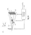
- FIG. 3a shows a representation of a 3D X-ray system 200 with the inventive method for determining the spatial resolution by means of the (above with reference to Fig. 1a described) 3D specimen 10 can be performed.
- the 3D X-ray system 200 has, for example, an X-ray tube 210 and a (planar) detector 230, which is sensitive to X-ray radiation 212, for example in the form of a flat-panel detector or planar X-ray detector.
- the X-radiation 212 exiting from the X-ray source 210 radiates or penetrates the test body 10 and strikes the X-ray-sensitive detector 230.
- the 3D X-ray system 200 is assigned a processing and control device 270 which is used to control the 3D X-ray system 200 including the X-ray source 210 and the X-ray sensitive detector 230, to control the movement of the examination object, ie the test body 10, and also to evaluate the recorded radiographic images is used.
- the X-ray transmission recording has a projection of the three-dimensional volume of the test body 10, wherein the transmission or projection is produced by imaging the X-rays 212 emerging from the X-radiation source 210 after passing through the test body 10 onto the two-dimensional surface 232 of the X-ray sensitive detector 230.
- the x-ray-sensitive detector 230 is designed, for example, as a solid-state detector and can be designed as a line detector, for example in a surface-beam CT or as a multi-line or area detector, for example in a 3D cone-beam CT.
- a line detector for example in a surface-beam CT or as a multi-line or area detector, for example in a 3D cone-beam CT.
- the inventive concept is applicable to any 3D X-ray systems, such as on CL systems, etc.
- the projection data set which serves as the basis for the reconstruction of depth information of the test piece 10 is acquired in one (or more) full revolution (s) of the test piece 10 relative to the X-ray system in small angular steps.
- the 3D X-ray system comprising X-ray source 210 and X-ray detector 230 is rotatably arranged, for example in a CT system, relative to the test body 10.
- a 360 ° complete circle is divided into equidistant angular positions ⁇ , which are approached in turn.
- a 3D image or 3D volume is reconstructed from the plurality of measurement radiographs (from the radiographic data set or projection data set), wherein each one Volume element or voxel of the 3D image is assigned a attenuation coefficient or degree of absorption.
- a mathematical transformation eg radon transformation
- the processing and control device 270 may, for example, be designed to be based on Fig. 2 described method steps of detecting 120 a sequence of radiographic exposures of the specimen at different angular positions, the reconstructing 130 of a 3D X-ray of the specimen based on the total number of measurement radiographs, and the determination 140 of the spatial resolution of the 3D X-ray system to perform or control.
- the processing and control device 270 of the 3D X-ray system may, for example, further comprise an image processing device, eg an image processing software, which automatically generates and outputs the determination of the spatial resolution of the 3D X-ray system based on the blur region of the 3D X-ray image.
- an output or display 270a can be, for example, a determined value for the spatial resolution "l" and / or a representation of the blur region of the 3D x-ray image (cf. Fig. 3b ) exhibit.
- the test specimen 10 according to the invention is placed in the 3D X-ray system so that the entire 3D specimen 10 (EZRT star) is imaged in the reconstructed 3D volume.
- the planes of symmetry of the 3D specimen 10 ie the orthogonally arranged disc structures 12, 14, 16 of the specimen 10 are parallel to the main axes of the 3D X-ray system to be examined.
- the planes of symmetry of the 3D test body 10 can also lie parallel to the main axes of the 3D X-ray system to be examined.
- the orientation or orientation of the test body 10 according to the invention can essentially be chosen arbitrarily.
- one is precise alignment with the 3D X-ray system or with the X-ray source and the X-ray detector of the 3D X-ray system is not required.
- the determination of the spatial resolution capability of the 3D X-ray system may be for any 3D imaging method, i. for each combination of image trajectory and reconstruction method.
- the spatial resolution of the 3D X-ray system can now be determined from the 3D volume data by observing a sectional image in the middle of a pane structure 12, 14, 16 of the test piece 10. The evaluation is then carried out by determining the diameter of the blurred region d in the center of the test body 10.
- the determination can be carried out with all three mutually orthogonal disk structures, whereby the spatial resolution can be determined depending on the respective spatial direction. This is especially true for 3D x-ray systems with anisotropic spatial resolution, i. with different spatial resolutions in different directions, e.g. relevant in computer tomographs with line detectors and slice-by-slice or laminographic capture techniques.
- the resolution within a slice is determined by the X-ray system (source / detector / geometrical arrangement of the components), while the resolution between the individual slices depends primarily on the spacing of the individual slices, which is completely independent the remaining recording parameters can be selected and thus largely independent of the resolution within a layer. If it is intended to detect defects or structures with different linear expansions in different spatial directions with such an X-ray system, the recognizability of the defect or of this structure depends on its orientation, if the plant has anisotropic dissolution properties.
- Fig. 3b now shows two exemplary 3D X-ray images or sectional images by a respective slice structure of the specimen with different resulting spatial resolutions with respect to a spatial direction of a 3D X-ray system.
- the test body 10 can be placed on the turntable of a 3D X-ray system without further preparation, additional infrastructure or adjustment processes.
- the 3D specimen 10 according to the invention may also be placed inside an object of inspection, such as e.g. a motor vehicle or a sea container, etc. are positioned to determine the resulting spatial resolution of the 3D X-ray system.
- test object 10 explained above for determining the spatial resolution of a 3D X-ray system and the method 100 for determining the spatial resolution of a 3D X-ray system using the test body 10 according to the invention thus provide a number of advantages.
- the inventive 3D test specimen (EZRT star) is relatively simple and thus relatively inexpensive to manufacture.
- the evaluation of the 3D specimen 10 is simple and leaves Automate as much as possible, eg by means of image processing equipment, such as image processing software.
- the positioning of the 3D specimen 10 in the object is not critical, since, if necessary, sectional planes can be synthesized by the individual disc structures of the specimen 10 in the 3D volume data.
- the value of the highest spatial resolution can be infinitely determined, this being possible simultaneously in three orthogonal spatial directions based on the recording of a single volume data set of the test specimen.
- aspects of the 3D X-ray system also describe the corresponding method for determining spatial resolution in at least one of represent three orthogonal spatial directions of a 3D X-ray system, so that a block or a component of a device, eg a corresponding 3D X-ray system, is also to be understood as a corresponding method step or as a feature of a method step.
- aspects described in connection with or as a method step also represent a description of a corresponding block or detail or feature of a corresponding device.
- Some or all method steps may also be performed by a hardware device (or using a hardware device ), such as a microprocessor, a programmable computer or an electronic circuit. In some embodiments, some or more of the important method steps may be performed by such an apparatus.
- embodiments of the invention may be implemented in hardware or in software.
- the implementation may be performed using a digital storage medium such as a Blu-ray Disc, a CD, a ROM, a PROM, an EPROM, an EEPROM or FLASH memory, a hard disk, or other magnetic or optical memory, on which electronically readable control signals are stored which can cooperate with or cooperate with a programmable computer system such that the respective method is performed. Therefore, the digital storage medium can be computer readable.
- Some embodiments according to the invention thus comprise a data carrier, comprising electronically readable control signals capable of interacting with a programmable computer system to perform one of the methods described herein.
- embodiments of the present invention may be implemented as a computer program product having a program code, wherein the program code is operable to perform one of the methods when the computer program product runs on a computer.
- the program code can also be stored, for example, on a machine-readable carrier.
- Other embodiments include the computer program for performing any of the methods described herein, wherein the computer program is stored on a machine-readable medium.
- an embodiment of the method according to the invention is thus a computer program which has a program code for performing one of the methods described herein when the computer program runs on a computer.
- a further embodiment of the inventive method is thus a data carrier (or a digital storage medium or a computer-readable medium) on which the computer program is recorded for carrying out one of the methods described herein.
- a further embodiment of the method according to the invention is thus a data stream or a sequence of signals, which represent the computer program for performing one of the methods described herein.
- the data stream or the sequence of signals may be configured, for example, to be transferred via a data communication connection, for example via the Internet.
- Another embodiment includes a processing device, such as a computer or a programmable logic device, that is configured or adapted to perform one of the methods described herein.
- a processing device such as a computer or a programmable logic device
- Another embodiment includes a computer on which the computer program is installed to perform one of the methods described herein.
- Another embodiment according to the invention comprises a device or system designed to at least execute a computer program to transmit one of the methods described herein to a receiver.
- the transmission can be done for example electronically or optically.
- the receiver may be, for example, a computer, a mobile device, a storage device or a similar device.
- the device or system may include a file server for transmitting the computer program to the recipient.
- a programmable logic device eg, a field programmable gate array, an FPGA
- a field programmable gate array may cooperate with a microprocessor to perform one of the methods described herein.
- the methods are performed by any hardware device. This may be a universal hardware such as a computer processor (CPU) or hardware specific to the process, such as an ASIC.
Landscapes
- Health & Medical Sciences (AREA)
- Life Sciences & Earth Sciences (AREA)
- Engineering & Computer Science (AREA)
- Pathology (AREA)
- General Health & Medical Sciences (AREA)
- Physics & Mathematics (AREA)
- Medical Informatics (AREA)
- Nuclear Medicine, Radiotherapy & Molecular Imaging (AREA)
- Radiology & Medical Imaging (AREA)
- Heart & Thoracic Surgery (AREA)
- Veterinary Medicine (AREA)
- Biomedical Technology (AREA)
- High Energy & Nuclear Physics (AREA)
- Molecular Biology (AREA)
- Surgery (AREA)
- Animal Behavior & Ethology (AREA)
- Biophysics (AREA)
- Public Health (AREA)
- Optics & Photonics (AREA)
- Pulmonology (AREA)
- Theoretical Computer Science (AREA)
- Chemical & Material Sciences (AREA)
- Analytical Chemistry (AREA)
- Biochemistry (AREA)
- General Physics & Mathematics (AREA)
- Immunology (AREA)
- Analysing Materials By The Use Of Radiation (AREA)
Applications Claiming Priority (1)
| Application Number | Priority Date | Filing Date | Title |
|---|---|---|---|
| DE102013214482.2A DE102013214482B4 (de) | 2013-07-24 | 2013-07-24 | Prüfkörper für ein 3d-röntgensystem und verfahren zur bestimmung der ortsauflösung eines 3d-röntgensystems mittels des prüfkörpers |
Publications (1)
| Publication Number | Publication Date |
|---|---|
| EP2829232A1 true EP2829232A1 (fr) | 2015-01-28 |
Family
ID=51211706
Family Applications (1)
| Application Number | Title | Priority Date | Filing Date |
|---|---|---|---|
| EP14178229.2A Withdrawn EP2829232A1 (fr) | 2013-07-24 | 2014-07-23 | Éprouvette pour un système radiographique 3D et procédé de détermination de la résolution spatiale d'un système radiographique 3D à l'aide de l'éprouvette |
Country Status (2)
| Country | Link |
|---|---|
| EP (1) | EP2829232A1 (fr) |
| DE (1) | DE102013214482B4 (fr) |
Citations (4)
| Publication number | Priority date | Publication date | Assignee | Title |
|---|---|---|---|---|
| US4055771A (en) * | 1976-10-26 | 1977-10-25 | Alderson Research Laboratories, Inc. | Test body for a scanning tomographic analytical apparatus |
| US20030223550A1 (en) * | 2002-06-03 | 2003-12-04 | Samsung Electronics Co., Ltd. | Radioactive image apparatus and focus control method thereof |
| DE102006032607A1 (de) * | 2006-07-11 | 2008-01-17 | Carl Zeiss Industrielle Messtechnik Gmbh | Anordnung zur Erzeugung elektromagnetischer Strahlung und Verfahren zum Betreiben der Anordnung |
| DE102011001746A1 (de) * | 2011-04-01 | 2012-10-04 | Werth Messtechnik Gmbh | Prüfkörper sowie Verfahren zum Einmessen eines Koordinatenmessgerätes |
Family Cites Families (1)
| Publication number | Priority date | Publication date | Assignee | Title |
|---|---|---|---|---|
| DE102011117859A1 (de) | 2011-11-08 | 2013-05-08 | Fachhochschule Köln | Prüfkörper und Verfahren zur Überprüfung der Übertragungseigenschaften von Volumentomographen |
-
2013
- 2013-07-24 DE DE102013214482.2A patent/DE102013214482B4/de active Active
-
2014
- 2014-07-23 EP EP14178229.2A patent/EP2829232A1/fr not_active Withdrawn
Patent Citations (4)
| Publication number | Priority date | Publication date | Assignee | Title |
|---|---|---|---|---|
| US4055771A (en) * | 1976-10-26 | 1977-10-25 | Alderson Research Laboratories, Inc. | Test body for a scanning tomographic analytical apparatus |
| US20030223550A1 (en) * | 2002-06-03 | 2003-12-04 | Samsung Electronics Co., Ltd. | Radioactive image apparatus and focus control method thereof |
| DE102006032607A1 (de) * | 2006-07-11 | 2008-01-17 | Carl Zeiss Industrielle Messtechnik Gmbh | Anordnung zur Erzeugung elektromagnetischer Strahlung und Verfahren zum Betreiben der Anordnung |
| DE102011001746A1 (de) * | 2011-04-01 | 2012-10-04 | Werth Messtechnik Gmbh | Prüfkörper sowie Verfahren zum Einmessen eines Koordinatenmessgerätes |
Non-Patent Citations (1)
| Title |
|---|
| SASOV, ALEXANDER ET. AL.: "New type of x-ray source for lensless laboratory nano-CTwith 50nm resolution", PROC. SPIE 7804, vol. 7804, 78040Q, 2 September 2010 (2010-09-02), San Diego, California, pages 1 - 8, XP040543563, DOI: 10.1117/12.860340 * |
Also Published As
| Publication number | Publication date |
|---|---|
| DE102013214482A1 (de) | 2015-01-29 |
| DE102013214482B4 (de) | 2021-07-15 |
Similar Documents
| Publication | Publication Date | Title |
|---|---|---|
| EP3548876B1 (fr) | Procédé d'imagerie en tenseur de diffusion en champ sombre | |
| DE69115248T2 (de) | Rechnergesteuerte dreidimensionale tomographische abtastung zur gewinnung von daten von objekten, deren abmessung grösser ist als der strahlungskegel. | |
| EP2263075B1 (fr) | Procédé de mesure tomographique de pièces mécaniques | |
| EP2776818B1 (fr) | Corps d'essai et procédé de vérification des propriétés de transmission de tomographes volumiques | |
| DE102015214071B3 (de) | MPI-Verfahren | |
| DE102014209721A1 (de) | Verfahren zur Bestimmung einer Eigenschaft eines stabförmigen Artikels der Tabak verarbeitenden Industrie mittels Röntgenstrahlung, und Probenhalter | |
| EP2737852A1 (fr) | Procédé de détection des propriétés d'imagerie géométriques d'un détecteur à panneau plat, systèm de test adapté suivant et corps de calibrage | |
| EP2637564A1 (fr) | Dispositif de mesure pour un tomographe assisté par ordinateur | |
| DE102011004598A1 (de) | Verfahren und Computersystem zur Streustrahlkorrektur in einem Multi-Source-CT | |
| DE102012203086A1 (de) | Bildverarbeitungsvorrichtung eines computertomographie-systems | |
| EP2636019B1 (fr) | Procédé et dispositif d'évaluation servant à déterminer la position d'une structure se trouvant dans un objet à examiner au moyen d'une tomographie aux rayons x assistée par ordinateur | |
| DE102013108367A1 (de) | Vorrichtung und Verfahren zur Aufnahme von Durchstrahlungsbildern bei einer Computertomografie | |
| DE102007043820B4 (de) | Verfahren zur Bestimmung eines Korrekturwerts einer Bremsfleckposition einer Röntgenquelle einer Messanordnung sowie eine Messanordnung zum Erzeugen von Durchstrahlungsbildern | |
| DE102005036527B4 (de) | Röntgen-CT-Prüfanlage sowie CT-Verfahren zur Prüfung von Objekten | |
| EP3751261A1 (fr) | Procédé et dispositif d'étalonnage d'un système à rayons x | |
| EP1186855A2 (fr) | Procédé pour l'inspection non destructive de l'épaisseur de paroi | |
| EP3756158B1 (fr) | Procédé pour déterminer des erreurs dans des paramètres dérivés de représentations d'objets numériques | |
| DE102019004607B4 (de) | Ct-rekonstruktionsverfahren unter verwendung einer gefilterten rückprojektion | |
| DE102017222151A1 (de) | Kalibrierung eines Koordinatenmessgeräts, das Messobjekte mit invasiver Strahlung durchstrahlt | |
| DE102013214482B4 (de) | Prüfkörper für ein 3d-röntgensystem und verfahren zur bestimmung der ortsauflösung eines 3d-röntgensystems mittels des prüfkörpers | |
| WO2017133845A1 (fr) | Procédé de reconstruction d'un objet de test lors d'un procédé de tomographie rayons x assistée par ordinateur dans une installation de tomographie rayons x assistée par ordinateur sans manipulateur | |
| DE102010022285A1 (de) | Verfahren zur Bestimmung der optimalen Lage eines Messobjektes bei der 3D-Computertomografie | |
| EP2011082B1 (fr) | Dispositif et procédé d'obtention d'une représentation bidimensionnelle d'une section d'objet disposée de manière quelconque à l'intérieur d'un objet | |
| DE102006028452A1 (de) | Prüfkörper zur Einmessung und Überprüfung von dimensionellen Tomographie-Messgeräten | |
| DE102019103382A1 (de) | Verfahren zur Rekonstruktion einer digitalen Repräsentation von Objektmerkmalen eines Untersuchungsobjekts im Ortsraum eines Röntgensystems |
Legal Events
| Date | Code | Title | Description |
|---|---|---|---|
| 17P | Request for examination filed |
Effective date: 20140723 |
|
| AK | Designated contracting states |
Kind code of ref document: A1 Designated state(s): AL AT BE BG CH CY CZ DE DK EE ES FI FR GB GR HR HU IE IS IT LI LT LU LV MC MK MT NL NO PL PT RO RS SE SI SK SM TR |
|
| AX | Request for extension of the european patent |
Extension state: BA ME |
|
| PUAI | Public reference made under article 153(3) epc to a published international application that has entered the european phase |
Free format text: ORIGINAL CODE: 0009012 |
|
| R17P | Request for examination filed (corrected) |
Effective date: 20150727 |
|
| RBV | Designated contracting states (corrected) |
Designated state(s): AL AT BE BG CH CY CZ DE DK EE ES FI FR GB GR HR HU IE IS IT LI LT LU LV MC MK MT NL NO PL PT RO RS SE SI SK SM TR |
|
| GRAP | Despatch of communication of intention to grant a patent |
Free format text: ORIGINAL CODE: EPIDOSNIGR1 |
|
| STAA | Information on the status of an ep patent application or granted ep patent |
Free format text: STATUS: GRANT OF PATENT IS INTENDED |
|
| INTG | Intention to grant announced |
Effective date: 20170201 |
|
| STAA | Information on the status of an ep patent application or granted ep patent |
Free format text: STATUS: THE APPLICATION IS DEEMED TO BE WITHDRAWN |
|
| 18D | Application deemed to be withdrawn |
Effective date: 20170613 |