EP2829232A1 - Test body for a 3D X-ray system and method for determining the spatial resolution of a 3D X-ray by means of the test body - Google Patents
Test body for a 3D X-ray system and method for determining the spatial resolution of a 3D X-ray by means of the test body Download PDFInfo
- Publication number
- EP2829232A1 EP2829232A1 EP14178229.2A EP14178229A EP2829232A1 EP 2829232 A1 EP2829232 A1 EP 2829232A1 EP 14178229 A EP14178229 A EP 14178229A EP 2829232 A1 EP2829232 A1 EP 2829232A1
- Authority
- EP
- European Patent Office
- Prior art keywords
- ray
- sectors
- disk structure
- spatial resolution
- disc
- Prior art date
- Legal status (The legal status is an assumption and is not a legal conclusion. Google has not performed a legal analysis and makes no representation as to the accuracy of the status listed.)
- Withdrawn
Links
Images



Classifications
-
- G—PHYSICS
- G01—MEASURING; TESTING
- G01N—INVESTIGATING OR ANALYSING MATERIALS BY DETERMINING THEIR CHEMICAL OR PHYSICAL PROPERTIES
- G01N23/00—Investigating or analysing materials by the use of wave or particle radiation, e.g. X-rays or neutrons, not covered by groups G01N3/00 – G01N17/00, G01N21/00 or G01N22/00
- G01N23/02—Investigating or analysing materials by the use of wave or particle radiation, e.g. X-rays or neutrons, not covered by groups G01N3/00 – G01N17/00, G01N21/00 or G01N22/00 by transmitting the radiation through the material
- G01N23/04—Investigating or analysing materials by the use of wave or particle radiation, e.g. X-rays or neutrons, not covered by groups G01N3/00 – G01N17/00, G01N21/00 or G01N22/00 by transmitting the radiation through the material and forming images of the material
- G01N23/046—Investigating or analysing materials by the use of wave or particle radiation, e.g. X-rays or neutrons, not covered by groups G01N3/00 – G01N17/00, G01N21/00 or G01N22/00 by transmitting the radiation through the material and forming images of the material using tomography, e.g. computed tomography [CT]
-
- A—HUMAN NECESSITIES
- A61—MEDICAL OR VETERINARY SCIENCE; HYGIENE
- A61B—DIAGNOSIS; SURGERY; IDENTIFICATION
- A61B6/00—Apparatus or devices for radiation diagnosis; Apparatus or devices for radiation diagnosis combined with radiation therapy equipment
- A61B6/58—Testing, adjusting or calibrating thereof
- A61B6/582—Calibration
- A61B6/583—Calibration using calibration phantoms
-
- A—HUMAN NECESSITIES
- A61—MEDICAL OR VETERINARY SCIENCE; HYGIENE
- A61B—DIAGNOSIS; SURGERY; IDENTIFICATION
- A61B6/00—Apparatus or devices for radiation diagnosis; Apparatus or devices for radiation diagnosis combined with radiation therapy equipment
- A61B6/02—Arrangements for diagnosis sequentially in different planes; Stereoscopic radiation diagnosis
- A61B6/03—Computed tomography [CT]
- A61B6/032—Transmission computed tomography [CT]
-
- G—PHYSICS
- G01—MEASURING; TESTING
- G01N—INVESTIGATING OR ANALYSING MATERIALS BY DETERMINING THEIR CHEMICAL OR PHYSICAL PROPERTIES
- G01N2223/00—Investigating materials by wave or particle radiation
- G01N2223/30—Accessories, mechanical or electrical features
- G01N2223/303—Accessories, mechanical or electrical features calibrating, standardising
- G01N2223/3035—Accessories, mechanical or electrical features calibrating, standardising phantom
Definitions
- the present invention relates to a test specimen for determining the spatial resolution of a 3D X-ray system, to a method for determining the spatial resolution of a 3D X-ray system by means of the specimen and to the use of the specimen for determining the spatial resolution of a 3D X-ray system. More particularly, the present invention relates to a specimen for evaluating the spatial resolution of a 3D X-ray scanner in at least one of three orthogonal spatial directions.
- the test specimen is in this case from an X-ray system by means of a 3D scanning method, such. by means of computer tomography (CT) or computer laminography (CL), whereupon the 3D volume data set is reconstructed. Based on this data set, the spatial resolution of the resulting 3D scan, i. determine the resulting 3D X-ray, in three mutually orthogonal spatial planes.
- CT computer tomography
- CL computer laminography
- test specimens for the simultaneous determination of the spatial resolution of a 3D X-ray system in three spatial directions are all based on so-called beam group tests or hole patterns in a plane, wherein in each spatial direction the spatial resolution must be determined by a separate measurement after prior alignment of the specimen.
- the bar group test patterns are expensive to purchase and can only be correctly positioned in the X-ray arrangement with a very high outlay, since they can be positioned before the measurement and possibly within a container, e.g. of an airfreight container, etc., must be aligned exactly in the plane in which the image quality is then to be quantified from the volume data set.
- the object underlying the present invention is now to provide an improved test specimen for determining the spatial resolution in up to three orthogonal spatial directions of a 3D X-ray system and a corresponding method for determining the spatial resolution.
- test specimen for determining the spatial resolution of a 3D X-ray system according to claim 1 by a method for determining the spatial resolution of a 3D X-ray system according to claim 9 and by the use of the test specimen for determining the spatial resolution of a 3D X-ray system in at least one of three orthogonal spatial directions according to claim 10.
- the core idea of the present invention is to assemble a three-dimensional test specimen of three mutually orthogonal disks or disk structures, wherein the disks or disk structures are in turn composed of pyramid-shaped or truncated pyramid-shaped elements. Due to the tapering (pointed) pyramids, the discs taper towards the middle or central axis. The pyramid-shaped elements are now arranged so that the materials alternate regularly along the circumference of each disc.
- the three-dimensional test specimen can thus have a sequence of several circular or circular ring sectors, which can be formed alternately from different materials.
- adjacent disk structure sectors of a disk structure may alternately comprise a physical disk structure sector and a disk structure sector formed as a material recess.
- the three-dimensional test specimen can thus have a sequence of several circular or circular ring sectors, which can be formed alternately from disk structure sectors and disk structure sector-shaped free spaces.
- any number of materials N can be strung together using, for example, two different materials (ie, material 1, material 2) in adjacent disk sectors.
- material 1, material 2 one half of the sectors comprise the material 1, ie usually a heavy material, such as steel , Non-ferrous metal, heavy metal etc., with a high absorption coefficient (also damping constant or linear attenuation coefficient) for X-radiation, while the other sectors are the material 2, ie a light material such as plastic, Alloy etc., having a low absorption coefficient for X-radiation.
- adjacent disk structure sectors of a disk structure may alternately have a physical disk structure sector (material 1) and a disk structure sector-shaped material recess (or material clearance space).
- a disc structure sector-shaped recess or recess or a clearance
- a disc structure sector-shaped recess or recess or a clearance
- the physical disk structure segments may comprise a material (e.g., a material 1) or different materials from one another.
- the material or materials for the pyramid-shaped or truncated pyramid-shaped elements are now selected so as to in turn the strongest possible contrast in the resulting X-ray image between the physical disc structure sectors and the respective pyramid-shaped or truncated pyramid-shaped recesses (or Free spaces, gaps or gaps). That is, the material (s) for the physical disk structure sectors have a (significantly) higher absorption coefficient (also attenuation constant or linear attenuation coefficient) for X-radiation than the free spaces (e.g., air or ambient atmosphere).
- the three-dimensional test specimen has three mutually orthogonal slices or disc structures, wherein the individual disc structures may have a substantially same structure.
- the disk structures of a test piece may also be designed differently with regard to the selected materials and the structure.
- adjacent disk structure sectors in a disk structure may comprise different materials, while in one of the further disk structures, the adjacent disk structure sectors may alternately comprise a physical disk structure sector and a disk structure sector formed as a material recess.
- Embodiments thus describe a test specimen for determining the spatial resolution of a 3D X-ray system, wherein the test specimen has three orthogonally arranged and interconnected disc structures with a common center.
- Each disc structure has an even number N of pyramidal or truncated pyramidal slice structure sectors that taper toward the common center, with adjacent slice structure sectors having different X-ray absorption characteristics, respectively.
- adjacent disk structure sectors of a disk structure may have different materials.
- adjacent disk structure sectors of a disk structure may alternately comprise a physical disk structure sector and a disk structure sector formed as material recess (or material space).
- Embodiments thus further describe a method for determining the spatial resolution of a 3D X-ray system by means of the test specimen, comprising the following steps: placing the test specimen in a test position between an X-ray source and an X-ray detector of the 3D X-ray system; Detecting a sequence of radiographic exposures of the specimen at different positions (e.g., angular positions or longitudinal positions) to obtain a total number of measurement radiographs; Reconstructing a 3D X-ray image of the specimen based on the total number of measurement radiographs; and determining the spatial resolution of the 3D X-ray system based on the diameter d of a blur area of the 3D X-ray photograph in the center of the test piece, wherein there is no resolution of the individual pane structure sectors within the blur area, and on the number N of pyramid or truncated pyramid shaped disk structure sectors.
- Embodiments also describe the use of the test specimen for determining the spatial resolution of a 3D X-ray system in at least one of three orthogonal spatial directions.
- FIG. 1a shown schematic representation of a test specimen 10 for determining the spatial resolution of a 3D X-ray system (not shown in Fig. 1a ).
- the test specimen 10 for determining the spatial resolution in at least one of three orthogonal spatial directions or in up to three orthogonal spatial directions of a 3D X-ray system comprises three mutually orthogonally arranged and interconnected disc structures 12, 14, 16 with a common center 18.
- Each disc structure 12, 14, 16 has an even number N of pyramidal or truncated pyramid-shaped disk structure sectors 12-N, 14-N, 16-N that taper toward the common center 18.
- the individual disk structure sectors 12-N, 14-N, 16-N can thus be regarded as circular sectors (or circular sectors) or sectors of a regular N-corner.
- an N-gon is considered with equal sides and equal internal angles, which is further isogonal, i. its corners lie equidistant, so under the same central angle on a circle.
- Fig. 1a two of the three mutually orthogonally arranged and interconnected disc structures 12, 14 and 16 in the respective orthogonal spatial directions each have a pyramid or truncated pyramid-shaped disc structure sector in common.
- the test piece 10 can thus be regarded as symmetrical with respect to three orthogonal spatial directions.
- Respective disc structure sectors of a disc structure have different X-ray absorption properties to obtain a contrast in the resulting X-ray image between the adjacent disc structure sectors.
- adjacent slice structure sectors of a slice structure may have different materials or material properties that result in different X-ray absorption characteristics of the adjacent slice structure sectors to obtain the strongest possible contrast in the resulting X-ray image between the adjacent slice structure sectors.
- a material is alternated with a high absorption coefficient for X-radiation and another material with a low absorption coefficient for X-radiation for adjacent sectors.
- the three-dimensional test specimen has a sequence of several circular sectors, which can be formed alternately from different materials.
- any number of materials N can be strung together, for example, in the simplest case, using two different materials (i.e., material 1, material 2) in adjacent disk sectors.
- material 1, material 2 two different materials in adjacent disk sectors.
- one half of the sectors comprise the material 1, i. usually of a heavy material, e.g. Steel, non-ferrous metal, heavy metal, etc., having a high X-ray absorption coefficient while the other sectors are material 2, i.
- a lightweight material such as Plastic, light metal, etc., having a low absorption coefficient for X-rays.
- a plastic material for a disc structure sector for a lightweight material 2
- a polyaryletherketone plastic can be given.
- Each disk structure 12, 14, 16 thus has at least two different and up to N-different materials with X-ray absorption properties.
- the juxtaposed (or adjacent) and mechanically interconnected disk structure sectors are geometrically the same (or identical), ie they have the same geometric dimensions.
- the pyramid or truncated pyramid-shaped disk structure sectors in a plane perpendicular to the radius (starting from the common center 18) of the respective disk structure 12, 14, 16 have a rectangular or square cross-sectional area.
- the base surface and, in the case of a truncated pyramid-shaped pane structure sector, also the top surface, which run perpendicular to the height of the pane structure sectors have, for example, a square or rectangular shape.
- the outside base surface may, for example, be flat and formed in a plane perpendicular to the radius of the respective disk structure.
- the individual sectors of the disk structure will give a regular N-corner.
- the outside base surfaces of the sectors are each rounded and an example, circular outer shape of the respective disc structure results, so that the individual pyramid or truncated pyramid-shaped sectors of the disc structures are formed as circular or circular sectors.
- the disk structures further have a diameter D between opposite bases of the pyramid or truncated pyramidal sectors.
- the test specimen according to the invention can be adapted to the entire range of industrial or medical computed tomography systems or computer laminography systems.
- the pyramid diameters ie the diameters of the pyramidal or truncated pyramid-shaped disk structure sectors, can lie at the common center of the disk structures at the tip in the tenth of a millimeter range, eg for ⁇ CT systems up to the centimeter range for XXL CT systems, if provided is that the "star structure" of the specimen 10 can be manufactured with sufficient accuracy.
- the functionality of the test body 10 according to the invention is based essentially purely on the geometric shape of the test body 10, regardless of the diameter of the star, i. of the slice structures (depending, for example, on the height of the pyramidal or truncated pyramidal sectors) and the number of sectors.
- the disk structure sectors may be pyramid-shaped or pyramidal-shaped, with a small area then being left open in the middle of the disk structures (at the common center 18) in the case of a truncated pyramid-shaped formation.
- At least 16 disc structure sectors may be provided for each disc structure 12, 14, 16.
- the disk structure sectors 12-N, 14-N, 16-N may be truncated-pyramidal, with a length "a" provided from the ground surface to the top surface of the truncated pyramidal disk structure sector.
- the length "a” at least 80% (or 90%) of the distance between the center or centroid of the respective base of the truncated pyramid-shaped Slice structure sectors up to the common center point.
- adjacent disk structure sectors of a disk structure may alternately have a physical disk structure sector and a disk structure sector-shaped space.
- a slice structure sector-shaped space may be provided between two physical slice structure sectors to maintain the array regularly alternating along the circumference of a slice structure ("physical slice structure sector” - "free space” - "physical slice structure sector” - "free space” - etc.).
- the physical disk structure segments can, for example, have a common material or different materials among one another.
- the material or materials for the physical disk structure segments are now selected so as to again achieve the strongest possible contrast in the resulting X-ray image between the physical disk structure sectors and the intervening free spaces. That is, the material (s) for the physical disk structure sectors have a (significantly) higher absorption coefficient (also attenuation constant or linear attenuation coefficient) for X-radiation than the free spaces (e.g., air or ambient atmosphere).
- Embodiments thus further describe a test specimen for determining the spatial resolution of a 3D X-ray system, wherein the test specimen has three orthogonally arranged and interconnected disc structures with a common center.
- Each disk structure has an even number N of pyramidal or truncated pyramid-shaped disk structure sectors that taper toward the common center, with adjacent disk structure sectors of a disk structure alternately having a physical disk structure sector and a disk structure sector formed as a material recess.
- a mechanical connecting element (not shown in FIG Fig. 1 a) the physical disk structure sectors, for example in the area of the common center.
- This mechanical connection element can be formed, for example, by pouring the material cutouts in the region of the common center point 18 in regions.
- "a ring element" (not shown in FIG Fig. 1 a) be provided to mechanically interconnect the bases of the "physical" disc structure sectors of the respective disc structures and to obtain a corresponding mechanical stability of the resulting disc structures and the resulting specimen.
- Fig. 1b now shows in different views a single pyramid or truncated pyramid-shaped slice structure sector of one of the pane structures 12, 14, 16.
- the dimensions and sizes are to be regarded as purely exemplary.
- FIG. 2 illustrated flowchart of a method according to the invention for determining the spatial resolution of a 3D X-ray system using the in Fig. 1a-1b represented 3D specimen and based on the in Fig. 3a-b illustrated exemplary 3D X-ray system for performing the method according to the invention, the concept of the invention for determining the spatial resolution of a 3D X-ray system by means of the inventive 3D specimen explained in more detail.
- X-ray radiation in the form of a fan beam or a cone beam is emitted by an X-ray tube as a radiation source, which penetrates the examination object or test object and falls onto an X-ray detector.
- X-radiation impinges on matter, depending on the material and object condition, e.g. Material density and transmission lengths, a different proportion of the radiation is absorbed by the object to be examined.
- the radiation or projection of the surface of the examination object under a multiplicity of angular or longitudinal positions, a spatial information of the examination subject can be determined. The more projections recorded at different angles or different positions, the more depth information (3D information) is available, which can then be reconstructed from the images.
- CT computed tomography
- CL computer laminography
- CT computed tomography
- the present concept of a probe for determining the spatial resolution of a 3D x-ray system is generally applicable to any 3D scan, i. even if the object is illuminated at several completely arbitrary viewing angles, where no regularity or system is recognizable, as long as positions or orientation of source and detector are known for each individual projection.
- Computed tomography is the special case in which both the X-ray source and the detector move on concentric circles or circle segments and the surface normal of the detector surface always points in the direction of the X-ray source.
- An exception is the so-called helix CT, in which source and detector move on a helical path around a common axis of rotation.
- the special case of computer lamination is the recording trajectories, where the source and the detector move on two coplanar planes, with the object between these coplanar planes.
- the surface normal of the detector is not constantly aligned with the source, but typically shows a constant direction throughout the scan.
- the movement of the two components at these levels is freely selectable (linear, circular, spiral, elliptical, rectangular, etc.).
- the specimen 10 is placed in a test position between an X-ray source and an X-ray detector of the 3D X-ray system (step 110). Thereafter, a sequence of radiographic exposures of the specimen at (eg predetermined) different angular or longitudinal positions is detected (step 120) to obtain a total number of transmission radiographs. Based on the total number of measurement radiographs, a 3D X-ray image (ie, for example, a computed tomography image or computed tomography image) of the specimen is reconstructed based on the total number of measurement radiographs (step 130).
- a 3D X-ray image ie, for example, a computed tomography image or computed tomography image
- the spatial resolution of the 3D X-ray system in at least one spatial plane is based on the diameter d of a (approximately circular) blur region of the 3D X-ray image at the common center or in the center of the test specimen in the respective spatial plane and the number N of pyramidal or truncated pyramidal slice structure sectors (step 140).
- the region of the 3D X-ray image at the common center or in the center of the specimen, within which no resolution or separation of the individual disc structure sectors in the resulting X-ray image is possible or present, is now designated as a blur area.
- the step of determining the spatial resolution can be carried out in one spatial plane or in several orthogonal spatial planes of the 3d x-ray image corresponding to the mutually orthogonal slice structures 12, 14, 16 and can be largely automated, eg by means of an image processing device or image processing software.
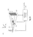
- FIG. 3a shows a representation of a 3D X-ray system 200 with the inventive method for determining the spatial resolution by means of the (above with reference to Fig. 1a described) 3D specimen 10 can be performed.
- the 3D X-ray system 200 has, for example, an X-ray tube 210 and a (planar) detector 230, which is sensitive to X-ray radiation 212, for example in the form of a flat-panel detector or planar X-ray detector.
- the X-radiation 212 exiting from the X-ray source 210 radiates or penetrates the test body 10 and strikes the X-ray-sensitive detector 230.
- the 3D X-ray system 200 is assigned a processing and control device 270 which is used to control the 3D X-ray system 200 including the X-ray source 210 and the X-ray sensitive detector 230, to control the movement of the examination object, ie the test body 10, and also to evaluate the recorded radiographic images is used.
- the X-ray transmission recording has a projection of the three-dimensional volume of the test body 10, wherein the transmission or projection is produced by imaging the X-rays 212 emerging from the X-radiation source 210 after passing through the test body 10 onto the two-dimensional surface 232 of the X-ray sensitive detector 230.
- the x-ray-sensitive detector 230 is designed, for example, as a solid-state detector and can be designed as a line detector, for example in a surface-beam CT or as a multi-line or area detector, for example in a 3D cone-beam CT.
- a line detector for example in a surface-beam CT or as a multi-line or area detector, for example in a 3D cone-beam CT.
- the inventive concept is applicable to any 3D X-ray systems, such as on CL systems, etc.
- the projection data set which serves as the basis for the reconstruction of depth information of the test piece 10 is acquired in one (or more) full revolution (s) of the test piece 10 relative to the X-ray system in small angular steps.
- the 3D X-ray system comprising X-ray source 210 and X-ray detector 230 is rotatably arranged, for example in a CT system, relative to the test body 10.
- a 360 ° complete circle is divided into equidistant angular positions ⁇ , which are approached in turn.
- a 3D image or 3D volume is reconstructed from the plurality of measurement radiographs (from the radiographic data set or projection data set), wherein each one Volume element or voxel of the 3D image is assigned a attenuation coefficient or degree of absorption.
- a mathematical transformation eg radon transformation
- the processing and control device 270 may, for example, be designed to be based on Fig. 2 described method steps of detecting 120 a sequence of radiographic exposures of the specimen at different angular positions, the reconstructing 130 of a 3D X-ray of the specimen based on the total number of measurement radiographs, and the determination 140 of the spatial resolution of the 3D X-ray system to perform or control.
- the processing and control device 270 of the 3D X-ray system may, for example, further comprise an image processing device, eg an image processing software, which automatically generates and outputs the determination of the spatial resolution of the 3D X-ray system based on the blur region of the 3D X-ray image.
- an output or display 270a can be, for example, a determined value for the spatial resolution "l" and / or a representation of the blur region of the 3D x-ray image (cf. Fig. 3b ) exhibit.
- the test specimen 10 according to the invention is placed in the 3D X-ray system so that the entire 3D specimen 10 (EZRT star) is imaged in the reconstructed 3D volume.
- the planes of symmetry of the 3D specimen 10 ie the orthogonally arranged disc structures 12, 14, 16 of the specimen 10 are parallel to the main axes of the 3D X-ray system to be examined.
- the planes of symmetry of the 3D test body 10 can also lie parallel to the main axes of the 3D X-ray system to be examined.
- the orientation or orientation of the test body 10 according to the invention can essentially be chosen arbitrarily.
- one is precise alignment with the 3D X-ray system or with the X-ray source and the X-ray detector of the 3D X-ray system is not required.
- the determination of the spatial resolution capability of the 3D X-ray system may be for any 3D imaging method, i. for each combination of image trajectory and reconstruction method.
- the spatial resolution of the 3D X-ray system can now be determined from the 3D volume data by observing a sectional image in the middle of a pane structure 12, 14, 16 of the test piece 10. The evaluation is then carried out by determining the diameter of the blurred region d in the center of the test body 10.
- the determination can be carried out with all three mutually orthogonal disk structures, whereby the spatial resolution can be determined depending on the respective spatial direction. This is especially true for 3D x-ray systems with anisotropic spatial resolution, i. with different spatial resolutions in different directions, e.g. relevant in computer tomographs with line detectors and slice-by-slice or laminographic capture techniques.
- the resolution within a slice is determined by the X-ray system (source / detector / geometrical arrangement of the components), while the resolution between the individual slices depends primarily on the spacing of the individual slices, which is completely independent the remaining recording parameters can be selected and thus largely independent of the resolution within a layer. If it is intended to detect defects or structures with different linear expansions in different spatial directions with such an X-ray system, the recognizability of the defect or of this structure depends on its orientation, if the plant has anisotropic dissolution properties.
- Fig. 3b now shows two exemplary 3D X-ray images or sectional images by a respective slice structure of the specimen with different resulting spatial resolutions with respect to a spatial direction of a 3D X-ray system.
- the test body 10 can be placed on the turntable of a 3D X-ray system without further preparation, additional infrastructure or adjustment processes.
- the 3D specimen 10 according to the invention may also be placed inside an object of inspection, such as e.g. a motor vehicle or a sea container, etc. are positioned to determine the resulting spatial resolution of the 3D X-ray system.
- test object 10 explained above for determining the spatial resolution of a 3D X-ray system and the method 100 for determining the spatial resolution of a 3D X-ray system using the test body 10 according to the invention thus provide a number of advantages.
- the inventive 3D test specimen (EZRT star) is relatively simple and thus relatively inexpensive to manufacture.
- the evaluation of the 3D specimen 10 is simple and leaves Automate as much as possible, eg by means of image processing equipment, such as image processing software.
- the positioning of the 3D specimen 10 in the object is not critical, since, if necessary, sectional planes can be synthesized by the individual disc structures of the specimen 10 in the 3D volume data.
- the value of the highest spatial resolution can be infinitely determined, this being possible simultaneously in three orthogonal spatial directions based on the recording of a single volume data set of the test specimen.
- aspects of the 3D X-ray system also describe the corresponding method for determining spatial resolution in at least one of represent three orthogonal spatial directions of a 3D X-ray system, so that a block or a component of a device, eg a corresponding 3D X-ray system, is also to be understood as a corresponding method step or as a feature of a method step.
- aspects described in connection with or as a method step also represent a description of a corresponding block or detail or feature of a corresponding device.
- Some or all method steps may also be performed by a hardware device (or using a hardware device ), such as a microprocessor, a programmable computer or an electronic circuit. In some embodiments, some or more of the important method steps may be performed by such an apparatus.
- embodiments of the invention may be implemented in hardware or in software.
- the implementation may be performed using a digital storage medium such as a Blu-ray Disc, a CD, a ROM, a PROM, an EPROM, an EEPROM or FLASH memory, a hard disk, or other magnetic or optical memory, on which electronically readable control signals are stored which can cooperate with or cooperate with a programmable computer system such that the respective method is performed. Therefore, the digital storage medium can be computer readable.
- Some embodiments according to the invention thus comprise a data carrier, comprising electronically readable control signals capable of interacting with a programmable computer system to perform one of the methods described herein.
- embodiments of the present invention may be implemented as a computer program product having a program code, wherein the program code is operable to perform one of the methods when the computer program product runs on a computer.
- the program code can also be stored, for example, on a machine-readable carrier.
- Other embodiments include the computer program for performing any of the methods described herein, wherein the computer program is stored on a machine-readable medium.
- an embodiment of the method according to the invention is thus a computer program which has a program code for performing one of the methods described herein when the computer program runs on a computer.
- a further embodiment of the inventive method is thus a data carrier (or a digital storage medium or a computer-readable medium) on which the computer program is recorded for carrying out one of the methods described herein.
- a further embodiment of the method according to the invention is thus a data stream or a sequence of signals, which represent the computer program for performing one of the methods described herein.
- the data stream or the sequence of signals may be configured, for example, to be transferred via a data communication connection, for example via the Internet.
- Another embodiment includes a processing device, such as a computer or a programmable logic device, that is configured or adapted to perform one of the methods described herein.
- a processing device such as a computer or a programmable logic device
- Another embodiment includes a computer on which the computer program is installed to perform one of the methods described herein.
- Another embodiment according to the invention comprises a device or system designed to at least execute a computer program to transmit one of the methods described herein to a receiver.
- the transmission can be done for example electronically or optically.
- the receiver may be, for example, a computer, a mobile device, a storage device or a similar device.
- the device or system may include a file server for transmitting the computer program to the recipient.
- a programmable logic device eg, a field programmable gate array, an FPGA
- a field programmable gate array may cooperate with a microprocessor to perform one of the methods described herein.
- the methods are performed by any hardware device. This may be a universal hardware such as a computer processor (CPU) or hardware specific to the process, such as an ASIC.
Landscapes
- Health & Medical Sciences (AREA)
- Life Sciences & Earth Sciences (AREA)
- Engineering & Computer Science (AREA)
- Pathology (AREA)
- General Health & Medical Sciences (AREA)
- Physics & Mathematics (AREA)
- Medical Informatics (AREA)
- Nuclear Medicine, Radiotherapy & Molecular Imaging (AREA)
- Radiology & Medical Imaging (AREA)
- Heart & Thoracic Surgery (AREA)
- Veterinary Medicine (AREA)
- Biomedical Technology (AREA)
- High Energy & Nuclear Physics (AREA)
- Molecular Biology (AREA)
- Surgery (AREA)
- Animal Behavior & Ethology (AREA)
- Biophysics (AREA)
- Public Health (AREA)
- Optics & Photonics (AREA)
- Pulmonology (AREA)
- Theoretical Computer Science (AREA)
- Chemical & Material Sciences (AREA)
- Analytical Chemistry (AREA)
- Biochemistry (AREA)
- General Physics & Mathematics (AREA)
- Immunology (AREA)
- Analysing Materials By The Use Of Radiation (AREA)
Abstract
Ein Prüfkörper 10 zur Bestimmung der Ortsauflösung eines 3D-Röntgensystems, weist drei orthogonal zueinander angeordnete und miteinander verbundene Scheibenstrukturen 12, 14, 16 mit einem gemeinsamen Mittelpunkt 18 auf, wobei jede Scheibenstruktur eine geradzahlige Anzahl N von Pyramiden- oder Pyramidenstumpf-förmigen Scheibenstruktursektoren 12-N, 14-N, 16-N aufweist, die sich zu dem gemeinsamen Mittelpunkt hin verjüngen und wobei jeweils benachbarte Scheibenstruktursektoren einer Scheibenstruktur unterschiedliche Röntgenstrahlungsabsorptionseigenschaften aufweisen.A test specimen 10 for determining the spatial resolution of a 3D X-ray system has three orthogonally arranged and interconnected disc structures 12, 14, 16 with a common center 18, each disc structure having an even number N of pyramid or truncated pyramid-shaped disc structure sectors 12-16. N, 14-N, 16-N tapering toward the common center and each adjacent slice structure sectors of a slice structure having different X-ray absorption characteristics.
Description
Die vorliegende Erfindung bezieht sich auf einen Prüfkörper zur Bestimmung der Ortsauflösung eines 3D-Röntgensystems, auf ein Verfahren zur Bestimmung der Ortsauflösung eines 3D-Röntgensystems mittels des Prüfkörpers und auf die Verwendung des Prüfkörpers zur Bestimmung der Ortsauflösung eines 3D-Röntgensystems. Insbesondere bezieht sich die vorliegende Erfindung auf einen Prüfkörper zur Evaluierung des Ortsauflösungsvermögens eines 3D-Röntgenscanners in zumindest einer von drei orthogonalen Raumrichtungen. Der Prüfkörper wird hierbei von einer Röntgenanlage mittels eines 3D-Scanverfahrens, wie z.B. mittels Computertomographie (CT) oder Computerlaminographie (CL), aufgenommen, woraufhin der 3D-Volumendatensatz rekonstruiert wird. Anhand dieses Datensatzes lässt sich das Ortsauflösungsvermögen des resultierenden 3D-Scans, d.h. der resultierenden 3D-Röntgenaufnahme, in drei orthogonal zueinander stehenden Raumebenen bestimmen.The present invention relates to a test specimen for determining the spatial resolution of a 3D X-ray system, to a method for determining the spatial resolution of a 3D X-ray system by means of the specimen and to the use of the specimen for determining the spatial resolution of a 3D X-ray system. More particularly, the present invention relates to a specimen for evaluating the spatial resolution of a 3D X-ray scanner in at least one of three orthogonal spatial directions. The test specimen is in this case from an X-ray system by means of a 3D scanning method, such. by means of computer tomography (CT) or computer laminography (CL), whereupon the 3D volume data set is reconstructed. Based on this data set, the spatial resolution of the resulting 3D scan, i. determine the resulting 3D X-ray, in three mutually orthogonal spatial planes.
Derzeit bekannte Prüfkörper zur simultanen Bestimmung der Ortauflösung einer 3D-Röntgenanlage in drei Raumrichtungen basieren alle auf sogenannten Balkengruppentests oder Lochmustern in einer Ebene, wobei in jeder Raumrichtung die Ortsauflösung durch eine gesonderte Messung nach vorheriger Ausrichtung des Prüfkörpers bestimmt werden muss. Die Balkengruppentestmuster sind insbesondere teuer in der Anschaffung und nur mit einem sehr hohen Aufwand korrekt in der Röntgenanordnung positionierbar, da sie vor der Messung und ggf. innerhalb eines Behältnisses, z.B. eines Luftfrachtcontainers etc., exakt in der Ebene ausgerichtet sein müssen, in der aus dem Volumendatensatz anschließend die Bildqualität quantifiziert werden soll.Currently known test specimens for the simultaneous determination of the spatial resolution of a 3D X-ray system in three spatial directions are all based on so-called beam group tests or hole patterns in a plane, wherein in each spatial direction the spatial resolution must be determined by a separate measurement after prior alignment of the specimen. In particular, the bar group test patterns are expensive to purchase and can only be correctly positioned in the X-ray arrangement with a very high outlay, since they can be positioned before the measurement and possibly within a container, e.g. of an airfreight container, etc., must be aligned exactly in the plane in which the image quality is then to be quantified from the volume data set.
Die der vorliegenden Erfindung zugrunde liegende Aufgabe besteht nun darin, einen verbesserten Prüfkörper zur Bestimmung der Ortsauflösung in bis zu drei orthogonalen Raumrichtungen eines 3D-Röntgensystems und ein entsprechendes Verfahren zur Bestimmung der Ortsauflösung zu schaffen.The object underlying the present invention is now to provide an improved test specimen for determining the spatial resolution in up to three orthogonal spatial directions of a 3D X-ray system and a corresponding method for determining the spatial resolution.
Diese Aufgabe wird durch einen Prüfkörper zur Bestimmung der Ortsauflösung eines 3D-Röntgensystems gemäß Anspruch 1, durch ein Verfahren zur Bestimmung der Ortsauflösung eines 3D-Röntgensystems gemäß Anspruch 9 und durch die Verwendung des Prüfkörpers zur Bestimmung der Ortsauflösung eines 3D-Röntgensystems in zumindest einer von drei orthogonalen Raumrichtungen gemäß Anspruch 10 gelöst.This object is achieved by a test specimen for determining the spatial resolution of a 3D X-ray system according to
Erfindungsgemäße Weiterbildungen sind in den Unteransprüchen definiert.Inventive developments are defined in the subclaims.
Der Kerngedanke der vorliegenden Erfindung besteht nun darin, einen dreidimensionalen Prüfkörper aus drei aufeinander orthogonal stehenden Scheiben bzw. Scheibenstrukturen zusammenzusetzen, wobei die Scheiben bzw. Scheibenstrukturen wiederum aus Pyramiden-förmigen bzw. Pyramidenstumpf-förmigen Elementen zusammengesetzt sind. Aufgrund der sich verjüngenden (spitz zulaufenden) Pyramiden verjüngen sich die Scheiben zur Mitte bzw. Mittelachse hin. Die Pyramiden-förmigen Elemente sind nun so angeordnet, dass sich entlang des Umfangs einer jeden Scheibe die Materialien regelmäßig abwechseln.The core idea of the present invention is to assemble a three-dimensional test specimen of three mutually orthogonal disks or disk structures, wherein the disks or disk structures are in turn composed of pyramid-shaped or truncated pyramid-shaped elements. Due to the tapering (pointed) pyramids, the discs taper towards the middle or central axis. The pyramid-shaped elements are now arranged so that the materials alternate regularly along the circumference of each disc.
Im Fall von zwei Materialien bedeutet dies, dass sich diese beiden unterschiedlichen Werkstoffe jeweils abwechseln. Der dreidimensionale Prüfkörper kann also eine Aneinanderreihung mehrerer Kreis- oder Kreisringsektoren aufweisen, die abwechselnd aus verschiedenen Materialien gebildet sein können.In the case of two materials, this means that these two different materials alternate in each case. The three-dimensional test specimen can thus have a sequence of several circular or circular ring sectors, which can be formed alternately from different materials.
Ferner können benachbarte Scheibenstruktursektoren einer Scheibenstruktur abwechselnd einen physischen Scheibenstruktursektor und einen als Materialaussparung ausgebildeten Scheibenstruktursektor aufweisen. Der dreidimensionale Prüfkörper kann also eine Aneinanderreihung mehrerer Kreis- oder Kreisringsektoren aufweisen, die abwechselnd aus Scheibenstruktursektoren und Scheibenstruktursektor-förmigen Freiräumen gebildet sein können.Further, adjacent disk structure sectors of a disk structure may alternately comprise a physical disk structure sector and a disk structure sector formed as a material recess. The three-dimensional test specimen can thus have a sequence of several circular or circular ring sectors, which can be formed alternately from disk structure sectors and disk structure sector-shaped free spaces.
Ganz allgemein kann eine beliebige Anzahl von Materialien N aneinandergereiht werden, wobei beispielsweise zwei verschiedene Werkstoffe (d.h. Material 1, Material 2) in benachbarten Scheibensektoren eingesetzt werden. Um nun einen möglichst starken Kontrast im resultierenden Röntgenbild zwischen den verschiedenen Materialien der Sektoren und damit zwischen den einzelnen Sektoren zu erzielen, weist im Fall von N = 2 die eine Hälfte der Sektoren das Material 1 auf, d.h. üblicherweise ein schweres Material, wie z.B. Stahl, Buntmetall, Schwermetall etc., mit einem hohen Absorptionskoeffizienten (auch Dämpfungskonstante oder linearer Schwächungskoeffizient) für Röntgenstrahlung, während die anderen Sektoren das Material 2, d.h. ein leichtes Material wie z.B. Kunststoff, Leichtmetall etc., mit einem niedrigen Absorptionskoeffizienten für Röntgenstrahlung aufweisen.In general, any number of materials N can be strung together using, for example, two different materials (ie,
Alternativ können benachbarte Scheibenstruktursektoren einer Scheibenstruktur abwechselnd einen physischen Scheibenstruktursektor (Material 1) und eine Scheibenstruktursektor-förmige Materialaussparung (bzw. einen Materialfreiraum- oder Zwischenraum) aufweisen. Somit kann zwischen zwei Pyramiden-förmig bzw. Pyramidenstumpf-förmig ausgebildeten, physischen Elementen (Scheibenstruktursektoren) eine Scheibenstruktursektor-förmige Aussparung oder Ausnehmung (bzw. ein Freiraum) vorgesehen sein, um die entlang des Umfangs einer Scheibenstruktur regelmäßig abwechselnde Anordnung ("physischer Scheibenstruktursektor" - "Freiraum" - "physischer Scheibenstruktursektor" - "Freiraum" - etc.) zu erhalten.Alternatively, adjacent disk structure sectors of a disk structure may alternately have a physical disk structure sector (material 1) and a disk structure sector-shaped material recess (or material clearance space). Thus, between two pyramidal or truncated pyramid-shaped physical elements (disc structure sectors) a disc structure sector-shaped recess or recess (or a clearance) may be provided in order to keep the arrangement alternating regularly along the circumference of a disc structure ("physical disc structure sector"). - "free space" - "physical disk structure sector" - "free space" - etc.) to obtain.
Die physischen Scheibenstruktursegmente können beispielsweise einen Werkstoff (z.B. ein Material 1) oder untereinander auch unterschiedliche Werkstoffe aufweisen. Das Material bzw. die Materialien für die Pyramiden-förmigen bzw. Pyramidenstumpf-förmigen Elemente sind nun so gewählt, um wiederum einen möglichst starken Kontrast im resultierenden Röntgenbild zwischen den physischen Scheibenstruktursektoren und den jeweils dazwischenliegenden Pyramiden-förmigen bzw. Pyramidenstumpf-förmigen Aussparungen (bzw. Freiräumen, Leerstellen oder Lücken) zu erzielen. D.h., das Material bzw. die Materialien für die physischen Scheibenstruktursektoren weisen einen (deutlich) höheren Absorptionskoeffizienten (auch Dämpfungskonstante oder linearer Schwächungskoeffizient) für Röntgenstrahlung als die Freiräume (z.B. Luft oder Umgebungsatmosphäre) auf.For example, the physical disk structure segments may comprise a material (e.g., a material 1) or different materials from one another. The material or materials for the pyramid-shaped or truncated pyramid-shaped elements are now selected so as to in turn the strongest possible contrast in the resulting X-ray image between the physical disc structure sectors and the respective pyramid-shaped or truncated pyramid-shaped recesses (or Free spaces, gaps or gaps). That is, the material (s) for the physical disk structure sectors have a (significantly) higher absorption coefficient (also attenuation constant or linear attenuation coefficient) for X-radiation than the free spaces (e.g., air or ambient atmosphere).
Der dreidimensionale Prüfkörper weist drei aufeinander orthogonal stehende Scheiben bzw. Scheibenstrukturen auf, wobei die einzelnen Scheibenstrukturen einen im Wesentlichen gleichen Aufbau aufweisen können. Alternativ können die Scheibenstrukturen eines Prüfkörpers hinsichtlich der gewählten Materialien und des Aufbaus auch unterschiedlich ausgebildet sein. So können benachbarte Scheibenstruktursektoren bei einer Scheibenstruktur unterschiedliche Materialien aufweisen, während bei einer der weiteren Scheibenstrukturen die benachbarten Scheibenstruktursektoren abwechselnd einen physischen Scheibenstruktursektor und einen als Materialaussparung ausgebildeten Scheibenstruktursektor aufweisen können.The three-dimensional test specimen has three mutually orthogonal slices or disc structures, wherein the individual disc structures may have a substantially same structure. Alternatively, the disk structures of a test piece may also be designed differently with regard to the selected materials and the structure. Thus, adjacent disk structure sectors in a disk structure may comprise different materials, while in one of the further disk structures, the adjacent disk structure sectors may alternately comprise a physical disk structure sector and a disk structure sector formed as a material recess.
Ausführungsbeispiele beschreiben somit einen Prüfkörper zur Bestimmung der Ortsauflösung eines 3D-Röntgensystems, wobei der Prüfkörper drei orthogonal zueinander angeordnete und miteinander verbundene Scheibenstrukturen mit einem gemeinsamen Mittelpunkt aufweist. Jede Scheibenstruktur weist eine geradzahlige Anzahl N von Pyramidenoder Pyramidenstumpf-förmigen Scheibenstruktursektoren auf, die sich zu dem gemeinsamen Mittelpunkt hin verjüngen, wobei jeweils benachbarte Scheibenstruktursektoren unterschiedliche Röntgenstrahlungsabsorptionseigenschaften aufweisen. Dabei können benachbarte Scheibenstruktursektoren einer Scheibenstruktur unterschiedliche Materialien aufweisen. Ferner (alternativ oder zusätzlich) können benachbarte Scheibenstruktursektoren einer Scheibenstruktur abwechselnd einen physischen Scheibenstruktursektor und einen als Materialaussparung (bzw. Materialfreiraum) ausgebildeten Scheibenstruktursektor aufweisen.Embodiments thus describe a test specimen for determining the spatial resolution of a 3D X-ray system, wherein the test specimen has three orthogonally arranged and interconnected disc structures with a common center. Each disc structure has an even number N of pyramidal or truncated pyramidal slice structure sectors that taper toward the common center, with adjacent slice structure sectors having different X-ray absorption characteristics, respectively. In this case, adjacent disk structure sectors of a disk structure may have different materials. Further (alternatively or additionally), adjacent disk structure sectors of a disk structure may alternately comprise a physical disk structure sector and a disk structure sector formed as material recess (or material space).
Ausführungsbeispiele beschreiben somit ferner ein Verfahren zur Bestimmung der Ortsauflösung eines 3D-Röntgensystems mittels des Prüfkörpers, mit folgenden Schritten: Platzieren des Prüfkörpers in einer Prüfposition zwischen einer Röntgenquelle und einem Röntgendetektor des 3D-Röntgensystems; Erfassen einer Abfolge von Durchstrahlungsaufnahmen des Prüfkörpers an unterschiedlichen Positionen (z.B. Winkelpositionen oder Längspositionen), um eine Gesamtzahl von Mess-Durchstrahlungsaufnahmen zu erhalten; Rekonstruieren einer 3D-Röntgenaufnahme des Prüfkörpers basierend auf der Gesamtzahl von Mess-Durchstrahlungsaufnahmen; und Bestimmen der Ortsauflösung des 3D-Röntgensystems basierend auf dem Durchmesser d eines Unschärfe-Bereichs der 3D-Röntgenaufnahme im Zentrum des Prüfkörpers, wobei innerhalb des Unschärfe-Bereichs keine Auflösung der einzelnen Scheibenstruktursektoren vorliegt, und auf der Anzahl N von Pyramiden- oder Pyramidenstumpf-förmigen Scheibenstruktursektoren.Embodiments thus further describe a method for determining the spatial resolution of a 3D X-ray system by means of the test specimen, comprising the following steps: placing the test specimen in a test position between an X-ray source and an X-ray detector of the 3D X-ray system; Detecting a sequence of radiographic exposures of the specimen at different positions (e.g., angular positions or longitudinal positions) to obtain a total number of measurement radiographs; Reconstructing a 3D X-ray image of the specimen based on the total number of measurement radiographs; and determining the spatial resolution of the 3D X-ray system based on the diameter d of a blur area of the 3D X-ray photograph in the center of the test piece, wherein there is no resolution of the individual pane structure sectors within the blur area, and on the number N of pyramid or truncated pyramid shaped disk structure sectors.
Die Ortsauflösung "l" des 3D-Röntgensystems wird beispielsweise basierend auf der folgenden Beziehung ermittelt: 
mit dem Durchmesser d des Unschärfe-Bereichs der 3D-Röntgenaufnahme im Zentrum des Prüfkörpers und der Anzahl N von Scheibenstruktursektoren pro Scheibenstruktur.The spatial resolution "l" of the 3D X-ray system is determined, for example, based on the following relationship:
with the diameter d of the blur area of the 3D X-ray photograph in the center of the specimen and the number N of disc structure sectors per disc structure.
Ausführungsbeispiele beschreiben ferner die Verwendung des Prüfkörpers zur Bestimmung der Ortsauflösung eines 3D-Röntgensystems in zumindest einer von drei orthogonalen Raumrichtungen.Embodiments also describe the use of the test specimen for determining the spatial resolution of a 3D X-ray system in at least one of three orthogonal spatial directions.
Bevorzugte Ausführungsbeispiele der vorliegenden Erfindung werden nachfolgend Bezug nehmend auf die beiliegenden Zeichnungen näher erläutert. Es zeigen:
- Fig. 1a
- eine Prinzipdarstellung des Prüfkörpers zur Bestimmung der Ortsauflösung eines 3D-Röntgensystems gemäß einem Ausführungsbeispiel der vorliegenden Erfindung;
- Fig. 1b
- eine Prinzipdarstellung in mehreren Ansichten eines einzelnen Scheibensektors des Prüfkörpers mit einer beispielhaften Bemaßung gemäß einem Ausführungsbeispiel der vorliegenden Erfindung;
- Fig. 2
- ein Flussdiagramm eines Verfahrens zur Bestimmung der Ortsauflösung eines 3D-Röntgensystems mittels des Prüfkörpers in zumindest einer von drei orthogonalen Raumrichtungen gemäß einem Ausführungsbeispiel der vorliegenden Erfindung; und
- Fig. 3a
- eine Prinzipdarstellung eines 3D-Röntgensystems zur Durchführung des erfindungsgemäßen Verfahrens zur Bestimmung der Ortsauflösung des 3D-Röntgensystems gemäß einem Ausführungsbeispiel der vorliegenden Erfindung; und
- Fig. 3b
- beispielhafte 3D-Röntgenaufnahmen mit unterschiedlich resultierenden Ortsauflösungen hinsichtlich einer Raumrichtung des 3D-Röntgensystems.
- Fig. 1a
- a schematic representation of the test specimen for determining the spatial resolution of a 3D X-ray system according to an embodiment of the present invention;
- Fig. 1b
- a schematic representation in several views of a single disc sector of the specimen with an exemplary dimension according to an embodiment of the present invention;
- Fig. 2
- a flowchart of a method for determining the spatial resolution of a 3D X-ray system by means of the test specimen in at least one of three orthogonal spatial directions according to an embodiment of the present invention; and
- Fig. 3a
- a schematic diagram of a 3D X-ray system for performing the method according to the invention for determining the spatial resolution of the 3D X-ray system according to an embodiment of the present invention; and
- Fig. 3b
- exemplary 3D X-ray images with different resulting spatial resolutions with respect to a spatial direction of the 3D X-ray system.
Bevor nachfolgend Ausführungsbeispiele der vorliegenden Erfindung im Detail anhand der Zeichnungen näher erläutert werden, wird darauf hingewiesen, dass identische, funktionsgleiche oder gleichwirkende Elemente, Objekte und/oder Strukturen in den unterschiedlichen Figuren mit den gleichen Bezugszeichen versehen sind, so dass die in den unterschiedlichen Ausführungsbeispielen dargestellte Beschreibung dieser Elemente untereinander austauschbar ist bzw. aufeinander angewendet werden kann.Before embodiments of the present invention are explained in more detail in detail with reference to the drawings, it is pointed out that identical, functionally identical or equivalent elements, objects and / or structures in the different figures are provided with the same reference numerals, so that in the different embodiments Described description of these elements is interchangeable or can be applied to each other.
Im Folgenden wird nun anhand der in
Der Prüfkörper 10 zur Bestimmung der Ortsauflösung in zumindest einer von drei orthogonalen Raumrichtungen bzw. in bis zu drei orthogonalen Raumrichtungen eines 3DRöntgensystems umfasst drei orthogonal zueinander angeordnete und miteinander verbundene Scheibenstrukturen 12, 14, 16 mit einem gemeinsamen Mittelpunkt 18. Jede Scheibenstruktur 12, 14, 16 weist eine geradzahlige Anzahl N von Pyramiden- oder Pyramidenstumpf-förmigen Scheibenstruktursektoren 12-N, 14-N, 16-N auf, die sich zu dem gemeinsamen Mittelpunkt 18 hin verjüngen. Die einzelnen Scheibenstruktursektoren 12-N, 14-N, 16-N können somit als Kreissektoren (bzw. Kreisringsektoren) oder Sektoren eines regelmäßigen N-Ecks angesehen werden. Als regelmäßiges oder reguläres N-Eck wird im Rahmen der vorliegenden Beschreibung ein N-Eck mit gleichen Seiten und gleichen Innenwinkeln angesehen, das ferner isogonal ist, d.h. seine Ecken liegen gleichabständig, also unter gleichem Zentriwinkel auf einem Kreis.The
Wie aus
Jeweils benachbarte Scheibenstruktursektoren einer Scheibenstruktur weisen unterschiedliche Röntgenstrahlungsabsorptionseigenschaften auf, um einen Kontrast im resultierenden Röntgenbild zwischen den benachbarten Scheibenstruktursektoren zu erhalten.Respective disc structure sectors of a disc structure have different X-ray absorption properties to obtain a contrast in the resulting X-ray image between the adjacent disc structure sectors.
Somit können beispielsweise benachbarte Scheibenstruktursektoren einer Scheibenstruktur unterschiedliche Materialien oder Materialeigenschaften aufweisen, die zu unterschiedlichen Röntgenstrahlungsabsorptionseigenschaften der benachbarten Scheibenstruktursektoren führen, um einen möglichst starken Kontrast im resultierenden Röntgenbild zwischen den benachbarten Scheibenstruktursektoren zu erhalten.Thus, for example, adjacent slice structure sectors of a slice structure may have different materials or material properties that result in different X-ray absorption characteristics of the adjacent slice structure sectors to obtain the strongest possible contrast in the resulting X-ray image between the adjacent slice structure sectors.
Um nun einen möglichst starken Kontrast im resultierenden Röntgenbild zwischen den verschiedenen, benachbarten Sektoren zu erzielen, wird abwechselnd ein Material mit einem hohen Absorptionskoeffizienten für Röntgenstrahlung und ein weiteres Material mit einem niedrigen Absorptionskoeffizienten für Röntgenstrahlung für benachbarte Sektoren eingesetzt.In order to achieve the strongest possible contrast in the resulting X-ray image between the different, adjacent sectors, a material is alternated with a high absorption coefficient for X-radiation and another material with a low absorption coefficient for X-radiation for adjacent sectors.
Der dreidimensionale Prüfkörper weist also eine Aneinanderreihung mehrerer Kreissektoren auf, die abwechselnd aus verschiedenen Materialien gebildet sein können. Ganz allgemein kann eine beliebige Anzahl von Materialien N aneinandergereiht werden, wobei beispielsweise im einfachsten Fall zwei verschiedene Werkstoffe (d.h. Material 1, Material 2) in benachbarten Scheibensektoren eingesetzt werden. Um nun einen möglichst starken Kontrast im resultierenden Röntgenbild zwischen den verschiedenen Materialien der Sektoren und damit zwischen den einzelnen Sektoren zu erzielen, weist im Fall von N = 2 die eine Hälfte der Sektoren das Material 1 auf, d.h. üblicherweise aus einem schweren Material, wie z.B. Stahl, Buntmetall, Schwermetall etc., mit einem hohen Absorptionskoeffizienten für Röntgenstrahlung, während die anderen Sektoren das Material 2, d.h. ein leichtes Material wie z.B. Kunststoff, Leichtmetall etc., mit einem niedrigen Absorptionskoeffizienten für Röntgenstrahlung aufweisen. Als Kunststoffmaterial für einen Scheibenstruktursektor (für ein leichtes Material 2) kann beispielsweise ein Polyaryletherketon-Kunststoff angegeben werden.Thus, the three-dimensional test specimen has a sequence of several circular sectors, which can be formed alternately from different materials. In general, any number of materials N can be strung together, for example, in the simplest case, using two different materials (i.e.,
Jede Scheibenstruktur 12, 14, 16 weist somit zumindest zwei unterschiedliche und bis zu N-unterschiedliche Materialien mit Röntgenstrahlabsorptionseigenschaften auf.Each
Wie dies in
Es ist gleichermaßen möglich, dass die außenseitigen Grundflächen der Sektoren jeweils abgerundet sind und sich eine beispielsweise kreisförmige Außenform der jeweiligen Scheibenstruktur ergibt, so dass die einzelnen Pyramiden- oder Pyramidenstumpf-förmigen Sektoren der Scheibenstrukturen als Kreis- oder Kreisringsektoren ausgebildet sind. Die Scheibenstrukturen weisen ferner ein Durchmesser D zwischen gegenüberliegenden Grundflächen der Pyramiden- oder Pyramidenstumpf-förmigen Sektoren auf.It is equally possible that the outside base surfaces of the sectors are each rounded and an example, circular outer shape of the respective disc structure results, so that the individual pyramid or truncated pyramid-shaped sectors of the disc structures are formed as circular or circular sectors. The disk structures further have a diameter D between opposite bases of the pyramid or truncated pyramidal sectors.
Bezüglich der in
Somit kann angegeben werden, dass die Funktionalität des erfindungsgemäßen Prüfkörpers 10 im Wesentlichen rein auf der geometrischen Form des Prüfkörpers 10 basiert, unabhängig vom jeweiligen Durchmesser des Sterns, d.h. der Scheibenstrukturen (abhängig z.B. von der Höhe der Pyramiden- oder Pyramidenstumpf-förmigen Sektoren) und der Anzahl der Sektoren. Die Scheibenstruktursektoren können Pyramiden-förmig oder auch Pyramidenstumpf-förmig ausgebildet sein, wobei im Falle einer Pyramidenstumpf-förmigen Ausbildung in der Mitte der Scheibenstrukturen (an dem gemeinsamen Mittelpunkt 18) dann ein kleiner Bereich freigelassen wird.Thus, it can be stated that the functionality of the
Beispielsweise können für jede Scheibenstruktur 12, 14, 16 zumindest 16 Scheibenstruktursektoren vorgesehen sein.For example, at least 16 disc structure sectors may be provided for each
Wie bereits oben angegeben wurde, können die Scheibenstruktursektoren 12-N, 14-N, 16-N Pyramidenstumpf-förmig ausgebildet sein, wobei eine Länge "a" ausgehend von der Grundfläche bis zu der Deckfläche des Pyramidenstumpf-förmigen Scheibenstruktursektors vorgesehen ist. Dabei weist die Länge "a" zumindest 80% (oder 90%) des Abstandes zwischen dem Mittelpunkt oder Flächenschwerpunkt der jeweiligen Grundfläche der Py-ramidenstumpf-förmigen Scheibenstruktursektoren bis zu dem gemeinsamen Mittelpunkt auf.As stated above, the disk structure sectors 12-N, 14-N, 16-N may be truncated-pyramidal, with a length "a" provided from the ground surface to the top surface of the truncated pyramidal disk structure sector. In this case, the length "a" at least 80% (or 90%) of the distance between the center or centroid of the respective base of the truncated pyramid-shaped Slice structure sectors up to the common center point.
Alternativ können benachbarte Scheibenstruktursektoren einer Scheibenstruktur abwechselnd einen physischen Scheibenstruktursektor und einen Scheibenstruktursektor-förmigen Freiraum aufweisen. Somit kann zwischen zwei physischen Scheibenstruktursektoren ein Scheibenstruktursektor-förmiger Freiraum vorgesehen sein, um die entlang des Umfangs einer Scheibenstruktur regelmäßig abwechselnde Anordnung ("physischer Scheibenstruktursektor" - "Freiraum" - "physischer Scheibenstruktursektor" - "Freiraum" - etc.) zu erhalten.Alternatively, adjacent disk structure sectors of a disk structure may alternately have a physical disk structure sector and a disk structure sector-shaped space. Thus, a slice structure sector-shaped space may be provided between two physical slice structure sectors to maintain the array regularly alternating along the circumference of a slice structure ("physical slice structure sector" - "free space" - "physical slice structure sector" - "free space" - etc.).
Die physischen Scheibenstruktursegmente können beispielsweise einen gemeinsamen Werkstoff oder untereinander auch unterschiedliche Werkstoffe aufweisen. Das Material bzw. die Materialien für die physischen Scheibenstruktursegmente sind nun so gewählt, um wiederum einen möglichst starken Kontrast im resultierenden Röntgenbild zwischen den physischen Scheibenstruktursektoren und den jeweils dazwischenliegenden Freiräumen zu erzielen. D.h., das Material bzw. die Materialien für die physischen Scheibenstruktursektoren weisen einen (deutlich) höheren Absorptionskoeffizienten (auch Dämpfungskonstante oder linearer Schwächungskoeffizient) für Röntgenstrahlung als die Freiräume (z.B. Luft oder Umgebungsatmosphäre) auf.The physical disk structure segments can, for example, have a common material or different materials among one another. The material or materials for the physical disk structure segments are now selected so as to again achieve the strongest possible contrast in the resulting X-ray image between the physical disk structure sectors and the intervening free spaces. That is, the material (s) for the physical disk structure sectors have a (significantly) higher absorption coefficient (also attenuation constant or linear attenuation coefficient) for X-radiation than the free spaces (e.g., air or ambient atmosphere).
Ausführungsbeispiele beschreiben somit ferner einen Prüfkörper zur Bestimmung der Ortsauflösung eines 3D-Röntgensystems, wobei der Prüfkörper drei orthogonal zueinander angeordnete und miteinander verbundene Scheibenstrukturen mit einem gemeinsamen Mittelpunkt aufweist. Jede Scheibenstruktur weist eine geradzahlige Anzahl N von Pyramiden- oder Pyramidenstumpf-förmigen Scheibenstruktursektoren auf, die sich zu dem gemeinsamen Mittelpunkt hin verjüngen, wobei benachbarte Scheibenstruktursektoren einer Scheibenstruktur abwechselnd einen physischen Scheibenstruktursektor und einen als Materialaussparung ausgebildeten Scheibenstruktursektor aufweisen.Embodiments thus further describe a test specimen for determining the spatial resolution of a 3D X-ray system, wherein the test specimen has three orthogonally arranged and interconnected disc structures with a common center. Each disk structure has an even number N of pyramidal or truncated pyramid-shaped disk structure sectors that taper toward the common center, with adjacent disk structure sectors of a disk structure alternately having a physical disk structure sector and a disk structure sector formed as a material recess.
Die im Vorhergehenden hinsichtlich
Um nun eine mechanische Verbindung der physischen Scheibenstruktursektoren und damit die mechanische Stabilität der resultierenden Scheibenstrukturen 12, 14, 16 untereinander und auch des zusammengefügten Prüfkörper zu erhalten, kann ein mechanisches Verbindungselement (nicht gezeigt in
Die oben dargestellten mechanischen Verbindungsmöglichkeiten der unterschiedlichen Scheibenstruktursektoren sind nur als beispielhaft anzusehen, wobei eine beliebige mechanische Verbindung der einzelnen Scheibenstruktursektoren der Scheibenstrukturen gewählt werden kann, um einen mechanisch stabil zusammengesetzten Prüfkörper zu erhalten.The above-described mechanical connection options of the different disk structure sectors are to be considered as exemplary only, with any mechanical connection of the individual disk structure sectors of the disk structures can be selected to obtain a mechanically stable composite test specimen.
Im Folgenden wird nun anhand des in
Bei 3D-Röntgensystemen wird von einer Röntgenröhre als Strahlungsquelle Röntgenstrahlung in Form eines Fächerstrahls oder eines Kegelstrahls abgestrahlt, die das Untersuchungsobjekt bzw. Prüfobjekt durchdringt und auf einen Röntgendetektor fällt. Entsprechend dem Prinzip eines 3D-Röntgensystemen trifft Röntgenstrahlung auf Materie, wobei je nach Material- und Objektbeschaffenheit, z.B. Materialdichte und Durchstrahlungslängen, ein unterschiedlich großer Anteil der Strahlung von dem Untersuchungsobjekt absorbiert wird. Mittels der Durchstrahlung bzw. Projektion der Fläche des Untersuchungsobjekts unter einer Vielzahl von Winkel- oder Längspositionen lässt sich eine räumliche Information des Untersuchungsobjekts ermitteln. Je mehr Projektionen unter unterschiedlichen Winkeln oder unterschiedlichen Positionen aufgenommen werden, umso mehr Tiefeninformationen (3D-Informationen) liegen vor, die man dann aus den Aufnahmen rekonstruieren kann.In the case of 3D X-ray systems, X-ray radiation in the form of a fan beam or a cone beam is emitted by an X-ray tube as a radiation source, which penetrates the examination object or test object and falls onto an X-ray detector. According to the principle of a 3D X-ray system, X-radiation impinges on matter, depending on the material and object condition, e.g. Material density and transmission lengths, a different proportion of the radiation is absorbed by the object to be examined. By means of the radiation or projection of the surface of the examination object under a multiplicity of angular or longitudinal positions, a spatial information of the examination subject can be determined. The more projections recorded at different angles or different positions, the more depth information (3D information) is available, which can then be reconstructed from the images.
Beispielsweise stellen die Computertomographie (CT) und die Computerlaminographie (CL) häufig verwendete spezielle Aufnahmetrajektorien dar. Das vorliegende Konzept eines Prüfkörpers zur Bestimmung der Ortsauflösung eines 3D-Röntgensystems ist aber allgemein auf jegliche 3D-Scans anwendbar, d.h. auch wenn das Objekt unter mehreren völlig willkürlichen Betrachtungswinkeln durchleuchtet wird, bei denen keine Regelmäßigkeit oder ein System erkennbar ist, so lange Positionen bzw. Orientierung von Quelle und Detektor für jede einzelne Projektion bekannt sind. Die Computertomographie bildet den Spezialfall ab, bei dem sowohl die Röntgenquelle als auch der Detektor sich auf konzentrischen Kreisen oder Kreissegmenten bewegen und die Flächennormale der Detektoroberfläche immer in Richtung der Röntgenquelle zeigt. Ausnahme ist die sogenannte Helix-CT, bei sich Quelle und Detektor auf einer Schraubenbahn (Helix) um eine gemeinsame Rotationsachse bewegen.For example, computed tomography (CT) and computer laminography (CL) are commonly used special imaging trajectories. However, the present concept of a probe for determining the spatial resolution of a 3D x-ray system is generally applicable to any 3D scan, i. even if the object is illuminated at several completely arbitrary viewing angles, where no regularity or system is recognizable, as long as positions or orientation of source and detector are known for each individual projection. Computed tomography is the special case in which both the X-ray source and the detector move on concentric circles or circle segments and the surface normal of the detector surface always points in the direction of the X-ray source. An exception is the so-called helix CT, in which source and detector move on a helical path around a common axis of rotation.
Der Spezialfall der Computerlaminographie bildet die Aufnahmetrajektorien ab, bei denen sich Quelle und Detektor auf zwei koplanaren Ebenen bewegen, wobei sich das Objekt zwischen diesen koplanaren Ebenen befindet. Die Flächennormale des Detektors ist nicht ständig auf die Quelle ausgerichtet, sondern zeigt im Regelfall während des gesamten Scanvorgangs in eine konstante Richtung. Die Bewegung der beiden Komponenten auf diesen Ebenen ist hierbei frei wählbar (linear, kreisförmig, spiralförmig, elliptisch, rechteckig, etc.).The special case of computer lamination is the recording trajectories, where the source and the detector move on two coplanar planes, with the object between these coplanar planes. The surface normal of the detector is not constantly aligned with the source, but typically shows a constant direction throughout the scan. The movement of the two components at these levels is freely selectable (linear, circular, spiral, elliptical, rectangular, etc.).
Bei dem erfindungsgemäßen Verfahren 100 zur Bestimmung der Ortsauflösung eines 3D-Röntgensystems mittels des Prüfkörpers 10 (siehe
Basierend auf dem ermittelten Durchmesser d der Unschärfe-Bereichs kann die Ortsauflösung "l" des 3D-Röntgensystems basierend auf der folgenden Beziehung ermittelt werden: 
Im Folgenden wird die Anwendung des erfindungsgemäßen Verfahrens auf ein in
Nach Transmission bzw. Durchgang der Röntgenstrahlung 212 durch den Prüfkörper 10 entsteht eine einzelne Mess-Durchstrahlungsaufnahme.After transmission or passage of the
Ferner ist dem 3D-Röntgensystem 200 eine Verarbeitungs- und Steuerungseinrichtung 270 zugeordnet, die zur Ansteuerung des 3D-Röntgensystems 200 einschließlich der Röntgenstrahlungsquelle 210 und des röntgenempfindlichen Detektors 230, zur Ansteuerung der Bewegung des Untersuchungsobjekts, d.h. des Prüfkörpers 10, und ferner zur Auswertung der erfassten Durchstrahlungsbilder dient. In
Bei der industriellen CT wird beispielsweise der Projektionsdatensatz, der als Grundlage für die Rekonstruktion von Tiefeninformationen des Prüfkörpers 10 dient, innerhalb einer (oder mehreren) vollen Umdrehung(en) des Prüfkörpers 10 relativ zu dem Röntgensystem in kleinen Winkelschritten akquiriert. Dabei ist das 3D-Röntgensystem aus Röntgenstrahlungsquelle 210 und Röntgendetektor 230 beispielsweise bei einem CT-System relativ zu dem Prüfkörper 10 rotierbar angeordnet. Bei einem CT-System wird beispielsweise abhängig von der Winkelzahl ein 360°-Vollkreis in äquidistanten Winkelpositionen δα aufgeteilt, die der Reihe nach angefahren werden. Mittels einer rechnerbasierten Auswertung, die beispielsweise auf der Basis einer mathematischen Transformation (z.B. Radontransformation) durchgeführt werden kann, wird aus der Vielzahl von Mess-Durchstrahlungsaufnahmen (aus dem Durchstrahlungsdatensatz bzw. Projektionsdatensatz) ein 3D-Bild bzw. 3D-Volumen rekonstruiert, wobei jedem Volumenelement bzw. Voxel des 3D-Bildes ein Schwächungskoeffizient bzw. Absorptionsgrad zugeordnet wird.In industrial CT, for example, the projection data set which serves as the basis for the reconstruction of depth information of the
Die Verarbeitungs- und Steuerungseinrichtung 270 kann beispielsweise ausgebildet sein, um die anhand von
Die Verarbeitungs- und Steuerungseinrichtung 270 des 3D-Röntgensystems kann beispielsweise ferner eine Bildverarbeitungseinrichtung, z.B. eine Bildverarbeitungssoftware, aufweisen, die die Bestimmung der Ortsauflösung des 3D-Röntgensystems basierend auf dem Unschärfe-Bereich der 3D-Röntgenaufnahme automatisch erstellt und ausgibt bzw. anzeigt. Eine solche Ausgabe bzw. Anzeige 270a kann beispielsweise einen ermittelten Wert für die Ortsauflösung "l" und/oder auch eine Darstellung des Unschärfe-Bereichs der 3D-Röntgenaufnahme (vgl.
Entsprechend dem erfindungsgemäßen Verfahren 100 zur Bestimmung der Ortsauflösung bzw. des Ortsauflösungsvermögens eines 3D-Röntgensystems wird der erfindungsgemäße Prüfkörper 10 so in dem 3D-Röntgensystem platziert, dass der gesamte 3D-Prüfkörper 10 (EZRT-Stern) im rekonstruierten 3D-Volumen abgebildet wird.According to the
Es ist im Allgemeinen nicht notwendig, dass die Symmetrieebenen des 3D-Prüfkörpers 10, d.h. die orthogonal zueinander angeordneten Scheibenstrukturen 12, 14, 16 des Prüfkörpers 10 parallel zu den Hauptachsen des zu untersuchenden 3D-Röntgensystems liegen. Zur Erhöhung des Kontrasts zwischen den einzelnen Sektoren der Scheibenstrukturen 12, 14, 16 im rekonstruierten 3D-Volumen können die Symmetrieebenen des 3D-Prüfkörpers 10 auch parallel zu den Hauptachsen des zu untersuchenden 3D-Röntgensystems liegen. Die Orientierung bzw. Ausrichtung des erfindungsgemäßen Prüfkörpers 10 kann aber im Wesentlichen beliebig gewählt werden. Darüber hinaus ist eine genaue Ausrichtung mit dem 3D-Röntgensystem bzw. mit der Röntgenquelle und dem Röntgendetektor des 3D-Röntgensystems nicht erforderlich.It is generally not necessary that the planes of symmetry of the
Die Bestimmung des Ortsauflösungsvermögens des 3D-Röntgensystems kann für jedes beliebige 3D-bildgebende Verfahren, d.h. für jede Kombination aus Bildaufnahmetrajektorie und Rekonstruktionsmethode, durchgeführt werden.The determination of the spatial resolution capability of the 3D X-ray system may be for any 3D imaging method, i. for each combination of image trajectory and reconstruction method.
Aus den 3D-Volumendaten kann nun das Ortsauflösungsvermögen des 3D-Röntgensystems bestimmt werden, indem ein Schnittbild mitten durch eine Scheibenstruktur 12, 14, 16 des Prüfkörpers 10 betrachtet wird. Die Auswertung erfolgt dann durch Bestimmung des Durchmessers des unscharfen Bereichs d in der Mitte des Prüfkörpers 10 Daraus ergibt sich nach folgender Formel das Ortsauflösungsvermögen des 3D-Röntgensystems in Längeneinheiten, wobei N die Anzahl der Sektoren auf einen ganzen 360°-Kreis ist: 
Die Bestimmung kann mit allen drei aufeinander orthogonal stehenden Scheibenstrukturen durchgeführt werden, wodurch die Ortsauflösung abhängig von der jeweiligen Raumrichtung bestimmt werden kann. Dies ist insbesondere für 3D-Röntgensysteme mit anisotroper Ortsauflösung, d.h. mit unterschiedlichen Ortsauflösungen in unterschiedlichen Richtungen, z.B. bei Computertomographen mit Zeilendetektoren und schichtweiser Abtastung oder laminographischen Aufnahmeverfahren relevant.The determination can be carried out with all three mutually orthogonal disk structures, whereby the spatial resolution can be determined depending on the respective spatial direction. This is especially true for 3D x-ray systems with anisotropic spatial resolution, i. with different spatial resolutions in different directions, e.g. relevant in computer tomographs with line detectors and slice-by-slice or laminographic capture techniques.
Bei der Zeilen-CT mit schichtweiser Abtastung wird die Auflösung innerhalb einer Schicht durch das Röntgensystem (Quelle/Detektor/geometrische Anordnung der Komponenten) bestimmt, während die Auflösung zwischen den einzelnen Schichten vor allem vom Abstand der einzelnen Schichten zueinander abhängt, welcher völlig unabhängig von den restlichen Aufnahmeparametern gewählt werden kann und somit weitestgehend unabhängig von der Auflösung innerhalb einer Schicht ist. Sollen mit einer solchen Röntgenanlage Fehler oder Strukturen mit unterschiedlichen Längenausdehnungen in verschiedene Raumrichtungen erkannt werden, so hängt die Erkennbarkeit des Fehlers bzw. dieser Struktur von deren Orientierung ab, falls die Anlage anisotrope Auflösungseigenschaften aufweist.In the stratified scan line CT scan, the resolution within a slice is determined by the X-ray system (source / detector / geometrical arrangement of the components), while the resolution between the individual slices depends primarily on the spacing of the individual slices, which is completely independent the remaining recording parameters can be selected and thus largely independent of the resolution within a layer. If it is intended to detect defects or structures with different linear expansions in different spatial directions with such an X-ray system, the recognizability of the defect or of this structure depends on its orientation, if the plant has anisotropic dissolution properties.
Ähnliches gilt für die Computerlaminographie bzw. der Computertomographie mit eingeschränktem Winkelbereich, der sog. (Limited-Angle CT). Bei diesen Verfahren wird das Objekt nur unter einem beschränkten Winkelbereich durchleuchtet. Die beste Ortsauflösung ist in der Regel entlang der Richtung zu erreichen, welche senkrecht auf den meisten Röntgenstrahlen während der Scanvorgangs steht. Die Ortsauflösung in Richtung parallel zu den meisten Röntgenstrahlen ist am schlechtesten. Dies hängt vor allem vom gewählten Winkelbereich ab.The same applies to computer laminography or computed tomography with limited angular range, the so-called (limited-angle CT). In these methods, the object is transilluminated only in a limited angular range. The best spatial resolution is usually achieved along the direction perpendicular to most X-rays during the scan. The spatial resolution in the direction parallel to most X-rays is worst. This depends mainly on the selected angle range.
Wie in der linken Abbildung von
Bezüglich der erfindungsgemäßen Vorgehensweise zur Bestimmung der Ortsauflösung in zumindest einer von drei orthogonalen Raumrichtungen eines 3D-Röntgensystems mittels des Prüfkörpers 10 wird darauf hingewiesen, dass mit dem erfindungsgemäßen Prüfkörper 10 eine Bestimmung der Ortsauflösung des zu untersuchenden 3D-Röntgensystems ohne jegliche Justage oder Ausrichtung des Prüfkörpers 10 hinsichtlich des 3D-Röntgensystems möglich ist. So kann beispielsweise der erfindungsgemäße Prüfkörper 10 ohne weitere Vorbereitung, zusätzliche Infrastruktur oder Justageprozesse auf den Drehteller einer 3D-Röntgenanlage gelegt werden. Alternativ kann auch der erfindungsgemäße 3D-Prüfkörper 10 ganz nach Belieben im Inneren eines Inspektionsobjekts, wie z.B. eines Kraftfahrzeugs oder eines Seecontainers etc. positioniert werden, um das resultierende Ortsauflösungsvermögen des 3D-Röntgensystems zu ermitteln.With regard to the procedure according to the invention for determining the spatial resolution in at least one of three orthogonal spatial directions of a 3D X-ray system by means of the
Der im Vorhergehenden erläuterte Prüfkörper 10 zur Bestimmung der Ortsauflösung eines 3D-Röntgensystems und das erfindungsgemäße Verfahren 100 zur Bestimmung der Ortsauflösung eines 3D-Röntgensystems unter Verwendung des erfindungsgemäßen Prüfkörpers 10 liefert somit eine Reihe von Vorteilen.The
So ist der erfindungsgemäße 3D-Prüfkörper (EZRT-Stern) relativ einfach und somit relativ kostengünstig herzustellen. Die Auswertung des 3D-Prüfkörpers 10 ist einfach und lässt sich weitestgehend automatisieren, z.B. mittels Bildverarbeitungseinrichtungen, wie z.B. einer Bildverarbeitungssoftware. Ferner ist die Positionierung des 3D-Prüfkörpers 10 im Objekt unkritisch, da in den 3D-Volumendaten ggf. Schnittebenen durch die einzelnen Scheibenstrukturen des Prüfkörpers 10 synthetisiert werden können. Der Wert der höchsten Ortsauflösung kann darüber hinaus stufenlos bestimmt werden, wobei dies simultan in drei orthogonalen Raumrichtungen anhand der Aufnahme eines einzigen Volumendatensatzes des Prüfkörpers möglich ist.Thus, the inventive 3D test specimen (EZRT star) is relatively simple and thus relatively inexpensive to manufacture. The evaluation of the
Obwohl manche Aspekte im Zusammenhang eines Prüfkörpers zur Bestimmung der Ortsauflösung in zumindest einer von drei orthogonalen Raumrichtungen eines 3D-Röntgensystems beschrieben wurden, versteht es sich, dass diese Aspekte des 3D-Röntgensystems auch eine Beschreibung des entsprechenden Verfahrens zur Bestimmung der Ortsauflösung in zumindest einer von drei orthogonalen Raumrichtungen eines 3D-Röntgensystems darstellen, so dass ein Block oder ein Bauelement einer Vorrichtung, z.B. eines entsprechenden 3D-Röntgensystems, auch als ein entsprechender Verfahrensschritt oder als ein Merkmal eines Verfahrensschritts zu verstehen ist. Analog dazu stellen Aspekte, die im Zusammenhang mit einem oder als ein Verfahrensschritt beschrieben wurden auch eine Beschreibung eines entsprechenden Blocks oder Details oder Merkmals einer entsprechenden Vorrichtung dar. Einige oder alle Verfahrensschritte können auch durch einen Hardware-Apparat (oder unter Verwendung eines Hardware-Apparats), wie z.B. einem Mikroprozessor, einem programmierbaren Computer oder eine elektronische Schaltung ausgeführt werden. Bei einigen Ausführungsbeispielen können einige oder mehrere der wichtigen Verfahrensschritte durch einen solchen Apparat ausgeführt werden.Although some aspects have been described in the context of a specimen for determining spatial resolution in at least one of three orthogonal spatial directions of a 3D X-ray system, it is understood that these aspects of the 3D X-ray system also describe the corresponding method for determining spatial resolution in at least one of represent three orthogonal spatial directions of a 3D X-ray system, so that a block or a component of a device, eg a corresponding 3D X-ray system, is also to be understood as a corresponding method step or as a feature of a method step. Similarly, aspects described in connection with or as a method step also represent a description of a corresponding block or detail or feature of a corresponding device. Some or all method steps may also be performed by a hardware device (or using a hardware device ), such as a microprocessor, a programmable computer or an electronic circuit. In some embodiments, some or more of the important method steps may be performed by such an apparatus.
Je nach bestimmtem Implementierungsaufwand können Ausführungsbeispiele der Erfindung in Hardware oder in Software implementiert sein. Die Implementierung kann unter Verwendung eines digitalen Speichermediums, beispielsweise einer Blu-ray Disc, einer CD, eines ROM, eines PROM, eines EPROM, eines EEPROM oder eines FLASH-Speichers, einer Festplatte oder eines anderen magnetischen oder optischen Speichers durchgeführt werden, auf dem elektronisch lesbare Steuersignale gespeichert sind, die mit einem programmierbaren Computersystem derart zusammenwirken können oder zusammenwirken, dass das jeweilige Verfahren durchgeführt wird. Deshalb kann das digitale Speichermedium computerlesbar sein.Depending on the particular implementation effort, embodiments of the invention may be implemented in hardware or in software. The implementation may be performed using a digital storage medium such as a Blu-ray Disc, a CD, a ROM, a PROM, an EPROM, an EEPROM or FLASH memory, a hard disk, or other magnetic or optical memory, on which electronically readable control signals are stored which can cooperate with or cooperate with a programmable computer system such that the respective method is performed. Therefore, the digital storage medium can be computer readable.
Manche Ausführungsbeispiele gemäß der Erfindung umfassen also einen Datenträger, der elektronisch lesbare Steuersignale aufweist, die in der Lage sind, mit einem programmierbaren Computersystem derart zusammenzuwirken, dass eines der hierin beschriebenen Verfahren durchgeführt wird.Some embodiments according to the invention thus comprise a data carrier, comprising electronically readable control signals capable of interacting with a programmable computer system to perform one of the methods described herein.
Allgemein können Ausführungsbeispiele der vorliegenden Erfindung als Computerprogrammprodukt mit einem Programmcode implementiert sein, wobei der Programmcode dahin gehend wirksam ist, eines der Verfahren durchzuführen, wenn das Computerprogrammprodukt auf einem Computer abläuft. Der Programmcode kann beispielsweise auch auf einem maschinenlesbaren Träger gespeichert sein. Andere Ausführungsbeispiele umfassen das Computerprogramm zum Durchführen eines der hierin beschriebenen Verfahren, wobei das Computerprogramm auf einem maschinenlesbaren Träger gespeichert ist.In general, embodiments of the present invention may be implemented as a computer program product having a program code, wherein the program code is operable to perform one of the methods when the computer program product runs on a computer. The program code can also be stored, for example, on a machine-readable carrier. Other embodiments include the computer program for performing any of the methods described herein, wherein the computer program is stored on a machine-readable medium.
Mit anderen Worten ist ein Ausführungsbeispiel des erfindungsgemäßen Verfahrens somit ein Computerprogramm, das einen Programmcode zum Durchführen eines der hierin beschriebenen Verfahren aufweist, wenn das Computerprogramm auf einem Computer abläuft.In other words, an embodiment of the method according to the invention is thus a computer program which has a program code for performing one of the methods described herein when the computer program runs on a computer.
Ein weiteres Ausführungsbeispiel der erfindungsgemäßen Verfahren ist somit ein Datenträger (oder ein digitales Speichermedium oder ein computerlesbares Medium), auf dem das Computerprogramm zum Durchführen eines der hierin beschriebenen Verfahren aufgezeichnet ist. Ein weiteres Ausführungsbeispiel des erfindungsgemäßen Verfahrens ist somit ein Datenstrom oder eine Sequenz von Signalen, der bzw. die das Computerprogramm zum Durchführen eines der hierin beschriebenen Verfahren darstellt bzw. darstellen. Der Datenstrom oder die Sequenz von Signalen kann bzw. können beispielsweise dahin gehend konfiguriert sein, über eine Datenkommunikationsverbindung, beispielsweise über das Internet, transferiert zu werden.A further embodiment of the inventive method is thus a data carrier (or a digital storage medium or a computer-readable medium) on which the computer program is recorded for carrying out one of the methods described herein. A further embodiment of the method according to the invention is thus a data stream or a sequence of signals, which represent the computer program for performing one of the methods described herein. The data stream or the sequence of signals may be configured, for example, to be transferred via a data communication connection, for example via the Internet.
Ein weiteres Ausführungsbeispiel umfasst eine Verarbeitungseinrichtung, beispielsweise einen Computer oder ein programmierbares Logikbauelement, die dahin gehend konfiguriert oder angepasst ist, eines der hierin beschriebenen Verfahren durchzuführen. Ein weiteres Ausführungsbeispiel umfasst einen Computer, auf dem das Computerprogramm zum Durchführen eines der hierin beschriebenen Verfahren installiert ist.Another embodiment includes a processing device, such as a computer or a programmable logic device, that is configured or adapted to perform one of the methods described herein. Another embodiment includes a computer on which the computer program is installed to perform one of the methods described herein.
Ein weiteres Ausführungsbeispiel gemäß der Erfindung umfasst eine Vorrichtung oder ein System, die bzw. das ausgelegt ist, um ein Computerprogramm zur Durchführung zumindest eines der hierin beschriebenen Verfahren zu einem Empfänger zu übertragen. Die Übertragung kann beispielsweise elektronisch oder optisch erfolgen. Der Empfänger kann beispielsweise ein Computer, ein Mobilgerät, ein Speichergerät oder eine ähnliche Vorrichtung sein. Die Vorrichtung oder das System kann beispielsweise einen Datei-Server zur Übertragung des Computerprogramms zu dem Empfänger umfassen.Another embodiment according to the invention comprises a device or system designed to at least execute a computer program to transmit one of the methods described herein to a receiver. The transmission can be done for example electronically or optically. The receiver may be, for example, a computer, a mobile device, a storage device or a similar device. For example, the device or system may include a file server for transmitting the computer program to the recipient.
Bei manchen Ausführungsbeispielen kann ein programmierbares Logikbauelement (beispielsweise ein feldprogrammierbares Gatterarray, ein FPGA) dazu verwendet werden, manche oder alle Funktionalitäten der hierin beschriebenen Verfahren durchzuführen. Bei manchen Ausführungsbeispielen kann ein feldprogrammierbares Gatterarray mit einem Mikroprozessor zusammenwirken, um eines der hierin beschriebenen Verfahren durchzuführen. Allgemein werden die Verfahren bei einigen Ausführungsbeispielen seitens einer beliebigen Hardwarevorrichtung durchgeführt. Diese kann eine universell einsetzbare Hardware wie ein Computerprozessor (CPU) sein oder für das Verfahren spezifische Hardware, wie beispielsweise ein ASIC.In some embodiments, a programmable logic device (eg, a field programmable gate array, an FPGA) may be used to perform some or all of the functionality of the methods described herein. In some embodiments, a field programmable gate array may cooperate with a microprocessor to perform one of the methods described herein. In general, in some embodiments, the methods are performed by any hardware device. This may be a universal hardware such as a computer processor (CPU) or hardware specific to the process, such as an ASIC.
Die oben beschriebenen Ausführungsbeispiele stellen lediglich eine Veranschaulichung der Prinzipien der vorliegenden Erfindung dar. Es versteht sich, dass Modifikationen und Variationen der hierin beschriebenen Anordnungen und Einzelheiten anderen Fachleuten einleuchten werden. Deshalb ist beabsichtigt, dass die Erfindung lediglich durch den Schutzumfang der nachstehenden Patentansprüche und nicht durch die spezifischen Einzelheiten, die anhand der Beschreibung und der Erläuterung der Ausführungsbeispiele hierin präsentiert wurden, beschränkt sei.The embodiments described above are merely illustrative of the principles of the present invention. It will be understood that modifications and variations of the arrangements and details described herein will be apparent to others of ordinary skill in the art. Therefore, it is intended that the invention be limited only by the scope of the appended claims and not by the specific details presented in the description and explanation of the embodiments herein.
Claims (13)

mit dem Durchmesser d des Unschärfe-Bereichs der 3D-Röntgenaufnahme im Zentrum des Prüfkörpers und der Anzahl N von Scheibenstruktursektoren pro Scheibenstruktur.The method of claim 10, wherein the spatial resolution "l" of the 3D X-ray system is determined based on the following relationship:
with the diameter d of the blur area of the 3D X-ray photograph in the center of the specimen and the number N of disc structure sectors per disc structure.
Applications Claiming Priority (1)
| Application Number | Priority Date | Filing Date | Title |
|---|---|---|---|
| DE102013214482.2A DE102013214482B4 (en) | 2013-07-24 | 2013-07-24 | TEST BODIES FOR A 3D X-RAY SYSTEM AND METHOD FOR DETERMINING THE LOCAL RESOLUTION OF A 3D X-RAY SYSTEM USING THE TEST BODY |
Publications (1)
| Publication Number | Publication Date |
|---|---|
| EP2829232A1 true EP2829232A1 (en) | 2015-01-28 |
Family
ID=51211706
Family Applications (1)
| Application Number | Title | Priority Date | Filing Date |
|---|---|---|---|
| EP14178229.2A Withdrawn EP2829232A1 (en) | 2013-07-24 | 2014-07-23 | Test body for a 3D X-ray system and method for determining the spatial resolution of a 3D X-ray by means of the test body |
Country Status (2)
| Country | Link |
|---|---|
| EP (1) | EP2829232A1 (en) |
| DE (1) | DE102013214482B4 (en) |
Citations (4)
| Publication number | Priority date | Publication date | Assignee | Title |
|---|---|---|---|---|
| US4055771A (en) * | 1976-10-26 | 1977-10-25 | Alderson Research Laboratories, Inc. | Test body for a scanning tomographic analytical apparatus |
| US20030223550A1 (en) * | 2002-06-03 | 2003-12-04 | Samsung Electronics Co., Ltd. | Radioactive image apparatus and focus control method thereof |
| DE102006032607A1 (en) * | 2006-07-11 | 2008-01-17 | Carl Zeiss Industrielle Messtechnik Gmbh | Arrangement for generating electromagnetic radiation and method for operating the arrangement |
| DE102011001746A1 (en) * | 2011-04-01 | 2012-10-04 | Werth Messtechnik Gmbh | Device for representing independent test lengths in spatial directions for measuring and/or checking precision of multi-sensor coordinate measuring device, has test body with modular components, which are stacked or inserted into each other |
Family Cites Families (1)
| Publication number | Priority date | Publication date | Assignee | Title |
|---|---|---|---|---|
| DE102011117859A1 (en) | 2011-11-08 | 2013-05-08 | Fachhochschule Köln | Test specimen and method for checking the transmission properties of volume tomographs |
-
2013
- 2013-07-24 DE DE102013214482.2A patent/DE102013214482B4/en active Active
-
2014
- 2014-07-23 EP EP14178229.2A patent/EP2829232A1/en not_active Withdrawn
Patent Citations (4)
| Publication number | Priority date | Publication date | Assignee | Title |
|---|---|---|---|---|
| US4055771A (en) * | 1976-10-26 | 1977-10-25 | Alderson Research Laboratories, Inc. | Test body for a scanning tomographic analytical apparatus |
| US20030223550A1 (en) * | 2002-06-03 | 2003-12-04 | Samsung Electronics Co., Ltd. | Radioactive image apparatus and focus control method thereof |
| DE102006032607A1 (en) * | 2006-07-11 | 2008-01-17 | Carl Zeiss Industrielle Messtechnik Gmbh | Arrangement for generating electromagnetic radiation and method for operating the arrangement |
| DE102011001746A1 (en) * | 2011-04-01 | 2012-10-04 | Werth Messtechnik Gmbh | Device for representing independent test lengths in spatial directions for measuring and/or checking precision of multi-sensor coordinate measuring device, has test body with modular components, which are stacked or inserted into each other |
Non-Patent Citations (1)
| Title |
|---|
| SASOV, ALEXANDER ET. AL.: "New type of x-ray source for lensless laboratory nano-CTwith 50nm resolution", PROC. SPIE 7804, vol. 7804, 78040Q, 2 September 2010 (2010-09-02), San Diego, California, pages 1 - 8, XP040543563, DOI: 10.1117/12.860340 * |
Also Published As
| Publication number | Publication date |
|---|---|
| DE102013214482A1 (en) | 2015-01-29 |
| DE102013214482B4 (en) | 2021-07-15 |
Similar Documents
| Publication | Publication Date | Title |
|---|---|---|
| EP3548876B1 (en) | Dark field tensor tomography method | |
| DE69115248T2 (en) | COMPUTER-CONTROLLED THREE-DIMENSIONAL TOMOGRAPHIC SCANNING TO OBTAIN DATA FROM OBJECTS WHOSE DIMENSION IS LARGER THAN THE RADIATION CONE. | |
| EP2263075B1 (en) | Method for the tomographic measurement of mechanical workpieces | |
| EP2776818B1 (en) | Test body and method for checking the transmission properties of volume tomographs | |
| DE102015214071B3 (en) | MPI process | |
| DE102014209721A1 (en) | Method for determining a property of a rod-shaped article of the tobacco-processing industry by means of X-radiation, and sample holder | |
| EP2737852A1 (en) | Method for detecting the geometric imaging properties of a flat screen detector, accordingly designed x-ray test system and calibration body | |
| EP2637564A1 (en) | Measurement arrangement for a computer tomograph | |
| DE102011004598A1 (en) | Method and computer system for scattered beam correction in a multi-source CT | |
| DE102012203086A1 (en) | Image processing device of a computer tomography system | |
| EP2636019B1 (en) | Method and evaluation device for determining the position of a structure located in an object to be examined by means of x-ray computer tomography | |
| DE102013108367A1 (en) | Apparatus and method for recording radiographic images in a computer tomography | |
| DE102007043820B4 (en) | Method for determining a correction value of a brake spot position of an X-ray source of a measuring arrangement and a measuring arrangement for generating radiographic images | |
| DE102005036527B4 (en) | X-ray CT test system and CT method for testing objects | |
| EP3751261A1 (en) | Method and device for calibration of an x-ray system | |
| EP1186855A2 (en) | Method for nondestructive wall thickness inspection | |
| EP3756158B1 (en) | Method for determining errors in parameters derived from digital object representations | |
| DE102019004607B4 (en) | CT reconstruction procedure using filtered back projection | |
| DE102017222151A1 (en) | Calibration of a coordinate measuring machine, which radiates measurement objects with invasive radiation | |
| DE102013214482B4 (en) | TEST BODIES FOR A 3D X-RAY SYSTEM AND METHOD FOR DETERMINING THE LOCAL RESOLUTION OF A 3D X-RAY SYSTEM USING THE TEST BODY | |
| WO2017133845A1 (en) | Method for reconstructing a test object in an x-ray ct method in an x-ray ct system without a manipulator | |
| DE102010022285A1 (en) | Method for determining optimal object location of measuring object in three dimensional-computer tomography, involves providing geometric, digital three-dimensional upper surface model of measuring object | |
| EP2011082B1 (en) | Device and method for generating a two-dimensional representation of any object section within an object | |
| DE102006028452A1 (en) | Test piece for measuring and checking dimensional tomography measuring device, and for detecting and correcting measuring errors, has three dimensional arrangement of geometric elements, in which dimension, form and position is calibrated | |
| DE102019103382A1 (en) | Method for the reconstruction of a digital representation of object features of an examination object in the spatial area of an X-ray system |
Legal Events
| Date | Code | Title | Description |
|---|---|---|---|
| 17P | Request for examination filed |
Effective date: 20140723 |
|
| AK | Designated contracting states |
Kind code of ref document: A1 Designated state(s): AL AT BE BG CH CY CZ DE DK EE ES FI FR GB GR HR HU IE IS IT LI LT LU LV MC MK MT NL NO PL PT RO RS SE SI SK SM TR |
|
| AX | Request for extension of the european patent |
Extension state: BA ME |
|
| PUAI | Public reference made under article 153(3) epc to a published international application that has entered the european phase |
Free format text: ORIGINAL CODE: 0009012 |
|
| R17P | Request for examination filed (corrected) |
Effective date: 20150727 |
|
| RBV | Designated contracting states (corrected) |
Designated state(s): AL AT BE BG CH CY CZ DE DK EE ES FI FR GB GR HR HU IE IS IT LI LT LU LV MC MK MT NL NO PL PT RO RS SE SI SK SM TR |
|
| GRAP | Despatch of communication of intention to grant a patent |
Free format text: ORIGINAL CODE: EPIDOSNIGR1 |
|
| STAA | Information on the status of an ep patent application or granted ep patent |
Free format text: STATUS: GRANT OF PATENT IS INTENDED |
|
| INTG | Intention to grant announced |
Effective date: 20170201 |
|
| STAA | Information on the status of an ep patent application or granted ep patent |
Free format text: STATUS: THE APPLICATION IS DEEMED TO BE WITHDRAWN |
|
| 18D | Application deemed to be withdrawn |
Effective date: 20170613 |