EP2828146B1 - Fuselage pressurisé d'avion avec coque de fuselage et cloison de pressurisation agencées en son sein - Google Patents
Fuselage pressurisé d'avion avec coque de fuselage et cloison de pressurisation agencées en son sein Download PDFInfo
- Publication number
- EP2828146B1 EP2828146B1 EP13711334.6A EP13711334A EP2828146B1 EP 2828146 B1 EP2828146 B1 EP 2828146B1 EP 13711334 A EP13711334 A EP 13711334A EP 2828146 B1 EP2828146 B1 EP 2828146B1
- Authority
- EP
- European Patent Office
- Prior art keywords
- pressure bulkhead
- pressure
- fuselage
- bearing
- attached
- Prior art date
- Legal status (The legal status is an assumption and is not a legal conclusion. Google has not performed a legal analysis and makes no representation as to the accuracy of the status listed.)
- Active
Links
- 239000006260 foam Substances 0.000 claims description 12
- 239000000463 material Substances 0.000 claims description 9
- 238000010276 construction Methods 0.000 claims description 6
- 229920002430 Fibre-reinforced plastic Polymers 0.000 claims description 2
- 239000011151 fibre-reinforced plastic Substances 0.000 claims description 2
- 238000004519 manufacturing process Methods 0.000 description 4
- 239000004918 carbon fiber reinforced polymer Substances 0.000 description 3
- 238000005452 bending Methods 0.000 description 2
- 239000000945 filler Substances 0.000 description 2
- 238000009413 insulation Methods 0.000 description 2
- 239000002184 metal Substances 0.000 description 2
- 230000006978 adaptation Effects 0.000 description 1
- 239000002131 composite material Substances 0.000 description 1
- 238000010586 diagram Methods 0.000 description 1
- 239000000835 fiber Substances 0.000 description 1
- 239000012528 membrane Substances 0.000 description 1
- 239000007769 metal material Substances 0.000 description 1
- 238000005192 partition Methods 0.000 description 1
- 239000004033 plastic Substances 0.000 description 1
- 229920003023 plastic Polymers 0.000 description 1
- 230000002787 reinforcement Effects 0.000 description 1
- 238000007789 sealing Methods 0.000 description 1
- 239000007787 solid Substances 0.000 description 1
- 125000006850 spacer group Chemical group 0.000 description 1
- 229920001169 thermoplastic Polymers 0.000 description 1
- 239000004416 thermosoftening plastic Substances 0.000 description 1
- 230000001960 triggered effect Effects 0.000 description 1
- 239000002023 wood Substances 0.000 description 1
Images

Classifications
-
- B—PERFORMING OPERATIONS; TRANSPORTING
- B64—AIRCRAFT; AVIATION; COSMONAUTICS
- B64C—AEROPLANES; HELICOPTERS
- B64C1/00—Fuselages; Constructional features common to fuselages, wings, stabilising surfaces or the like
- B64C1/06—Frames; Stringers; Longerons ; Fuselage sections
- B64C1/10—Bulkheads
Definitions
- the invention relates to a pressure bulkhead of an aircraft, in particular of an airplane, with a fuselage shell and a pressure bulkhead, preferably arranged in the rear region of the aforesaid, for forming a fuselage-internal pressure region that is attached on the edge in the interior of the fuselage shell.
- EP 0 217 117A1 shows a pressure bulkhead of an aircraft, wherein in the rear region a pressure bulkhead is arranged so as to form a fuselage-internal pressure region.
- the pressure bulkhead has the shape of a spherical cap, from which a holding device follows on the negative-pressure side, which faces away from the cabin region.
- the holding device comprises a close-meshed net of interwoven belts, which net is attached to fuselage frames of the fuselage shell and has been tensioned so as to rest against the pressure bulkhead.
- the belts comprise plastic fibers that hold the pressure bulkhead at the rear by way of elastic spacers that are evenly distributed over the area of the pressure bulkhead. This holding device supports the pressure bulkhead as a safety device.
- the flat pressure bulkhead has a circular or oval design and essentially comprises a bulkhead main section surrounded by a frame.
- the bulkhead main section is a net-like component comprising lattice-type webbing with a circumferential edge.
- the frame carries this main bulkhead section and comprises a light-metal hollow profile.
- the web of the bulkhead main section is attached to the frame, which is riveted to the fuselage shell.
- a thermoplastic membrane rests in a sheet-like manner on the web of the bulkhead main section as a sealing element in order to achieve an airtight design of the planar pressure bulkhead.
- US 2010/0155533 A1 discloses a pressure bulkhead for an aircraft comprising a ballistic energy absortion layer, a porous, collapsible filler material layer and a third, gas impermeable layer of metallic or composite material, wherein the filler material is sandwiched between the first and the third layer.
- This pressure bulkhead already comprises a certain strength and rigidity for strength with inherent energy dissipating and absorbing properties.
- the invention encompasses the technical teaching according to which the pressure bulkhead has a lenticular cross-section and has a sandwich construction that comprises a foam core comprising polymethacrylimide material sandwiched between two opposing shells.
- the solution according to the invention provides an advantage, in particular, in that the special pressure bulkhead thanks to its essentially flat (planar) design can be integrated in a space-saving manner in the pressure fuselage of an aircraft.
- the term "lenticular” or "lenticular shape” refers to a cross-section that on both sides has outwardly-curved sides; however, it is also possible to design one of the two sides so that it is planar.
- the pressure bulkhead according to the invention is characterized by very harmonic and uniform deformation or load, and, when compared to the state of the art, by improved impact resistance.
- the lenticular cross-section is selected in such a manner that adaptation to the particular load level takes place by way of the cross-section.
- the lenticular sandwich design deforms almost comprehensively because the impact energy is very largely converted to bending deformation energy and to a lesser extent to crushing deformation energy of the form core. Consequently the damage resistance and thus the damage tolerance ability are improved.
- the sandwich construction comprising the two exterior shells and the foam core can be produced more efficiently by means of automatic production equipment, which results in an improvement in the production quality and in the production time.
- each exterior shell of the pressure bulkhead comprises a curved cross-section formed in accordance with a parabolic function, especially a suspension-cable curve.
- the exterior shells curved in this manner give the pressure bulkhead its lenticular cross-section and act as a main-bearing structure in the respective load directions. As a result of this specially-curved cross-section the exterior shell can withstand high loads in the respective direction of load.
- the exterior shells of the pressure bulkhead preferably comprise a fiber-reinforced plastic material, in particular a carbon-fiber-reinforced plastic (CFP).
- the foam core of the pressure bulkhead preferably comprises a polymethacrylimide material; it ensures distribution of the load and establishes the connection to the opposing exterior shell. It is imaginable to embed additional reinforcements or crack arresting devices in the foam core in order to further increase the damage tolerance ability. Furthermore, lines and other system elements can also be integrated in the foam core. Thanks to the foam core the pressure bulkhead provides excellent sound insulation and thermal insulation, thus improving passenger comfort. In addition to, or instead of, a foam core, the exterior shells can also enclose a core that at least in some sections is solid, a wood core or a honeycomb core. This makes possible a variable design of the structural element in order to expand its field of application.
- the pressure bulkhead according to the invention is attached, by way of pivoting bearing means, in the interior to the fuselage shell.
- pivoting bearing means can be designed according to several preferred embodiments described below.
- the pivoting bearing means are designed as at least one pair of opposing hinge elements which on the one hand are attached to the edge of the respectively associated exterior shell of the pressure bulkhead, and on the other hand to the fuselage structure.
- attaching the hinge elements can take place by way of multi-row, preferably triple-row, riveting to the pressure bulkhead and to the fuselage structure. (Bending) loads that occur during loading of the pressure bulkhead towards the fuselage structure are taken up by the pivoting bearing means so that the pressure bulkhead is securely connected to the fuselage structure even in the case of high loading (deformation).
- the pivoting bearing means comprise a bearing-pin ring that extends in the radial direction away from the edge of the pressure bulkhead, which bearing-pin ring interacts with a bearing-seat ring attached to the fuselage structure.
- the bearing-seat ring can preferably comprise two ring halves that partially enclose the bearing-pin ring. Consequently these pivoting bearing means can be installed in a simple manner. In this arrangement, too, the fuselage connection can be implemented by riveting.
- the pivoting bearing means comprise at least one first bearing block, which in the edge region of one exterior shell is attached so as to radially project from said exterior shell, which first bearing block interacts, by way of a bearing pin, with a second bearing block, designed so as to correspond to the aforesaid, which second bearing block is attached to the fuselage structure.
- first bearing block interacts, by way of a bearing pin
- second bearing block designed so as to correspond to the aforesaid, which second bearing block is attached to the fuselage structure.
- several such pivoting bearing means are arranged, so as to be equidistantly spaced from each other, along the circumference of the pressure bulkhead in order to make possible a safe pivoting connection of the pressure bulkhead to the fuselage structure.
- the fuselage connection can be implemented by riveting.
- the fuselage shell 2 which in the diagram is shown in sections in the rear region 1 only, of the pressure bulkhead of a commercial aircraft comprises a pressure bulkhead 3 to form a fuselage-internal pressure region 4.
- a pressure bulkhead 3 In the pressure region 4 there is cabin pressure, whereas in an exterior region 5 separated by the pressure bulkhead 3 there is ambient pressure.
- the cabin pressure acting on the pressure bulkhead 3 is indicated by a row of arrows a; the exterior pressure acting on the pressure bulkhead 3 on the opposite side is illustrated by a row of arrows b.
- the pressure bulkhead 3 comprises a lenticular cross-section and is built in a sandwich construction. According to the sandwich construction two opposing curved exterior shells 5a and 5b enclose a foam core 6. While the two exterior shells 5a and 5b of the pressure bulkhead 3 comprise a carbon-fiber-reinforced plastic material, the foam core 6 that is enclosed by the aforesaid comprises a polymethacrylimide material.
- the lenticular pressure bulkhead 3 is pivotally attached in the interior to the fuselage shell 2 by way of pivoting bearing means arranged in the region A in order to take up any deformation triggered by a pressure differential in relation to both sides of the pressure bulkhead 3.
- the pivoting bearing means can comprise a pair of opposing hinge elements 7a and 7b that are attached on the one hand to the edge of the respectively associated exterior shell 5a or 5b of the pressure bulkhead 3 and on the other hand to the fuselage structure 2 (in the figure only diagrammatically indicated).
- the hinge elements 7a and 7b can be attached, by way of multi-row riveting, to the pressure bulkhead 3 and to the fuselage structure 2.
- the pivoting bearing means comprise a bearing-pin ring 8 that extends in the radial direction away from the edge of the pressure bulkhead 3, which bearing-pin ring 8 interacts in a positive-locking manner with a bearing-seat ring 9.
- the bearing-pin ring 8, which comprises metal, is attached in a circumferential groove 12 of the pressure bulkhead 3.
- the bearing-seat ring 9 comprises two ring halves 10 and 11 which partly enclose the bearing-pin ring 8 in the pin region so as to provide the desired pivoting function.
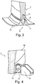
- the pivoting bearing means comprise a first bearing block 13, attached in the edge region of the exterior shell 5b of the pressure bulkhead 3 and radially projecting from the aforesaid, which first bearing block 13 by way of a bearing pin 14 interacts with a correspondingly formed second bearing block 15. While the first bearing block 13 is riveted to the pressure bulkhead 3, the second bearing block 15 is attached to the fuselage structure.
Claims (9)
- Cloison de pressurisation d'un aéronef avec une coque de fuselage (2) et une cloison de pressurisation (3) disposée à l'intérieur de celle-ci pour former une région de pressurisation interne au fuselage (a), laquelle cloison de pressurisation (3) est fixée sur le bord à l'intérieur de la coque de fuselage (2), dans laquelle la cloison de pressurisation (3) présente une structure en sandwich comprenant une âme de mousse (6) intercalée entre deux coques extérieures opposées (5a, 5b), la cloison de pressurisation (3) présente une section transversale lenticulaire, caractérisée en ce que l'âme de mousse (6) de la cloison de pressurisation (3) comprend un matériau de polyméthacrylimide.
- Cloison de pressurisation selon la revendication 1, caractérisée en ce que chaque coque extérieure (5a, 5b) comprend une section transversale incurvée formée selon une fonction parabolique.
- Cloison de pressurisation selon la revendication 1, caractérisée en ce que les coques extérieures (5a, 5b) de la cloison de pressurisation (3) comprennent un matériau plastique renforcé par des fibres.
- Cloison de pressurisation selon la revendication 1, caractérisée en ce que la cloison de pressurisation (3) est fixée, par l'intermédiaire de moyens de palier pivotants, dans l'intérieur à la coque de fuselage.
- Cloison de pressurisation selon la revendication 4, caractérisée en ce que les moyens de paliers pivotants sont réalisés sous la forme d'au moins une paire d'éléments d'articulation opposés (7a, 7b) qui sont fixés d'une part au bord de la coque extérieure respectivement associée (5a, 5b) de la cloison de pressurisation (3) et d'autre part à la structure de fuselage (2).
- Cloison de pressurisation selon la revendication 5, caractérisée en ce que l'élément d'articulation (7a, 7b) est fixé par un rivetage multi-lignes à la cloison de pressurisation (3) et à la structure de fuselage (2).
- Cloison de pressurisation selon la revendication 4, caractérisée en ce que les moyens de paliers pivotants comportent une bague de broche de palier (8) qui s'étend dans la direction radiale en s'éloignant du bord de la cloison de pressurisation (3), laquelle bague de broche de palier (8) interagit d'une manière verrouillée par enclenchement avec une bague de siège de palier (9) fixée à la structure de fuselage (2).
- Cloison de pressurisation selon la revendication 7, caractérisée en ce que la bague de siège de palier (9) comprend deux demi-bagues (10, 11) qui entourent partiellement la bague de broche de palier (8).
- Cloison de pressurisation selon la revendication 4, caractérisée en ce que les moyens de paliers pivotants comprennent au moins un premier bloc de palier (13), qui est fixé dans la région de bord d'une coque extérieure (5b) de la cloison de pressurisation (3) de manière à faire saillie radialement à partir de ladite coque extérieure, lequel premier bloc de palier (13) coopère, par l'intermédiaire d'une broche de palier (14), avec un second bloc de palier (15), conçu pour correspondre avec celui-ci, lequel second bloc de palier (15) est fixé à la structure de fuselage (2).
Applications Claiming Priority (3)
| Application Number | Priority Date | Filing Date | Title |
|---|---|---|---|
| US201261613061P | 2012-03-20 | 2012-03-20 | |
| DE102012005451A DE102012005451A1 (de) | 2012-03-20 | 2012-03-20 | Druckrumpf eines Luftfahrzeuges, mit einer Rumpfschale und einem hierin angeordneten Druckschott |
| PCT/EP2013/055501 WO2013139716A1 (fr) | 2012-03-20 | 2013-03-18 | Fuselage pressurisé d'avion avec coque de fuselage et cloison de pressurisation agencées en son sein |
Publications (2)
| Publication Number | Publication Date |
|---|---|
| EP2828146A1 EP2828146A1 (fr) | 2015-01-28 |
| EP2828146B1 true EP2828146B1 (fr) | 2017-05-03 |
Family
ID=49111848
Family Applications (1)
| Application Number | Title | Priority Date | Filing Date |
|---|---|---|---|
| EP13711334.6A Active EP2828146B1 (fr) | 2012-03-20 | 2013-03-18 | Fuselage pressurisé d'avion avec coque de fuselage et cloison de pressurisation agencées en son sein |
Country Status (4)
| Country | Link |
|---|---|
| US (1) | US9834298B2 (fr) |
| EP (1) | EP2828146B1 (fr) |
| DE (1) | DE102012005451A1 (fr) |
| WO (1) | WO2013139716A1 (fr) |
Families Citing this family (10)
| Publication number | Priority date | Publication date | Assignee | Title |
|---|---|---|---|---|
| DE102013114391A1 (de) | 2013-12-18 | 2015-06-18 | Airbus Operations Gmbh | Druckrumpf eines Flugzeuges, umfassend ein bewegbar relativ zur Rumpfstruktur befestigtes Druckschott |
| DE102014107404A1 (de) * | 2014-05-26 | 2015-11-26 | Airbus Operations Gmbh | Druckschott für einen Flugzeugrumpf |
| EP3095689B1 (fr) | 2015-05-20 | 2017-10-04 | Airbus Operations GmbH | Cloison de pressurisation pour un fuselage d'aéronef |
| EP3095688B1 (fr) | 2015-05-20 | 2017-10-04 | Airbus Operations GmbH | Cloison de pressurisation pour un fuselage d'aéronef |
| DE102015110194B4 (de) | 2015-06-24 | 2017-08-03 | Airbus Operations Gmbh | Druckschott für einen Flugzeugrumpf |
| KR102373719B1 (ko) * | 2015-06-29 | 2022-03-14 | 삼성전자 주식회사 | 복수의 구역들 중 일 구역의 기기를 제어하는 방법 및 이를 위한 장치 |
| DE102015111160B4 (de) * | 2015-07-09 | 2018-09-06 | Airbus Operations Gmbh | Rumpfstruktur und Verfahren zum Herstellen einer Rumpfstruktur |
| DE102015111935A1 (de) | 2015-07-22 | 2017-01-26 | Airbus Operations Gmbh | Druckschott für einen Flugzeugrumpf |
| USD837348S1 (en) | 2016-05-18 | 2019-01-01 | Bombardier Inc. | Aircraft lavatory cabinet |
| DE102018115541B4 (de) | 2018-06-27 | 2021-02-25 | Airbus Operations Gmbh | Druckschott für einen druckbeaufschlagten Rumpf eines Fahrzeugs |
Family Cites Families (12)
| Publication number | Priority date | Publication date | Assignee | Title |
|---|---|---|---|---|
| GB478307A (en) * | 1936-07-13 | 1938-01-13 | Martin James | Improvements in and relating to fuselage, body parts or hulls of aircraft |
| DE3534719A1 (de) | 1985-09-28 | 1987-04-02 | Messerschmitt Boelkow Blohm | Druckwand fuer einen unter inneren ueberdruck setzbaren rumpf eines luftfahrzeuges |
| JP2942218B2 (ja) * | 1997-06-30 | 1999-08-30 | 川崎重工業株式会社 | 高速先頭車両の連結器カバー |
| AT405813B (de) * | 1997-11-10 | 1999-11-25 | Fischer Adv Components Gmbh | Druckspant, insbesondere für flugzeuge |
| US6276866B1 (en) * | 1998-09-22 | 2001-08-21 | Elbert Rutan | Tensioned structural composite joint |
| DE102006029231B4 (de) | 2006-06-26 | 2013-09-26 | Airbus Operations Gmbh | Druckschott für einen Rumpf für die Luft- und Raumfahrt |
| US20080179459A1 (en) * | 2007-01-30 | 2008-07-31 | Airbus Espana, S.L. | Pressure bulkhead made of composite material for an aircraft |
| DE102007044388B4 (de) * | 2007-09-18 | 2012-08-02 | Airbus Operations Gmbh | Druckschott und Verfahren zum Unterteilen eines Luft- oder Raumfahrzeugs |
| DE102007052140B4 (de) * | 2007-10-31 | 2012-10-25 | Airbus Operations Gmbh | Struktur, insbesondere Rumpfstruktur eines Luft- oder Raumfahrzeugs |
| ES2343047B1 (es) * | 2007-12-13 | 2011-06-14 | Airbus España, S.L. | Fuselaje de aeronave atenuado acusticamente. |
| US20100155533A1 (en) * | 2008-12-23 | 2010-06-24 | Spirit Aerosystems, Inc. | Composite forward pressure bulkhead |
| US7988488B2 (en) | 2009-05-07 | 2011-08-02 | Lockheed Martin Corporation | Barrel nut connector assembly |
-
2012
- 2012-03-20 DE DE102012005451A patent/DE102012005451A1/de not_active Withdrawn
-
2013
- 2013-03-18 EP EP13711334.6A patent/EP2828146B1/fr active Active
- 2013-03-18 WO PCT/EP2013/055501 patent/WO2013139716A1/fr active Application Filing
-
2014
- 2014-09-19 US US14/491,251 patent/US9834298B2/en active Active
Also Published As
| Publication number | Publication date |
|---|---|
| DE102012005451A1 (de) | 2013-09-26 |
| EP2828146A1 (fr) | 2015-01-28 |
| US20150008285A1 (en) | 2015-01-08 |
| WO2013139716A1 (fr) | 2013-09-26 |
| US9834298B2 (en) | 2017-12-05 |
Similar Documents
| Publication | Publication Date | Title |
|---|---|---|
| EP2828146B1 (fr) | Fuselage pressurisé d'avion avec coque de fuselage et cloison de pressurisation agencées en son sein | |
| CN101801783B (zh) | 用于细分飞机或航天器的耐压舱壁和方法 | |
| EP2428444B1 (fr) | Cloison de pressurisation pour fuselage aérospatial | |
| US9902483B2 (en) | Window panel for an airframe and method of producing same | |
| US8146863B2 (en) | Aircraft doorway | |
| JP6171208B2 (ja) | ヘリコプタ | |
| CN102131698B (zh) | 用于支撑飞机的机身隔间结构中的部件的杆 | |
| US20080179459A1 (en) | Pressure bulkhead made of composite material for an aircraft | |
| JP6345505B2 (ja) | 圧力パネル | |
| US20080283662A1 (en) | Aircraft Interior Module | |
| CA2763113C (fr) | Composant de structure et procede de fabrication pour un composant de structure | |
| US20130112811A1 (en) | Aircraft with an integrated energy-absorbing deformation structure and aircraft with such a fuselage | |
| JP2009539690A (ja) | 航空機又は宇宙船の尾部構造体 | |
| JP7281313B2 (ja) | エネルギーを吸収する複合パネル | |
| US10501163B2 (en) | Pressure bulkhead for an aircraft fuselage, and an aircraft comprising such a pressure bulkhead | |
| EP2700573B1 (fr) | Fuselage d'avion sous pression comprenant une cloison de pressurisation | |
| CN101977811A (zh) | 用于飞机的机身结构 | |
| CA2649339A1 (fr) | Structure de fuselage et procede de fabrication d'une structure de fuselage | |
| EP3760534B1 (fr) | Vaisseau présurisé doté d'un panneau sensiblement plat | |
| CN207045685U (zh) | 一种轻量化翼型结构 | |
| CN106428514A (zh) | 用于飞机机身的耐压舱壁 | |
| PL231832B1 (pl) | Kadłub statku powietrznego i sposób wytwarzania kadłuba statku powietrznego | |
| KR20140087523A (ko) | 충돌에너지 흡수구조를 갖는 항공기 구조 |
Legal Events
| Date | Code | Title | Description |
|---|---|---|---|
| PUAI | Public reference made under article 153(3) epc to a published international application that has entered the european phase |
Free format text: ORIGINAL CODE: 0009012 |
|
| 17P | Request for examination filed |
Effective date: 20140717 |
|
| AK | Designated contracting states |
Kind code of ref document: A1 Designated state(s): AL AT BE BG CH CY CZ DE DK EE ES FI FR GB GR HR HU IE IS IT LI LT LU LV MC MK MT NL NO PL PT RO RS SE SI SK SM TR |
|
| AX | Request for extension of the european patent |
Extension state: BA ME |
|
| RIN1 | Information on inventor provided before grant (corrected) |
Inventor name: JESSRANG, MATHIAS Inventor name: GRASE, KARIM Inventor name: ROWEDDER, CARSTEN Inventor name: MUELLER, MARKUS Inventor name: DE JONG, CLAAS Inventor name: ZUARDY, ICHWAN |
|
| DAX | Request for extension of the european patent (deleted) | ||
| GRAP | Despatch of communication of intention to grant a patent |
Free format text: ORIGINAL CODE: EPIDOSNIGR1 |
|
| INTG | Intention to grant announced |
Effective date: 20161019 |
|
| RIN1 | Information on inventor provided before grant (corrected) |
Inventor name: GRASE, KARIM Inventor name: DE JONG, CLAAS Inventor name: ZUARDY, ICHWAN Inventor name: JESSRANG, MATHIAS Inventor name: MUELLER, MARKUS Inventor name: ROWEDDER, CARSTEN |
|
| STAA | Information on the status of an ep patent application or granted ep patent |
Free format text: STATUS: GRANT OF PATENT IS INTENDED |
|
| GRAS | Grant fee paid |
Free format text: ORIGINAL CODE: EPIDOSNIGR3 |
|
| GRAA | (expected) grant |
Free format text: ORIGINAL CODE: 0009210 |
|
| STAA | Information on the status of an ep patent application or granted ep patent |
Free format text: STATUS: THE PATENT HAS BEEN GRANTED |
|
| AK | Designated contracting states |
Kind code of ref document: B1 Designated state(s): AL AT BE BG CH CY CZ DE DK EE ES FI FR GB GR HR HU IE IS IT LI LT LU LV MC MK MT NL NO PL PT RO RS SE SI SK SM TR |
|
| REG | Reference to a national code |
Ref country code: GB Ref legal event code: FG4D |
|
| REG | Reference to a national code |
Ref country code: AT Ref legal event code: REF Ref document number: 889659 Country of ref document: AT Kind code of ref document: T Effective date: 20170515 Ref country code: CH Ref legal event code: EP |
|
| REG | Reference to a national code |
Ref country code: IE Ref legal event code: FG4D |
|
| REG | Reference to a national code |
Ref country code: DE Ref legal event code: R096 Ref document number: 602013020578 Country of ref document: DE |
|
| REG | Reference to a national code |
Ref country code: NL Ref legal event code: MP Effective date: 20170503 |
|
| REG | Reference to a national code |
Ref country code: AT Ref legal event code: MK05 Ref document number: 889659 Country of ref document: AT Kind code of ref document: T Effective date: 20170503 |
|
| REG | Reference to a national code |
Ref country code: LT Ref legal event code: MG4D |
|
| PG25 | Lapsed in a contracting state [announced via postgrant information from national office to epo] |
Ref country code: LT Free format text: LAPSE BECAUSE OF FAILURE TO SUBMIT A TRANSLATION OF THE DESCRIPTION OR TO PAY THE FEE WITHIN THE PRESCRIBED TIME-LIMIT Effective date: 20170503 Ref country code: FI Free format text: LAPSE BECAUSE OF FAILURE TO SUBMIT A TRANSLATION OF THE DESCRIPTION OR TO PAY THE FEE WITHIN THE PRESCRIBED TIME-LIMIT Effective date: 20170503 Ref country code: ES Free format text: LAPSE BECAUSE OF FAILURE TO SUBMIT A TRANSLATION OF THE DESCRIPTION OR TO PAY THE FEE WITHIN THE PRESCRIBED TIME-LIMIT Effective date: 20170503 Ref country code: NO Free format text: LAPSE BECAUSE OF FAILURE TO SUBMIT A TRANSLATION OF THE DESCRIPTION OR TO PAY THE FEE WITHIN THE PRESCRIBED TIME-LIMIT Effective date: 20170803 Ref country code: GR Free format text: LAPSE BECAUSE OF FAILURE TO SUBMIT A TRANSLATION OF THE DESCRIPTION OR TO PAY THE FEE WITHIN THE PRESCRIBED TIME-LIMIT Effective date: 20170804 Ref country code: AT Free format text: LAPSE BECAUSE OF FAILURE TO SUBMIT A TRANSLATION OF THE DESCRIPTION OR TO PAY THE FEE WITHIN THE PRESCRIBED TIME-LIMIT Effective date: 20170503 Ref country code: HR Free format text: LAPSE BECAUSE OF FAILURE TO SUBMIT A TRANSLATION OF THE DESCRIPTION OR TO PAY THE FEE WITHIN THE PRESCRIBED TIME-LIMIT Effective date: 20170503 |
|
| PG25 | Lapsed in a contracting state [announced via postgrant information from national office to epo] |
Ref country code: LV Free format text: LAPSE BECAUSE OF FAILURE TO SUBMIT A TRANSLATION OF THE DESCRIPTION OR TO PAY THE FEE WITHIN THE PRESCRIBED TIME-LIMIT Effective date: 20170503 Ref country code: NL Free format text: LAPSE BECAUSE OF FAILURE TO SUBMIT A TRANSLATION OF THE DESCRIPTION OR TO PAY THE FEE WITHIN THE PRESCRIBED TIME-LIMIT Effective date: 20170503 Ref country code: SE Free format text: LAPSE BECAUSE OF FAILURE TO SUBMIT A TRANSLATION OF THE DESCRIPTION OR TO PAY THE FEE WITHIN THE PRESCRIBED TIME-LIMIT Effective date: 20170503 Ref country code: BG Free format text: LAPSE BECAUSE OF FAILURE TO SUBMIT A TRANSLATION OF THE DESCRIPTION OR TO PAY THE FEE WITHIN THE PRESCRIBED TIME-LIMIT Effective date: 20170803 Ref country code: IS Free format text: LAPSE BECAUSE OF FAILURE TO SUBMIT A TRANSLATION OF THE DESCRIPTION OR TO PAY THE FEE WITHIN THE PRESCRIBED TIME-LIMIT Effective date: 20170903 Ref country code: RS Free format text: LAPSE BECAUSE OF FAILURE TO SUBMIT A TRANSLATION OF THE DESCRIPTION OR TO PAY THE FEE WITHIN THE PRESCRIBED TIME-LIMIT Effective date: 20170503 Ref country code: PL Free format text: LAPSE BECAUSE OF FAILURE TO SUBMIT A TRANSLATION OF THE DESCRIPTION OR TO PAY THE FEE WITHIN THE PRESCRIBED TIME-LIMIT Effective date: 20170503 |
|
| PG25 | Lapsed in a contracting state [announced via postgrant information from national office to epo] |
Ref country code: SK Free format text: LAPSE BECAUSE OF FAILURE TO SUBMIT A TRANSLATION OF THE DESCRIPTION OR TO PAY THE FEE WITHIN THE PRESCRIBED TIME-LIMIT Effective date: 20170503 Ref country code: DK Free format text: LAPSE BECAUSE OF FAILURE TO SUBMIT A TRANSLATION OF THE DESCRIPTION OR TO PAY THE FEE WITHIN THE PRESCRIBED TIME-LIMIT Effective date: 20170503 Ref country code: EE Free format text: LAPSE BECAUSE OF FAILURE TO SUBMIT A TRANSLATION OF THE DESCRIPTION OR TO PAY THE FEE WITHIN THE PRESCRIBED TIME-LIMIT Effective date: 20170503 Ref country code: RO Free format text: LAPSE BECAUSE OF FAILURE TO SUBMIT A TRANSLATION OF THE DESCRIPTION OR TO PAY THE FEE WITHIN THE PRESCRIBED TIME-LIMIT Effective date: 20170503 Ref country code: CZ Free format text: LAPSE BECAUSE OF FAILURE TO SUBMIT A TRANSLATION OF THE DESCRIPTION OR TO PAY THE FEE WITHIN THE PRESCRIBED TIME-LIMIT Effective date: 20170503 |
|
| REG | Reference to a national code |
Ref country code: DE Ref legal event code: R097 Ref document number: 602013020578 Country of ref document: DE |
|
| PG25 | Lapsed in a contracting state [announced via postgrant information from national office to epo] |
Ref country code: SM Free format text: LAPSE BECAUSE OF FAILURE TO SUBMIT A TRANSLATION OF THE DESCRIPTION OR TO PAY THE FEE WITHIN THE PRESCRIBED TIME-LIMIT Effective date: 20170503 Ref country code: IT Free format text: LAPSE BECAUSE OF FAILURE TO SUBMIT A TRANSLATION OF THE DESCRIPTION OR TO PAY THE FEE WITHIN THE PRESCRIBED TIME-LIMIT Effective date: 20170503 |
|
| PLBE | No opposition filed within time limit |
Free format text: ORIGINAL CODE: 0009261 |
|
| STAA | Information on the status of an ep patent application or granted ep patent |
Free format text: STATUS: NO OPPOSITION FILED WITHIN TIME LIMIT |
|
| REG | Reference to a national code |
Ref country code: FR Ref legal event code: PLFP Year of fee payment: 6 |
|
| 26N | No opposition filed |
Effective date: 20180206 |
|
| PG25 | Lapsed in a contracting state [announced via postgrant information from national office to epo] |
Ref country code: SI Free format text: LAPSE BECAUSE OF FAILURE TO SUBMIT A TRANSLATION OF THE DESCRIPTION OR TO PAY THE FEE WITHIN THE PRESCRIBED TIME-LIMIT Effective date: 20170503 |
|
| REG | Reference to a national code |
Ref country code: CH Ref legal event code: PL |
|
| PG25 | Lapsed in a contracting state [announced via postgrant information from national office to epo] |
Ref country code: MC Free format text: LAPSE BECAUSE OF FAILURE TO SUBMIT A TRANSLATION OF THE DESCRIPTION OR TO PAY THE FEE WITHIN THE PRESCRIBED TIME-LIMIT Effective date: 20170503 |
|
| REG | Reference to a national code |
Ref country code: BE Ref legal event code: MM Effective date: 20180331 |
|
| REG | Reference to a national code |
Ref country code: IE Ref legal event code: MM4A |
|
| PG25 | Lapsed in a contracting state [announced via postgrant information from national office to epo] |
Ref country code: LU Free format text: LAPSE BECAUSE OF NON-PAYMENT OF DUE FEES Effective date: 20180318 |
|
| PG25 | Lapsed in a contracting state [announced via postgrant information from national office to epo] |
Ref country code: IE Free format text: LAPSE BECAUSE OF NON-PAYMENT OF DUE FEES Effective date: 20180318 |
|
| PG25 | Lapsed in a contracting state [announced via postgrant information from national office to epo] |
Ref country code: BE Free format text: LAPSE BECAUSE OF NON-PAYMENT OF DUE FEES Effective date: 20180331 Ref country code: CH Free format text: LAPSE BECAUSE OF NON-PAYMENT OF DUE FEES Effective date: 20180331 Ref country code: LI Free format text: LAPSE BECAUSE OF NON-PAYMENT OF DUE FEES Effective date: 20180331 |
|
| PG25 | Lapsed in a contracting state [announced via postgrant information from national office to epo] |
Ref country code: MT Free format text: LAPSE BECAUSE OF NON-PAYMENT OF DUE FEES Effective date: 20180318 |
|
| PG25 | Lapsed in a contracting state [announced via postgrant information from national office to epo] |
Ref country code: TR Free format text: LAPSE BECAUSE OF FAILURE TO SUBMIT A TRANSLATION OF THE DESCRIPTION OR TO PAY THE FEE WITHIN THE PRESCRIBED TIME-LIMIT Effective date: 20170503 |
|
| PG25 | Lapsed in a contracting state [announced via postgrant information from national office to epo] |
Ref country code: HU Free format text: LAPSE BECAUSE OF FAILURE TO SUBMIT A TRANSLATION OF THE DESCRIPTION OR TO PAY THE FEE WITHIN THE PRESCRIBED TIME-LIMIT; INVALID AB INITIO Effective date: 20130318 Ref country code: PT Free format text: LAPSE BECAUSE OF FAILURE TO SUBMIT A TRANSLATION OF THE DESCRIPTION OR TO PAY THE FEE WITHIN THE PRESCRIBED TIME-LIMIT Effective date: 20170503 |
|
| PG25 | Lapsed in a contracting state [announced via postgrant information from national office to epo] |
Ref country code: MK Free format text: LAPSE BECAUSE OF NON-PAYMENT OF DUE FEES Effective date: 20170503 Ref country code: CY Free format text: LAPSE BECAUSE OF FAILURE TO SUBMIT A TRANSLATION OF THE DESCRIPTION OR TO PAY THE FEE WITHIN THE PRESCRIBED TIME-LIMIT Effective date: 20170503 |
|
| PG25 | Lapsed in a contracting state [announced via postgrant information from national office to epo] |
Ref country code: AL Free format text: LAPSE BECAUSE OF FAILURE TO SUBMIT A TRANSLATION OF THE DESCRIPTION OR TO PAY THE FEE WITHIN THE PRESCRIBED TIME-LIMIT Effective date: 20170503 |
|
| PGFP | Annual fee paid to national office [announced via postgrant information from national office to epo] |
Ref country code: FR Payment date: 20230324 Year of fee payment: 11 |
|
| PGFP | Annual fee paid to national office [announced via postgrant information from national office to epo] |
Ref country code: GB Payment date: 20230322 Year of fee payment: 11 |
|
| PGFP | Annual fee paid to national office [announced via postgrant information from national office to epo] |
Ref country code: DE Payment date: 20240320 Year of fee payment: 12 |