EP2827967B2 - Elément de filtrage d'un filtre pour le filtrage de fluides et filtre - Google Patents
Elément de filtrage d'un filtre pour le filtrage de fluides et filtre Download PDFInfo
- Publication number
- EP2827967B2 EP2827967B2 EP13701749.7A EP13701749A EP2827967B2 EP 2827967 B2 EP2827967 B2 EP 2827967B2 EP 13701749 A EP13701749 A EP 13701749A EP 2827967 B2 EP2827967 B2 EP 2827967B2
- Authority
- EP
- European Patent Office
- Prior art keywords
- support section
- fold
- filter
- filter medium
- section
- Prior art date
- Legal status (The legal status is an assumption and is not a legal conclusion. Google has not performed a legal analysis and makes no representation as to the accuracy of the status listed.)
- Active
Links
- 239000012530 fluid Substances 0.000 title claims description 62
- 238000001914 filtration Methods 0.000 title claims description 6
- 230000001070 adhesive effect Effects 0.000 claims description 43
- 239000000853 adhesive Substances 0.000 claims description 42
- 239000004831 Hot glue Substances 0.000 claims description 15
- 239000007789 gas Substances 0.000 claims description 8
- 238000002485 combustion reaction Methods 0.000 claims description 7
- 239000004952 Polyamide Substances 0.000 claims description 3
- 230000007423 decrease Effects 0.000 claims description 3
- 239000005038 ethylene vinyl acetate Substances 0.000 claims description 3
- 229920002647 polyamide Polymers 0.000 claims description 3
- 229920000098 polyolefin Polymers 0.000 claims description 3
- 239000000463 material Substances 0.000 description 14
- 239000003292 glue Substances 0.000 description 9
- 239000011324 bead Substances 0.000 description 8
- 206010040954 Skin wrinkling Diseases 0.000 description 5
- 238000004519 manufacturing process Methods 0.000 description 5
- 239000004033 plastic Substances 0.000 description 4
- 229920003023 plastic Polymers 0.000 description 4
- 241000237942 Conidae Species 0.000 description 2
- 238000004026 adhesive bonding Methods 0.000 description 2
- 238000005187 foaming Methods 0.000 description 2
- 239000010410 layer Substances 0.000 description 2
- 230000005540 biological transmission Effects 0.000 description 1
- 238000009826 distribution Methods 0.000 description 1
- 238000005516 engineering process Methods 0.000 description 1
- 238000002474 experimental method Methods 0.000 description 1
- 239000000446 fuel Substances 0.000 description 1
- 230000012447 hatching Effects 0.000 description 1
- 239000007788 liquid Substances 0.000 description 1
- 238000012986 modification Methods 0.000 description 1
- 230000004048 modification Effects 0.000 description 1
- 239000003921 oil Substances 0.000 description 1
- 230000035515 penetration Effects 0.000 description 1
- 230000002093 peripheral effect Effects 0.000 description 1
- 229920000728 polyester Polymers 0.000 description 1
- 239000011148 porous material Substances 0.000 description 1
- 230000008092 positive effect Effects 0.000 description 1
- 238000003825 pressing Methods 0.000 description 1
- 238000012545 processing Methods 0.000 description 1
- 238000007789 sealing Methods 0.000 description 1
- 230000009974 thixotropic effect Effects 0.000 description 1
- XLYOFNOQVPJJNP-UHFFFAOYSA-N water Substances O XLYOFNOQVPJJNP-UHFFFAOYSA-N 0.000 description 1
- 230000037303 wrinkles Effects 0.000 description 1
Images


Classifications
-
- B—PERFORMING OPERATIONS; TRANSPORTING
- B01—PHYSICAL OR CHEMICAL PROCESSES OR APPARATUS IN GENERAL
- B01D—SEPARATION
- B01D46/00—Filters or filtering processes specially modified for separating dispersed particles from gases or vapours
- B01D46/52—Particle separators, e.g. dust precipitators, using filters embodying folded corrugated or wound sheet material
- B01D46/521—Particle separators, e.g. dust precipitators, using filters embodying folded corrugated or wound sheet material using folded, pleated material
- B01D46/523—Particle separators, e.g. dust precipitators, using filters embodying folded corrugated or wound sheet material using folded, pleated material with means for maintaining spacing between the pleats or folds
-
- B—PERFORMING OPERATIONS; TRANSPORTING
- B01—PHYSICAL OR CHEMICAL PROCESSES OR APPARATUS IN GENERAL
- B01D—SEPARATION
- B01D46/00—Filters or filtering processes specially modified for separating dispersed particles from gases or vapours
- B01D46/52—Particle separators, e.g. dust precipitators, using filters embodying folded corrugated or wound sheet material
- B01D46/521—Particle separators, e.g. dust precipitators, using filters embodying folded corrugated or wound sheet material using folded, pleated material
-
- B—PERFORMING OPERATIONS; TRANSPORTING
- B01—PHYSICAL OR CHEMICAL PROCESSES OR APPARATUS IN GENERAL
- B01D—SEPARATION
- B01D2201/00—Details relating to filtering apparatus
- B01D2201/12—Pleated filters
- B01D2201/127—Pleated filters with means for keeping the spacing between the pleats
Definitions
- the invention relates to a filter element of a filter for filtering fluids, in particular gases, in particular intake air, in particular an internal combustion engine, in particular a motor vehicle, with a filter medium folded in a zigzag shape with an untreated fluid side and a clean fluid side, with on the untreated fluid side and/or on the clean fluid side of the filter medium, at least one elongate support section is arranged on a corresponding surface of the filter medium, which extends at least in sections obliquely or perpendicularly to fold edges of the filter medium, with a height extension of the at least one support section perpendicular to the surface of the filter medium along its longitudinal direction in the direction from a fold base to a Pleat tip of a fold of the filter medium increases, so that the at least one support section in the folded filter medium each corresponds to its free side facing away from the surface of the filter medium on a the free side of an opposite support section in a fold interspace or on the surface of an opposite medium section in the fold interspace.
- the invention relates to a filter for filtering fluids, in particular gases, in particular intake air, in particular an internal combustion engine, in particular a motor vehicle, with a filter element, in particular a filter element according to the invention, with a filter medium folded in a zigzag shape with a raw fluid side and a clean fluid side, wherein on on the raw fluid side and/or on the clean fluid side of the filter medium, at least one elongated support section is arranged on a corresponding surface of the filter medium, which at least in sections runs obliquely or perpendicularly to the fold edges of the filter medium, with a height extension of the at least one support section perpendicular to the surface of the filter medium along its Longitudinally in the direction of a fold base to a fold tip of a fold of the filter medium increases, so that the at least one support section in the folded filter medium each with its surface e of the filter medium facing away from a corresponding free side of an opposite support section in a fold interspace or on the surface of an
- WO 2002/055179 A1 U.S. 7,661,540 B2 , DE 43 45 121 A1 and EP 1059108 A1 designs of filter elements with spacing means for folds are known.
- a filter for filtering fluids with a filter element with a filter medium folded in a zigzag shape with a raw side and a clean side is known.
- a plurality of elongated sections of adhesive are arranged along at least two traces of adhesive on the filter medium, which run at least in sections obliquely or perpendicularly to fold edges. At least one adhesive section and at least one adhesive interruption are arranged on each adhesive line.
- the expansion of the adhesive sections perpendicular to the filter medium along the adhesive track varies, so that the free side of the adhesive sections in the folded filter medium facing away from the filter medium rests flat against a corresponding free side of an opposite adhesive section in a fold gap or on the surface of a fold gap opposite medium section.
- the invention is based on the object of designing a filter element and a filter of the type mentioned at the outset, in which the at least one support section can be realized with the lowest possible manufacturing outlay and material outlay.
- the at least one support section should be realized in as space-saving a manner as possible.
- a ratio of the effective filter area to the total area of the filter medium should be as large as possible.
- a width extension of the at least one support section decreases parallel to the surface of the filter medium and perpendicular to its length extension in the direction from the fold tip to the fold bottom of the fold of the filter medium.
- the at least one support section has a cross section that tapers overall when viewed from the fold tip.
- the height extent is the height of the corresponding cross section of the support section in this cross-sectional plane.
- a linear dimension is the maximum length of the support section.
- the extent of the width at the widest point can advantageously be between about 1 mm and about 3 mm, preferably about 2 mm.
- the height dimension at the highest point can advantageously be between about 0.8 mm and about 2 mm, preferably about 1.2 mm.
- the extent of the width can be between about 0.3 mm and 0.6 mm, preferably about 0.45 mm.
- the height dimension at the lowest point can be between about 0.6 mm and 0.9 mm, preferably about 0.75 mm. Due to the tapering of the support section toward the bottom of the fold, any internal mechanical stresses that can lead to the space between the folds being pressed apart at the bottom of the fold can be reduced. In this way, the shape of the gaps between the folds can be optimized.
- the at least one support section is made of an adhesive
- the at least one support section can have a cross section similar to a segment of a circular or elliptical surface, at least on its side facing away from the filter medium.
- the at least one support section can therefore have the overall shape of a cone or a truncated cone with an approximately circular or elliptical base.
- the base area and thus the cone shell or truncated cone shell can be flattened on the side facing the filter medium and/or the side facing the opposite support section or the surface of the medium section opposite in the interfold space.
- the support section can be applied to the filter medium in a simple manner, in particular by means of a nozzle.
- a circular or elliptical cross section can easily be realized.
- a ratio of the height extent of the at least one support section to the width extent can be approximately constant over the length extent.
- the ratio of the height extension to the width extension can be easily specified, in particular by specifying the material from which the support section is formed, a geometry of a tool for applying the material, in particular a nozzle geometry, an application speed at which the material of the support section is applied to the filter medium, the material and the properties of the filter medium and/or a dosing head of a nozzle can be influenced.
- a uniform support section can be realized with a constant ratio of height expansion to width expansion.
- a uniform support function can be realized with the uniform support section.
- a uniform support section can lead to a uniform flow of the fluid in the fold spaces.
- the ratio of the height dimension to the width dimension can be between about 1/5 and about 5/5, preferably greater than about 3/5.
- the at least one support section can extend over at least one folded edge.
- the at least one support section can extend over a fold edge of a fold tip.
- the folds can be further stabilized by the at least one support section.
- the application of the at least one support section can be simplified in this way.
- a material feed does not have to be interrupted in the area of the folded edge.
- the ratio of height expansion to width expansion can be lower than in the remaining area of the fold.
- excess material for the support section can be prevented from causing the fold gap to widen there. In the area of a fold tip, it can thus be prevented that the at least one support section protrudes too far beyond the fold medium outside the bellows.
- the at least one support section in a fold bottom can advantageously not extend over a fold edge there. In this way it can be avoided that the at least one support section presses apart the opposite medium sections in a fold gap in the area of the fold base.
- the at least one support section can advantageously end at a distance of at least 1 mm, preferably more than 1.5 mm, from the fold edge in the bottom of the fold. In this way it can be prevented that any excess material for realizing the support section leads to a bulging or widening of the space between the folds. This could negatively affect the optimal shape of the fold.
- the folds of the filter medium can be approximately V-shaped.
- V-shaped folds a pressure gradient between the raw fluid side and the clean fluid side can be reduced during operation of the filter element.
- an optimal loading capacity of the filter element can be achieved with V-shaped folds.
- sides of the at least one support section and of the opposite support section or of the opposite medium section that abut one another are glued to one another in the space between the folds.
- An optimal connection of the second can be realized by gluing.
- tight connections can also be realized with an adhesive bond. Bonding can be easily implemented.
- the support section can be made of a material which is still adhesive when the folds are raised and thereby produces an adhesive effect. After setting up, the material can dry and harden and stabilize the bond.
- a separate adhesive may be applied to the at least one support portion and/or the opposing support portion and/or the opposing media portion prior to the erection of the folds.
- sides of the at least one support section and of the opposite support section or of the opposite medium section lying against one another in the fold interstice can have planar contact with one another in the direction of the width extension and in the direction of the length extension.
- a planar contact in the case of a planar contact the courses of the opposite surfaces in the direction of the width extension and in the direction of the length extension are clearly adapted to one another with the naked eye.
- An optimal connection can be created with a flat contact. In this way, the supporting forces, which are transmitted with the support section, can be transmitted evenly.
- the at least one support section can have at least one interruption in the longitudinal direction.
- the fluid to be filtered can pass from one side of the support section to the other through the at least one interruption.
- Flow areas are realized in the interruptions, in which the fluid to be filtered can be directed essentially perpendicularly to the fold edges. In this way, flow areas can be uniformly charged with fluid. Compensating flows between adjacent flow areas, which are separated from one another by the at least one support section, can thus be made possible.
- the interruptions of support sections that are arranged next to one another on opposite sides of the filter medium or on one side of the filter medium can be offset from one another.
- segments of the support sections can be arranged on the raw fluid side and on the clean fluid side in such a way that at least one of the segments on the raw fluid side projects beyond at least one of the interruptions on the clean fluid side in the longitudinal direction on both sides and overlaps with its ends the segments of the support section on the clean fluid side, which adjoin the interruption, and/or at least one of the segments of the support section on the clean fluid side projects beyond at least one of the interruptions on the untreated fluid side on both sides and overlaps with its ends the segments of the support section on the untreated fluid side that adjoin the interruption.
- the stability of the folds can be increased overall by the mutually overlapping support section segments on the clean fluid side and on the raw fluid side. In this way, gaps in the support of the filter medium can be avoided.
- the overlapping of the support sections can improve a force transmission of the support sections on the clean fluid side to the corresponding support sections on the raw fluid side.
- the at least one support section can be made from a hot-melt adhesive, in particular based on polyamide, polyolefin, ethylene vinyl acetate (EVA).
- the at least one support section can be applied to the filter medium quickly and easily with adhesive.
- nozzle arrangements can be used for this purpose.
- a hot-melt adhesive can be easily heated during processing and thus softened. As it cools, the hot melt adhesive dries and hardens.
- a support section made of adhesive can also be referred to as a bead of glue.
- the at least one support section can advantageously be realized from a foamed adhesive.
- a foamed adhesive Preferably, at least 50% of the volume of the at least one support section can be formed by gas inclusions. The gas inclusions occur during foaming.
- the flexibility of the at least one support section can be improved by the foaming of the adhesive.
- the foamed adhesive may have an urge to expand. This can result in a tightness of the connection of the at least one support section to the surface of the opposite support section or improve the opposite media section.
- foamed adhesive can set faster than non-foamed adhesive. In this way, a production speed can be increased.
- a web speed can be increased, in particular when the adhesive is applied with a nozzle to a continuous filter medium web.
- Foamed adhesive can be pressed with less force when setting up the folds than non-foamed adhesive. A force exerted by excess adhesive on the folds can thus be reduced. This can have a positive effect on maintaining the desired wrinkle shape.
- penetration of porous or uneven surfaces of the filter medium can be improved with foamed adhesive.
- Foamed adhesive can penetrate deeper into surface pores than non-foamed adhesive. Filling properties of the adhesive can be improved in this way. Structural unevenness of the filter medium can be compensated with foamed adhesive.
- Foamed adhesive can also be applied to surfaces that are inclined or vertical to the horizontal. With foamed adhesive, thixotropic properties of the at least one support section can be improved. Overall, the production costs, in particular production times, and the material costs can be reduced through the use of foamed adhesive.
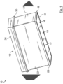
- a filter element 10 according to a first exemplary embodiment is shown.
- the filter element can be installed in a filter housing (not shown) of a filter for a fluid. Gaseous or liquid fluids can be filtered with the filter element 10 .
- a filter element 10 can be used in an air filter of an internal combustion engine of a motor vehicle.
- the filter element 10 has an inflow side 12 on the raw fluid side and an outflow side 14 on the clean fluid side.
- the filter element 10 comprises a filter bellows 17 made of a filter medium 16 folded in a zigzag shape several times figure 3 shown. Folds 18 of the filter medium 16 extend between the inflow side 12 and the outflow side 14. There is a fold tip 20 of a fold 18 on the inflow side 12 and the outflow side 14 its side facing the filter element 10 is provided with a layer of hot-melt adhesive. This hot melt adhesive layer is a flat Bonding of the polyester fleece to the filter element 10, with end faces 24 of the filter bellows 17 also being sealed.
- the filter element 10 comprises a main frame 26 and an auxiliary frame 28.
- the main frame 26 carries an axial seal 30, which seals in the direction of the outflow side 14 and is introduced in a groove of the main frame 26 or in a groove between the main frame 26 and side surfaces 22.
- the auxiliary frame 28 is connected to the side surfaces 22 by an adhesive connection and has radial surfaces 32 and axial surfaces 34 for supporting the filter element 10 in a filter housing, not shown.
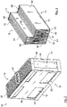
- FIG 2 shows another embodiment of a filter element 10, which to the first embodiment of the figure 1 is similar. Those elements that differ from those of the first embodiment figure 1 are similar are provided with the same reference numerals.
- a plastic frame 36 is applied by means of a hot-melt adhesive connection to the side faces 22 of the filter medium 16 that cannot be flowed through. On the end faces 24 , the end face 24 is also sealed by the hot-melt adhesive. On the end faces 38 , openings 39 are made in the plastic frame 36 .
- the plastic frame 36 carries an axial seal 40 on the inflow side 12, which can be brought into engagement with a corresponding sealing surface of a filter housing, not shown.
- a handle 42 is provided, which is connected to the plastic frame 36 and is used for better handling of the filter element 10 .
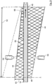
- FIG 4 a section of the stretched out filter medium 16 of the filter bellows 17 before folding is shown in a side view.
- Support sections 44 made of hot-melt adhesive are arranged on one side of the filter medium 16 .
- the hot-melt adhesive can be based on polyamide, polyolefin or ethylene vinyl acetate (EVA), for example.
- the support portions 44 have an elongated shape. They run perpendicular to embossed folds 46. The positions of the folds 46 are in FIG figure 4 indicated by dash-dotted lines.
- middle fold edge 16 is in the folded filter bellows 17 on the in the figure 4 shown lower side of the filter medium 16 a fold tip 20 realized.
- the fold tips 20 and the fold bases 48 are each arranged in reverse.
- the support sections 44 of a fold 18 are constructed essentially symmetrically.
- a respective height dimension 50 of the support sections 44 perpendicular to the surface of the filter medium 16 in the figure 4 is indicated by a double arrow, takes along the length of 52, in which figure 4 likewise indicated by a double arrow, in the direction from a fold base 48 to a fold tip 20 of a fold 18 of the filter medium 16 .
- the height extent 50 describes the extent of a cross-sectional area of the support section 44 at its highest point.
- a width extension of the support sections 44 parallel to the surface of the filter medium 16 and perpendicular to its longitudinal extension 52 decreases in the direction from the fold tip 20 to the fold base 48 of the fold 18 .
- cross sections of the support section 44 shown below are shown as examples in four sectional planes spaced apart from one another in the longitudinal direction of the support section 44 .
- the respective width extension 54 of the cross sections is indicated with double arrows.
- the width dimension 54 describes the width of the cross section of the support section 44 at its widest point.
- the support sections 44 have an elliptical course in cross section on their sides facing away from the filter medium 16 . On their sides facing the filter medium 16, the support sections 44 are flattened in cross section.
- a ratio of the height extent 50 of the cross sections of the support sections 44 to their width extent 54 is approximately constant over the longitudinal direction.
- the ratio of height dimension 50 to width dimension 54 is between about 1/5 and about 5/5. Preferably it is greater than about 3/5.
- the two support sections 44 of the subsequent folds between 62 are in the area of the figure 4 middle folding edge 46 connected to each other. Likewise, the support sections 44 with subsequent, in the figure 4 not shown, supporting portions of the adjacent pleat spaces 62 connected.
- the supporting edge sections 44 connected to one another can be referred to as a continuous supporting edge section, which extend over the folding edges 46 .
- FIG 6 is a detail of one of the support portions 44 of the filter medium 16 from the figures 4 and 5 shown in an oblique view.
- a cross section of an alternative support section 144 with a smaller ratio of the height dimension 50 to a width dimension 154 is indicated there with a dashed peripheral line and dashed hatching.
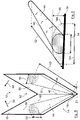
- FIG 5 is a section of the filter medium 16 from the figure 4 shown in a phase when the folds 18 are set up.
- the two medium sections 56 are folded towards one another along the folded edge 46, which is shown in FIG figure 5 is indicated by two arrows 58.
- the folds 18 are raised while the hot-melt adhesive of the support sections 44 is still soft and adhesive.
- the free sides 60 of the support sections 44 facing away from the filter medium 16 lie flat against one another in the space 62 between the folds. This is in the figure 7 shown.
- the folds 18 are each V-shaped. the opposite ones Sides 60 of the two support sections 44 are pressed against one another when the folds 18 are erected and thereby bond.
- the bonding between the sides 60 takes place in the longitudinal direction of the support sections 44 along a narrow surface. Depending on the width extension 54 and the contact pressure on the support sections 44, the area to be bonded is spread out accordingly. The support sections 44 can thereby be flattened.
- Both sides of the filter medium 16 shown are provided with corresponding support sections 44 .
- the support sections 44 lying against one another support one another and thus keep the folds 18 in the intended shape.
- the support portions 44 prevent the pleats 18 from collapsing.
- the support sections 44 can favorably influence the course of the flow of the fluid in the gaps between the folds 62 .
- the support sections 44 can, for example, also be arranged in the area of the fold edges 46 of the filter bellows 17 in such a way that they can seal off the filter bellows 17 and thus the fold spaces 62 from the outside.
- FIG figure 9 An example of an arrangement of the support sections 44 on opposite sides of the filter medium 16 is in FIG figure 9 shown.
- a nozzle arrangement with two nozzles 64 located opposite one another is also shown there, with which the hot-melt adhesive is sprayed onto the filter medium 16 in order to implement the support sections 44 .
- the sheet-like filter medium 16 in which figure 9 indicated by an arrow 66 drawn between the two nozzles 64 therethrough.
- figure 9 For better clarity is in the figure 9 only a section of the filter medium 16 between two adjacent folding edges 46 is shown, which is indicated by dot-dashed lines.
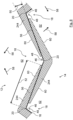
- FIG 8 a section of a further exemplary embodiment of a filter bellows 17 is shown, in which the folds 16 have not yet been completely erected during a production process.
- the support sections 244 end in the fold bases 48 at a distance from the fold edges 46 there. When the folds 18 are raised further, this prevents excess adhesive from pushing the folds 18 apart in the area of the fold bases 48, which is what can lead to a bulging of the gaps between the folds 62. This would destroy the V-shape of the folds 18.
- the support sections 244 extend beyond the fold edges 46 .
- FIG. 10 a section of a further exemplary embodiment of a filter bellows 17 is shown.
- Support sections 344 interrupted in each fold gap 62.
- the support sections 344 also end at a distance from the pleat tips 20.
- Interruptions 368 of the support sections 344 on the opposite sides of the filter medium 16, i.e. on the raw fluid side, the inflow side 12, and the clean fluid side, the outflow side 14, are arranged offset to one another. This ensures that both in the area of the fold tips 20 and in the vicinity of the fold bases 48 there is an overlap of the support sections 44 on the clean fluid side and on the raw fluid side.
- segments of the support sections that are separated by the interruptions 368 are arranged in such a way that one of the segments on the raw fluid side projects beyond one of the interruptions 368 on the clean fluid side on both sides in the direction of the longitudinal extent 52 and its ends connect with the segments of the Supporting section 344 overlaps on the clean fluid side, adjoining the interruption 368 there.
- One of the segments of a support section 344 on the clean fluid side protrudes beyond the interruption 368 on the untreated fluid side on both sides and its ends overlap with the segments of the support section 344 on the untreated fluid side, which adjoin the interruption 368 there.
- the invention is not limited to air filter elements for internal combustion engines in motor vehicles. Rather, it can also be used in other types of internal combustion engines, such as industrial engines. The invention can also be used outside of motor vehicle technology.
- the filter element 10 can also be used to filter other fluids, for example oil, fuel or water.
- the support sections 44; 144; 244; 344 can, at least on their side facing away from the filter medium 16, also have a different shape, for example a circular shape, instead of an elliptical shape.
- the support sections 44; 144; 244; 344 can with their free sides 60 facing away from the respective medium section 56 instead of on an opposite supporting section 44; 144; 244; 344 also rest against the surface of the opposite medium section 56 in the fold interstice 62 and be glued to it.
- a different type of adhesive can also be used to implement the support sections 44; 144; 244; 344 can be used.
- a different type of material in particular one that can be shaped for the purpose of application, can also be used to implement the support sections 44; 144; 244; 344 can be used.
- the hot-melt adhesive can also be foamed.
- the support sections 44; 144; 344, 244 can each consist of 50% hot-melt adhesive and 50% foamed-in gas. More than 50% foamed gas can also be provided.
- the ratio of height expansion 50 to width dimension 54 of the support sections 44; 144; 244; 344 in a cross-sectional plane can also vary in the direction of length extension 52 .
- the folds 18 of the filter bellows 17 can also have a different shape, for example a U-shape, instead of being V-shaped.
- the folds 18 can also be graded in the area of the fold bases 48 .
- a V-shape that progressively widens from the corresponding folded edge 46 can be provided in a region of the respective fold base 48 .
- the opposite medium sections 56, which delimit a fold gap 62 of the fold 18, can run parallel to one another.
- the interruptions 368 can also be arranged differently. More or fewer interruptions can also be provided.
- the support portions 344 can also extend over the respective pleat tips 20 .
- the fold bases 48 can also be free of support sections 344 .
Landscapes
- Chemical & Material Sciences (AREA)
- Chemical Kinetics & Catalysis (AREA)
- Filtering Of Dispersed Particles In Gases (AREA)
- Filtering Materials (AREA)
Claims (13)
- Élément filtrant (10) d'un filtre destiné au filtrage de fluides, en particulier de gaz, en particulier d'air d'aspiration, en particulier d'un moteur à combustion interne, en particulier d'un véhicule automobile, avec un milieu filtrant (16) plié en accordéon avec un côté de fluide brut (12) et un côté de fluide pur (14), au moins une section d'appui longitudinale (44 ; 144 ; 244 ; 344) étant prévue du côté de fluide brut (12) et/ou du côté de fluide pur (14) du milieu filtrant (16) sur une surface correspondante du milieu filtrant (16), la section d'appui (44 ; 144 ; 244 ; 344), au moins au nombre d'une, étant constituée d'une colle et s'étendant, au moins sur certaines sections, en travers ou verticalement par rapport à des bords de pliage (46) du milieu filtrant (16), une étendue en hauteur (50) de la section d'appui (44 ; 144 ; 244 ; 344), au moins au nombre d'une, augmentant verticalement par rapport à la surface du milieu filtrant (16), le long de son sens longitudinal (52), d'un fond de pli (48) vers une crête (20) d'un pli (18) du milieu filtrant (16), de sorte que la section d'appui (44 ; 144 ; 244 ; 344), au moins au nombre d'une, touche, lorsque le milieu filtrant (16) est plié, avec son côté libre (60) opposé à la surface du milieu filtrant (16), un côté libre correspondant (60) d'une section d'appui (44 ; 144 ; 244 ; 344) opposée située dans un interstice de pliage (62) ou une surface d'une section du milieu opposée située dans l'interstice de pliage, caractérisé en ce qu'une étendue en largeur (54) de la section d'appui (44 ; 144 ; 244 ; 344), au moins au nombre d'une et constituée de colle, diminue parallèlement par rapport à la surface du milieu filtrant (16) et verticalement par rapport à son sens longitudinal (52), de la crête de pli (20) vers le fond (48) du pli (18) du milieu filtrant (16), et en ce que, dans l'interstice de pliage (62), des côtés adjacents (60) de la section d'appui (44 ; 144 ; 244 ; 344), au moins au nombre d'une, et de la section d'appui opposée (44 ; 144 ; 244 ; 344) ou de la section du milieu opposée sont collés les uns aux autres.
- Élément filtrant selon la revendication 1, caractérisé en ce que la section d'appui (44 ; 144 ; 244 ; 344), au moins au nombre d'une, comporte, au moins de son côté opposé au milieu filtrant (16), une surface bombée verticalement par rapport à son sens longitudinal (52), la section d'appui (44 ; 144 ; 244 ; 344), au moins au nombre d'une, comportant notamment, au moins de son côté opposé au milieu filtrant (16), une section similaire à un segment d'une surface circulaire ou elliptique.
- Élément filtrant selon la revendication 1 ou 2, caractérisé en ce qu'un rapport entre l'étendue en hauteur (50) de la section d'appui (44 ; 144 ; 244 ; 344), au moins au nombre d'une, et l'étendue en largeur (54) est pratiquement constant sur toute l'étendue en longueur (52).
- Élément filtrant selon l'une des revendications précédentes, caractérisé en ce que le rapport entre l'étendue en hauteur (50) et l'étendue en largeur (54) est compris entre environ 1/5 et environ 5/5, et est de préférence supérieur à environ 3/5.
- Élément filtrant selon l'une des revendications précédentes, caractérisé en ce que la section d'appui (44 ; 144 ; 244 ; 344), au moins au nombre d'une, s'étend sur le bord de pliage (46), au moins au nombre d'un.
- Élément filtrant selon l'une des revendications précédentes, caractérisé en ce que la section d'appui (244), au moins au nombre d'une, ne dépasse pas, dans un fond de pli (48), un bord de pliage (46) situé à cet endroit.
- Élément filtrant selon l'une des revendications précédentes, caractérisé en ce que les plis (18) du milieu filtrant (16) sont quasiment en forme de V.
- Élément filtrant selon l'une des revendications précédentes, caractérisé en ce que dans l'interstice de pliage (62), des côtés adjacents (60) de la section d'appui (44 ; 144 ; 244 ; 344), au moins au nombre d'une, et de la section d'appui opposée (44 ; 144 ; 244 ; 344) ou de la section du milieu opposée ont un contact superficiel mutuel en direction de l'étendue en largeur (54) et en direction de l'étendue en longueur (52).
- Élément filtrant selon l'une des revendications précédentes, caractérisé en ce que la section d'appui (344), au moins au nombre d'une, est dotée dans son sens longitudinal (52) d'au moins une interruption (368).
- Élément filtrant selon la revendication précédente, caractérisé en ce que les interruptions (368) de sections d'appui (344) situées du côté opposé du milieu filtrant (16) ou d'un côté du milieu filtrant sont disposées les unes à côté des autres et sont décalées les unes par rapport aux autres.
- Élément filtrant selon l'une des revendications précédentes, caractérisé en ce que la section d'appui (44 ; 144 ; 244 ; 344), au moins au nombre d'une, est constituée d'une colle thermofusible, notamment à base de polyamide, de polyoléfine, d'éthylène-acétate de vinyle (EVA).
- Élément filtrant selon l'une des revendications précédentes, caractérisé en ce que la section d'appui, au moins au nombre d'une, est constituée d'une colle appliquée à l'état de mousse.
- Filtre destiné au filtrage de fluides, en particulier de gaz, en particulier d'air d'aspiration, en particulier d'un moteur à combustion interne, en particulier d'un véhicule automobile, avec un élément filtrant (10) selon l'une des revendications précédentes.
Priority Applications (1)
| Application Number | Priority Date | Filing Date | Title |
|---|---|---|---|
| PL13701749.7T PL2827967T5 (pl) | 2012-03-21 | 2013-01-22 | Element filtracyjny filtra do filtracji płynów i filtr |
Applications Claiming Priority (2)
| Application Number | Priority Date | Filing Date | Title |
|---|---|---|---|
| DE102012005532A DE102012005532A1 (de) | 2012-03-21 | 2012-03-21 | Filterelement eines Filters zur Filtrierung von Fluiden und Filter |
| PCT/EP2013/051087 WO2013139500A1 (fr) | 2012-03-21 | 2013-01-22 | Elément de filtrage d'un filtre pour le filtrage de fluides et filtre |
Publications (3)
| Publication Number | Publication Date |
|---|---|
| EP2827967A1 EP2827967A1 (fr) | 2015-01-28 |
| EP2827967B1 EP2827967B1 (fr) | 2018-05-30 |
| EP2827967B2 true EP2827967B2 (fr) | 2023-02-08 |
Family
ID=47628133
Family Applications (1)
| Application Number | Title | Priority Date | Filing Date |
|---|---|---|---|
| EP13701749.7A Active EP2827967B2 (fr) | 2012-03-21 | 2013-01-22 | Elément de filtrage d'un filtre pour le filtrage de fluides et filtre |
Country Status (6)
| Country | Link |
|---|---|
| US (2) | US9919256B2 (fr) |
| EP (1) | EP2827967B2 (fr) |
| CN (1) | CN104349831B (fr) |
| DE (1) | DE102012005532A1 (fr) |
| PL (1) | PL2827967T5 (fr) |
| WO (1) | WO2013139500A1 (fr) |
Families Citing this family (15)
| Publication number | Priority date | Publication date | Assignee | Title |
|---|---|---|---|---|
| DE102012005532A1 (de) | 2012-03-21 | 2013-09-26 | Mann + Hummel Gmbh | Filterelement eines Filters zur Filtrierung von Fluiden und Filter |
| EP3077078A1 (fr) * | 2013-12-05 | 2016-10-12 | Mann+Hummel GmbH | Élément de filtrage avec soufflet de filtrage |
| DE102015006355A1 (de) * | 2015-05-19 | 2016-11-24 | Mann + Hummel Gmbh | Filterelement mit Filterbalg |
| KR102803632B1 (ko) | 2018-01-24 | 2025-05-07 | 도날드슨 컴파니, 인코포레이티드 | 필터 요소, 시스템, 및 방법 |
| US10918976B2 (en) * | 2018-10-24 | 2021-02-16 | Pall Corporation | Support and drainage material, filter, and method of use |
| EP3643390A1 (fr) * | 2018-10-25 | 2020-04-29 | Carl Freudenberg KG | Filtre pourvu de tôles de séparation à pliage spécial |
| US12303819B2 (en) | 2019-02-04 | 2025-05-20 | Donaldson Company, Inc. | Filter element for filtering a fluid |
| WO2020163756A1 (fr) | 2019-02-08 | 2020-08-13 | Donaldson Company, Inc. | Élément filtrant, ensemble épurateur d'air, et procédés |
| DE102020216484A1 (de) * | 2020-01-09 | 2021-07-15 | Mahle International Gmbh | Filterelement für eine Filtereinrichtung |
| WO2023141473A1 (fr) | 2022-01-18 | 2023-07-27 | Donaldson Company, Inc. | Cartouches filtrantes ; ensembles purificateurs d'air ; boîtier ; caractéristiques ; éléments constitutifs ; et procédés |
| KR20250108603A (ko) | 2022-11-09 | 2025-07-15 | 발드윈 필터스 인코포레이티드 | 개선된 유동 및 필터 성능을 위한 가변 필터 매체 두께 |
| US12076680B1 (en) * | 2023-04-06 | 2024-09-03 | Filtration Advice, Inc. | Air filter with different diameter glue beads |
| WO2025240907A1 (fr) | 2024-05-17 | 2025-11-20 | Donaldson Company, Inc. | Éléments filtrants et ensembles |
| WO2025240912A1 (fr) | 2024-05-17 | 2025-11-20 | Donaldson Company, Inc. | Éléments filtrants et ensembles |
| US12434181B1 (en) | 2024-11-01 | 2025-10-07 | Donaldson Company, Inc. | Air cleaner and filtration assemblies |
Citations (2)
| Publication number | Priority date | Publication date | Assignee | Title |
|---|---|---|---|---|
| US20050139544A1 (en) † | 2003-12-30 | 2005-06-30 | Kyung-Ju Choi | Method of forming spaced pleated filter material and product of same |
| WO2011026999A1 (fr) † | 2009-09-07 | 2011-03-10 | Mann+Hummel Gmbh | Filtre destiné à la filtration de fluides |
Family Cites Families (11)
| Publication number | Priority date | Publication date | Assignee | Title |
|---|---|---|---|---|
| DE4345122A1 (de) | 1993-12-30 | 1995-07-06 | Detroit Holding Ltd | Verfahren zur Herstellung eines Filtereinsatzes |
| DE4345121A1 (de) * | 1993-12-30 | 1995-07-06 | Detroit Holding Ltd | Filtereinsatz und Verfahren zu dessen Herstellung |
| US6165241A (en) * | 1999-03-27 | 2000-12-26 | Aaf International, Inc. | Pleated filter media with strip spacers and method of making |
| FR2794798B1 (fr) * | 1999-06-11 | 2004-10-29 | Filtrauto | Element filtrant pour moteur a combustion interne |
| WO2002055179A1 (fr) * | 2001-01-12 | 2002-07-18 | Werner Frei | Procede de production d'un filtre plisse et produits obtenus suivant ce procede |
| US7896940B2 (en) | 2004-07-09 | 2011-03-01 | 3M Innovative Properties Company | Self-supporting pleated filter media |
| DE202007014821U1 (de) * | 2007-10-02 | 2009-02-26 | Mann+Hummel Gmbh | Filterelement V-Dichtung |
| JP5466853B2 (ja) * | 2008-12-25 | 2014-04-09 | 日本無機株式会社 | プリーツ型エアフィルタパック及びそれを用いたエアフィルタ |
| DE102012005532A1 (de) | 2012-03-21 | 2013-09-26 | Mann + Hummel Gmbh | Filterelement eines Filters zur Filtrierung von Fluiden und Filter |
| DE102010032295A1 (de) | 2010-07-26 | 2012-01-26 | Mann + Hummel Gmbh | Filterelement und Verfahren zur Herstellung eines Filterelements |
| JP5333550B2 (ja) * | 2011-08-31 | 2013-11-06 | ダイキン工業株式会社 | エアフィルタ用濾材及びエアフィルタユニット |
-
2012
- 2012-03-21 DE DE102012005532A patent/DE102012005532A1/de active Pending
-
2013
- 2013-01-22 EP EP13701749.7A patent/EP2827967B2/fr active Active
- 2013-01-22 CN CN201380015331.6A patent/CN104349831B/zh active Active
- 2013-01-22 PL PL13701749.7T patent/PL2827967T5/pl unknown
- 2013-01-22 WO PCT/EP2013/051087 patent/WO2013139500A1/fr not_active Ceased
-
2014
- 2014-09-22 US US14/492,286 patent/US9919256B2/en active Active
-
2018
- 2018-02-26 US US15/904,728 patent/US10632412B2/en active Active
Patent Citations (3)
| Publication number | Priority date | Publication date | Assignee | Title |
|---|---|---|---|---|
| US20050139544A1 (en) † | 2003-12-30 | 2005-06-30 | Kyung-Ju Choi | Method of forming spaced pleated filter material and product of same |
| US7661540B2 (en) † | 2003-12-30 | 2010-02-16 | Aaf Mcquay, Inc. | Method of forming spaced pleated filter material and product of same |
| WO2011026999A1 (fr) † | 2009-09-07 | 2011-03-10 | Mann+Hummel Gmbh | Filtre destiné à la filtration de fluides |
Also Published As
| Publication number | Publication date |
|---|---|
| CN104349831B (zh) | 2017-03-01 |
| CN104349831A (zh) | 2015-02-11 |
| US20170225113A9 (en) | 2017-08-10 |
| US9919256B2 (en) | 2018-03-20 |
| US10632412B2 (en) | 2020-04-28 |
| EP2827967A1 (fr) | 2015-01-28 |
| EP2827967B1 (fr) | 2018-05-30 |
| PL2827967T5 (pl) | 2023-05-29 |
| PL2827967T3 (pl) | 2018-10-31 |
| DE102012005532A1 (de) | 2013-09-26 |
| US20150007539A1 (en) | 2015-01-08 |
| WO2013139500A1 (fr) | 2013-09-26 |
| US20180178156A1 (en) | 2018-06-28 |
Similar Documents
| Publication | Publication Date | Title |
|---|---|---|
| EP2827967B2 (fr) | Elément de filtrage d'un filtre pour le filtrage de fluides et filtre | |
| EP2475449B1 (fr) | Element de filtration et filtre pour la filtration des fluides | |
| DE60124783T2 (de) | Fluidfilterelement | |
| EP0737091B9 (fr) | Cartouche de filtre et son procede de production | |
| EP2135662B1 (fr) | Elément filtrant compressible avec des capuchons d'extrémité inclinés les uns vers les autres | |
| EP4188579B1 (fr) | Élément filtrant comprenant un milieu filtrant plié en zigzag à liaison d'extrémité discontinue, et son procédé de production | |
| EP2881158A1 (fr) | Élément de filtre avec un système de plis optimisé | |
| EP2735353A1 (fr) | Élément de filtration avec tube de support | |
| EP4188581A1 (fr) | Elément filtrant et procédé de fabrication d'un élément filtrant | |
| WO2017144289A1 (fr) | Élément filtrant, en particulier pour la filtration de gaz | |
| DE102015013370A1 (de) | Filterelement, insbesondere für ein Kraftfahrzeug sowie Verfahren zum Herstellen eines Filterelements | |
| WO1995017945A2 (fr) | Element filtrant creux cylindrique | |
| EP3077078A1 (fr) | Élément de filtrage avec soufflet de filtrage | |
| DE69502386T2 (de) | Filteranordnung zum filtern einer fluidströmung | |
| DE10113077A1 (de) | Fluidfilterelement | |
| DE112014004344B4 (de) | Vorrichtung und Verfahren zum Herstellen eines Faltenbalgs | |
| DE102012015876B4 (de) | Filterelement, Verfahren und Vorrichtung zur Herstellung eines Filterelements | |
| WO2016046127A1 (fr) | Élément formant filtre pourvu d'un soufflet de filtre | |
| DE102008033044B3 (de) | Komprimierbares Filterelement mit einsatzbarem Strömungskanal | |
| WO2019016228A1 (fr) | Matériau filtrant, paquet de plis, élément filtrant, procédé de fabrication d'un matériau filtrant et d'un paquet de plis, et procédé de filtration d'un fluide | |
| DE102015006355A1 (de) | Filterelement mit Filterbalg | |
| EP2771090B1 (fr) | Procédé de fabrication d'un matériau de filtration et plieuse à couteaux | |
| DE102015004644A1 (de) | Filterelement mit Filterbalg |
Legal Events
| Date | Code | Title | Description |
|---|---|---|---|
| PUAI | Public reference made under article 153(3) epc to a published international application that has entered the european phase |
Free format text: ORIGINAL CODE: 0009012 |
|
| 17P | Request for examination filed |
Effective date: 20140821 |
|
| AK | Designated contracting states |
Kind code of ref document: A1 Designated state(s): AL AT BE BG CH CY CZ DE DK EE ES FI FR GB GR HR HU IE IS IT LI LT LU LV MC MK MT NL NO PL PT RO RS SE SI SK SM TR |
|
| AX | Request for extension of the european patent |
Extension state: BA ME |
|
| DAX | Request for extension of the european patent (deleted) | ||
| 17Q | First examination report despatched |
Effective date: 20160630 |
|
| STAA | Information on the status of an ep patent application or granted ep patent |
Free format text: STATUS: EXAMINATION IS IN PROGRESS |
|
| GRAP | Despatch of communication of intention to grant a patent |
Free format text: ORIGINAL CODE: EPIDOSNIGR1 |
|
| STAA | Information on the status of an ep patent application or granted ep patent |
Free format text: STATUS: GRANT OF PATENT IS INTENDED |
|
| INTG | Intention to grant announced |
Effective date: 20180103 |
|
| GRAS | Grant fee paid |
Free format text: ORIGINAL CODE: EPIDOSNIGR3 |
|
| GRAA | (expected) grant |
Free format text: ORIGINAL CODE: 0009210 |
|
| STAA | Information on the status of an ep patent application or granted ep patent |
Free format text: STATUS: THE PATENT HAS BEEN GRANTED |
|
| RAP1 | Party data changed (applicant data changed or rights of an application transferred) |
Owner name: MANN + HUMMEL GMBH |
|
| RIN1 | Information on inventor provided before grant (corrected) |
Inventor name: MBADINGA-MOUANDA, GELASE Inventor name: GEHWOLF, KLAUS |
|
| AK | Designated contracting states |
Kind code of ref document: B1 Designated state(s): AL AT BE BG CH CY CZ DE DK EE ES FI FR GB GR HR HU IE IS IT LI LT LU LV MC MK MT NL NO PL PT RO RS SE SI SK SM TR |
|
| REG | Reference to a national code |
Ref country code: GB Ref legal event code: FG4D Free format text: NOT ENGLISH |
|
| REG | Reference to a national code |
Ref country code: CH Ref legal event code: EP |
|
| REG | Reference to a national code |
Ref country code: AT Ref legal event code: REF Ref document number: 1003039 Country of ref document: AT Kind code of ref document: T Effective date: 20180615 |
|
| REG | Reference to a national code |
Ref country code: IE Ref legal event code: FG4D Free format text: LANGUAGE OF EP DOCUMENT: GERMAN |
|
| REG | Reference to a national code |
Ref country code: DE Ref legal event code: R096 Ref document number: 502013010252 Country of ref document: DE |
|
| REG | Reference to a national code |
Ref country code: NL Ref legal event code: MP Effective date: 20180530 |
|
| REG | Reference to a national code |
Ref country code: LT Ref legal event code: MG4D |
|
| PG25 | Lapsed in a contracting state [announced via postgrant information from national office to epo] |
Ref country code: CY Free format text: LAPSE BECAUSE OF FAILURE TO SUBMIT A TRANSLATION OF THE DESCRIPTION OR TO PAY THE FEE WITHIN THE PRESCRIBED TIME-LIMIT Effective date: 20180530 Ref country code: LT Free format text: LAPSE BECAUSE OF FAILURE TO SUBMIT A TRANSLATION OF THE DESCRIPTION OR TO PAY THE FEE WITHIN THE PRESCRIBED TIME-LIMIT Effective date: 20180530 Ref country code: ES Free format text: LAPSE BECAUSE OF FAILURE TO SUBMIT A TRANSLATION OF THE DESCRIPTION OR TO PAY THE FEE WITHIN THE PRESCRIBED TIME-LIMIT Effective date: 20180530 Ref country code: SE Free format text: LAPSE BECAUSE OF FAILURE TO SUBMIT A TRANSLATION OF THE DESCRIPTION OR TO PAY THE FEE WITHIN THE PRESCRIBED TIME-LIMIT Effective date: 20180530 Ref country code: FI Free format text: LAPSE BECAUSE OF FAILURE TO SUBMIT A TRANSLATION OF THE DESCRIPTION OR TO PAY THE FEE WITHIN THE PRESCRIBED TIME-LIMIT Effective date: 20180530 Ref country code: NO Free format text: LAPSE BECAUSE OF FAILURE TO SUBMIT A TRANSLATION OF THE DESCRIPTION OR TO PAY THE FEE WITHIN THE PRESCRIBED TIME-LIMIT Effective date: 20180830 |
|
| PG25 | Lapsed in a contracting state [announced via postgrant information from national office to epo] |
Ref country code: RS Free format text: LAPSE BECAUSE OF FAILURE TO SUBMIT A TRANSLATION OF THE DESCRIPTION OR TO PAY THE FEE WITHIN THE PRESCRIBED TIME-LIMIT Effective date: 20180530 Ref country code: LV Free format text: LAPSE BECAUSE OF FAILURE TO SUBMIT A TRANSLATION OF THE DESCRIPTION OR TO PAY THE FEE WITHIN THE PRESCRIBED TIME-LIMIT Effective date: 20180530 Ref country code: GR Free format text: LAPSE BECAUSE OF FAILURE TO SUBMIT A TRANSLATION OF THE DESCRIPTION OR TO PAY THE FEE WITHIN THE PRESCRIBED TIME-LIMIT Effective date: 20180831 Ref country code: HR Free format text: LAPSE BECAUSE OF FAILURE TO SUBMIT A TRANSLATION OF THE DESCRIPTION OR TO PAY THE FEE WITHIN THE PRESCRIBED TIME-LIMIT Effective date: 20180530 |
|
| PG25 | Lapsed in a contracting state [announced via postgrant information from national office to epo] |
Ref country code: NL Free format text: LAPSE BECAUSE OF FAILURE TO SUBMIT A TRANSLATION OF THE DESCRIPTION OR TO PAY THE FEE WITHIN THE PRESCRIBED TIME-LIMIT Effective date: 20180530 |
|
| PG25 | Lapsed in a contracting state [announced via postgrant information from national office to epo] |
Ref country code: DK Free format text: LAPSE BECAUSE OF FAILURE TO SUBMIT A TRANSLATION OF THE DESCRIPTION OR TO PAY THE FEE WITHIN THE PRESCRIBED TIME-LIMIT Effective date: 20180530 Ref country code: RO Free format text: LAPSE BECAUSE OF FAILURE TO SUBMIT A TRANSLATION OF THE DESCRIPTION OR TO PAY THE FEE WITHIN THE PRESCRIBED TIME-LIMIT Effective date: 20180530 Ref country code: SK Free format text: LAPSE BECAUSE OF FAILURE TO SUBMIT A TRANSLATION OF THE DESCRIPTION OR TO PAY THE FEE WITHIN THE PRESCRIBED TIME-LIMIT Effective date: 20180530 Ref country code: CZ Free format text: LAPSE BECAUSE OF FAILURE TO SUBMIT A TRANSLATION OF THE DESCRIPTION OR TO PAY THE FEE WITHIN THE PRESCRIBED TIME-LIMIT Effective date: 20180530 Ref country code: EE Free format text: LAPSE BECAUSE OF FAILURE TO SUBMIT A TRANSLATION OF THE DESCRIPTION OR TO PAY THE FEE WITHIN THE PRESCRIBED TIME-LIMIT Effective date: 20180530 |
|
| PG25 | Lapsed in a contracting state [announced via postgrant information from national office to epo] |
Ref country code: SM Free format text: LAPSE BECAUSE OF FAILURE TO SUBMIT A TRANSLATION OF THE DESCRIPTION OR TO PAY THE FEE WITHIN THE PRESCRIBED TIME-LIMIT Effective date: 20180530 |
|
| REG | Reference to a national code |
Ref country code: DE Ref legal event code: R026 Ref document number: 502013010252 Country of ref document: DE |
|
| PLBI | Opposition filed |
Free format text: ORIGINAL CODE: 0009260 |
|
| PLAX | Notice of opposition and request to file observation + time limit sent |
Free format text: ORIGINAL CODE: EPIDOSNOBS2 |
|
| 26 | Opposition filed |
Opponent name: DONALDSON COMPANY, INC. Effective date: 20190228 |
|
| PG25 | Lapsed in a contracting state [announced via postgrant information from national office to epo] |
Ref country code: SI Free format text: LAPSE BECAUSE OF FAILURE TO SUBMIT A TRANSLATION OF THE DESCRIPTION OR TO PAY THE FEE WITHIN THE PRESCRIBED TIME-LIMIT Effective date: 20180530 |
|
| PLBB | Reply of patent proprietor to notice(s) of opposition received |
Free format text: ORIGINAL CODE: EPIDOSNOBS3 |
|
| PG25 | Lapsed in a contracting state [announced via postgrant information from national office to epo] |
Ref country code: MC Free format text: LAPSE BECAUSE OF FAILURE TO SUBMIT A TRANSLATION OF THE DESCRIPTION OR TO PAY THE FEE WITHIN THE PRESCRIBED TIME-LIMIT Effective date: 20180530 |
|
| REG | Reference to a national code |
Ref country code: CH Ref legal event code: PL |
|
| PG25 | Lapsed in a contracting state [announced via postgrant information from national office to epo] |
Ref country code: LU Free format text: LAPSE BECAUSE OF NON-PAYMENT OF DUE FEES Effective date: 20190122 |
|
| REG | Reference to a national code |
Ref country code: BE Ref legal event code: MM Effective date: 20190131 |
|
| REG | Reference to a national code |
Ref country code: IE Ref legal event code: MM4A |
|
| PG25 | Lapsed in a contracting state [announced via postgrant information from national office to epo] |
Ref country code: FR Free format text: LAPSE BECAUSE OF NON-PAYMENT OF DUE FEES Effective date: 20190131 |
|
| PG25 | Lapsed in a contracting state [announced via postgrant information from national office to epo] |
Ref country code: BE Free format text: LAPSE BECAUSE OF NON-PAYMENT OF DUE FEES Effective date: 20190131 Ref country code: AL Free format text: LAPSE BECAUSE OF FAILURE TO SUBMIT A TRANSLATION OF THE DESCRIPTION OR TO PAY THE FEE WITHIN THE PRESCRIBED TIME-LIMIT Effective date: 20180530 |
|
| PG25 | Lapsed in a contracting state [announced via postgrant information from national office to epo] |
Ref country code: CH Free format text: LAPSE BECAUSE OF NON-PAYMENT OF DUE FEES Effective date: 20190131 Ref country code: LI Free format text: LAPSE BECAUSE OF NON-PAYMENT OF DUE FEES Effective date: 20190131 |
|
| PG25 | Lapsed in a contracting state [announced via postgrant information from national office to epo] |
Ref country code: IE Free format text: LAPSE BECAUSE OF NON-PAYMENT OF DUE FEES Effective date: 20190122 |
|
| REG | Reference to a national code |
Ref country code: AT Ref legal event code: MM01 Ref document number: 1003039 Country of ref document: AT Kind code of ref document: T Effective date: 20190122 |
|
| PG25 | Lapsed in a contracting state [announced via postgrant information from national office to epo] |
Ref country code: TR Free format text: LAPSE BECAUSE OF FAILURE TO SUBMIT A TRANSLATION OF THE DESCRIPTION OR TO PAY THE FEE WITHIN THE PRESCRIBED TIME-LIMIT Effective date: 20180530 |
|
| PG25 | Lapsed in a contracting state [announced via postgrant information from national office to epo] |
Ref country code: AT Free format text: LAPSE BECAUSE OF NON-PAYMENT OF DUE FEES Effective date: 20190122 |
|
| PG25 | Lapsed in a contracting state [announced via postgrant information from national office to epo] |
Ref country code: MT Free format text: LAPSE BECAUSE OF FAILURE TO SUBMIT A TRANSLATION OF THE DESCRIPTION OR TO PAY THE FEE WITHIN THE PRESCRIBED TIME-LIMIT Effective date: 20180530 Ref country code: PT Free format text: LAPSE BECAUSE OF FAILURE TO SUBMIT A TRANSLATION OF THE DESCRIPTION OR TO PAY THE FEE WITHIN THE PRESCRIBED TIME-LIMIT Effective date: 20181001 |
|
| APBM | Appeal reference recorded |
Free format text: ORIGINAL CODE: EPIDOSNREFNO |
|
| APBP | Date of receipt of notice of appeal recorded |
Free format text: ORIGINAL CODE: EPIDOSNNOA2O |
|
| APAH | Appeal reference modified |
Free format text: ORIGINAL CODE: EPIDOSCREFNO |
|
| APBM | Appeal reference recorded |
Free format text: ORIGINAL CODE: EPIDOSNREFNO |
|
| APBP | Date of receipt of notice of appeal recorded |
Free format text: ORIGINAL CODE: EPIDOSNNOA2O |
|
| RAP4 | Party data changed (patent owner data changed or rights of a patent transferred) |
Owner name: MANN+HUMMEL GMBH |
|
| PG25 | Lapsed in a contracting state [announced via postgrant information from national office to epo] |
Ref country code: IS Free format text: LAPSE BECAUSE OF FAILURE TO SUBMIT A TRANSLATION OF THE DESCRIPTION OR TO PAY THE FEE WITHIN THE PRESCRIBED TIME-LIMIT Effective date: 20180930 |
|
| APBQ | Date of receipt of statement of grounds of appeal recorded |
Free format text: ORIGINAL CODE: EPIDOSNNOA3O |
|
| PG25 | Lapsed in a contracting state [announced via postgrant information from national office to epo] |
Ref country code: HU Free format text: LAPSE BECAUSE OF FAILURE TO SUBMIT A TRANSLATION OF THE DESCRIPTION OR TO PAY THE FEE WITHIN THE PRESCRIBED TIME-LIMIT; INVALID AB INITIO Effective date: 20130122 |
|
| PG25 | Lapsed in a contracting state [announced via postgrant information from national office to epo] |
Ref country code: MK Free format text: LAPSE BECAUSE OF FAILURE TO SUBMIT A TRANSLATION OF THE DESCRIPTION OR TO PAY THE FEE WITHIN THE PRESCRIBED TIME-LIMIT Effective date: 20180530 |
|
| APBU | Appeal procedure closed |
Free format text: ORIGINAL CODE: EPIDOSNNOA9O |
|
| PLAB | Opposition data, opponent's data or that of the opponent's representative modified |
Free format text: ORIGINAL CODE: 0009299OPPO |
|
| R26 | Opposition filed (corrected) |
Opponent name: DONALDSON COMPANY, INC. Effective date: 20190228 |
|
| PUAH | Patent maintained in amended form |
Free format text: ORIGINAL CODE: 0009272 |
|
| STAA | Information on the status of an ep patent application or granted ep patent |
Free format text: STATUS: PATENT MAINTAINED AS AMENDED |
|
| 27A | Patent maintained in amended form |
Effective date: 20230208 |
|
| AK | Designated contracting states |
Kind code of ref document: B2 Designated state(s): AL AT BE BG CH CY CZ DE DK EE ES FI FR GB GR HR HU IE IS IT LI LT LU LV MC MK MT NL NO PL PT RO RS SE SI SK SM TR |
|
| REG | Reference to a national code |
Ref country code: DE Ref legal event code: R102 Ref document number: 502013010252 Country of ref document: DE |
|
| P01 | Opt-out of the competence of the unified patent court (upc) registered |
Effective date: 20230530 |
|
| PGFP | Annual fee paid to national office [announced via postgrant information from national office to epo] |
Ref country code: DE Payment date: 20250121 Year of fee payment: 13 |
|
| PGFP | Annual fee paid to national office [announced via postgrant information from national office to epo] |
Ref country code: BG Payment date: 20250123 Year of fee payment: 13 |
|
| PGFP | Annual fee paid to national office [announced via postgrant information from national office to epo] |
Ref country code: PL Payment date: 20250110 Year of fee payment: 13 |
|
| PGFP | Annual fee paid to national office [announced via postgrant information from national office to epo] |
Ref country code: IT Payment date: 20250129 Year of fee payment: 13 Ref country code: GB Payment date: 20250128 Year of fee payment: 13 |