EP2827578A1 - Système de surveillance vidéo virtuelle et composants associés - Google Patents
Système de surveillance vidéo virtuelle et composants associés Download PDFInfo
- Publication number
- EP2827578A1 EP2827578A1 EP14177556.9A EP14177556A EP2827578A1 EP 2827578 A1 EP2827578 A1 EP 2827578A1 EP 14177556 A EP14177556 A EP 14177556A EP 2827578 A1 EP2827578 A1 EP 2827578A1
- Authority
- EP
- European Patent Office
- Prior art keywords
- video
- street light
- data
- sensor
- video data
- Prior art date
- Legal status (The legal status is an assumption and is not a legal conclusion. Google has not performed a legal analysis and makes no representation as to the accuracy of the status listed.)
- Withdrawn
Links
Images


Classifications
-
- H—ELECTRICITY
- H04—ELECTRIC COMMUNICATION TECHNIQUE
- H04N—PICTORIAL COMMUNICATION, e.g. TELEVISION
- H04N23/00—Cameras or camera modules comprising electronic image sensors; Control thereof
- H04N23/60—Control of cameras or camera modules
- H04N23/66—Remote control of cameras or camera parts, e.g. by remote control devices
- H04N23/661—Transmitting camera control signals through networks, e.g. control via the Internet
-
- H—ELECTRICITY
- H04—ELECTRIC COMMUNICATION TECHNIQUE
- H04N—PICTORIAL COMMUNICATION, e.g. TELEVISION
- H04N23/00—Cameras or camera modules comprising electronic image sensors; Control thereof
- H04N23/60—Control of cameras or camera modules
- H04N23/63—Control of cameras or camera modules by using electronic viewfinders
- H04N23/631—Graphical user interfaces [GUI] specially adapted for controlling image capture or setting capture parameters
-
- H—ELECTRICITY
- H04—ELECTRIC COMMUNICATION TECHNIQUE
- H04N—PICTORIAL COMMUNICATION, e.g. TELEVISION
- H04N23/00—Cameras or camera modules comprising electronic image sensors; Control thereof
- H04N23/60—Control of cameras or camera modules
- H04N23/698—Control of cameras or camera modules for achieving an enlarged field of view, e.g. panoramic image capture
-
- H—ELECTRICITY
- H04—ELECTRIC COMMUNICATION TECHNIQUE
- H04N—PICTORIAL COMMUNICATION, e.g. TELEVISION
- H04N23/00—Cameras or camera modules comprising electronic image sensors; Control thereof
- H04N23/70—Circuitry for compensating brightness variation in the scene
- H04N23/74—Circuitry for compensating brightness variation in the scene by influencing the scene brightness using illuminating means
-
- H—ELECTRICITY
- H04—ELECTRIC COMMUNICATION TECHNIQUE
- H04N—PICTORIAL COMMUNICATION, e.g. TELEVISION
- H04N5/00—Details of television systems
- H04N5/76—Television signal recording
- H04N5/765—Interface circuits between an apparatus for recording and another apparatus
- H04N5/77—Interface circuits between an apparatus for recording and another apparatus between a recording apparatus and a television camera
-
- H—ELECTRICITY
- H04—ELECTRIC COMMUNICATION TECHNIQUE
- H04N—PICTORIAL COMMUNICATION, e.g. TELEVISION
- H04N7/00—Television systems
- H04N7/18—Closed-circuit television [CCTV] systems, i.e. systems in which the video signal is not broadcast
- H04N7/181—Closed-circuit television [CCTV] systems, i.e. systems in which the video signal is not broadcast for receiving images from a plurality of remote sources
Definitions
- the present invention relates to information technology and processing and, in particular, it concerns a system and corresponding sensor units capturing video data in order to facilitate a real-time virtual video patrol.
- the present invention is a system and corresponding components for providing a virtual video patrol functionality.
- a street light and sensor unit comprising: (a) a light source deployed for illuminating an first region; (b) an image sensor for capturing video data from a field of view having at least partial overlap with the first region; (c) a data processing unit associated with the image sensor comprising at least one processor and a data storage medium; (d) a communications subsystem associated with the data processing unit and configured for transmitting and receiving data over a wired or wireless network, the communications subsystem having an associated identifier, wherein the data processing unit is configured to actuate the communications subsystem to: (i) maintain indefinitely a low-bandwidth mode in which no video data is transmitted and the communications subsystem monitors for video data requests; and (ii) selectively on receipt of a video data request relating to the associated identifier, transmit video data derived from the image sensor.
- the data processing unit is further configured to: (a) process the video data from the image sensor to monitor for events occurring within the field of view; and (b) on identifying an event occurring within the field of view that satisfies at least one alert criterion, actuate the communications subsystem to transmit an alert notification over the wired or wireless network while maintaining the low-bandwidth mode.
- the street light and sensor unit is associated with an electric power line, and wherein the communications subsystem is configured for transmitting and receiving data via the electric power line.
- a system comprising: (a) a plurality of the aforementioned street light and sensor units, wherein the plurality of street light and sensor units are deployed in spaced relation such that the fields of view provide continuous coverage of a scene; and (b) a monitoring station comprising: (i) a communications module in networked communication with the communications subsystems; (ii) a data processing system comprising at least one processor and a data storage medium, the data processing system being associated with the communications module; and (iii) a graphical user interface associated with the data processing system, the graphical user interface including a display and at least one user input device, wherein the monitoring station is responsive to an input via the at least one user input device to transmit a video request addressed to a first of the street light and sensor units and a second of the street light and sensor units having an overlapping field of view with the first of the street light and sensor units, and wherein the communications module is configured to receive video data associated with the video request to the first street light and
- the street light and sensor units are deployed in an elongated array.
- the graphical user interface is responsive to an input via the at least one user input device to change from the selected street light and sensor unit to one of the street light and sensor units located physically adjacent to the selected street light and sensor unit.
- the data processing unit is further configured to: (a) process the video data from the image sensor to monitor for events occurring within the field of view; and (b) on identifying an event occurring within the field of view that satisfies at least one alert criterion, actuate the communications subsystem to transmit an alert notification over the wired or wireless network while maintaining the low-bandwidth mode.
- the communications module is further configured to receive alert notifications from physical locations over the wired or wireless network, and wherein the graphical user interface is configured to generate a display indicative of the physical locations from which the alert notifications have been received.
- the street light and sensor unit is further configured to perform processing to track moving objects; and wherein the at least one alert criterion includes the movement of objects which violates at least one predefined rule.
- the street light and sensor units are associated with an electric power line, and wherein the communications subsystems are configured for transmitting and receiving data via the electric power line.
- the electric power line is connected to a multi-phase electric power supply; and wherein each of the street light and sensor units are independently linked to at least one phase of the multi-phase electric power supply.
- the image sensor is configured to capture video data from the field of view via infrared imaging.
- the image sensor us configured to capture video data from the field of view via microwave imaging.
- the street light and sensor unit further comprises an audio sensor for capturing audio data.
- the monitoring station is responsive to an input via the at least one user input device to transmit an audio request addressed to a selected one of the street light and sensor units, and wherein each of the street light and sensor units is responsive to a correspondingly addressed audio request to transmit audio data to the monitoring station.
- the street light and sensor unit further comprises a speaker system configured to play audio data.
- the monitoring station further comprises: (a) an audio sensor for capturing audio data; and (b) a speaker system configured to play audio data.
- the street light and sensor units and the monitoring station have audio intercommunications.
- a monitoring station comprising: (a) a communications module configured for transmitting and receiving data over a wired or wireless network; (b) a data processing system comprising at least one processor and a data storage medium, the data processing system being associated with the communications module; (c) a graphical user interface associated with the processing system, the graphical user interface including a display and at least one user input device, wherein the monitoring station is responsive to an input via the at least one user input device to transmit a video request to a plurality of addresses over the wired or wireless network, and wherein the communications module is further configured to receive video data associated with the video request to the addresses over the wired or wireless network, and wherein the data processing system is configured to generate from the video data a stitched video image for display via the graphical user interface.
- the communications module is further configured to receive alert notifications from physical locations over the wired or wireless network, and wherein the graphical user interface is configured to generate a display indicative of the physical locations from which the alert notifications have been received.
- the monitoring station is associated with an electric power line, and wherein the communications module is configured for transmitting and receiving data via the electric power line.
- a street light and sensor unit comprising: (a) a light source deployed for illuminating a first region; and (b) a sensor unit comprising: (i) an image sensor for capturing video data from a field of view having at least partial overlap with the first region; (ii) a data processing unit associated with the image sensor comprising at least one processor and a data storage medium, wherein the data processing unit is configured to adjust the brightness level of the light source, and wherein the sensor unit is configured to record video data to the data storage medium, and wherein the light source and the sensor unit are within a common housing.
- the present invention is a system and corresponding components for providing a virtual video patrol functionality.
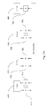
- FIG. 1 is an overall system block diagram of a system 10 and corresponding components for providing a virtual patrol functionality.
- major elements of system 10 preferably include a plurality of street light sensor units (SLSUs) 102 and a monitoring station 104.
- Each individual SLSU 108 preferably includes a light source 106 for illuminating a region connected to a sensor unit 100.
- Each individual sensor unit 100 preferably includes an image sensor 110 for capturing video data from a field of view that overlaps at least partially with the region illuminated by the light source 106, a communications subsystem 120 for transmitting and receiving data, and a data processing unit 130 for processing video data as well as actuating the communications subsystem 120.
- the light source 106 is physically connected to the sensor unit 100, the herein described embodiments, unless otherwise stated, are functional without a physically connected light source 106.
- Types of light sources include, but are not limited to, LED lights, incandescent light bulbs, halogen light bulbs, or other suitable sources that are capable of producing illumination.
- the data processing unit 130 preferably contains a processor 132 coupled to a storage medium such as a memory 134.
- the processor 132 can be any number of computer processors including, but not limited to a microprocessor, an ASIC, a DSP, a state machine, and a microcontroller. Such processors include, or may be in communication with computer readable media, which stores program code or instruction sets that, when executed by the processor, cause the processor to perform actions.
- Types of computer readable media include, but are not limited to, electronic, optical, magnetic, or other storage or transmission device capable of providing a processor with computer readable instructions.
- the communications subsystem 120 is configured to maintain a low bandwidth communication mode as actuated by the data processing unit 130.
- the low bandwidth communication mode configures the communications subsystem 120 to remain silent and not transmit video data until explicitly and individually requested to do so.
- the SLSUs may be deployed in any suitable location, including, but not limited to, roads, highways, parking lots, public parks, and airports.
- the SLSUs 102 are deployed such that physically adjacent sensor units have overlapping fields of view.
- the overlapping fields of view of physically adjacent sensor units provide continuous video coverage of a scene.
- each individual SLSU 108 is in networked communication with the monitoring station 104, as depicted in FIG. 1 .
- Major elements of the monitoring station 104 preferably include a communications module 140, a data processing system 150, and a graphical user interface 160.
- the communications module 140 is preferably configured such that it is in networked communication with the communications subsystems 120 of each SLSU 108.
- the data processing system 150 may contain a processor 152 coupled to a storage medium such as memory 154.
- the graphical user interface 160 is connected to a user input device 164 as well as a display 162 for displaying data received from a SLSU.
- the types of data displayed on the display 162 may include, but is not limited to, video data, geographic information, SLSU information, and satellite maps or other maps with sensor geographic positions.
- a specific example may be a satellite map on the display 162 combined with the geographic location of a particular SLSU from the series of SLSUs 102.
- the geographic location of the particular SLSU may be represented by colored dot overlaid on the satellite map.
- the user input device 164 may be any suitable device for providing input, including, but not limited to, a keyboard, mouse, joystick, or a voice recognition system.
- the processor 152 can be any number of computer processors including, but not limited to a microprocessor, an ASIC, a DSP, a state machine, and a microcontroller. Such processors include, or may be in communication with computer readable media, which stores program code or instruction sets that, when executed by the processor, cause the processor to perform actions. Types of computer readable media include, but are not limited to, electronic, optical, magnetic, or other storage or transmission device capable of providing a processor with computer readable instructions.
- the communication may include, but is not limited to direct networked communication, communication via an intermediate cloud server, or other suitable paradigms.
- the communications subsystem 120 of FIG. 1 listens for incoming video data requests 210 from the monitoring station 104 or other systems in networked communication with the communications subsystem 120. Subsequent to a video data request 210, the real-time video data stream captured 220 by the image sensor is transmitted to the destination address of the device which sent the video data request 210, preferably to the monitoring station 104.
- the data processing unit 130 of FIG. 1 may additionally process 240 the video data captured 220 from the image sensor 110 of FIG. 1 prior to transmission 230.
- the processing may include, but is not limited to, compression, sampling, trimming, filtering, warping, and/or any other suitable processing request.
- indirect communication between the communications module 140 and the communications subsystems 120 of each SLSU 108 is also possible.
- high bandwidth data from a SLSU 108 may be transmitted to the monitoring station 104 via a cloud server.
- high bandwidth data from a SLSU 108 may be first uploaded to a cloud server and subsequently downloaded by the monitoring station 104 for processing.
- Other suitable communication paradigms are also possible.
- the user input device 164 is configured to receive input 310 from a user to generate 320 and send a video request 330 to a specifically selected SLSU.
- the video request 330 is sent to the communications module 140 via the data processing system 150.
- the communications subsystem 120 of the selected SLSU receives the video request 340 from the communications module 140.
- the monitoring station 104 will also send a video request 340' to an additional SLSU that has an overlapping field of view with the selected sensor.
- a single SLSU may have overlapping fields of view with multiple distinct SLSUs; however FIG.
- the selected SLSU and the additional SLSU may transmit 350, 350' recorded full quality video data 360, 360' to the monitoring station for processing.
- the data processing system 150 Upon receiving the video data 370 from each of the requested SLSUs, the data processing system 150 performs a video stitching algorithm 380 which may provide a single stitched video image. At least part of the stitched video image corresponding to the currently desired field of view is displayed 390 via the display 162 of the graphical user interface 160.
- the data processing system 150 may automatically send an END-TRANSMIT instruction 392 to a SLSU upon the condition that video data from that unit is no longer necessary for providing a single stitched video image.
- a SLSU will end video transmission.
- the user input device 164 may also be further configured to initiate sending of an END-TRANSMIT instruction 392 to a SLSU.
- the data processing system of each SLSU may also perform processing on the video data prior to transmission. Processing may include, but is not limited to, compression, sampling, trimming, filtering, warping, and/or any other suitable processing requested by the monitoring station 104.
- the data processing system 150 may perform processing techniques which restore the received video data to full content, and subsequently may perform a video stitching algorithm which may provide a single stitched video image.
- a plurality of SLSUs 102 in combination with a monitoring station 104 are deployed as described in FIG. 1 .
- the SLSUs 102 are preferably deployed in spaced relation such that physically adjacent SLSUs have overlapping fields of view. This overlap enables the particular "virtual patrol" functionality, as will be described in more detail below.
- Many spatial arrangements are possible, including, but not limited to, SLSUs deployed in an elongated array, SLSUs deployed in a circular or oblong arrangement, SLSUs deployed in a triangular arrangement, SLSUs deployed in a polygonal arrangement, and SLSUs deployed at different heights. Referring to FIG.
- the first SLSU 410 has a field of view that is contained within the space between a first set of field of view boundary edges 412, 412'.
- the second SLSU 420 has a field of view that is contained within the space between a second set of field of view boundary edges 422, 422'.
- the third SLSU 430 has a field of view that is contained within the space between a third set of field of view boundary edges 432, 432'.
- the fourth SLSU 440 has a field of view that is contained within the space between a fourth set of field of view boundary edges 442,442'.
- the field of view of the first SLSU 410 overlaps with the field of view of the second SLSU 420.
- the field of view of the second SLSU 420 additionally overlaps with the field of view of the third SLSU 430.
- the field of view of the third SLSU 430 additionally overlaps with the field of view of the fourth SLSU 440.
- An object 450 is contained within the fields of view of the second SLSU 420 as well as the third SLSU 430.
- the system and corresponding method provide a "virtual patrol” functionality.
- virtual patrol is used herein to describe a process of visually monitoring an extended area, as if progressing along a route, without the operator actually traveling. Practically, this is achieved by allowing virtual panning within stitched video images derived from image sensors with overlapping fields of view, and dynamically switching the group of image sensors transmitting video data in order to allow dynamically changing coverage of the stitched video image as the instantaneous field of view progresses along an array of image sensors.
- an operator of the "virtual patrol” is not limited to smooth progressive movement along a route, and can typically jump to any particular location selected, for example, on a map.
- the ability to perform virtual panning in video images over an extended area provides an intuitive interface and greatly improves situational awareness compared to abrupt switching between difference camera views from differing viewpoints. An exemplary implementation of this feature will now be described.
- the transmit and receive processing flow may follow a similar flow to that illustrated in FIG. 3 .
- the user input device 164 of FIG. 1 may be used to virtually pan through the stitched video image.
- FIGS. 5-6C the virtual pan capability is described by example.
- the elongated array configuration of FIG. 4 is used for illustration.
- the four image sensors illustrated here are typically at some arbitrary location along an extended array of image sensors, which may number many tens, or hundreds of sensors, or possibly thousands of image sensors in a case of city-wide coverage. Prior to any user request for video from a specific location, all of these many image sensors are preferably maintaining their low bandwidth mode.
- the monitoring station 104 of FIG. 4 Upon receipt of a video request from an operator seeking to receive video images from a location corresponding to the second sensor 420, the monitoring station 104 of FIG. 4 transmits a video request to second sensor 420 and additional video requests to the first and third SLSUs 410, 430.
- FIG. 5A depicts the resulting transmit and receive configurations of the four SLSUs.
- the first three SLSUs 410, 420, 430 transmit video data 510, 520, 530 and are also configured to receive 512, 522, 532 command and control messages from the monitoring station.
- the current video image 600 is derived from a stitched video image 602 and displayed via the graphical user interface 160.
- Stitched video image 602 is stitched from video images 610, 620, 630 derived, respectively, from the first three SLSUs 410, 420, 430 that are transmitting video data 510, 520, 530 ( FIG. 5A ).
- the region 640, corresponding to the field of view of SLSU 440 is not available, since SLSU 440 remains in low-bandwidth mode (like other SLSUs in the system that are not shown), monitor for video data transmission requests 542.
- FIG. 6B as the user operates input device 164 of FIG. 1 to request panning to the right, the portion of stitched image 602 provided as the current video image 600 pans across the stitched image.
- the portion of stitched image 602 provided as the current video image 600 pans across the stitched image.
- data from image 610 is no longer required for generating the current image 600, and the system identifies that the requested field of view is moving towards the region covered by SLSU 440. Accordingly, the monitoring station transmits an END-TRANSMIT instruction to SLSU 410 and a transmit request to SLSU 440. After this switch-over, a new stitched video image 604 including regions 620, 630, 640 is generated, thus allowing continued virtual panning into the region corresponding to the field of view of SLSU 440, as illustrated in FIG. 6C .
- the updated transmit and receive configurations for the four SLSUs is depicted in FIG. 5B . This hand-over process can be performed repeatedly, allowing the operator to perform a continuous virtual panning motion along a region covered by an array of image sensors.
- SLSUs cover multiple intersecting paths, such as in a system giving coverage of a system of roads
- a suitable user input can be used to select which of a plurality of available paths should be selected for continued virtual panning through a junction.
- SLSUs transmitting in groups of three is a non-limiting example.
- it may be preferable to have more than three units transmitting at a time for example, four units, which allows the upcoming unit to be actuated before another unit is stopped, or five units including two on either side of the current viewing location.
- the use of three SLSUs transmitting at one time may offer a particular synergy with power line communications where a three-phase electrical power supply is available.
- the system can ensure that only one video data transmission needs to be transferred on each phase at any given time, thereby simplifying encoding requirements and/or avoiding bandwidth limitations which might otherwise be encountered.
- the PLC protocol used has sufficient bandwidth to carry more than one video transmission in parallel, and connections to the different phases of the electrical supply occurs in an arbitrary manner according to the existing power supply architecture of the streetlight grid.
- a line control unit 500 in direct or indirect data communication with the monitoring station 104, is connected to all three phases and relays data to and from each of the phases, rendering the entire system phase-independent.
- An example of the above described implementation is shown in FIG. 5C .
- the SLSUs preferably maintain the low-bandwidth mode indefinitely until video data is requested, the SLSUs preferably perform continuous recording and processing of video data from their respective fields of view.
- the recorded data serves as an archive which can be called up from the monitoring station for viewing later, and provides a basis for monitoring for a range of different conditions under which an alarm signal or other prompt may be sent to the monitoring station.
- the data processing unit 130 of each SLSU 108 is configured to perform video processing algorithms or techniques on video data captured by the SLSU image sensor 110 in order to generate and transmit an alert to the monitoring station 104 or other systems in networked communication with the communications subsystem 120.
- Types of video processing algorithms and supplementary processing techniques may include, but are not limited to, pattern/object recognition algorithms, object tracking algorithms, anomaly detection algorithms, machine learning algorithms (supervised or unsupervised), and hypothesis tests, as well as combinations of the above.
- An example of a nominal baseline may be a time-averaged or modal value of each pixel, corresponding to a static background image.
- the baseline definition preferably also includes information, either preset during installation or derived during the learning period, defining the type of activities considered "normal" within the field of view of the unit and/or what criteria are to be used to identify abnormal situations which should generate an alarm or other notification.
- the alarm signal conditions are predicated on predefined rules or rules established during a learning period, characterized by the movement of objects in a monitoring region. The movement of objects which violates any or all of the rules may generate an alarm.
- the rules may depend on the specific scene which the field of view is monitoring.
- the nominal baseline is stored in a suitable format in the memory 134 associated with the data processing unit 130.
- video data captured by the image sensor 110 is sent to the data processing unit 130 for analytical comparison with the nominal baseline stored in the memory 134 using any suitable technique.
- the analytical comparison will preferably generate a score for the video data streams according to a metric relating to each of the potential alarm criteria defined in force for the given SLSU.
- video data streams which score above a given statistically significant threshold defined for each alarm condition metric will generate a corresponding event alert signal.
- Events may be defined depending on the specific scene which the field of view is monitoring. For example, if the field of view is observing a highway, the nominal baseline activity constitutes motor vehicles traveling at a predetermined minimum speed.
- the categorization of expected content included within the SLSU field of view may be defined by an operator, or may be automatically derived during a learning period or recalibration period.
- types of events which may satisfy an alert criterion may include, but are not limited to, a motor vehicle stopped on the highway, a collision of motor vehicles, a pedestrian moving on the highway, a pedestrian motionless on the highway, or an object obstructing one or more lanes of the highway.
- FIG. 1 and FIG. 7 a specific example of a first SLSU 108a and an additional SLSU 108b with overlapping fields of view is depicted for illustration purposes.
- Two SLSUs 108a, 108b record 702, 704 video data captured from respective image sensors.
- the first SLSU 108a processes 706 video data captured 702 from its image sensor.
- the data processing unit of the first sensor 108a generates an alert 708 and actuates the communications subsystem to transmit 710 the generated alert to the monitoring station 104.
- the communications subsystem of the first sensor waits for a video request 712 from the monitoring station 104, maintaining the low bandwidth mode of communication.
- the remaining processing steps are parallel to those described above with reference to FIG. 3 .
- the monitoring station 104 may display 720 a map with the geographic location of the SLSU 108a that issued the alert.
- a user input device 164 including, but not limited to a mouse, keyboard, joystick, touch-screen input or voice recognition system, is used to interactively select 722 the SLSU 108a that issued the alert.
- the data processing system 150 may generate a video request 724 addressed to the selected SLSU 108a and to additional SLSUs 108b which have fields of view that overlap the field of view associated with the selected SLSU 108a.
- the video requests 724 are transmitted 726 to the specified SLSUs 108a,108b.
- each specified SLSU 108a,108b transmits video data 728,730 to the monitoring station 104.
- the monitoring station 104 receives 732 and processes 734 the different video data feeds in order to produce the stitched video image discussed in previous embodiments.
- the stitched video image is displayed 736 via the graphical user interface 160.
- the user input device 164 may subsequently be used to perform the virtual panning action as described in previous embodiments.
- the data processing system of each SLSU may also perform processing on the video data prior to transmission. Processing may include, but is not limited to, compression, sampling, trimming, filtering, or any other suitable processing requested by the monitoring station 104.
- the data processing system 150 may perform processing techniques which restore the received video data to full content, and subsequently may perform a video stitching algorithm which may provide a single stitched video image.
- the present invention can clearly be implemented using a dedicated infrastructure where feasible, it is a particularly preferred feature of certain implementations of the invention that it lends itself easily to installation based primarily, if not exclusively, on commonplace existing infrastructure.
- the SLSUs of the present invention can advantageously be implemented for installation in conventional streetlight poles, which typically provide vantage points spaced at roughly regular intervals along roads in combination with an electrical power supply provided along power lines which can also be used for power-line communication.
- the light source 106 and sensor unit 100 of FIG. 1 are preferably contained within a common housing and are preferably fed by a single connection to the electrical power supply, to facilitate faster and easier installation on existing infrastructure.
- installation of SLSUs according to the present invention becomes a particularly cost-effective proposition for upgrading conventional street lights over an extended region.
- FIG. 10 is an overall system block diagram showing an embodiment of a representative SLSU 1000 with multiple sensors 1006, 1008, 1010, an LED lighting unit 1002, a PLC adapter 1004, an infrared (IR) imaging device 1012 for capturing video data in environments lacking in visible light, and a microwave (MW) imaging device 1014 for capturing the movement of objects in environments where the visibility of the objects in obstructed by edifices or the like.
- IR infrared
- MW microwave
- the SLSU 1000 can be used as a "smart street light" platform for providing a wide range of other functions, including various data collection, data output and communications functions.
- additional sensors that may be integrated with a SLSU 1000, include, but not limited to, temperature sensors 1006 for collecting temperature data, luminance sensors 1008 for detecting ambient light, and wind sensors 1010 for detecting wind velocity.
- SLSU 1000 may also include communication components for implementing daisy-chained WIFI access points and/or include cellular repeater stations and/or other hardware solutions for providing communications access to nearby or passing users. Local image processing may also automatically derive traffic congestion information, which may be shared via the communications network while remaining in low bandwidth mode.
- the multiple sensors 1006, 1008, 1010 in combination with the monitoring station 104 of FIG. 4 are preferably used to intelligently control the illumination level of each SLSU LED lighting unit 1002.
- the LED lighting unit 1002 is preferably turned off or dimmed.
- Another example is a SLSU which has been deployed in an isolated area. At night, when the luminance sensor 1008 detects no sunlight or other sources of visible light, it may seem logical that the LED lighting unit 1002 operate at a high illumination level to provide visibility for vehicles and other passersby.
- traffic information coupled with data collected from other sensors in the SLSU as well as other SLSUs may be indicative of conditions for which minimal or no lighting is necessary. Such conditions may include, but are not limited to, no passing vehicle traffic and no passing pedestrian traffic within a defined distance, or travel time, from the SLSU. In such conditions, the LED lighting unit 1002 is preferably dimmed to a reduced illumination level.
- communication between the monitoring station 104 and SLSUs 102 is via a wireless network, including, but not limited to, GSM, CDMA, 4G, LTE, Wi-Fi, or WiMax.
- a wireless network including, but not limited to, GSM, CDMA, 4G, LTE, Wi-Fi, or WiMax.
- Different communications protocols may be used for the transmission and reception of different types of data. For example, alerts or video requests are preferably transmitted and received by using Power Line Communication technology, while video data is preferably transmitted and received by using a cellular broadband protocol such as LTE.
- both the monitoring station 104 and SLSUs 102 are equipped with audio sensors and speaker systems.
- Types of audio sensors may include, but are not limited to, microphones, Doppler sensors, or any other suitable device for capturing and/or measuring audio.
- Voice communications is established via any of the wired or wireless network protocols discussed in previous embodiments. Voice communication modes may be any suitable mode of communication, including, but not limited to, point-to-point, point-to-multipoint, half-duplex, and full-duplex.
- the monitoring station 104 is preferably configured to request audio data from a selectively specified SLSU 108.
- the process of the monitoring station requesting and receiving audio data, and a SLSU receiving an audio request and transmitting audio data is logically similar to the video data request process described in FIG. 2A and FIG. 3 .
- emergency responder intercom contact may be initiated by a passerby at the SLSU by actuating an emergency call button or the like associated with the SLSU. This would preferably also generate a prioritized alarm signal to the operator of the monitoring system to prompt the operator to view the corresponding region and initiate appropriate action to address any emergency that may have occurred.
- the monitoring station of FIG. 1 is deployed remotely from the SLSUs 102.
- FIG. 8 depicts the monitoring station of FIG. 1 and additional database component 840.
- the user input device 834 is preferably configured to receive input from a user to generate and send a video request to a specifically addressed device that is in communication with the communications module 810. Additional video requests are preferably sent to the address of a device, or devices, that are physically adjacent to the specifically addressed device.
- a mapping which relates the physical location of devices to the network address of devices is preferably stored in any suitable location, including, but not limited to, the memory 824 of the monitoring station 800, the cloud, or as illustrated in FIG. 8 , a database or table 840 which is preferably associated with the data processing system 820.
- FIGS. 9A-9B an example of five devices in physical space and the database 840 which associates the physical location of each device with a network address is illustrated.
- a video request may also be sent to the device, or devices, closest in physically proximity, which in this case is Device 2 920, in location D.
- the example database entry in FIG. 9B shows the mapping of device location and network address.
- the devices to be addressed have addresses a 942 and e 922. Any change to the number of devices is preferably reflected in an update to the mapping.
- the operation of the system as described thus far has related primarily to viewing and "patrolling" real-time video data
- certain particularly preferred implementations of the invention allow the operator to view data previously stored in one or more of the SLSUs, and most preferably, to perform virtual panning ("patrolling") within that historical data as if viewing it in real-time.
- the video requests preferably include a timestamp flag which will either correspond to the date and time of the video being requested or will flag the video request as a real-time video request for the video currently being sampled.
- any subsequent instructions for a new given SLSU to start transmitting will also include a corresponding timestamp in order for the newly added video data for stitching to be synchronized with the currently transmitted data from the actively transmitting SLSUs.
- SLSU 108 comprised of a street light 106 connected to a sensor unit 100 as described in FIG. 1
- sensor unit 100 may be deployed in conjunction with a monitoring station 104 as described above, with the operation of the system primarily for viewing and "patrolling" real-time video data, as well as “patrolling” historical video.
Landscapes
- Engineering & Computer Science (AREA)
- Multimedia (AREA)
- Signal Processing (AREA)
- Human Computer Interaction (AREA)
- Closed-Circuit Television Systems (AREA)
- Alarm Systems (AREA)
Applications Claiming Priority (1)
| Application Number | Priority Date | Filing Date | Title |
|---|---|---|---|
| US201361847585P | 2013-07-18 | 2013-07-18 |
Publications (1)
| Publication Number | Publication Date |
|---|---|
| EP2827578A1 true EP2827578A1 (fr) | 2015-01-21 |
Family
ID=51211619
Family Applications (1)
| Application Number | Title | Priority Date | Filing Date |
|---|---|---|---|
| EP14177556.9A Withdrawn EP2827578A1 (fr) | 2013-07-18 | 2014-07-17 | Système de surveillance vidéo virtuelle et composants associés |
Country Status (5)
| Country | Link |
|---|---|
| US (1) | US9736369B2 (fr) |
| EP (1) | EP2827578A1 (fr) |
| CA (1) | CA2856896A1 (fr) |
| IN (1) | IN2014MU02329A (fr) |
| RU (1) | RU2014129398A (fr) |
Cited By (1)
| Publication number | Priority date | Publication date | Assignee | Title |
|---|---|---|---|---|
| US20190356866A1 (en) * | 2018-05-15 | 2019-11-21 | Eaton Intelligent Power Limited | Frame Stitching And Other Functions Using Multiple Cameras |
Families Citing this family (11)
| Publication number | Priority date | Publication date | Assignee | Title |
|---|---|---|---|---|
| US11226856B2 (en) * | 2015-04-24 | 2022-01-18 | Senslytics Corporation | Methods and systems correlating hypotheses outcomes using relevance scoring for intuition based forewarning |
| CN105100829B (zh) * | 2015-06-29 | 2019-07-02 | 小米科技有限责任公司 | 视频内容截取方法及装置 |
| JP6434396B2 (ja) * | 2015-12-10 | 2018-12-05 | 日本電信電話株式会社 | センサデータ収集システムおよび方法 |
| CN106816164B (zh) * | 2017-02-17 | 2019-05-17 | 盐城工学院 | 音频播放方法及广场照明系统 |
| WO2019040283A1 (fr) * | 2017-08-23 | 2019-02-28 | Siemens Healthcare Diagnostics Inc. | Système de vision destiné au travail de laboratoire |
| CN107995467A (zh) * | 2017-12-19 | 2018-05-04 | 内江师范学院 | 一种远程视频监控系统 |
| TWI644293B (zh) * | 2017-12-27 | 2018-12-11 | 中興保全股份有限公司 | 巡邏勤務系統及其驗證方法 |
| US11417109B1 (en) * | 2018-03-20 | 2022-08-16 | Amazon Technologies, Inc. | Network-based vehicle event detection system |
| CN111556280A (zh) | 2019-02-12 | 2020-08-18 | 昆山纬绩资通有限公司 | 设备状态监控方法与系统 |
| US10778887B1 (en) * | 2019-05-30 | 2020-09-15 | Ambarella International Lp | Security application using camera SOC with multi-sensor capabilities |
| US20230058472A1 (en) * | 2020-01-28 | 2023-02-23 | Gopro, Inc. | Sensor prioritization for composite image capture |
Citations (7)
| Publication number | Priority date | Publication date | Assignee | Title |
|---|---|---|---|---|
| WO1993019441A1 (fr) * | 1992-03-20 | 1993-09-30 | Commonwealth Scientific And Industrial Research Organisation | Systeme de surveillance de la circulation |
| US20050185047A1 (en) * | 2004-02-19 | 2005-08-25 | Hii Desmond Toh O. | Method and apparatus for providing a combined image |
| US20060056855A1 (en) * | 2002-10-24 | 2006-03-16 | Masao Nakagawa | Illuminative light communication device |
| EP2242252A2 (fr) * | 2009-04-17 | 2010-10-20 | Sony Corporation | Génération par caméra d'images panoramiques composites de haute qualité |
| US20120098925A1 (en) | 2010-10-21 | 2012-04-26 | Charles Dasher | Panoramic video with virtual panning capability |
| US20120169842A1 (en) * | 2010-12-16 | 2012-07-05 | Chuang Daniel B | Imaging systems and methods for immersive surveillance |
| US20130129304A1 (en) * | 2011-11-22 | 2013-05-23 | Roy Feinson | Variable 3-d surround video playback with virtual panning and smooth transition |
Family Cites Families (18)
| Publication number | Priority date | Publication date | Assignee | Title |
|---|---|---|---|---|
| US6175382B1 (en) * | 1997-11-24 | 2001-01-16 | Shell Oil Company | Unmanned fueling facility |
| US7051356B2 (en) | 2002-02-25 | 2006-05-23 | Sentrus, Inc. | Method and system for remote wireless video surveillance |
| WO2004004320A1 (fr) | 2002-07-01 | 2004-01-08 | The Regents Of The University Of California | Traitement numerique d'images video |
| FR2874299B1 (fr) * | 2004-08-12 | 2007-05-25 | Ile Immobiliere Magellan 2 Soc | Procede pour l'installation d'un equipement mixte sur un equipement de mobilier urbain |
| AU2005306167B8 (en) * | 2004-11-18 | 2010-11-18 | Powersense A/S | Compensation of simple fiberoptic faraday effect sensors |
| IN2007KN02527A (fr) | 2005-01-03 | 2015-10-16 | Vumii Inc | |
| EP1713206A1 (fr) | 2005-04-11 | 2006-10-18 | Last Mile Communications/Tivis Limited | Réséau de communication distribué comprenant des stations de base connectées sans fil |
| EP2238758A4 (fr) * | 2008-01-24 | 2013-12-18 | Micropower Technologies Inc | Systèmes de distribution de vidéo utilisant des caméras sans fil |
| US9202358B2 (en) * | 2008-02-04 | 2015-12-01 | Wen Miao | Method and system for transmitting video images using video cameras embedded in signal/street lights |
| US9215781B2 (en) * | 2008-04-16 | 2015-12-15 | Avo Usa Holding 2 Corporation | Energy savings and improved security through intelligent lighting systems |
| EP2308197A4 (fr) | 2008-07-31 | 2014-04-16 | Inovus Solar Inc | Éclairage d'extérieur autonome sans fil alimenté par l'énergie solaire et réseau de gestion d'énergie et d'informations |
| US8736678B2 (en) * | 2008-12-11 | 2014-05-27 | At&T Intellectual Property I, L.P. | Method and apparatus for vehicle surveillance service in municipal environments |
| US20100253318A1 (en) * | 2009-02-02 | 2010-10-07 | Thomas Sr Kirk | High voltage to low voltage inductive power supply with current sensor |
| CN101545599B (zh) | 2009-04-23 | 2011-11-16 | 深圳万润科技股份有限公司 | 路灯以及监控装置 |
| US20130107041A1 (en) * | 2011-11-01 | 2013-05-02 | Totus Solutions, Inc. | Networked Modular Security and Lighting Device Grids and Systems, Methods and Devices Thereof |
| CN102665365A (zh) | 2012-05-29 | 2012-09-12 | 广州中国科学院软件应用技术研究所 | 一种基于来车视频检测的路灯控制管理系统 |
| CN102857739B (zh) | 2012-08-20 | 2015-09-09 | 上海光亮光电科技有限公司 | 分布式全景监控系统及其方法 |
| CN102938827B (zh) | 2012-11-29 | 2016-05-11 | 深圳英飞拓科技股份有限公司 | 一种分层监控指挥系统及跨摄像头虚拟跟踪方法 |
-
2014
- 2014-07-14 CA CA2856896A patent/CA2856896A1/fr not_active Abandoned
- 2014-07-15 US US14/331,251 patent/US9736369B2/en not_active Expired - Fee Related
- 2014-07-17 RU RU2014129398A patent/RU2014129398A/ru not_active Application Discontinuation
- 2014-07-17 EP EP14177556.9A patent/EP2827578A1/fr not_active Withdrawn
- 2014-07-18 IN IN2329MU2014 patent/IN2014MU02329A/en unknown
Patent Citations (7)
| Publication number | Priority date | Publication date | Assignee | Title |
|---|---|---|---|---|
| WO1993019441A1 (fr) * | 1992-03-20 | 1993-09-30 | Commonwealth Scientific And Industrial Research Organisation | Systeme de surveillance de la circulation |
| US20060056855A1 (en) * | 2002-10-24 | 2006-03-16 | Masao Nakagawa | Illuminative light communication device |
| US20050185047A1 (en) * | 2004-02-19 | 2005-08-25 | Hii Desmond Toh O. | Method and apparatus for providing a combined image |
| EP2242252A2 (fr) * | 2009-04-17 | 2010-10-20 | Sony Corporation | Génération par caméra d'images panoramiques composites de haute qualité |
| US20120098925A1 (en) | 2010-10-21 | 2012-04-26 | Charles Dasher | Panoramic video with virtual panning capability |
| US20120169842A1 (en) * | 2010-12-16 | 2012-07-05 | Chuang Daniel B | Imaging systems and methods for immersive surveillance |
| US20130129304A1 (en) * | 2011-11-22 | 2013-05-23 | Roy Feinson | Variable 3-d surround video playback with virtual panning and smooth transition |
Cited By (2)
| Publication number | Priority date | Publication date | Assignee | Title |
|---|---|---|---|---|
| US20190356866A1 (en) * | 2018-05-15 | 2019-11-21 | Eaton Intelligent Power Limited | Frame Stitching And Other Functions Using Multiple Cameras |
| WO2019219245A1 (fr) * | 2018-05-15 | 2019-11-21 | Eaton Intelligent Power Limited | Assemblage de trames et autres fonctions en utilisant de multiples appareils de prise de vues |
Also Published As
| Publication number | Publication date |
|---|---|
| CA2856896A1 (fr) | 2015-01-18 |
| US20150022630A1 (en) | 2015-01-22 |
| RU2014129398A (ru) | 2016-02-10 |
| IN2014MU02329A (fr) | 2015-08-28 |
| US9736369B2 (en) | 2017-08-15 |
Similar Documents
| Publication | Publication Date | Title |
|---|---|---|
| US9736369B2 (en) | Virtual video patrol system and components therefor | |
| US11123876B2 (en) | Method for sensor data processing | |
| JP7061964B2 (ja) | データ生成方法及びデータ生成装置 | |
| JP6190369B2 (ja) | 屋外照明ネットワークを使用する撮像サービス | |
| JP7402695B2 (ja) | 情報送信方法及びクライアント装置 | |
| KR102029656B1 (ko) | 사물인터넷기반 임베디드 방식의 교통신호 자율운영시스템 | |
| JP6602303B2 (ja) | 拡張現実を支援するためのシステム及び方法 | |
| JP7190820B2 (ja) | 侵入検知システムおよび侵入検知方法 | |
| CN104833368A (zh) | 实景导航系统及方法 | |
| WO2012051043A2 (fr) | Système et procédé d'interface d'affichage électronique de feux de circulation | |
| KR102188850B1 (ko) | 무선통신을 이용한 블랙아이스 분석시스템 | |
| WO2007015631A1 (fr) | Systeme de videosurveillance intelligent et procede de communication avec un systeme de radar a poursuite automatique | |
| WO2012137367A1 (fr) | Système d'accumulation d'images | |
| CN113074714A (zh) | 一种基于多数据融合的多态势感知传感器及其处理方法 | |
| KR20220083533A (ko) | LiDAR 정보와 카메라 정보의 병합 | |
| CN107784843A (zh) | 智能交通信号灯系统及其图像处理方法 | |
| KR101479178B1 (ko) | 가로등을 대체할 수 있는 cctv용 지능형 카메라장치 | |
| JP2013109639A (ja) | 画像処理装置、サーバ、携帯端末装置、及び画像処理方法 | |
| JP7459932B2 (ja) | 遠隔監視システム、装置、方法、及びプログラム | |
| CN104702967B (zh) | 虚拟视频巡检系统与其组件 | |
| WO2020039798A1 (fr) | Dispositif de fourniture d'informations, procédé de fourniture d'informations, programme de fourniture d'informations et structure de données | |
| JP7348724B2 (ja) | 車載装置および表示方法 | |
| JP2003523647A (ja) | 閉回路テレビジョン(cctv)カメラおよびシステム | |
| JP5790788B2 (ja) | 監視システム | |
| CN103139539A (zh) | 一种全景监视系统 |
Legal Events
| Date | Code | Title | Description |
|---|---|---|---|
| 17P | Request for examination filed |
Effective date: 20140717 |
|
| AK | Designated contracting states |
Kind code of ref document: A1 Designated state(s): AL AT BE BG CH CY CZ DE DK EE ES FI FR GB GR HR HU IE IS IT LI LT LU LV MC MK MT NL NO PL PT RO RS SE SI SK SM TR |
|
| AX | Request for extension of the european patent |
Extension state: BA ME |
|
| PUAI | Public reference made under article 153(3) epc to a published international application that has entered the european phase |
Free format text: ORIGINAL CODE: 0009012 |
|
| R17P | Request for examination filed (corrected) |
Effective date: 20150721 |
|
| RBV | Designated contracting states (corrected) |
Designated state(s): AL AT BE BG CH CY CZ DE DK EE ES FI FR GB GR HR HU IE IS IT LI LT LU LV MC MK MT NL NO PL PT RO RS SE SI SK SM TR |
|
| STAA | Information on the status of an ep patent application or granted ep patent |
Free format text: STATUS: THE APPLICATION IS DEEMED TO BE WITHDRAWN |
|
| 18D | Application deemed to be withdrawn |
Effective date: 20180201 |