EP2827470A1 - Charging device for secondary battery, and charging method for secondary battery - Google Patents
Charging device for secondary battery, and charging method for secondary battery Download PDFInfo
- Publication number
- EP2827470A1 EP2827470A1 EP13761794.0A EP13761794A EP2827470A1 EP 2827470 A1 EP2827470 A1 EP 2827470A1 EP 13761794 A EP13761794 A EP 13761794A EP 2827470 A1 EP2827470 A1 EP 2827470A1
- Authority
- EP
- European Patent Office
- Prior art keywords
- charging
- electric power
- full charge
- storage battery
- stop time
- Prior art date
- Legal status (The legal status is an assumption and is not a legal conclusion. Google has not performed a legal analysis and makes no representation as to the accuracy of the status listed.)
- Granted
Links
Images




Classifications
-
- H—ELECTRICITY
- H02—GENERATION; CONVERSION OR DISTRIBUTION OF ELECTRIC POWER
- H02J—ELECTRIC POWER NETWORKS; CIRCUIT ARRANGEMENTS OR SYSTEMS FOR SUPPLYING OR DISTRIBUTING ELECTRIC POWER; SYSTEMS FOR STORING ELECTRIC ENERGY
- H02J7/00—Circuit arrangements for charging or discharging batteries or for supplying loads from batteries
- H02J7/90—Regulation of charging or discharging current or voltage
- H02J7/933—Regulation of charging or discharging current or voltage the cycle being controlled or terminated in response to electric parameters
-
- G—PHYSICS
- G01—MEASURING; TESTING
- G01R—MEASURING ELECTRIC VARIABLES; MEASURING MAGNETIC VARIABLES
- G01R31/00—Arrangements for testing electric properties; Arrangements for locating electric faults; Arrangements for electrical testing characterised by what is being tested not provided for elsewhere
- G01R31/36—Arrangements for testing, measuring or monitoring the electrical condition of accumulators or electric batteries, e.g. capacity or state of charge [SoC]
- G01R31/382—Arrangements for monitoring battery or accumulator variables, e.g. SoC
-
- H—ELECTRICITY
- H01—ELECTRIC ELEMENTS
- H01M—PROCESSES OR MEANS, e.g. BATTERIES, FOR THE DIRECT CONVERSION OF CHEMICAL ENERGY INTO ELECTRICAL ENERGY
- H01M10/00—Secondary cells; Manufacture thereof
- H01M10/42—Methods or arrangements for servicing or maintenance of secondary cells or secondary half-cells
- H01M10/44—Methods for charging or discharging
- H01M10/443—Methods for charging or discharging in response to temperature
-
- H—ELECTRICITY
- H02—GENERATION; CONVERSION OR DISTRIBUTION OF ELECTRIC POWER
- H02J—ELECTRIC POWER NETWORKS; CIRCUIT ARRANGEMENTS OR SYSTEMS FOR SUPPLYING OR DISTRIBUTING ELECTRIC POWER; SYSTEMS FOR STORING ELECTRIC ENERGY
- H02J7/00—Circuit arrangements for charging or discharging batteries or for supplying loads from batteries
- H02J7/90—Regulation of charging or discharging current or voltage
- H02J7/971—Regulation of charging or discharging current or voltage the charge cycle being controlled or terminated in response to non-electric parameters
- H02J7/975—Regulation of charging or discharging current or voltage the charge cycle being controlled or terminated in response to non-electric parameters in response to temperature
- H02J7/977—Regulation of charging or discharging current or voltage the charge cycle being controlled or terminated in response to non-electric parameters in response to temperature of the battery
-
- H—ELECTRICITY
- H02—GENERATION; CONVERSION OR DISTRIBUTION OF ELECTRIC POWER
- H02J—ELECTRIC POWER NETWORKS; CIRCUIT ARRANGEMENTS OR SYSTEMS FOR SUPPLYING OR DISTRIBUTING ELECTRIC POWER; SYSTEMS FOR STORING ELECTRIC ENERGY
- H02J7/00—Circuit arrangements for charging or discharging batteries or for supplying loads from batteries
- H02J7/90—Regulation of charging or discharging current or voltage
- H02J7/927—Regulation of charging or discharging current or voltage with introduction of pulses during the charging process
-
- Y—GENERAL TAGGING OF NEW TECHNOLOGICAL DEVELOPMENTS; GENERAL TAGGING OF CROSS-SECTIONAL TECHNOLOGIES SPANNING OVER SEVERAL SECTIONS OF THE IPC; TECHNICAL SUBJECTS COVERED BY FORMER USPC CROSS-REFERENCE ART COLLECTIONS [XRACs] AND DIGESTS
- Y02—TECHNOLOGIES OR APPLICATIONS FOR MITIGATION OR ADAPTATION AGAINST CLIMATE CHANGE
- Y02B—CLIMATE CHANGE MITIGATION TECHNOLOGIES RELATED TO BUILDINGS, e.g. HOUSING, HOUSE APPLIANCES OR RELATED END-USER APPLICATIONS
- Y02B40/00—Technologies aiming at improving the efficiency of home appliances, e.g. induction cooking or efficient technologies for refrigerators, freezers or dish washers
-
- Y—GENERAL TAGGING OF NEW TECHNOLOGICAL DEVELOPMENTS; GENERAL TAGGING OF CROSS-SECTIONAL TECHNOLOGIES SPANNING OVER SEVERAL SECTIONS OF THE IPC; TECHNICAL SUBJECTS COVERED BY FORMER USPC CROSS-REFERENCE ART COLLECTIONS [XRACs] AND DIGESTS
- Y02—TECHNOLOGIES OR APPLICATIONS FOR MITIGATION OR ADAPTATION AGAINST CLIMATE CHANGE
- Y02E—REDUCTION OF GREENHOUSE GAS [GHG] EMISSIONS, RELATED TO ENERGY GENERATION, TRANSMISSION OR DISTRIBUTION
- Y02E60/00—Enabling technologies; Technologies with a potential or indirect contribution to GHG emissions mitigation
- Y02E60/10—Energy storage using batteries
Definitions
- the present invention relates to charging control for a storage battery.
- a charging device for charging a storage battery As a charging device for charging a storage battery, a charging device configured to stop charging when a fully-charged state is detected after the start of charging and conduct recharging after elapse of a prescribed time period set in advance has been known (for example, JP 2005-124340 A ). As in the device, stopping charging for a prescribed time period after detection of an apparent fully-charged state and recharging allows an actual charge state of a battery to be closer to a fully-charged state.
- charging stop time a time period to stop charging (hereinafter referred to as charging stop time) after detection of a fully-charged state
- JP 2005-124340 A has a difficulty in setting an appropriate charging stop time.
- the charging stop time is too short, the actual charge state of a storage battery cannot be sufficiently made close to the fully-charged state.
- the charging stop time is too long, the time period from the start of charging to the end of recharging becomes unnecessarily longer.
- a charging device for a storage battery including: a charging power source for supplying electric power to a storage battery; charging electric power detecting means for detecting electric power charged from the charging power source to the storage battery; and full charge determining means for making a full charge determination when chargeable electric power calculated based on a detected value of the charging electric power detecting means drops to a prescribed electric power value set in advance or less.
- the charging device for a storage battery further includes charging controlling means for conducting charging by supplying electric power to the storage battery from the charging power source until the full charge determination is made, stopping electric power supply to the storage battery from the charging power source when the full charge determination is made, restarting charging after a prescribed time period elapses from the stop of electric power supply, and conducting charging until the full charge determination is made again.
- the charging device for a storage battery further includes: temperature detecting means for detecting a temperature of the storage battery; and stop time setting means for setting a stop time based on at least the temperature of the storage battery at the full charge determination. The stop time setting means sets the stop time to be longer as the temperature of the storage battery becomes lower.
- FIG. 1 is a configuration diagram of a charging system according to an embodiment of the present invention.
- the charging system includes a battery 3, a charger 2 for supplying charging electric power to the battery 3, and a controller 1 for controlling the charger 2.
- the charging system further includes a current sensor 4 for detecting a charging current supplied from the charger 2 to the battery 3, a voltage sensor 5 for detecting a voltage of the battery 3, and a temperature sensor 6 for detecting a temperature of the battery 3.
- the controller 1 calculates electric power charged from the charger 2 to the battery 3 based on detected values of the current sensor 4 and the voltage sensor 5 and sends, to the charger 2, a charging electric power command based on the calculated charging electric power. Moreover, the controller 1 also reads a detected value of the temperature sensor 6. The internal configuration of the controller 1 is described later.
- the charger 2 supplies, to the battery 3, charging electric power based on the charging electric power command sent from the controller 1.
- the battery 3 is, for example, a storage battery such as a lithium-ion battery that is used as a power source for driving a drive motor of an electric-powered car.
- the battery 3 is charged by the charging electric power supplied from the charger 2.
- the detected values of the current sensor 4, the voltage sensor 5, and the temperature sensor 6 are read by the controller 1.
- the controller 1 includes a chargeable electric power calculating unit 11, a charging electric power command unit 10, a timer 12, and a stop time setting unit 13.
- the chargeable electric power calculating unit 11 reads the detected values of the current sensor 4 and the voltage sensor 5, and calculates chargeable electric power based on the detected values.
- the chargeable electric power means electric power that can be charged to the battery 3 before the battery 3 reaches the fully-charged state.
- the charging electric power command unit 10 sends, to the charger 2, a charging electric power command based on the chargeable electric power calculated by the chargeable electric power calculating unit 11.
- the charging electric power command unit 10 determines that the battery is in the fully-charged state and stops charging, specifically sets the charging electric power command to zero (kW).
- the charging electric power command unit 10 sends a command for setting a charging stop time (hereinafter referred to as stop time setting command) to the stop time setting unit 13.
- the charging electric power command unit 10 After sending the stop time setting command, the charging electric power command unit 10 reads a count value of the timer 12 described later, and at the time point when the count value becomes zero, restarts sending, to the charger 2, a charging electric power command based on the chargeable electric power, to conduct so-called additional charging.
- the stop time setting unit 13 After receiving the stop time setting command sent from the charging electric power command unit 10, the stop time setting unit 13 calculates a stop time depending on the temperature of the battery and sets the calculated stop time on the timer 12. It should be noted that, while the details are described later, the stop time depending on the temperature of the battery is a time period set to be longer for a lower temperature of the battery.
- the timer 12 After the stop time is set by the stop time setting unit 13, the timer 12 starts countdown (a process of decreasing the count value every prescribed time period). It should be noted that the minimum value of the count value is zero.
- FIG. 2 is a flow chart of a charging control routine executed by the controller 1.
- Step S10 the controller 1 computes the chargeable electric power. More particularly, the chargeable electric power calculating unit 11 computes the chargeable electric power based on the detected values of the current sensor 4 and the voltage sensor 5, this chargeable electric power is sent to the charging electric power command unit 10, and the charging electric power command unit 10 sends the charging electric power command to the charger 2.
- a deviation between a full charge voltage set in advance and the detected value of the voltage sensor 5, specifically an increment of voltage ⁇ V to the fully-charged state is calculated.
- an increment of current ⁇ I to the fully-charged state is calculated by using the increment of voltage ⁇ V and a resistance R of the battery 3 measured in advance.
- an increment of electric power to the fully-charged state can be calculated by using the increment of voltage ⁇ V and the increment of current ⁇ I.
- Step S20 the controller 1 determines whether the battery 3 is in the fully-charged state or not by the charging electric power command unit 10. Specifically, when the chargeable electric power drops to a prescribed electric power value set in advance or less, the controller 1 makes a determination of the fully-charged state (this determination is hereinafter referred to as "full charge determination").
- the prescribed electric power value can be set to zero (kW) considering the purpose of the determination in this step, the chargeable electric power may not decrease to zero in case of a detection error of the respective sensors 4 and 5, or the like, which may result in failure in making the determination of the fully-charged state. Therefore, a value of almost near zero (kW) is set, by which the determination of the fully-charged state can be made even with a detection error of the respective sensors 4 and 5.
- Step S30 a process of Step S30 is executed, and when the full charge determination is not made, the process of Step S10 is executed again.
- the full charge determination is just a determination that the chargeable electric power drops to a prescribed electric power value or less and is not a determination that the battery 3 actually reaches the fully-charged state.
- Step S30 the controller 1 sets the charging stop time after the full charge determination by the stop time setting unit 13.
- the stop time setting unit 13 reads the detected value of the temperature sensor 6, determines the stop time with reference to a stop time map stored in advance, sets the determined set time on the timer 12, and allows the timer 12 to start countdown.
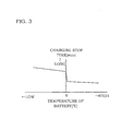
- On the stop time map a longer stop time is set for a lower temperature of the battery, as shown in FIG. 3 , for example. This is based on characteristics that the time period until polarization is eliminated becomes longer as the battery temperature becomes lower.
- polarization results from a difference in concentration caused by diffusion of a lithium-ion which is a diffusion material, and as the battery temperature becomes lower, it takes longer time to eliminate the difference in concentration due to a higher viscosity of an electrolyte. Therefore, setting a longer charging time for a lower temperature of the battery sufficiently eliminates polarization until restart of the charging.
- stop time map is not limited to that shown in FIG. 3 as long as the condition that a longer stop time is set for a lower temperature of the battery is satisfied.
- a temperature region may be divided into a plurality of sections and the stop time may be set for every section.
- Step S40 the controller 1 determines whether or not the number of times of the full charge determination reaches a prescribed number of times set in advance or higher with reference to a value of a counter for counting the number of times of the full charge determination installed in the charging electric power command unit 10.
- the prescribed number of times can be set arbitrarily, but for example, set to about 5 times.
- Step S50 the controller 1 increments the value of the counter for counting the number of times of the full charge determination.
- the counter for counting the number of times of the full charge determination increments its value every full charge determination in Step S20 until the value of the counter is determined to be equal to or higher than the prescribed number of times in Step S40.
- Step S60 the controller 1 sends, to the charger 2, a charging electric power command of zero (kW) by the charging electric power command unit 10, to stop charging.
- Step S70 the controller 1 determines whether the charging stop time passes or not by the charging electric power command unit 10. Specifically, whether the count value of the timer 12 becomes zero or not is determined.
- the process of Step S10 is executed again for additional charging, and when the charging stop time does not pass, the process of Step S60 is executed again.
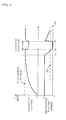
- FIG. 4 is a time chart in the case of executing the charging control described above.
- the chargeable electric power starts dropping.
- the full charge determination is made and charging is stopped once.
- additional charging is started. After that, stopping and restarting of charging is similarly repeated until the number of times of the full charge determination reaches the prescribed number of times or higher.
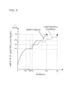
- FIG. 5 is a time chart of the amount of electric power charged to the battery 3.
- the solid line in FIG. 5 represents a case of executing the charging control of this embodiment.
- the broken line represents a case of employing a constant charging stop time regardless of the temperature of the battery. It should be noted that the temperature of the battery is, for example, around zero (°C).
- the amount of electric power reaches P4 which is the amount of electric power at the true fully-charged state at the timing T4 in this embodiment, but reaches at the timing T5 which is later than the timing T4 in the comparative example.
- the temperature sensor 6 for detecting the temperature of the battery 3 and the stop time setting unit 13 for setting a charging stop time based on at least the temperature of the battery at a full charge determination are provided, by which the charging stop time is set to be longer for a lower temperature of the battery. This enables efficient charging because the charging stop time becomes longer for a circumstance requiring a longer time to eliminate polarization due to a low temperature of the battery, which results in an increased amount of electric power charged by means of additional charging.
- a charging system of a second embodiment of the present invention is similar to the first embodiment in that charging is stopped after the full charge determination and additional charging is conducted after elapse of the charging stop time set based on the temperature of the battery, but differs from the first embodiment in that the charging stop time is corrected based on the number of times of the full charge determination.
- FIG. 6 is a flow chart illustrating an example of a charging control routine conducted by the controller 1 in the second embodiment. Differences from the flow chart of FIG. 2 are that, after counting the number of times of the full charge determination in Step S50, Step S55 of correcting the charging stop time depending on the number of times of the charge determination is executed and that it is determined in Step S75 whether the corrected charging stop time has passed or not. Hereinafter, the differences are described.
- Step S55 the controller 1 corrects the charging stop time set in Step S30 to be shorter as the number of times of the full charge determination becomes higher.
- the charging stop time set in Step S30 in the same manner as in the first embodiment is multiplied by a correction coefficient ⁇ which is equal to or less than 1 and becomes smaller as the number of times of the full charge determination becomes higher.
- the correction coefficient ⁇ is determined based on the value of the counter for counting the number of times of the full charge determination, for example, with reference to a table obtained in advance by an experiment or the like as shown in FIG. 7 .
- the voltage of the battery is close to the full charge voltage and therefore the charging current becomes small as compared to that before the full charge determination, which results in a less difference in concentration of a diffusion material caused by polarization.
- the voltage of the battery hardly drops while the charging is stopped after the full charge determination. Therefore, as the number of times of the full charge determination becomes higher, the influence of polarization becomes smaller and the charging stop time to wait for elimination of polarization can be shortened.
- the charging stop time set depending on the temperature of the battery is multiplied by the correction coefficient ⁇ which is a value of 1 or less and becomes smaller as the number of times of the full charge becomes higher, to set the charging stop time to be shorter as the number of times of the full charge determination becomes higher and thereby prevent setting of an unnecessarily longer charging stop time.
- ⁇ which is a value of 1 or less and becomes smaller as the number of times of the full charge becomes higher
- the relation between the number of times of the full charge determination and the correction coefficient ⁇ shown in the table of FIG. 7 is set based on the result of an experiment or the like in which the degree of polarization eliminated after the charging is stopped is examined.
- the correction coefficient ⁇ is fixed to a certain value without change.
- Step S75 is the same as Step S70 in that a determination on whether the charging stop time passes or not is made based on whether the count value of the timer 12 becomes zero or not. It should be noted that the count value at the start of countdown differs.
- the second embodiment involves correcting the charging stop time to be shorter as the number of times of the full charge determination becomes higher, and thereby enables charging of a storage battery more efficiently as compared to the first embodiment.
- the charging stop time at the time point when the number of times of the full charge determination reaches the prescribed number of times is maintained. Hence, the charging stop time is not unnecessarily shortened and additional charging can be conducted.
- the charging method and the full charge determination method are not limited to those described in the above embodiments.
- a charging current command based on the chargeable electric power calculated by the chargeable electric power calculating unit 11 may be output.
- the charging electric power command unit 10 sends, as a charging current command, a value obtained by dividing the chargeable electric power calculated by the chargeable electric power calculating unit 11 by the voltage of the battery.
- a charging voltage command based on the chargeable electric power calculated by the chargeable electric power calculating unit 11 may be output.
- the chargeable electric power calculating unit 11 calculates chargeable electric power based on a prescribed full charge voltage set in advance and the voltage of the battery, and a constant full charge voltage set in advance is sent as a charging voltage command until the chargeable electric power drops to a prescribed value or less.
- the determination of the fully-charged state may be made and the charging command may be set to zero (kW).
- the chargeable electric power calculating unit 11 may make the determination of the fully-charged state when the voltage of the battery reaches the prescribed full charge voltage set in advance or when a deviation between the voltage of the battery and the prescribed full charge voltage set in advance becomes a prescribed value or less.
- the charging system of the present invention only needs to employ a configuration involving charging until the battery 3 reaches the fully-charged state and stopping charging for a prescribed time period after the battery 3 reaches the fully-charged state, with no limitations on the charging method and the full charge determination method.
Landscapes
- Engineering & Computer Science (AREA)
- Power Engineering (AREA)
- Manufacturing & Machinery (AREA)
- Chemical & Material Sciences (AREA)
- Chemical Kinetics & Catalysis (AREA)
- Electrochemistry (AREA)
- General Chemical & Material Sciences (AREA)
- Physics & Mathematics (AREA)
- General Physics & Mathematics (AREA)
- Charge And Discharge Circuits For Batteries Or The Like (AREA)
- Secondary Cells (AREA)
Abstract
Description
- The present invention relates to charging control for a storage battery.
- As a charging device for charging a storage battery, a charging device configured to stop charging when a fully-charged state is detected after the start of charging and conduct recharging after elapse of a prescribed time period set in advance has been known (for example,
JP 2005-124340 A - However, a configuration involving setting in advance a time period to stop charging (hereinafter referred to as charging stop time) after detection of a fully-charged state, as in the charging device disclosed in
JP 2005-124340 A - Thus, it is an object of the present invention to set an appropriate charging stop time and thereby charge a storage battery efficiently.
- According to one aspect of the present invention, there is provided a charging device for a storage battery, the charging device including: a charging power source for supplying electric power to a storage battery; charging electric power detecting means for detecting electric power charged from the charging power source to the storage battery; and full charge determining means for making a full charge determination when chargeable electric power calculated based on a detected value of the charging electric power detecting means drops to a prescribed electric power value set in advance or less. The charging device for a storage battery further includes charging controlling means for conducting charging by supplying electric power to the storage battery from the charging power source until the full charge determination is made, stopping electric power supply to the storage battery from the charging power source when the full charge determination is made, restarting charging after a prescribed time period elapses from the stop of electric power supply, and conducting charging until the full charge determination is made again. Then, the charging device for a storage battery further includes: temperature detecting means for detecting a temperature of the storage battery; and stop time setting means for setting a stop time based on at least the temperature of the storage battery at the full charge determination. The stop time setting means sets the stop time to be longer as the temperature of the storage battery becomes lower.
- Hereinafter, embodiments and advantages of the present invention are described in detail with reference to the attached drawings.
-
-
FIG. 1 is a configuration diagram of a charging system of an embodiment of the present invention. -
FIG. 2 is a flow chart of a charging control routine according to a first embodiment of the present invention. -
FIG. 3 is a map of a stop time. -
FIG. 4 is a time chart in the case of executing charging control. -
FIG. 5 is a time chart illustrating an effect according to the first embodiment of the present invention. -
FIG. 6 is a flow chart of a charging control routine according to a second embodiment of the present invention. -
FIG. 7 is a table of correction coefficients for correcting a charging stop time. -
FIG. 1 is a configuration diagram of a charging system according to an embodiment of the present invention. - The charging system includes a
battery 3, acharger 2 for supplying charging electric power to thebattery 3, and acontroller 1 for controlling thecharger 2. The charging system further includes acurrent sensor 4 for detecting a charging current supplied from thecharger 2 to thebattery 3, avoltage sensor 5 for detecting a voltage of thebattery 3, and atemperature sensor 6 for detecting a temperature of thebattery 3. - The
controller 1 calculates electric power charged from thecharger 2 to thebattery 3 based on detected values of thecurrent sensor 4 and thevoltage sensor 5 and sends, to thecharger 2, a charging electric power command based on the calculated charging electric power. Moreover, thecontroller 1 also reads a detected value of thetemperature sensor 6. The internal configuration of thecontroller 1 is described later. - The
charger 2 supplies, to thebattery 3, charging electric power based on the charging electric power command sent from thecontroller 1. - The
battery 3 is, for example, a storage battery such as a lithium-ion battery that is used as a power source for driving a drive motor of an electric-powered car. Thebattery 3 is charged by the charging electric power supplied from thecharger 2. - The detected values of the
current sensor 4, thevoltage sensor 5, and thetemperature sensor 6 are read by thecontroller 1. - Next, the internal configuration of the
controller 1 is described. It should be noted that computation contents in constituent units are described with reference to the flow chart ofFIG. 2 . - The
controller 1 includes a chargeable electricpower calculating unit 11, a charging electricpower command unit 10, atimer 12, and a stoptime setting unit 13. - The chargeable electric
power calculating unit 11 reads the detected values of thecurrent sensor 4 and thevoltage sensor 5, and calculates chargeable electric power based on the detected values. The chargeable electric power means electric power that can be charged to thebattery 3 before thebattery 3 reaches the fully-charged state. - The charging electric
power command unit 10 sends, to thecharger 2, a charging electric power command based on the chargeable electric power calculated by the chargeable electricpower calculating unit 11. When the chargeable electric power calculated by the chargeable electricpower calculating unit 11 drops to a prescribed electric power value set in advance or less, the charging electricpower command unit 10 determines that the battery is in the fully-charged state and stops charging, specifically sets the charging electric power command to zero (kW). When the determination of the fully-charged state is made, the charging electricpower command unit 10 sends a command for setting a charging stop time (hereinafter referred to as stop time setting command) to the stoptime setting unit 13. After sending the stop time setting command, the charging electricpower command unit 10 reads a count value of thetimer 12 described later, and at the time point when the count value becomes zero, restarts sending, to thecharger 2, a charging electric power command based on the chargeable electric power, to conduct so-called additional charging. - After receiving the stop time setting command sent from the charging electric
power command unit 10, the stoptime setting unit 13 calculates a stop time depending on the temperature of the battery and sets the calculated stop time on thetimer 12. It should be noted that, while the details are described later, the stop time depending on the temperature of the battery is a time period set to be longer for a lower temperature of the battery. - After the stop time is set by the stop
time setting unit 13, thetimer 12 starts countdown (a process of decreasing the count value every prescribed time period). It should be noted that the minimum value of the count value is zero. -
FIG. 2 is a flow chart of a charging control routine executed by thecontroller 1. - In Step S10, the
controller 1 computes the chargeable electric power. More particularly, the chargeable electricpower calculating unit 11 computes the chargeable electric power based on the detected values of thecurrent sensor 4 and thevoltage sensor 5, this chargeable electric power is sent to the charging electricpower command unit 10, and the charging electricpower command unit 10 sends the charging electric power command to thecharger 2. - Now, an example of a computation method for the chargeable electric power is described. First, a deviation between a full charge voltage set in advance and the detected value of the
voltage sensor 5, specifically an increment of voltage ΔV to the fully-charged state is calculated. Next, an increment of current ΔI to the fully-charged state is calculated by using the increment of voltage ΔV and a resistance R of thebattery 3 measured in advance. Then, an increment of electric power to the fully-charged state, specifically the chargeable electric power, can be calculated by using the increment of voltage ΔV and the increment of current ΔI. - In Step S20, the
controller 1 determines whether thebattery 3 is in the fully-charged state or not by the charging electricpower command unit 10. Specifically, when the chargeable electric power drops to a prescribed electric power value set in advance or less, thecontroller 1 makes a determination of the fully-charged state (this determination is hereinafter referred to as "full charge determination"). Although the prescribed electric power value can be set to zero (kW) considering the purpose of the determination in this step, the chargeable electric power may not decrease to zero in case of a detection error of therespective sensors respective sensors - As a result of the determination, when the full charge determination is made, a process of Step S30 is executed, and when the full charge determination is not made, the process of Step S10 is executed again.
- It should be noted that the full charge determination is just a determination that the chargeable electric power drops to a prescribed electric power value or less and is not a determination that the
battery 3 actually reaches the fully-charged state. - In Step S30, the
controller 1 sets the charging stop time after the full charge determination by the stoptime setting unit 13. The stoptime setting unit 13 reads the detected value of thetemperature sensor 6, determines the stop time with reference to a stop time map stored in advance, sets the determined set time on thetimer 12, and allows thetimer 12 to start countdown. On the stop time map, a longer stop time is set for a lower temperature of the battery, as shown inFIG. 3 , for example. This is based on characteristics that the time period until polarization is eliminated becomes longer as the battery temperature becomes lower. For example, in the case of a lithium-ion battery, polarization results from a difference in concentration caused by diffusion of a lithium-ion which is a diffusion material, and as the battery temperature becomes lower, it takes longer time to eliminate the difference in concentration due to a higher viscosity of an electrolyte. Therefore, setting a longer charging time for a lower temperature of the battery sufficiently eliminates polarization until restart of the charging. - It should be noted that the stop time map is not limited to that shown in
FIG. 3 as long as the condition that a longer stop time is set for a lower temperature of the battery is satisfied. For example, a temperature region may be divided into a plurality of sections and the stop time may be set for every section. - In Step S40, the
controller 1 determines whether or not the number of times of the full charge determination reaches a prescribed number of times set in advance or higher with reference to a value of a counter for counting the number of times of the full charge determination installed in the charging electricpower command unit 10. The prescribed number of times can be set arbitrarily, but for example, set to about 5 times. When the value of the counter is below the prescribed number of times, a process of Step S50 is executed, and when the value of the counter is equal to or higher than the prescribed number of times, the value of the counter is reset to zero and charging is completed. - In Step S50, the
controller 1 increments the value of the counter for counting the number of times of the full charge determination. The counter for counting the number of times of the full charge determination increments its value every full charge determination in Step S20 until the value of the counter is determined to be equal to or higher than the prescribed number of times in Step S40. - In Step S60, the
controller 1 sends, to thecharger 2, a charging electric power command of zero (kW) by the charging electricpower command unit 10, to stop charging. - In Step S70, the
controller 1 determines whether the charging stop time passes or not by the charging electricpower command unit 10. Specifically, whether the count value of thetimer 12 becomes zero or not is determined. When the charging stop time passes, the process of Step S10 is executed again for additional charging, and when the charging stop time does not pass, the process of Step S60 is executed again. - As described above, setting the stop time to be longer as the temperature of the battery at the full charge determination becomes lower and repeating additional charging until the number of times of the full charge determination reaches the prescribed number of times allows the charge state of the
battery 3 to be closer to the true fully-charged state. -
FIG. 4 is a time chart in the case of executing the charging control described above. - When charging is started, the voltage of the battery gradually rises. It should be noted that the chargeable electric power stays at a constant value until the timing T1. This is because the chargeable electric power is limited to P1 which is an upper limit of a supply capacity of the
charger 2, though larger chargeable electric power is calculated on the computation. - From the timing T1 at which the voltage of the battery comes closer to a full charge voltage, the chargeable electric power starts dropping. At the timing T2 at which the chargeable electric power drops to P2 or less which is a prescribed value set for determination on whether the battery is in the fully-charged state or not, the full charge determination is made and charging is stopped once. Then, from the timing T3 after elapse of the charging stop time, additional charging is started. After that, stopping and restarting of charging is similarly repeated until the number of times of the full charge determination reaches the prescribed number of times or higher.
-
FIG. 5 is a time chart of the amount of electric power charged to thebattery 3. The solid line inFIG. 5 represents a case of executing the charging control of this embodiment. As a comparative example, the broken line represents a case of employing a constant charging stop time regardless of the temperature of the battery. It should be noted that the temperature of the battery is, for example, around zero (°C). - From the start of charging to the timing T1 at which the first full charge determination is made, the amount of electric power increases similarly in this embodiment and the comparative example, and charging is stopped. While charging is restarted at the timing T3 in this embodiment involving setting the charging stop time depending on the temperature of the battery, in the comparative example of employing a constant charging stop time regardless of the temperature of the battery, additional charging is started at the timing T2 which is earlier than the timing T3.
- Comparison of the amount of electric power at the second full charge determination reveals that, while the amount of electric power increases to P3 in this embodiment, the amount of electric power increases only to P2 which is lower than P3 in the comparative example. This is because the charging stop time enabling sufficient elimination of polarization is set depending on the temperature of the battery in this embodiment, but in the comparative example, charging is restarted in the state in which polarization is eliminated insufficiently because the charging stop time is constant regardless of the temperature of the battery. After the second full charge determination, the similar tendency continues.
- As a result, the amount of electric power reaches P4 which is the amount of electric power at the true fully-charged state at the timing T4 in this embodiment, but reaches at the timing T5 which is later than the timing T4 in the comparative example. As described above, in the charging control involving stopping charging once after the full charge determination and conducting additional charging after elapse of the charging stop time, setting a longer charging stop time for a lower temperature of the battery enables efficient charging of a storage battery.
- The effects of the first embodiment described above are summarized as follows.
- The
temperature sensor 6 for detecting the temperature of thebattery 3 and the stoptime setting unit 13 for setting a charging stop time based on at least the temperature of the battery at a full charge determination are provided, by which the charging stop time is set to be longer for a lower temperature of the battery. This enables efficient charging because the charging stop time becomes longer for a circumstance requiring a longer time to eliminate polarization due to a low temperature of the battery, which results in an increased amount of electric power charged by means of additional charging. - Because charging is finished when the number of times of the full charge determination reaches a prescribed number of times set in advance, additional charging is not repeated unnecessarily.
- A charging system of a second embodiment of the present invention is similar to the first embodiment in that charging is stopped after the full charge determination and additional charging is conducted after elapse of the charging stop time set based on the temperature of the battery, but differs from the first embodiment in that the charging stop time is corrected based on the number of times of the full charge determination.
-
FIG. 6 is a flow chart illustrating an example of a charging control routine conducted by thecontroller 1 in the second embodiment. Differences from the flow chart ofFIG. 2 are that, after counting the number of times of the full charge determination in Step S50, Step S55 of correcting the charging stop time depending on the number of times of the charge determination is executed and that it is determined in Step S75 whether the corrected charging stop time has passed or not. Hereinafter, the differences are described. - In Step S55, the
controller 1 corrects the charging stop time set in Step S30 to be shorter as the number of times of the full charge determination becomes higher. Specifically, the charging stop time set in Step S30 in the same manner as in the first embodiment is multiplied by a correction coefficient α which is equal to or less than 1 and becomes smaller as the number of times of the full charge determination becomes higher. The correction coefficient α is determined based on the value of the counter for counting the number of times of the full charge determination, for example, with reference to a table obtained in advance by an experiment or the like as shown inFIG. 7 . - In additional charging, the voltage of the battery is close to the full charge voltage and therefore the charging current becomes small as compared to that before the full charge determination, which results in a less difference in concentration of a diffusion material caused by polarization. Specifically, the voltage of the battery hardly drops while the charging is stopped after the full charge determination. Therefore, as the number of times of the full charge determination becomes higher, the influence of polarization becomes smaller and the charging stop time to wait for elimination of polarization can be shortened. Then, the charging stop time set depending on the temperature of the battery is multiplied by the correction coefficient α which is a value of 1 or less and becomes smaller as the number of times of the full charge becomes higher, to set the charging stop time to be shorter as the number of times of the full charge determination becomes higher and thereby prevent setting of an unnecessarily longer charging stop time. This enables setting of a more appropriate charging stop time as compared to the first embodiment and can prevent the charging time from being unnecessarily longer.
- It should be noted that the relation between the number of times of the full charge determination and the correction coefficient α shown in the table of
FIG. 7 is set based on the result of an experiment or the like in which the degree of polarization eliminated after the charging is stopped is examined. InFIG. 7 , when the number of times of the full charge determination is 4 times or more, the correction coefficient α is fixed to a certain value without change. By this, the charging stop time does not become extremely short when the number of times of the full charge determination becomes high, and additional charging itself can be conducted. - Step S75 is the same as Step S70 in that a determination on whether the charging stop time passes or not is made based on whether the count value of the
timer 12 becomes zero or not. It should be noted that the count value at the start of countdown differs. - As described above, the second embodiment involves correcting the charging stop time to be shorter as the number of times of the full charge determination becomes higher, and thereby enables charging of a storage battery more efficiently as compared to the first embodiment.
- Moreover, after the number of times of the full charge determination reaches a prescribed number of times, the charging stop time at the time point when the number of times of the full charge determination reaches the prescribed number of times is maintained. Hence, the charging stop time is not unnecessarily shortened and additional charging can be conducted.
- It should be noted that the charging method and the full charge determination method are not limited to those described in the above embodiments. Instead of the charging electric power command output by the charging electric
power command unit 10, a charging current command based on the chargeable electric power calculated by the chargeable electricpower calculating unit 11 may be output. For example, there may be employed a configuration in which the charging electricpower command unit 10 sends, as a charging current command, a value obtained by dividing the chargeable electric power calculated by the chargeable electricpower calculating unit 11 by the voltage of the battery. - Further, instead of the charging electric power command output by the charging electric
power command unit 10, a charging voltage command based on the chargeable electric power calculated by the chargeable electricpower calculating unit 11 may be output. For example, there may be employed a configuration in which the chargeable electricpower calculating unit 11 calculates chargeable electric power based on a prescribed full charge voltage set in advance and the voltage of the battery, and a constant full charge voltage set in advance is sent as a charging voltage command until the chargeable electric power drops to a prescribed value or less. In this case, at the time point when the chargeable electric power calculated by the chargeable electric power calculating unit drops to the prescribed value or less, the determination of the fully-charged state may be made and the charging command may be set to zero (kW). It should be noted that the chargeable electricpower calculating unit 11 may make the determination of the fully-charged state when the voltage of the battery reaches the prescribed full charge voltage set in advance or when a deviation between the voltage of the battery and the prescribed full charge voltage set in advance becomes a prescribed value or less. - As described above, the charging system of the present invention only needs to employ a configuration involving charging until the
battery 3 reaches the fully-charged state and stopping charging for a prescribed time period after thebattery 3 reaches the fully-charged state, with no limitations on the charging method and the full charge determination method. - The embodiments of the present invention are described above, but the above-mentioned embodiments only describe a part of examples to which the present invention is applied. The above description is not intended to limit the technical scope of the present invention to the specific configuration of the above-mentioned embodiments.
- This application claims priority from Japanese Patent Application No.
2012-56291, filed on March 13, 2012
Claims (5)
- A charging device for a storage battery, the charging device comprising:a charging power source that is capable of outputting electric power for charging a storage battery;charging electric power detecting means for detecting electric power charged from the charging power source to the storage battery;full charge determining means for making a full charge determination when chargeable electric power calculated based on a detected value of the charging electric power detecting means drops to a prescribed electric power value set in advance or less;charging controlling means for conducting charging control by supplying electric power to the storage battery from the charging power source until the full charge determination is made, stopping electric power supply to the storage battery from the charging power source when the full charge determination is made, restarting electric power supply after a prescribed time period elapses from the stop of electric power supply, and continuing electric power supply until the full charge determination is made again;temperature detecting means for detecting a temperature of the storage battery; andstop time setting means for setting the stop time based on at least the detected temperature of the temperature detecting means at the full charge determination,wherein the stop time setting means sets the stop time to be longer as the detected temperature of the temperature detecting means becomes lower.
- The charging device for a storage battery according to claim 1, wherein the charging controlling means repeats the charging control a prescribed number of times set in advance.
- The charging device for a storage battery according to claim 1 or 2, further comprising stop time correcting means for correcting the stop time set by the stop time setting means to be shorter as a number of times of the full charge determination becomes higher.
- The charging device for a storage battery according to claim 3, wherein, after the number of times of the full charge determination reaches a prescribed number of times, the stop time correcting means maintains the stop time at a time point when the number of times of the full charge determination reaches the prescribed number of times.
- A method of charging a storage battery, comprising:a charging electric power detection step of detecting electric power charged to a storage battery from a charging power source that is capable of outputting electric power for charging the storage battery;a full charge determination step of making a full charge determination when chargeable electric power calculated based on a detected value of the charging electric power detecting means drops to a prescribed electric power value set in advance or less;a charging control step of conducting charging control by supplying electric power to the storage battery from the charging power source until the full charge determination is made, stopping electric power supply to the storage battery from the charging power source when the full charge determination is made, restarting electric power supply after a prescribed time period elapses from the stop of electric power supply, and continuing electric power supply until the full charge determination is made again;a temperature detection step of detecting a temperature of the storage battery; anda stop time setting step of setting, based on at least the detected temperature of the temperature detecting means at the full charge determination, the stop time to be longer as the detected temperature of the temperature detecting means becomes lower.
Applications Claiming Priority (2)
| Application Number | Priority Date | Filing Date | Title |
|---|---|---|---|
| JP2012056291A JP5867195B2 (en) | 2012-03-13 | 2012-03-13 | Secondary battery charging device and secondary battery charging method |
| PCT/JP2013/056464 WO2013137142A1 (en) | 2012-03-13 | 2013-03-08 | Charging device for secondary battery, and charging method for secondary battery |
Publications (3)
| Publication Number | Publication Date |
|---|---|
| EP2827470A1 true EP2827470A1 (en) | 2015-01-21 |
| EP2827470A4 EP2827470A4 (en) | 2015-04-29 |
| EP2827470B1 EP2827470B1 (en) | 2017-07-19 |
Family
ID=49161052
Family Applications (1)
| Application Number | Title | Priority Date | Filing Date |
|---|---|---|---|
| EP13761794.0A Not-in-force EP2827470B1 (en) | 2012-03-13 | 2013-03-08 | Charging device for storage battery, and charging method for storage battery |
Country Status (5)
| Country | Link |
|---|---|
| US (1) | US9525299B2 (en) |
| EP (1) | EP2827470B1 (en) |
| JP (1) | JP5867195B2 (en) |
| CN (1) | CN104170207B (en) |
| WO (1) | WO2013137142A1 (en) |
Cited By (2)
| Publication number | Priority date | Publication date | Assignee | Title |
|---|---|---|---|---|
| CN105515132A (en) * | 2016-02-17 | 2016-04-20 | 重庆长安汽车股份有限公司 | Charging equipment |
| EP3188340A4 (en) * | 2014-08-29 | 2017-10-11 | Nissan Motor Co., Ltd | Secondary battery charging system and charging method |
Families Citing this family (9)
| Publication number | Priority date | Publication date | Assignee | Title |
|---|---|---|---|---|
| JP5867195B2 (en) | 2012-03-13 | 2016-02-24 | 日産自動車株式会社 | Secondary battery charging device and secondary battery charging method |
| CN104584317B (en) * | 2012-08-20 | 2016-04-20 | 日产自动车株式会社 | Charging device for secondary battery and charging method for secondary battery |
| WO2014050073A1 (en) * | 2012-09-26 | 2014-04-03 | 三洋電機株式会社 | Battery state estimation device and storage battery system |
| JP6095502B2 (en) * | 2013-06-25 | 2017-03-15 | 株式会社マキタ | Battery pack |
| TWI552482B (en) * | 2015-01-23 | 2016-10-01 | 華碩電腦股份有限公司 | Charging method and portable electronic device using same |
| JP6308232B2 (en) * | 2016-02-26 | 2018-04-11 | トヨタ自動車株式会社 | Secondary battery system |
| EP3698659B1 (en) * | 2017-10-18 | 2023-04-05 | Japan Tobacco Inc. | Battery unit, flavor inhaler, method for controlling battery unit, and program |
| CN115333175A (en) * | 2021-05-11 | 2022-11-11 | 鸿富锦精密电子(郑州)有限公司 | Charging state detection method, charging device, and storage medium |
| JP7469546B1 (en) | 2023-08-22 | 2024-04-16 | 東京瓦斯株式会社 | Charging control system, charging control method, and program |
Family Cites Families (23)
| Publication number | Priority date | Publication date | Assignee | Title |
|---|---|---|---|---|
| JP3220803B2 (en) * | 1991-09-13 | 2001-10-22 | 日立マクセル株式会社 | Rechargeable battery charging method |
| JP2928431B2 (en) * | 1993-01-13 | 1999-08-03 | 富士通株式会社 | Auxiliary battery device and charge / discharge control method |
| JPH07312230A (en) | 1994-05-13 | 1995-11-28 | Toshiba Battery Co Ltd | Charging device for secondary battery |
| JP3884802B2 (en) | 1996-11-07 | 2007-02-21 | 日産自動車株式会社 | Lithium-ion battery charging method |
| EP0921620B1 (en) | 1997-12-03 | 2005-07-20 | Matsushita Electric Industrial Co., Ltd. | Method for temperature dependent charging of a back-up power source which is subject to self-discharging |
| JP2000150000A (en) * | 1997-12-03 | 2000-05-30 | Matsushita Electric Ind Co Ltd | How to manage backup power |
| JP3390668B2 (en) * | 1998-06-09 | 2003-03-24 | 株式会社マキタ | Charging device |
| JP2002303658A (en) * | 2001-04-03 | 2002-10-18 | Yazaki Corp | Method and apparatus for calculating correction coefficient for detecting state of charge of battery |
| JP3693000B2 (en) * | 2001-10-30 | 2005-09-07 | 松下電器産業株式会社 | Secondary battery charge control method and electric device using the same |
| JP2003324857A (en) * | 2002-04-26 | 2003-11-14 | Sanyo Electric Co Ltd | Charging apparatus for battery |
| US6937947B2 (en) * | 2002-08-20 | 2005-08-30 | Lsi Logic Corporation | Battery charger system and method for providing detailed battery status and charging method information |
| JP2005124340A (en) * | 2003-10-17 | 2005-05-12 | Shin Sangyo Souzou Kenkyu Kiko | Charger for secondary battery |
| US7382110B2 (en) | 2004-04-23 | 2008-06-03 | Sony Corporation | Method of charging secondary battery, method of calculating remaining capacity rate of secondary battery, and battery pack |
| JP3925507B2 (en) * | 2004-04-23 | 2007-06-06 | ソニー株式会社 | Secondary battery charging method and battery pack |
| JP4514143B2 (en) | 2005-03-31 | 2010-07-28 | 本田技研工業株式会社 | Power supply device and control method thereof |
| JP2007143214A (en) * | 2005-11-15 | 2007-06-07 | Toyota Motor Corp | Secondary battery control device |
| JP2008204810A (en) * | 2007-02-20 | 2008-09-04 | Toshiba Corp | Non-aqueous electrolyte secondary battery charging method and charging device |
| JP2009017703A (en) * | 2007-07-05 | 2009-01-22 | Mitsumi Electric Co Ltd | Secondary battery charge control circuit and charge control device using the same |
| CN101252285B (en) * | 2008-04-01 | 2010-06-02 | 朴有植 | Control device for stabilizing vehicle mounted accumulator cell charging and discharging efficiency |
| CN101834324A (en) | 2009-03-11 | 2010-09-15 | 孙万平 | Heating type storage battery with prolonged service life |
| CN102468656B (en) * | 2010-11-04 | 2014-07-16 | 凹凸电子(武汉)有限公司 | Charging control device, method and battery management system |
| JP5867195B2 (en) | 2012-03-13 | 2016-02-24 | 日産自動車株式会社 | Secondary battery charging device and secondary battery charging method |
| CN104584317B (en) | 2012-08-20 | 2016-04-20 | 日产自动车株式会社 | Charging device for secondary battery and charging method for secondary battery |
-
2012
- 2012-03-13 JP JP2012056291A patent/JP5867195B2/en not_active Expired - Fee Related
-
2013
- 2013-03-08 EP EP13761794.0A patent/EP2827470B1/en not_active Not-in-force
- 2013-03-08 WO PCT/JP2013/056464 patent/WO2013137142A1/en not_active Ceased
- 2013-03-08 CN CN201380014148.4A patent/CN104170207B/en not_active Expired - Fee Related
- 2013-03-08 US US14/384,030 patent/US9525299B2/en not_active Expired - Fee Related
Cited By (2)
| Publication number | Priority date | Publication date | Assignee | Title |
|---|---|---|---|---|
| EP3188340A4 (en) * | 2014-08-29 | 2017-10-11 | Nissan Motor Co., Ltd | Secondary battery charging system and charging method |
| CN105515132A (en) * | 2016-02-17 | 2016-04-20 | 重庆长安汽车股份有限公司 | Charging equipment |
Also Published As
| Publication number | Publication date |
|---|---|
| US9525299B2 (en) | 2016-12-20 |
| CN104170207A (en) | 2014-11-26 |
| EP2827470A4 (en) | 2015-04-29 |
| US20150054449A1 (en) | 2015-02-26 |
| EP2827470B1 (en) | 2017-07-19 |
| WO2013137142A1 (en) | 2013-09-19 |
| JP5867195B2 (en) | 2016-02-24 |
| JP2013192348A (en) | 2013-09-26 |
| CN104170207B (en) | 2016-10-12 |
Similar Documents
| Publication | Publication Date | Title |
|---|---|---|
| EP2827470B1 (en) | Charging device for storage battery, and charging method for storage battery | |
| CN106030893B (en) | Accumulating system | |
| JP5782803B2 (en) | Battery charging device and battery charging method | |
| JP5967204B2 (en) | Secondary battery charging device and secondary battery charging method | |
| US9118197B2 (en) | Charging control system | |
| CN106797126B (en) | Secondary battery charging system and charging method | |
| JP5525862B2 (en) | Charger, program | |
| CN107482269B (en) | Discharging control method and device of power battery, controller and automobile | |
| WO2012165300A1 (en) | Battery system | |
| KR101484241B1 (en) | Battery management apparatus for vehicle | |
| US20220224131A1 (en) | Charge control apparatus | |
| KR20180082020A (en) | device for detecting the state of charge of a battery | |
| TW201429117A (en) | Power storage system | |
| JP6210015B2 (en) | Correction method of current sensor for detecting energization current related to charging or discharging of secondary battery | |
| JP2014109535A (en) | Internal resistance estimation device, charging apparatus, discharging apparatus, and internal resistance estimation method | |
| JP5562195B2 (en) | Charge control device | |
| JPWO2013008396A1 (en) | Battery pack, charging control system, and charging method | |
| JP2017099221A (en) | Charging control system | |
| JP2000023384A (en) | Charging device | |
| JP2013238536A (en) | Battery residual capacity computing device | |
| JP2019146462A (en) | Monitoring system and monitoring method |
Legal Events
| Date | Code | Title | Description |
|---|---|---|---|
| PUAI | Public reference made under article 153(3) epc to a published international application that has entered the european phase |
Free format text: ORIGINAL CODE: 0009012 |
|
| 17P | Request for examination filed |
Effective date: 20141013 |
|
| AK | Designated contracting states |
Kind code of ref document: A1 Designated state(s): AL AT BE BG CH CY CZ DE DK EE ES FI FR GB GR HR HU IE IS IT LI LT LU LV MC MK MT NL NO PL PT RO RS SE SI SK SM TR |
|
| AX | Request for extension of the european patent |
Extension state: BA ME |
|
| RA4 | Supplementary search report drawn up and despatched (corrected) |
Effective date: 20150401 |
|
| RIC1 | Information provided on ipc code assigned before grant |
Ipc: H02J 7/00 20060101ALI20150326BHEP Ipc: H01M 10/44 20060101AFI20150326BHEP |
|
| DAX | Request for extension of the european patent (deleted) | ||
| REG | Reference to a national code |
Ref country code: DE Ref legal event code: R079 Ref document number: 602013023773 Country of ref document: DE Free format text: PREVIOUS MAIN CLASS: H02J0007100000 Ipc: H01M0010440000 |
|
| GRAP | Despatch of communication of intention to grant a patent |
Free format text: ORIGINAL CODE: EPIDOSNIGR1 |
|
| RIC1 | Information provided on ipc code assigned before grant |
Ipc: G01R 31/36 20060101ALI20170309BHEP Ipc: H02J 7/00 20060101ALI20170309BHEP Ipc: H01M 10/44 20060101AFI20170309BHEP |
|
| INTG | Intention to grant announced |
Effective date: 20170327 |
|
| GRAS | Grant fee paid |
Free format text: ORIGINAL CODE: EPIDOSNIGR3 |
|
| RIN1 | Information on inventor provided before grant (corrected) |
Inventor name: TAKANO, ATSUSHI Inventor name: SOGA, TSUTOMU |
|
| GRAA | (expected) grant |
Free format text: ORIGINAL CODE: 0009210 |
|
| AK | Designated contracting states |
Kind code of ref document: B1 Designated state(s): AL AT BE BG CH CY CZ DE DK EE ES FI FR GB GR HR HU IE IS IT LI LT LU LV MC MK MT NL NO PL PT RO RS SE SI SK SM TR |
|
| REG | Reference to a national code |
Ref country code: GB Ref legal event code: FG4D |
|
| REG | Reference to a national code |
Ref country code: CH Ref legal event code: EP |
|
| REG | Reference to a national code |
Ref country code: IE Ref legal event code: FG4D |
|
| REG | Reference to a national code |
Ref country code: AT Ref legal event code: REF Ref document number: 911201 Country of ref document: AT Kind code of ref document: T Effective date: 20170815 |
|
| REG | Reference to a national code |
Ref country code: DE Ref legal event code: R096 Ref document number: 602013023773 Country of ref document: DE |
|
| REG | Reference to a national code |
Ref country code: NL Ref legal event code: MP Effective date: 20170719 |
|
| REG | Reference to a national code |
Ref country code: LT Ref legal event code: MG4D |
|
| REG | Reference to a national code |
Ref country code: AT Ref legal event code: MK05 Ref document number: 911201 Country of ref document: AT Kind code of ref document: T Effective date: 20170719 |
|
| PG25 | Lapsed in a contracting state [announced via postgrant information from national office to epo] |
Ref country code: LT Free format text: LAPSE BECAUSE OF FAILURE TO SUBMIT A TRANSLATION OF THE DESCRIPTION OR TO PAY THE FEE WITHIN THE PRESCRIBED TIME-LIMIT Effective date: 20170719 Ref country code: FI Free format text: LAPSE BECAUSE OF FAILURE TO SUBMIT A TRANSLATION OF THE DESCRIPTION OR TO PAY THE FEE WITHIN THE PRESCRIBED TIME-LIMIT Effective date: 20170719 Ref country code: NO Free format text: LAPSE BECAUSE OF FAILURE TO SUBMIT A TRANSLATION OF THE DESCRIPTION OR TO PAY THE FEE WITHIN THE PRESCRIBED TIME-LIMIT Effective date: 20171019 Ref country code: AT Free format text: LAPSE BECAUSE OF FAILURE TO SUBMIT A TRANSLATION OF THE DESCRIPTION OR TO PAY THE FEE WITHIN THE PRESCRIBED TIME-LIMIT Effective date: 20170719 Ref country code: NL Free format text: LAPSE BECAUSE OF FAILURE TO SUBMIT A TRANSLATION OF THE DESCRIPTION OR TO PAY THE FEE WITHIN THE PRESCRIBED TIME-LIMIT Effective date: 20170719 Ref country code: SE Free format text: LAPSE BECAUSE OF FAILURE TO SUBMIT A TRANSLATION OF THE DESCRIPTION OR TO PAY THE FEE WITHIN THE PRESCRIBED TIME-LIMIT Effective date: 20170719 Ref country code: HR Free format text: LAPSE BECAUSE OF FAILURE TO SUBMIT A TRANSLATION OF THE DESCRIPTION OR TO PAY THE FEE WITHIN THE PRESCRIBED TIME-LIMIT Effective date: 20170719 |
|
| REG | Reference to a national code |
Ref country code: FR Ref legal event code: PLFP Year of fee payment: 6 |
|
| PG25 | Lapsed in a contracting state [announced via postgrant information from national office to epo] |
Ref country code: PL Free format text: LAPSE BECAUSE OF FAILURE TO SUBMIT A TRANSLATION OF THE DESCRIPTION OR TO PAY THE FEE WITHIN THE PRESCRIBED TIME-LIMIT Effective date: 20170719 Ref country code: GR Free format text: LAPSE BECAUSE OF FAILURE TO SUBMIT A TRANSLATION OF THE DESCRIPTION OR TO PAY THE FEE WITHIN THE PRESCRIBED TIME-LIMIT Effective date: 20171020 Ref country code: IS Free format text: LAPSE BECAUSE OF FAILURE TO SUBMIT A TRANSLATION OF THE DESCRIPTION OR TO PAY THE FEE WITHIN THE PRESCRIBED TIME-LIMIT Effective date: 20171119 Ref country code: ES Free format text: LAPSE BECAUSE OF FAILURE TO SUBMIT A TRANSLATION OF THE DESCRIPTION OR TO PAY THE FEE WITHIN THE PRESCRIBED TIME-LIMIT Effective date: 20170719 Ref country code: LV Free format text: LAPSE BECAUSE OF FAILURE TO SUBMIT A TRANSLATION OF THE DESCRIPTION OR TO PAY THE FEE WITHIN THE PRESCRIBED TIME-LIMIT Effective date: 20170719 Ref country code: RS Free format text: LAPSE BECAUSE OF FAILURE TO SUBMIT A TRANSLATION OF THE DESCRIPTION OR TO PAY THE FEE WITHIN THE PRESCRIBED TIME-LIMIT Effective date: 20170719 Ref country code: BG Free format text: LAPSE BECAUSE OF FAILURE TO SUBMIT A TRANSLATION OF THE DESCRIPTION OR TO PAY THE FEE WITHIN THE PRESCRIBED TIME-LIMIT Effective date: 20171019 |
|
| REG | Reference to a national code |
Ref country code: DE Ref legal event code: R097 Ref document number: 602013023773 Country of ref document: DE |
|
| PG25 | Lapsed in a contracting state [announced via postgrant information from national office to epo] |
Ref country code: RO Free format text: LAPSE BECAUSE OF FAILURE TO SUBMIT A TRANSLATION OF THE DESCRIPTION OR TO PAY THE FEE WITHIN THE PRESCRIBED TIME-LIMIT Effective date: 20170719 Ref country code: DK Free format text: LAPSE BECAUSE OF FAILURE TO SUBMIT A TRANSLATION OF THE DESCRIPTION OR TO PAY THE FEE WITHIN THE PRESCRIBED TIME-LIMIT Effective date: 20170719 Ref country code: CZ Free format text: LAPSE BECAUSE OF FAILURE TO SUBMIT A TRANSLATION OF THE DESCRIPTION OR TO PAY THE FEE WITHIN THE PRESCRIBED TIME-LIMIT Effective date: 20170719 |
|
| PLBE | No opposition filed within time limit |
Free format text: ORIGINAL CODE: 0009261 |
|
| STAA | Information on the status of an ep patent application or granted ep patent |
Free format text: STATUS: NO OPPOSITION FILED WITHIN TIME LIMIT |
|
| PG25 | Lapsed in a contracting state [announced via postgrant information from national office to epo] |
Ref country code: EE Free format text: LAPSE BECAUSE OF FAILURE TO SUBMIT A TRANSLATION OF THE DESCRIPTION OR TO PAY THE FEE WITHIN THE PRESCRIBED TIME-LIMIT Effective date: 20170719 Ref country code: IT Free format text: LAPSE BECAUSE OF FAILURE TO SUBMIT A TRANSLATION OF THE DESCRIPTION OR TO PAY THE FEE WITHIN THE PRESCRIBED TIME-LIMIT Effective date: 20170719 Ref country code: SK Free format text: LAPSE BECAUSE OF FAILURE TO SUBMIT A TRANSLATION OF THE DESCRIPTION OR TO PAY THE FEE WITHIN THE PRESCRIBED TIME-LIMIT Effective date: 20170719 Ref country code: SM Free format text: LAPSE BECAUSE OF FAILURE TO SUBMIT A TRANSLATION OF THE DESCRIPTION OR TO PAY THE FEE WITHIN THE PRESCRIBED TIME-LIMIT Effective date: 20170719 |
|
| 26N | No opposition filed |
Effective date: 20180420 |
|
| PG25 | Lapsed in a contracting state [announced via postgrant information from national office to epo] |
Ref country code: SI Free format text: LAPSE BECAUSE OF FAILURE TO SUBMIT A TRANSLATION OF THE DESCRIPTION OR TO PAY THE FEE WITHIN THE PRESCRIBED TIME-LIMIT Effective date: 20170719 |
|
| REG | Reference to a national code |
Ref country code: CH Ref legal event code: PL |
|
| PG25 | Lapsed in a contracting state [announced via postgrant information from national office to epo] |
Ref country code: MC Free format text: LAPSE BECAUSE OF FAILURE TO SUBMIT A TRANSLATION OF THE DESCRIPTION OR TO PAY THE FEE WITHIN THE PRESCRIBED TIME-LIMIT Effective date: 20170719 |
|
| REG | Reference to a national code |
Ref country code: BE Ref legal event code: MM Effective date: 20180331 |
|
| REG | Reference to a national code |
Ref country code: IE Ref legal event code: MM4A |
|
| PG25 | Lapsed in a contracting state [announced via postgrant information from national office to epo] |
Ref country code: LU Free format text: LAPSE BECAUSE OF NON-PAYMENT OF DUE FEES Effective date: 20180308 |
|
| PG25 | Lapsed in a contracting state [announced via postgrant information from national office to epo] |
Ref country code: IE Free format text: LAPSE BECAUSE OF NON-PAYMENT OF DUE FEES Effective date: 20180308 |
|
| PG25 | Lapsed in a contracting state [announced via postgrant information from national office to epo] |
Ref country code: LI Free format text: LAPSE BECAUSE OF NON-PAYMENT OF DUE FEES Effective date: 20180331 Ref country code: CH Free format text: LAPSE BECAUSE OF NON-PAYMENT OF DUE FEES Effective date: 20180331 Ref country code: BE Free format text: LAPSE BECAUSE OF NON-PAYMENT OF DUE FEES Effective date: 20180331 |
|
| PG25 | Lapsed in a contracting state [announced via postgrant information from national office to epo] |
Ref country code: MT Free format text: LAPSE BECAUSE OF NON-PAYMENT OF DUE FEES Effective date: 20180308 |
|
| PG25 | Lapsed in a contracting state [announced via postgrant information from national office to epo] |
Ref country code: TR Free format text: LAPSE BECAUSE OF FAILURE TO SUBMIT A TRANSLATION OF THE DESCRIPTION OR TO PAY THE FEE WITHIN THE PRESCRIBED TIME-LIMIT Effective date: 20170719 |
|
| PG25 | Lapsed in a contracting state [announced via postgrant information from national office to epo] |
Ref country code: PT Free format text: LAPSE BECAUSE OF FAILURE TO SUBMIT A TRANSLATION OF THE DESCRIPTION OR TO PAY THE FEE WITHIN THE PRESCRIBED TIME-LIMIT Effective date: 20170719 Ref country code: HU Free format text: LAPSE BECAUSE OF FAILURE TO SUBMIT A TRANSLATION OF THE DESCRIPTION OR TO PAY THE FEE WITHIN THE PRESCRIBED TIME-LIMIT; INVALID AB INITIO Effective date: 20130308 |
|
| PG25 | Lapsed in a contracting state [announced via postgrant information from national office to epo] |
Ref country code: CY Free format text: LAPSE BECAUSE OF FAILURE TO SUBMIT A TRANSLATION OF THE DESCRIPTION OR TO PAY THE FEE WITHIN THE PRESCRIBED TIME-LIMIT Effective date: 20170719 Ref country code: MK Free format text: LAPSE BECAUSE OF NON-PAYMENT OF DUE FEES Effective date: 20170719 |
|
| PG25 | Lapsed in a contracting state [announced via postgrant information from national office to epo] |
Ref country code: AL Free format text: LAPSE BECAUSE OF FAILURE TO SUBMIT A TRANSLATION OF THE DESCRIPTION OR TO PAY THE FEE WITHIN THE PRESCRIBED TIME-LIMIT Effective date: 20170719 |
|
| PGFP | Annual fee paid to national office [announced via postgrant information from national office to epo] |
Ref country code: FR Payment date: 20210210 Year of fee payment: 9 |
|
| PGFP | Annual fee paid to national office [announced via postgrant information from national office to epo] |
Ref country code: DE Payment date: 20210224 Year of fee payment: 9 |
|
| PGFP | Annual fee paid to national office [announced via postgrant information from national office to epo] |
Ref country code: GB Payment date: 20210224 Year of fee payment: 9 |
|
| REG | Reference to a national code |
Ref country code: DE Ref legal event code: R119 Ref document number: 602013023773 Country of ref document: DE |
|
| GBPC | Gb: european patent ceased through non-payment of renewal fee |
Effective date: 20220308 |
|
| PG25 | Lapsed in a contracting state [announced via postgrant information from national office to epo] |
Ref country code: GB Free format text: LAPSE BECAUSE OF NON-PAYMENT OF DUE FEES Effective date: 20220308 Ref country code: FR Free format text: LAPSE BECAUSE OF NON-PAYMENT OF DUE FEES Effective date: 20220331 Ref country code: DE Free format text: LAPSE BECAUSE OF NON-PAYMENT OF DUE FEES Effective date: 20221001 |