EP2827071A1 - Bidirectional-blow-out, ceiling-embedded air conditioner - Google Patents
Bidirectional-blow-out, ceiling-embedded air conditioner Download PDFInfo
- Publication number
- EP2827071A1 EP2827071A1 EP13760702.4A EP13760702A EP2827071A1 EP 2827071 A1 EP2827071 A1 EP 2827071A1 EP 13760702 A EP13760702 A EP 13760702A EP 2827071 A1 EP2827071 A1 EP 2827071A1
- Authority
- EP
- European Patent Office
- Prior art keywords
- heat exchangers
- branch heat
- air conditioner
- end portion
- ceiling
- Prior art date
- Legal status (The legal status is an assumption and is not a legal conclusion. Google has not performed a legal analysis and makes no representation as to the accuracy of the status listed.)
- Granted
Links
Images



Classifications
-
- F—MECHANICAL ENGINEERING; LIGHTING; HEATING; WEAPONS; BLASTING
- F24—HEATING; RANGES; VENTILATING
- F24F—AIR-CONDITIONING; AIR-HUMIDIFICATION; VENTILATION; USE OF AIR CURRENTS FOR SCREENING
- F24F1/00—Room units for air-conditioning, e.g. separate or self-contained units or units receiving primary air from a central station
- F24F1/0007—Indoor units, e.g. fan coil units
- F24F1/0059—Indoor units, e.g. fan coil units characterised by heat exchangers
-
- F—MECHANICAL ENGINEERING; LIGHTING; HEATING; WEAPONS; BLASTING
- F24—HEATING; RANGES; VENTILATING
- F24F—AIR-CONDITIONING; AIR-HUMIDIFICATION; VENTILATION; USE OF AIR CURRENTS FOR SCREENING
- F24F1/00—Room units for air-conditioning, e.g. separate or self-contained units or units receiving primary air from a central station
- F24F1/0007—Indoor units, e.g. fan coil units
- F24F1/0018—Indoor units, e.g. fan coil units characterised by fans
- F24F1/0022—Centrifugal or radial fans
-
- F—MECHANICAL ENGINEERING; LIGHTING; HEATING; WEAPONS; BLASTING
- F24—HEATING; RANGES; VENTILATING
- F24F—AIR-CONDITIONING; AIR-HUMIDIFICATION; VENTILATION; USE OF AIR CURRENTS FOR SCREENING
- F24F1/00—Room units for air-conditioning, e.g. separate or self-contained units or units receiving primary air from a central station
- F24F1/0007—Indoor units, e.g. fan coil units
- F24F1/0043—Indoor units, e.g. fan coil units characterised by mounting arrangements
- F24F1/0047—Indoor units, e.g. fan coil units characterised by mounting arrangements mounted in the ceiling or at the ceiling
-
- F—MECHANICAL ENGINEERING; LIGHTING; HEATING; WEAPONS; BLASTING
- F24—HEATING; RANGES; VENTILATING
- F24F—AIR-CONDITIONING; AIR-HUMIDIFICATION; VENTILATION; USE OF AIR CURRENTS FOR SCREENING
- F24F1/00—Room units for air-conditioning, e.g. separate or self-contained units or units receiving primary air from a central station
- F24F1/0007—Indoor units, e.g. fan coil units
- F24F1/0059—Indoor units, e.g. fan coil units characterised by heat exchangers
- F24F1/0063—Indoor units, e.g. fan coil units characterised by heat exchangers by the mounting or arrangement of the heat exchangers
-
- F—MECHANICAL ENGINEERING; LIGHTING; HEATING; WEAPONS; BLASTING
- F24—HEATING; RANGES; VENTILATING
- F24F—AIR-CONDITIONING; AIR-HUMIDIFICATION; VENTILATION; USE OF AIR CURRENTS FOR SCREENING
- F24F1/00—Room units for air-conditioning, e.g. separate or self-contained units or units receiving primary air from a central station
- F24F1/0007—Indoor units, e.g. fan coil units
- F24F1/0059—Indoor units, e.g. fan coil units characterised by heat exchangers
- F24F1/0067—Indoor units, e.g. fan coil units characterised by heat exchangers by the shape of the heat exchangers or of parts thereof, e.g. of their fins
-
- F—MECHANICAL ENGINEERING; LIGHTING; HEATING; WEAPONS; BLASTING
- F24—HEATING; RANGES; VENTILATING
- F24F—AIR-CONDITIONING; AIR-HUMIDIFICATION; VENTILATION; USE OF AIR CURRENTS FOR SCREENING
- F24F1/00—Room units for air-conditioning, e.g. separate or self-contained units or units receiving primary air from a central station
- F24F1/0007—Indoor units, e.g. fan coil units
- F24F1/0068—Indoor units, e.g. fan coil units characterised by the arrangement of refrigerant piping outside the heat exchanger within the unit casing
-
- F—MECHANICAL ENGINEERING; LIGHTING; HEATING; WEAPONS; BLASTING
- F24—HEATING; RANGES; VENTILATING
- F24F—AIR-CONDITIONING; AIR-HUMIDIFICATION; VENTILATION; USE OF AIR CURRENTS FOR SCREENING
- F24F13/00—Details common to, or for air-conditioning, air-humidification, ventilation or use of air currents for screening
- F24F13/02—Ducting arrangements
- F24F13/06—Outlets for directing or distributing air into rooms or spaces, e.g. ceiling air diffuser
- F24F13/072—Outlets for directing or distributing air into rooms or spaces, e.g. ceiling air diffuser of elongated shape, e.g. between ceiling panels
Definitions
- the present invention relates to a two-way ceiling-mounted air conditioner, specifically to a configuration of a heat exchanger.
- Known conventional types of ceiling-mounted air conditioners include four-way and two-way (double flow type) air conditioners.
- Four-way air conditioners are provided with a decorative panel installed on a ceiling surface and outlets formed in the decorative panel along its four sides.
- Two-way air conditioners are provided with outlets in a decorative panel along its two opposite sides.
- the decorative panel has a rectangular shape in a planar view and the indoor outlets are placed along the long sides of the rectangular shape in many cases.
- the air conditioner includes a rectangular-parallelepiped-shaped product main body 101 having a rectangular shape in a planar view, and a heat exchanger 102 and a turbo fan 103 accommodated in the product main body 101.
- the heat exchanger 102 is typically made up of two branch heat exchangers 104.
- the two branch heat exchangers 104 are each located inside a side wall extending in a longitudinal direction of the product main body 101.
- the turbo fan 103 is located between the two branch heat exchangers 104.
- the turbo fan 103 is arranged substantially on a center line 105 extending in the longitudinal direction of the product main body 101.
- the two branch heat exchangers 104 are bent at an obtuse angle at the middle of the product main body 101 in the longitudinal direction in a planar view.
- the two obtuse-angle bends face each other across the center line 105.
- a two-way ceiling-mounted air conditioner having a rectangular shape in a planar view.
- the air conditioner includes a decorative panel and a rectangular-parallelepiped-shaped product main body.
- the decorative panel has indoor outlets configured to blow out temperature-controlled air into an interior of a room and an indoor inlet configured to draw in indoor air.
- the rectangular-parallelepiped-shaped product main body accommodates a mechanical fan and heat exchangers.
- the indoor outlets in the decorative panel are two in number and are formed along opposite long sides of the decorative panel.
- the mechanical fan is a centrifugal fan located in the product main body such that the mechanical fan has a rotation axis oriented in a vertical direction.
- the heat exchangers include two branch heat exchangers each located between one of the two indoor outlets and the mechanical fan such that the mechanical fan is located between the branch heat exchangers in a planar view.
- Each of the two branch heat exchangers is divided into a first end portion, an intermediate portion, and a second end portion in a longitudinal direction.
- a refrigerant passage of the branch heat exchangers is connected to an external refrigerant pipe.
- the refrigerant passage is turned.
- the intermediate portion is arranged in parallel with the indoor outlets. The first end portions and the second end portions are bent toward the mechanical fan, and the first end portions and the second end portions are bent at different angles in relation to the intermediate portion.
- the end portions of each of the branch heat exchangers are bent toward the mechanical fan.
- the total longitudinal length of the branch heat exchangers are increased in comparison with the conventional two-way ceiling-mounted air conditioner described above, leading to an increase in heat exchange area of the branch heat exchangers.
- the bend angles of the end portions from the intermediate portion of each of the branch heat exchangers can be set to any angles in consideration of the dimensions of the product main body, the relationship between the length for a bender used for bending each of the branch heat exchangers to grip on and the bending lengths of the end portions of each of the branch heat exchangers, convenience of a pipe connection operation on the branch heat exchangers, and the like. Manufacturing disadvantages to the branch heat exchangers are averted in this manner.
- each first end portion is preferably bent at a bend angle not more than forty-five degrees.
- brazing operation to connect flow dividing pipes onto the branch heat exchangers is facilitated. This is because the brazing operation is performed as described below.
- a brazing jig is used to temporarily assemble the two branch heat exchangers. Subsequently, brazing is performed on the pipes at one of the branch heat exchangers, and then brazing is performed on the pipes at the other branch heat exchanger. For brazing, it is necessary to position the branch heat exchangers as temporarily assembled so that the pipes to be brazed are oriented in the vertical direction.
- the branch heat exchangers For example, to connect the flow dividing pipes at the first end portions of the two branch heat exchangers, it is necessary to reposition the branch heat exchangers, as temporarily assembled, together with the brazing jig so that the ends of the heat exchange tubes protruding at the first end portions are oriented in the vertical direction for each of the two branch heat exchangers.
- the first end portions each have a bend angle not more than forty-five degrees.
- the bend angle is defined in relation to an extension line of the intermediate portion of each of the branch heat exchangers in the longitudinal direction. This allows for a small angle change needed to reposition the brazing jig and thus facilitates the positioning operation.
- the frequency at which one of the branch heat exchangers that has been connected to the pipes blocks the brazing operation on the other branch heat exchanger is reduced.
- the second end portion in relation to the longitudinal extension line of the intermediate portion of the corresponding branch heat exchanger, is preferably bent at a bend angle larger than the bend angle of the first end portion in relation to the longitudinal extension line of the intermediate portion.
- the total longitudinal length of the branch heat exchangers can be increased. Because of this, the heat exchange areas of the branch heat exchangers can be increased, leading to an increase in heat exchange area of the heat exchanger.
- the first end portion of each of the branch heat exchangers is preferably connected to flow dividing pipes from a flow divider.
- the flow dividing pipes are preferably arranged in a substantially triangular region formed by an outermost straight line and two leader lines.
- the outermost straight line is formed by connecting outermost positions, in the longitudinal direction of the product main body, of the first end portions of the two branch heat exchangers.
- the two leader lines are each drawn from an edge of an air passing portion at the first end portion of the corresponding branch heat exchanger toward the opposite branch heat exchanger at a right angle to an air passing plane.
- Connection pipes to allow communication of the refrigerant passage are attached at more than one location on the first end portion of each of the branch heat exchangers in order to set the refrigerant passage in each of the branch heat exchangers to a predetermined length and in a predetermined arrangement.
- the outermost straight line for the heat exchanger is defined as a line connecting the outermost positions of these connection pipes in the two opposite branch heat exchangers.
- the flow dividing pipes from the flow divider are arranged in a triangular region formed by the outermost straight line and two extension lines, each of which is an extension of the end surface of the first end portion of each of the branch heat exchangers toward the opposite branch heat exchanger, in a planar view.
- the flow dividing pipes in a bundle do not block air flows passing through the branch heat exchangers.
- the flow dividing pipes from the flow divider are arranged so that, in a planar view, the pipes do not protrude outside the outermost straight line, which connects the outermost positions, in the longitudinal direction of the product main body, of the first end portions of the branch heat exchangers 41.
- the air conditioner can be made compact.
- the heat exchanger is preferably configured to allow a plurality of refrigerant outlet pipes from the two branch heat exchangers to be connected to one header.
- the mechanical fan is preferably located closer to the second end portion in the longitudinal direction of the product main body.
- the space between the mechanical fan and the first end portions is made larger than the space between the mechanical fan and the second end portions.
- the larger space can be utilized effectively as a space for purposes such as connection and wiring between an electric component box and electric components. Electric components, such as a drain pump, are often connected to parts near the first end portions in particular.
- the larger space between the mechanical fan and the first end portions is advantageous for the connection of such electric components.
- the mechanical fan is preferably one of two mechanical fans, which are spaced in the longitudinal direction of the product main body, and a midpoint between the two mechanical fans is closer to the second end portion.
- the two mechanical fans are positioned closer to the second end portions in the product main body.
- the space between one of the two mechanical fans and the first end portions is made larger than the space between the other mechanical fan and the second end portions.
- the larger space can be utilized effectively as a space for purposes such as connection and wiring between an electric component box and electric components. This is particularly convenient for the connection of electric components, such as a drain pump, which is often arranged near the first end portions.
- the present invention allows the total longitudinal length of the branch heat exchangers to be increased in comparison with the conventional two-way ceiling-mounted air conditioner, leading to an increase in heat exchange area of the branch heat exchangers. Additionally, the end portions of each of the branch heat exchangers are bent to have different bend angles. Thus, the bend angles of the end portions from the intermediate portion can be set to any angles in consideration of the dimensions of the product main body, the relationship between the length for a bender for each of the branch heat exchangers to grip on and the bending lengths of the end portions of each of the branch heat exchangers, convenience of a pipe connection operation on the branch heat exchangers, and the like. Manufacturing disadvantages to the branch heat exchangers are averted in this manner.
- a two-way ceiling-mounted air conditioner according to the first embodiment constitutes an indoor unit for a split-type air conditioner.
- the two-way ceiling-mounted air conditioner has a rectangular shape in a planar view and includes a decorative panel 10 and a product main body 20 coupled to an upper surface of the decorative panel 10.
- the decorative panel 10 is attached to the bottom of the product main body 20 and engaged with a ceiling material 1 (see
- the product main body 20 is attached to a building structural member (not shown) located in a space above the ceiling such that the product main body 20 is suspended from the building structural member.
- a building structural member not shown
- the product main body 20 and the decorative panel 10 both have rectangular shapes in a planar view
- the product main body 20 has a somewhat smaller shape than the decorative panel 10 as in the conventional air conditioner.
- the decorative panel 10 has indoor outlets 11 along its two opposite long sides for blowing out temperature-controlled air into the interior of a room.
- the decorative panel 10 has elongated indoor inlets 12 inside the indoor outlets 11 for drawing in the indoor air.
- the product main body 20 includes a rectangular-parallel-piped box-shaped main body casing 21, and a mechanical fan 30 and a heat exchanger 40 accommodated in the main body casing 21.
- the mechanical fan 30 is a centrifugal fan, or more specifically a turbo fan, which is located in the product main body 20 such that the mechanical fan 30 has a rotation axis oriented in the vertical direction. As illustrated in Fig. 2 , the mechanical fan 30 is arranged such that, in a planar view, its rotation axis is on a center line CL extending in a longitudinal direction of the product main body 20. The mechanical fan 30 is configured to be rotated clockwise, as marked by an arrow in Fig. 2 , by a drive motor 32 attached to a top panel of the main body casing 21. As illustrated in Fig. 3 , the mechanical fan 30 has a lower surface defined by a shroud 33.
- the mechanical fan 30 is configured to draw in the air through an opening at the inner circumference side of the shroud 33 and blow out the air with increased pressure from the outer circumference of an impeller 31.
- the mechanical fan 30 includes a bell mouth 34 in communication with the opening at the inner circumference side of the shroud 33.
- the bell mouth 34 is configured to communicate through an air filter 22 located thereunder in the product main body 20 with an inner space 13 between the decorative panel 10 and the air filter 22 and with the indoor inlets 12.
- the heat exchanger 40 includes two branch heat exchangers 41 each arranged between one of the two indoor outlets 11 and the mechanical fan 30 in a planar view.
- the branch heat exchangers 41 are located at the blow-out side of the mechanical fan 30.
- the branch heat exchangers 41 are plate fin coils each including substantially U-shaped heat exchange tubes 42 (see Fig. 4 ) constituting a refrigerant passage and plate fins 43 attached to the heat exchange tubes 42. As is understandable from Figs. 4 and 5 , the branch heat exchangers 41, each of which has two rows and sixteen stages, each have a seven-path refrigerant passage.
- the branch heat exchangers 41 each have an intermediate portion 41a arranged in parallel with the indoor outlets 11 and end portions bent toward the mechanical fan 30, or in other words, toward the center line CL.
- the end portion of each of the branch heat exchangers 41 to which external refrigerant pipes are connected is referred to as a first end portion 41 b
- the end portion that is opposite to the first end portion 41b and at which the refrigerant passage in the branch heat exchanger 41 is turned is referred to as a second end portion 41 c.
- the branch heat exchangers 41 are each divided into the first end portion 41 b, which is bent toward the mechanical fan 30, the intermediate portion 41a, and the second end portion 41c, which is bent toward the mechanical fan 30.
- the first end portion 41b has a bend angle ⁇ in relation to an extension line of the intermediate portion 41 a in the longitudinal direction
- the second end portion 41c has a bend angle ⁇ in relation to an extension line of the intermediate portion 41a in the longitudinal direction.
- the bend angles ⁇ and ⁇ are preferably ninety degrees from the viewpoint of increasing the total longitudinal length of the branch heat exchangers 41.
- the bend angles ⁇ and ⁇ are, however, set smaller than ninety degrees and differently from each other in order to satisfy required manufacturing conditions.
- the bend angle ⁇ of the first end portion 41 b of each of the branch heat exchangers 41 is set to approximately forty-five degrees to facilitate a brazing operation on the pipes to the heat exchange tubes 42. Since the intermediate portion 41a is arranged substantially parallel with the center line CL, the bend angle ⁇ is the same as an angle from the center line CL to an extension line of the first end portion 41 b.
- the bend angle ⁇ of the second end portion 41c of each of the branch heat exchangers 41 is set such that the second end portion 41c, which is bent, has a length greater than a required length for a bender used for bending the second end portion 41c to grip on and that the second end portion 41c forms a maximum angle from the longitudinal extension line of the intermediate portion 41 a.
- the bend angle ⁇ of the second end portion 41c is approximately sixty degrees.
- the bend angle ⁇ of the first end portion 41 b, which is bent, is forty-five degrees as described above, and thus the first end portion 41 b sufficiently provides the required length for the bender to grip on. Since the intermediate portion 41 a is arranged substantially parallel with the center line CL, the bend angle ⁇ of the second end portion 41 c is the same as an angle from the center line CL to an extension line of the second end portion 41 c.
- the product main body 20 includes a drain pan 50 below the heat exchanger 40.
- a groove portion 51 is formed in a portion of the drain pan 50 immediately below the branch heat exchangers 41 to receive drain water from the branch heat exchangers 41.
- the drain pan 50 also serves as a partition member to separate the blow-out side of the mechanical fan 30 from the draw-in side thereof.
- the portion of the drain pan 50 that serves as the partition member is referred to as a partition portion 52 herein.
- the partition portion 52 has a round hole 53 formed therein at a position at which the bell mouth 34 is attached, such that the air filter 22 is in communication with the bell mouth 34.
- the partition portion 52 has elongated square holes 54 formed therein below the space between each of the branch heat exchangers 41 and a side wall so as to be in communication with the indoor outlets 11 in the decorative panel 10.
- devices are located, such as one that forms a refrigerant circuit external to the heat exchanger 40, one that is related to the connection of refrigerant pipes to an outdoor unit (not shown), and one that discharges the drain water.
- a flow divider 61 to divide the flow of liquid refrigerant delivered from the outdoor unit, a plurality of flow dividing pipes 62 to deliver the refrigerant divided by the flow divider 61 to the branch heat exchangers 41, a plurality of refrigerant outlet pipes 63 to allow the gas refrigerant to flow out from the branch heat exchangers 41, and a header 64 to collect the refrigerant outlet pipes 63 are located in the proximity of the first end portions 41 b of the heat exchanger 40.
- a liquid refrigerant pipe joint 65 and a gas refrigerant pipe joint 66 for connecting connection pipes (not shown) to the outdoor unit are attached to a side panel of the main body casing 21.
- a level sensor 67 to detect the level of the drain water collected in a collecting portion of the drain pan 50, a drain pump 68 to pump out the drain water, a discharge pipe 68a to discharge the drain water pumped by the drain pump 68, and a pipe joint 69 to connect the discharge pipe 68a to an external drain pipe are located therein.
- the branch heat exchangers 41 each have a seven-path refrigerant passage, seven flow dividing pipes 62 from the flow divider 61 are connected to each of the branch heat exchangers 41.
- the flow dividing pipes 62 are arranged in a substantially triangular region formed by two leader lines 46 and 47 drawn from the branch heat exchangers 41 and an outermost straight line 45 formed by connecting the outermost positions, in the longitudinal direction of the product main body 20, of the first end portions 41 b of the branch heat exchangers 41.
- connection pipes to allow communication of the refrigerant passage are attached to more than one location on the first end portion 41 b of each of the branch heat exchangers 41 in order to set the refrigerant passage in each of the branch heat exchangers 41 to a predetermined length and in a predetermined arrangement.
- the outermost straight line 45 for the heat exchanger 40 is defined as a line connecting the outermost positions of these connection pipes on the two opposite branch heat exchangers 41.
- substantially U-shaped bent pipes 48 to connect the heat exchange tubes 42 constituting the refrigerant passage are attached to more than one location on the first end portion 41b of each of the branch heat exchangers 41 in order to set the refrigerant passage to the predetermined length and in the predetermined arrangement.
- the outermost straight line 45 for the heat exchanger 40 represents a line connecting points at the outermost positions of the bent pipes 48.
- the two leader lines 46 and 47 are each drawn from an edge of an air passing portion at the first end portion 41b of each of the branch heat exchangers 41 toward the opposite branch heat exchanger 41 at a right angle to an air passing plane.
- the edge of the air passing portion at the first end portion 41b corresponds to a tube plate 41d located at the first end portion 41 b of each of the branch heat exchangers 41.
- the leader lines 46 and 47 each represent a line extending from the surface of each of the tube plates 41d.
- Each of the branch heat exchangers 41 which has a seven-path refrigerant passage, is configured to allow seven refrigerant outlet pipes 63 to extend therefrom.
- the refrigerant outlet pipes 63 extending from the first end portion 41b of each of the branch heat exchangers 41 are connected at ends thereof to the one header 64.
- the flow dividing pipes 62 and the refrigerant outlet pipes 63 are the pipes that are external to the branch heat exchangers 41 and connected to the refrigerant passage in each of the branch heat exchangers 41.
- the mechanical fan 30 is located at a position in the product main body 20 closer to the second end portions 41 c and away from the first end portions 41b of the branch heat exchangers 41. Because of this, the space between the mechanical fan 30 and the first end portions 41 b of the branch heat exchangers 41 is larger than the space between the mechanical fan 30 and the second end portions 41c of the branch heat exchangers 41.
- An electric component box 71 is arranged in this larger space below the partition portion 52. The utilization of this space allows electric components, such as the drain pump 68 and the level sensor 67 described above, located in the proximity of the first end portions 41b of the branch heat exchangers 41 to be connected to electric components located in an electric component box 71.
- Air conditioning operation of the ceiling-mounted air conditioner according to the embodiment will now be described.
- the air conditioning operation of the ceiling-mounted air conditioner is performed by operating a compressor mounted in the non-depicted outdoor unit and the mechanical fan 30 housed in the product main body 20.
- the indoor air flows as marked with hollow arrows in Fig. 3 .
- the indoor air is drawn in from the indoor inlets 12 through the inner space 13 above the decorative panel 10 and through the air filter 22 to be drawn in by the mechanical fan 30.
- the air is then blown out from the outer circumference of the mechanical fan 30 to be divided into the two opposite branch heat exchangers 41.
- the temperature of the air is controlled by passing through the branch heat exchangers 41.
- the temperature-controlled air is blown out through the elongated square holes 54 formed in the side portions of the drain pan 50 and then from the indoor outlets 11 into the interior of the room.
- the liquid refrigerant delivered from the outdoor unit (not shown) through the liquid refrigerant pipe joint 65 flows as marked by solid arrows in Fig. 4 to be divided by the flow divider 61 evenly to the flow dividing pipes 62.
- the liquid refrigerant divided by the flow divider 61 flows through the flow dividing pipes 62 into the refrigerant passages of the branch heat exchangers 41. While passing through the refrigerant passages, the liquid refrigerant is vaporized through heat exchange with the indoor air to turn to a gas refrigerant.
- the gas refrigerant passes through the refrigerant outlet pipes 63 to be collected in the header 64 and then is returned through the gas refrigerant pipe joint 66 to the outdoor unit.
- the refrigerant is allowed to flow in the reverse direction, a detailed description of which will be omitted here.
- the heat exchanger offers improved performance in such air conditioning operations over the conventional example described above. This is due to the intermediate portions 41 a of the branch heat exchangers 41 arranged in parallel with the indoor outlets 11 and the first end portions 41b and the second end portions 41c of the branch heat exchangers 41 bent toward the mechanical fan 30. They allow the total longitudinal length of the branch heat exchangers 41 mountable in the product main body 20 to be increased longer than those in the conventional example, thereby increasing the heat exchange area of the heat exchanger 40.
- the pipe connection operation on the heat exchanger 40 mainly involves the brazing operation of the flow dividing pipes 62 and the refrigerant outlet pipes 63 onto the heat exchange tubes 42 at the first end portions 41 b of the branch heat exchangers 41.
- a brazing jig 80 is used to temporarily assemble the two branch heat exchangers 41 into positions identical with those as assembled in the product main body 20.
- the brazing jig 80 includes an outer member 81 to support the heat exchanger 40 at four locations from outside and an inner member 82 to press the intermediate portion 41a of each of the branch heat exchangers 41 against the outer member 81.
- the outer member 81 includes a plane supporting wall 81 a to support the bottom of the heat exchanger 40, side supporting walls 81b to support the intermediate portions 41a of the two branch heat exchangers 41 at two opposite locations, and a curved end portion supporting wall 81c to support the second end portions 41c of the two branch heat exchangers 41 simultaneously.
- the side supporting walls 81b and the end portion supporting wall 81c are coupled to the plane supporting wall 81a.
- the inner member 82 includes pressing walls 82a to press the intermediate portions 41 a against the side supporting walls 81b of the outer member 81 from inside and urging members 82b to urge the pressing walls 82a outward.
- the two branch heat exchangers 41 are temporarily assembled using the brazing jig 80 in a manner described below.
- the second end portions 41c of the branch heat exchangers 41 are coupled with each other.
- the coupled branch heat exchangers 41 are then fitted in the outer member 81 of the brazing jig 80 as illustrated in Fig. 6 so that the branch heat exchangers 41 form a shape identical with that as housed in the product main body 20.
- the urging members 82b of the inner member 82 are then operated to allow the pressing walls 82a to press the intermediate portions 41 a of the branch heat exchangers 41 against the side supporting walls 81b of the outer member 81.
- the intermediate portions 41a of the branch heat exchangers 41 are each held between one of the side supporting walls 81b of the outer member 81 and one of the pressing walls 82a of the inner member 82.
- the heat exchanger 40 is temporarily assembled using the brazing jig 80 in this manner.
- the end portions of the heat exchanger 40 as temporarily assembled are then brazed. To facilitate the brazing in a reliable manner, the brazing is performed on one of the branch heat exchangers 41 and then on the other branch heat exchanger 41.
- the tube plate 41 d of its first end portion 41 b is retained horizontally so that the axes of the heat exchange tubes 42 to be brazed are oriented in the vertical direction.
- This facilitates reliable brazing of the flow dividing pipes 62 and the refrigerant outlet pipes 63 onto the heat exchange tubes 42 of the first end portion 41b of the left one of the branch heat exchangers 41.
- the heat exchanger 40 as temporarily assembled is rotated together with the brazing jig 80 as illustrated in a section of the diagram to the right in Fig. 7 , so that the brazing is performed on the right one of the branch heat exchangers 41 in a similar manner to the left one of the branch heat exchangers 41.
- brazing jig 80 It is convenient to perform brazing in the brazing jig 80 also on other pipes and devices that are around the first end portions 41b of the branch heat exchangers 41 and are to be brazed before the assembly into the product main body 20.
- the heat exchanger 40 as temporarily assembled is rotated together with the brazing jig 80 so that the axes of the refrigerant outlet pipes 63 at brazing locations are oriented in the vertical direction, in a manner similar to that described above. This facilitates reliable brazing of the refrigerant outlet pipes 63 onto the header 64.
- the ceiling-mounted air conditioner according to the embodiment with the configuration described above is capable of achieving advantages as described below.
- a decorative panel 10 and a product main body 20 have longitudinal dimensions larger than those in the first embodiment, so that two mechanical fans 30 are provided for improved performance.
- Other configurations are identical to those in the first embodiment.
- the two-way ceiling-mounted air conditioner according to the second embodiment will be described with emphasis on differences from the first embodiment. Identical components to those in the first embodiment are indicated with identical reference numerals, and their description will be omitted or simplified.
- branch heat exchangers 41 have longitudinal dimensions larger than those in the first embodiment to correspond to the longitudinal dimensions of the product main body 20. More specifically, intermediate portions 41a of the branch heat exchangers 41 have dimensions larger than those in the first embodiment. First end portions 41 b and second end portions, which are bent, have dimensions identical with those in the first embodiment.
- the two mechanical fans 30 are located in the product main body 20 with a longitudinal distance therebetween to improve the performance.
- a partition wall 35 is located between the two mechanical fans 30 to partition a space at the blow-out side of the mechanical fans 30.
- the midpoint between the two mechanical fans 30 is positioned closer to the second end portions 41c.
- the ceiling-mounted air conditioner according to the second embodiment achieves advantages described below in addition to the advantages in the first embodiment described in (1) to (7) above.
- the two-way ceiling-mounted air conditioner according to the invention is not limited to the embodiments described above, and modifications as described below are also viable. The modifications as described below may also be combined as appropriate.
Landscapes
- Engineering & Computer Science (AREA)
- Chemical & Material Sciences (AREA)
- Combustion & Propulsion (AREA)
- Mechanical Engineering (AREA)
- General Engineering & Computer Science (AREA)
- Physics & Mathematics (AREA)
- Thermal Sciences (AREA)
- Air Filters, Heat-Exchange Apparatuses, And Housings Of Air-Conditioning Units (AREA)
- Air-Conditioning Room Units, And Self-Contained Units In General (AREA)
Abstract
Description
- The present invention relates to a two-way ceiling-mounted air conditioner, specifically to a configuration of a heat exchanger.
- Known conventional types of ceiling-mounted air conditioners include four-way and two-way (double flow type) air conditioners. Four-way air conditioners are provided with a decorative panel installed on a ceiling surface and outlets formed in the decorative panel along its four sides. Two-way air conditioners are provided with outlets in a decorative panel along its two opposite sides. For a two-way ceiling-mounted air conditioner to achieve harmony with the design of a room, the decorative panel has a rectangular shape in a planar view and the indoor outlets are placed along the long sides of the rectangular shape in many cases.
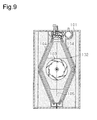
- A conventional example of such a two-way ceiling-mounted air conditioner is disclosed in Patent Document 1. This conventional example will now be described with reference to
Fig. 9 . As illustrated inFig. 9 , the air conditioner includes a rectangular-parallelepiped-shaped productmain body 101 having a rectangular shape in a planar view, and aheat exchanger 102 and aturbo fan 103 accommodated in the productmain body 101. Theheat exchanger 102 is typically made up of twobranch heat exchangers 104. The twobranch heat exchangers 104 are each located inside a side wall extending in a longitudinal direction of the productmain body 101. Theturbo fan 103 is located between the twobranch heat exchangers 104. Theturbo fan 103 is arranged substantially on acenter line 105 extending in the longitudinal direction of the productmain body 101. The twobranch heat exchangers 104 are bent at an obtuse angle at the middle of the productmain body 101 in the longitudinal direction in a planar view. The two obtuse-angle bends face each other across thecenter line 105. By bending theheat exchanger 102 in this manner, the total longitudinal lengths of thebranch heat exchangers 104 are increased, leading to an increase in heat exchange area of theheat exchanger 102. -
- Patent Document 1: Japanese Laid-Open Patent Publication No.
2003-287239 - There is still room for improvement, however, in the viewpoint of increasing the heat exchange area of the
heat exchanger 102. In other words, by changing the shapes of the twobranch heat exchangers 104 in the conventional air conditioner described above, the total longitudinal length of thebranch heat exchangers 104 can be further increased. To increase the heat exchange area by increasing the total longitudinal length of thebranch heat exchangers 104, it is important to design the shape and the structure of the branch heat exchangers such that productivity is not lowered. - Accordingly, it is an objective of the present invention to provide a two-way ceiling-mounted air conditioner including a heat exchanger having an increased heat exchange area, while maintaining the productivity.
- To achieve the foregoing objective and in accordance with one aspect of the present invention, a two-way ceiling-mounted air conditioner having a rectangular shape in a planar view is provided. The air conditioner includes a decorative panel and a rectangular-parallelepiped-shaped product main body. The decorative panel has indoor outlets configured to blow out temperature-controlled air into an interior of a room and an indoor inlet configured to draw in indoor air. The rectangular-parallelepiped-shaped product main body accommodates a mechanical fan and heat exchangers. The indoor outlets in the decorative panel are two in number and are formed along opposite long sides of the decorative panel. The mechanical fan is a centrifugal fan located in the product main body such that the mechanical fan has a rotation axis oriented in a vertical direction. The heat exchangers include two branch heat exchangers each located between one of the two indoor outlets and the mechanical fan such that the mechanical fan is located between the branch heat exchangers in a planar view. Each of the two branch heat exchangers is divided into a first end portion, an intermediate portion, and a second end portion in a longitudinal direction. At the first end portion, a refrigerant passage of the branch heat exchangers is connected to an external refrigerant pipe. At the second end portion, the refrigerant passage is turned. The intermediate portion is arranged in parallel with the indoor outlets. The first end portions and the second end portions are bent toward the mechanical fan, and the first end portions and the second end portions are bent at different angles in relation to the intermediate portion.
- In the configuration described above, the end portions of each of the branch heat exchangers are bent toward the mechanical fan. Thus, the total longitudinal length of the branch heat exchangers are increased in comparison with the conventional two-way ceiling-mounted air conditioner described above, leading to an increase in heat exchange area of the branch heat exchangers. Additionally, the bend angles of the end portions from the intermediate portion of each of the branch heat exchangers can be set to any angles in consideration of the dimensions of the product main body, the relationship between the length for a bender used for bending each of the branch heat exchangers to grip on and the bending lengths of the end portions of each of the branch heat exchangers, convenience of a pipe connection operation on the branch heat exchangers, and the like. Manufacturing disadvantages to the branch heat exchangers are averted in this manner.
- In the above described ceiling-mounted air conditioner, in relation to a longitudinal extension line of the intermediate portion of the corresponding branch heat exchanger, each first end portion is preferably bent at a bend angle not more than forty-five degrees.
- With the configuration described above, a brazing operation to connect flow dividing pipes onto the branch heat exchangers is facilitated. This is because the brazing operation is performed as described below. A brazing jig is used to temporarily assemble the two branch heat exchangers. Subsequently, brazing is performed on the pipes at one of the branch heat exchangers, and then brazing is performed on the pipes at the other branch heat exchanger. For brazing, it is necessary to position the branch heat exchangers as temporarily assembled so that the pipes to be brazed are oriented in the vertical direction. For example, to connect the flow dividing pipes at the first end portions of the two branch heat exchangers, it is necessary to reposition the branch heat exchangers, as temporarily assembled, together with the brazing jig so that the ends of the heat exchange tubes protruding at the first end portions are oriented in the vertical direction for each of the two branch heat exchangers. The first end portions each have a bend angle not more than forty-five degrees. The bend angle is defined in relation to an extension line of the intermediate portion of each of the branch heat exchangers in the longitudinal direction. This allows for a small angle change needed to reposition the brazing jig and thus facilitates the positioning operation. Additionally, the frequency at which one of the branch heat exchangers that has been connected to the pipes blocks the brazing operation on the other branch heat exchanger is reduced.
- In the above described ceiling-mounted air conditioner, in relation to the longitudinal extension line of the intermediate portion of the corresponding branch heat exchanger, the second end portion is preferably bent at a bend angle larger than the bend angle of the first end portion in relation to the longitudinal extension line of the intermediate portion.
- Through the configuration described above, the total longitudinal length of the branch heat exchangers can be increased. Because of this, the heat exchange areas of the branch heat exchangers can be increased, leading to an increase in heat exchange area of the heat exchanger.
- In the above described ceiling-mounted air conditioner, the first end portion of each of the branch heat exchangers is preferably connected to flow dividing pipes from a flow divider. In a planar view, the flow dividing pipes are preferably arranged in a substantially triangular region formed by an outermost straight line and two leader lines. The outermost straight line is formed by connecting outermost positions, in the longitudinal direction of the product main body, of the first end portions of the two branch heat exchangers. The two leader lines are each drawn from an edge of an air passing portion at the first end portion of the corresponding branch heat exchanger toward the opposite branch heat exchanger at a right angle to an air passing plane. Connection pipes to allow communication of the refrigerant passage are attached at more than one location on the first end portion of each of the branch heat exchangers in order to set the refrigerant passage in each of the branch heat exchangers to a predetermined length and in a predetermined arrangement. Thus, the outermost straight line for the heat exchanger is defined as a line connecting the outermost positions of these connection pipes in the two opposite branch heat exchangers.
- In the configuration described above, the flow dividing pipes from the flow divider are arranged in a triangular region formed by the outermost straight line and two extension lines, each of which is an extension of the end surface of the first end portion of each of the branch heat exchangers toward the opposite branch heat exchanger, in a planar view. Thus, the flow dividing pipes in a bundle do not block air flows passing through the branch heat exchangers. The flow dividing pipes from the flow divider are arranged so that, in a planar view, the pipes do not protrude outside the outermost straight line, which connects the outermost positions, in the longitudinal direction of the product main body, of the first end portions of the
branch heat exchangers 41. Thus, the air conditioner can be made compact. - In the above described ceiling-mounted air conditioner, the heat exchanger is preferably configured to allow a plurality of refrigerant outlet pipes from the two branch heat exchangers to be connected to one header.
- In the configuration described above, only a single header is needed instead of two headers, which would be normally needed for the two branch heat exchangers. Thus, the space needed for the header is minimized, thereby making the air conditioner compact.
- In the above described ceiling-mounted air conditioner, the mechanical fan is preferably located closer to the second end portion in the longitudinal direction of the product main body.
- Through the configuration described above, the space between the mechanical fan and the first end portions is made larger than the space between the mechanical fan and the second end portions. The larger space can be utilized effectively as a space for purposes such as connection and wiring between an electric component box and electric components. Electric components, such as a drain pump, are often connected to parts near the first end portions in particular. Thus, the larger space between the mechanical fan and the first end portions is advantageous for the connection of such electric components.
- In the above described ceiling-mounted air conditioner, the mechanical fan is preferably one of two mechanical fans, which are spaced in the longitudinal direction of the product main body, and a midpoint between the two mechanical fans is closer to the second end portion.
- In the configuration described above, the two mechanical fans are positioned closer to the second end portions in the product main body. Thus, the space between one of the two mechanical fans and the first end portions is made larger than the space between the other mechanical fan and the second end portions. The larger space can be utilized effectively as a space for purposes such as connection and wiring between an electric component box and electric components. This is particularly convenient for the connection of electric components, such as a drain pump, which is often arranged near the first end portions.
- The present invention allows the total longitudinal length of the branch heat exchangers to be increased in comparison with the conventional two-way ceiling-mounted air conditioner, leading to an increase in heat exchange area of the branch heat exchangers. Additionally, the end portions of each of the branch heat exchangers are bent to have different bend angles. Thus, the bend angles of the end portions from the intermediate portion can be set to any angles in consideration of the dimensions of the product main body, the relationship between the length for a bender for each of the branch heat exchangers to grip on and the bending lengths of the end portions of each of the branch heat exchangers, convenience of a pipe connection operation on the branch heat exchangers, and the like. Manufacturing disadvantages to the branch heat exchangers are averted in this manner.
-
-
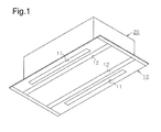
Fig. 1 is an external perspective view of a two-way ceiling-mounted air conditioner according to a first embodiment of the present invention; -
Fig. 2 is a cross-sectional plan view of the arrangement of devices in a product main body for the ceiling-mounted air conditioner illustrated inFig. 1 ; -
Fig. 3 is a cross-sectional side view of the arrangement of the devices in the ceiling-mounted air conditioner illustrated inFig. 1 ; -
Fig. 4 is an enlarged view of a heat exchanger at its end portion at which pipe connection is made in the ceiling-mounted air conditioner illustrated inFig. 1 ; -
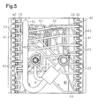
Fig. 5 is a diagram viewed along arrow V inFig. 4 ; -
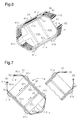
Fig. 6 is a perspective view of the heat exchanger as attached to a brazing jig; -
Fig. 7 is an explanatory diagram showing conditions for brazing at first end portions at which external refrigerant pipes are to be connected on the heat exchanger inFig. 6 ; -
Fig. 8 is a cross-sectional plan view of the arrangement of devices in a product main body for a two-way ceiling-mounted air conditioner according to a second embodiment of the invention; and -
Fig. 9 is a cross-sectional plan view of the arrangement of the devices in a product main body for a conventional two-way ceiling-mounted air conditioner. - A first embodiment of the present invention will now be described with reference to
Figs. 1 to 7 . - A two-way ceiling-mounted air conditioner according to the first embodiment constitutes an indoor unit for a split-type air conditioner.
- As illustrated in
Figs. 1 and3 , the two-way ceiling-mounted air conditioner has a rectangular shape in a planar view and includes adecorative panel 10 and a productmain body 20 coupled to an upper surface of thedecorative panel 10. Thedecorative panel 10 is attached to the bottom of the productmain body 20 and engaged with a ceiling material 1 (see -
Fig. 3 ). The productmain body 20 is attached to a building structural member (not shown) located in a space above the ceiling such that the productmain body 20 is suspended from the building structural member. Although the productmain body 20 and thedecorative panel 10 both have rectangular shapes in a planar view, the productmain body 20 has a somewhat smaller shape than thedecorative panel 10 as in the conventional air conditioner. - As illustrated in
Figs. 1 and3 , thedecorative panel 10 hasindoor outlets 11 along its two opposite long sides for blowing out temperature-controlled air into the interior of a room. Thedecorative panel 10 has elongatedindoor inlets 12 inside theindoor outlets 11 for drawing in the indoor air. - As illustrated in
Fig. 2 , the productmain body 20 includes a rectangular-parallel-piped box-shapedmain body casing 21, and amechanical fan 30 and aheat exchanger 40 accommodated in themain body casing 21. - The
mechanical fan 30 is a centrifugal fan, or more specifically a turbo fan, which is located in the productmain body 20 such that themechanical fan 30 has a rotation axis oriented in the vertical direction. As illustrated inFig. 2 , themechanical fan 30 is arranged such that, in a planar view, its rotation axis is on a center line CL extending in a longitudinal direction of the productmain body 20. Themechanical fan 30 is configured to be rotated clockwise, as marked by an arrow inFig. 2 , by adrive motor 32 attached to a top panel of themain body casing 21. As illustrated inFig. 3 , themechanical fan 30 has a lower surface defined by ashroud 33. Themechanical fan 30 is configured to draw in the air through an opening at the inner circumference side of theshroud 33 and blow out the air with increased pressure from the outer circumference of animpeller 31. Themechanical fan 30 includes abell mouth 34 in communication with the opening at the inner circumference side of theshroud 33. Thebell mouth 34 is configured to communicate through anair filter 22 located thereunder in the productmain body 20 with aninner space 13 between thedecorative panel 10 and theair filter 22 and with theindoor inlets 12. - The
heat exchanger 40 includes twobranch heat exchangers 41 each arranged between one of the twoindoor outlets 11 and themechanical fan 30 in a planar view. Thebranch heat exchangers 41 are located at the blow-out side of themechanical fan 30. - The
branch heat exchangers 41 are plate fin coils each including substantially U-shaped heat exchange tubes 42 (seeFig. 4 ) constituting a refrigerant passage andplate fins 43 attached to theheat exchange tubes 42. As is understandable fromFigs. 4 and5 , thebranch heat exchangers 41, each of which has two rows and sixteen stages, each have a seven-path refrigerant passage. - As illustrated in the cross-sectional plan view in
Fig. 2 , thebranch heat exchangers 41 each have anintermediate portion 41a arranged in parallel with theindoor outlets 11 and end portions bent toward themechanical fan 30, or in other words, toward the center line CL. In the description below, the end portion of each of thebranch heat exchangers 41 to which external refrigerant pipes are connected is referred to as afirst end portion 41 b, and the end portion that is opposite to thefirst end portion 41b and at which the refrigerant passage in thebranch heat exchanger 41 is turned is referred to as asecond end portion 41 c. As described above, thebranch heat exchangers 41 are each divided into thefirst end portion 41 b, which is bent toward themechanical fan 30, theintermediate portion 41a, and thesecond end portion 41c, which is bent toward themechanical fan 30. - The
first end portion 41b has a bend angle α in relation to an extension line of theintermediate portion 41 a in the longitudinal direction, and thesecond end portion 41c has a bend angle β in relation to an extension line of theintermediate portion 41a in the longitudinal direction. The bend angles α and β are preferably ninety degrees from the viewpoint of increasing the total longitudinal length of thebranch heat exchangers 41. The bend angles α and β are, however, set smaller than ninety degrees and differently from each other in order to satisfy required manufacturing conditions. - The bend angle α of the
first end portion 41 b of each of thebranch heat exchangers 41 is set to approximately forty-five degrees to facilitate a brazing operation on the pipes to theheat exchange tubes 42. Since theintermediate portion 41a is arranged substantially parallel with the center line CL, the bend angle α is the same as an angle from the center line CL to an extension line of thefirst end portion 41 b. - The bend angle β of the
second end portion 41c of each of thebranch heat exchangers 41 is set such that thesecond end portion 41c, which is bent, has a length greater than a required length for a bender used for bending thesecond end portion 41c to grip on and that thesecond end portion 41c forms a maximum angle from the longitudinal extension line of theintermediate portion 41 a. In this embodiment, the bend angle β of thesecond end portion 41c is approximately sixty degrees. The bend angle α of thefirst end portion 41 b, which is bent, is forty-five degrees as described above, and thus thefirst end portion 41 b sufficiently provides the required length for the bender to grip on. Since theintermediate portion 41 a is arranged substantially parallel with the center line CL, the bend angle β of thesecond end portion 41 c is the same as an angle from the center line CL to an extension line of thesecond end portion 41 c. - The product
main body 20 includes adrain pan 50 below theheat exchanger 40. - A
groove portion 51 is formed in a portion of thedrain pan 50 immediately below thebranch heat exchangers 41 to receive drain water from thebranch heat exchangers 41. Thedrain pan 50 also serves as a partition member to separate the blow-out side of themechanical fan 30 from the draw-in side thereof. The portion of thedrain pan 50 that serves as the partition member is referred to as apartition portion 52 herein. As illustrated inFig. 3 , thepartition portion 52 has around hole 53 formed therein at a position at which thebell mouth 34 is attached, such that theair filter 22 is in communication with thebell mouth 34. As illustrated inFigs. 2 and3 , thepartition portion 52 has elongatedsquare holes 54 formed therein below the space between each of thebranch heat exchangers 41 and a side wall so as to be in communication with theindoor outlets 11 in thedecorative panel 10. - A configuration in the proximity of the
first end portions 41 b of thebranch heat exchangers 41 will now be described. - As illustrated in
Fig. 2 , in the proximity of thefirst end portions 41 b of thebranch heat exchangers 41, devices are located, such as one that forms a refrigerant circuit external to theheat exchanger 40, one that is related to the connection of refrigerant pipes to an outdoor unit (not shown), and one that discharges the drain water. Specifically, aflow divider 61 to divide the flow of liquid refrigerant delivered from the outdoor unit, a plurality offlow dividing pipes 62 to deliver the refrigerant divided by theflow divider 61 to thebranch heat exchangers 41, a plurality ofrefrigerant outlet pipes 63 to allow the gas refrigerant to flow out from thebranch heat exchangers 41, and aheader 64 to collect therefrigerant outlet pipes 63 are located in the proximity of thefirst end portions 41 b of theheat exchanger 40. Additionally, a liquid refrigerant pipe joint 65 and a gas refrigerant pipe joint 66 for connecting connection pipes (not shown) to the outdoor unit are attached to a side panel of themain body casing 21. Furthermore, alevel sensor 67 to detect the level of the drain water collected in a collecting portion of thedrain pan 50, adrain pump 68 to pump out the drain water, a discharge pipe 68a to discharge the drain water pumped by thedrain pump 68, and a pipe joint 69 to connect the discharge pipe 68a to an external drain pipe are located therein. - Since the
branch heat exchangers 41 each have a seven-path refrigerant passage, sevenflow dividing pipes 62 from theflow divider 61 are connected to each of thebranch heat exchangers 41. In a planar view, theflow dividing pipes 62 are arranged in a substantially triangular region formed by twoleader lines branch heat exchangers 41 and an outermost straight line 45 formed by connecting the outermost positions, in the longitudinal direction of the productmain body 20, of thefirst end portions 41 b of thebranch heat exchangers 41. - Connection pipes to allow communication of the refrigerant passage are attached to more than one location on the
first end portion 41 b of each of thebranch heat exchangers 41 in order to set the refrigerant passage in each of thebranch heat exchangers 41 to a predetermined length and in a predetermined arrangement. Thus, the outermost straight line 45 for theheat exchanger 40 is defined as a line connecting the outermost positions of these connection pipes on the two oppositebranch heat exchangers 41. More specifically, substantially U-shapedbent pipes 48 to connect theheat exchange tubes 42 constituting the refrigerant passage are attached to more than one location on thefirst end portion 41b of each of thebranch heat exchangers 41 in order to set the refrigerant passage to the predetermined length and in the predetermined arrangement. The outermost straight line 45 for theheat exchanger 40 represents a line connecting points at the outermost positions of thebent pipes 48. - The two
leader lines first end portion 41b of each of thebranch heat exchangers 41 toward the oppositebranch heat exchanger 41 at a right angle to an air passing plane. In this embodiment, the edge of the air passing portion at thefirst end portion 41b corresponds to atube plate 41d located at thefirst end portion 41 b of each of thebranch heat exchangers 41. More specifically, the leader lines 46 and 47 each represent a line extending from the surface of each of thetube plates 41d. - Each of the
branch heat exchangers 41, which has a seven-path refrigerant passage, is configured to allow sevenrefrigerant outlet pipes 63 to extend therefrom. As illustrated inFig. 5 , therefrigerant outlet pipes 63 extending from thefirst end portion 41b of each of thebranch heat exchangers 41 are connected at ends thereof to the oneheader 64. In the present invention, theflow dividing pipes 62 and therefrigerant outlet pipes 63 are the pipes that are external to thebranch heat exchangers 41 and connected to the refrigerant passage in each of thebranch heat exchangers 41. - The
mechanical fan 30 is located at a position in the productmain body 20 closer to thesecond end portions 41 c and away from thefirst end portions 41b of thebranch heat exchangers 41. Because of this, the space between themechanical fan 30 and thefirst end portions 41 b of thebranch heat exchangers 41 is larger than the space between themechanical fan 30 and thesecond end portions 41c of thebranch heat exchangers 41. Anelectric component box 71 is arranged in this larger space below thepartition portion 52. The utilization of this space allows electric components, such as thedrain pump 68 and thelevel sensor 67 described above, located in the proximity of thefirst end portions 41b of thebranch heat exchangers 41 to be connected to electric components located in anelectric component box 71. - Operation of the two-way ceiling-mounted air conditioner with the configuration described above will be described below.
- Air conditioning operation of the ceiling-mounted air conditioner according to the embodiment will now be described.
- The air conditioning operation of the ceiling-mounted air conditioner is performed by operating a compressor mounted in the non-depicted outdoor unit and the
mechanical fan 30 housed in the productmain body 20. In the air conditioning operation, the indoor air flows as marked with hollow arrows inFig. 3 . Specifically, the indoor air is drawn in from theindoor inlets 12 through theinner space 13 above thedecorative panel 10 and through theair filter 22 to be drawn in by themechanical fan 30. The air is then blown out from the outer circumference of themechanical fan 30 to be divided into the two oppositebranch heat exchangers 41. The temperature of the air is controlled by passing through thebranch heat exchangers 41. The temperature-controlled air is blown out through the elongated square holes 54 formed in the side portions of thedrain pan 50 and then from theindoor outlets 11 into the interior of the room. - For a cooling operation performed as the air conditioning operation, the liquid refrigerant delivered from the outdoor unit (not shown) through the liquid refrigerant pipe joint 65 flows as marked by solid arrows in
Fig. 4 to be divided by theflow divider 61 evenly to theflow dividing pipes 62. The liquid refrigerant divided by theflow divider 61 flows through theflow dividing pipes 62 into the refrigerant passages of thebranch heat exchangers 41. While passing through the refrigerant passages, the liquid refrigerant is vaporized through heat exchange with the indoor air to turn to a gas refrigerant. The gas refrigerant passes through therefrigerant outlet pipes 63 to be collected in theheader 64 and then is returned through the gas refrigerant pipe joint 66 to the outdoor unit. For a heating operation performed by the air conditioner configured as a heat pump system, the refrigerant is allowed to flow in the reverse direction, a detailed description of which will be omitted here. - The heat exchanger offers improved performance in such air conditioning operations over the conventional example described above. This is due to the
intermediate portions 41 a of thebranch heat exchangers 41 arranged in parallel with theindoor outlets 11 and thefirst end portions 41b and thesecond end portions 41c of thebranch heat exchangers 41 bent toward themechanical fan 30. They allow the total longitudinal length of thebranch heat exchangers 41 mountable in the productmain body 20 to be increased longer than those in the conventional example, thereby increasing the heat exchange area of theheat exchanger 40. - A pipe connection operation performed on the
heat exchanger 40 with the configuration described above will now be described. The pipe connection operation on theheat exchanger 40 mainly involves the brazing operation of theflow dividing pipes 62 and therefrigerant outlet pipes 63 onto theheat exchange tubes 42 at thefirst end portions 41 b of thebranch heat exchangers 41. - As illustrated in
Fig. 6 , abrazing jig 80 is used to temporarily assemble the twobranch heat exchangers 41 into positions identical with those as assembled in the productmain body 20. - The
brazing jig 80 includes anouter member 81 to support theheat exchanger 40 at four locations from outside and aninner member 82 to press theintermediate portion 41a of each of thebranch heat exchangers 41 against theouter member 81. As illustrated inFig. 6 , theouter member 81 includes a plane supporting wall 81 a to support the bottom of theheat exchanger 40,side supporting walls 81b to support theintermediate portions 41a of the twobranch heat exchangers 41 at two opposite locations, and a curved endportion supporting wall 81c to support thesecond end portions 41c of the twobranch heat exchangers 41 simultaneously. Theside supporting walls 81b and the endportion supporting wall 81c are coupled to the plane supporting wall 81a. Theinner member 82 includespressing walls 82a to press theintermediate portions 41 a against theside supporting walls 81b of theouter member 81 from inside and urgingmembers 82b to urge thepressing walls 82a outward. - The two
branch heat exchangers 41 are temporarily assembled using thebrazing jig 80 in a manner described below. Thesecond end portions 41c of thebranch heat exchangers 41 are coupled with each other. The coupledbranch heat exchangers 41 are then fitted in theouter member 81 of thebrazing jig 80 as illustrated inFig. 6 so that thebranch heat exchangers 41 form a shape identical with that as housed in the productmain body 20. The urgingmembers 82b of theinner member 82 are then operated to allow thepressing walls 82a to press theintermediate portions 41 a of thebranch heat exchangers 41 against theside supporting walls 81b of theouter member 81. As a result, theintermediate portions 41a of thebranch heat exchangers 41 are each held between one of theside supporting walls 81b of theouter member 81 and one of thepressing walls 82a of theinner member 82. Theheat exchanger 40 is temporarily assembled using thebrazing jig 80 in this manner. - The end portions of the
heat exchanger 40 as temporarily assembled are then brazed. To facilitate the brazing in a reliable manner, the brazing is performed on one of thebranch heat exchangers 41 and then on the otherbranch heat exchanger 41. - For example, as illustrated in a section of the diagram to the left in
Fig. 7 , at the left one of thebranch heat exchangers 41, thetube plate 41 d of itsfirst end portion 41 b is retained horizontally so that the axes of theheat exchange tubes 42 to be brazed are oriented in the vertical direction. This facilitates reliable brazing of theflow dividing pipes 62 and therefrigerant outlet pipes 63 onto theheat exchange tubes 42 of thefirst end portion 41b of the left one of thebranch heat exchangers 41. When the brazing on the left one of thebranch heat exchangers 41 is finished, theheat exchanger 40 as temporarily assembled is rotated together with thebrazing jig 80 as illustrated in a section of the diagram to the right inFig. 7 , so that the brazing is performed on the right one of thebranch heat exchangers 41 in a similar manner to the left one of thebranch heat exchangers 41. - It is convenient to perform brazing in the
brazing jig 80 also on other pipes and devices that are around thefirst end portions 41b of thebranch heat exchangers 41 and are to be brazed before the assembly into the productmain body 20. For example, to braze therefrigerant outlet pipes 63 of thebranch heat exchangers 41 onto theheader 64, theheat exchanger 40 as temporarily assembled is rotated together with thebrazing jig 80 so that the axes of therefrigerant outlet pipes 63 at brazing locations are oriented in the vertical direction, in a manner similar to that described above. This facilitates reliable brazing of therefrigerant outlet pipes 63 onto theheader 64. - The ceiling-mounted air conditioner according to the embodiment with the configuration described above is capable of achieving advantages as described below.
- (1) The total longitudinal length of the
branch heat exchangers 41 can be increased in comparison with the conventional two-way ceiling-mounted air conditioner described above, leading to an increase in heat exchange area of thebranch heat exchangers 41. - (2) The bend angle α of the
first end portion 41 b and the bend angle β of thesecond end portion 41c of each of thebranch heat exchangers 41 are different from each other. Thus, the bend angles α and β of the end portions can be set to any angles in consideration of the dimensions of the productmain body 20, the relationship between the length for a bender for each of thebranch heat exchangers 41 to grip on and the bending lengths of the end portions of each of thebranch heat exchangers 41, convenience of the pipe connection operation on thebranch heat exchangers 41, and the like. Manufacturing disadvantages to the branch heat exchangers are averted in this manner. - (3) The bend angle α of the
first end portion 41 b of each of thebranch heat exchangers 41 is not more than forty-five degrees. This facilitates positioning theheat exchanger 40 as temporarily assembled so that the axes of theheat exchange tubes 42 to be brazed are oriented in the vertical direction. This facilitates the brazing operation to connect theflow dividing pipes 62 onto thebranch heat exchangers 41. - (4) The bend angle β of the
second end portion 41c of each of thebranch heat exchangers 41 is set to an angle larger than the bend angle α of thefirst end portion 41 b. This is advantageous for maximization of the total longitudinal length of thebranch heat exchangers 41. By increasing the total longitudinal length of thebranch heat exchangers 41, the heat exchange area of thebranch heat exchangers 41 can be increased, thereby increasing the heat exchange area of theheat exchanger 40. - (5) The
flow dividing pipes 62 from theflow divider 61 are arranged in a triangular region formed by the outermost straight line 45 and the twoleader lines main body 20, of thefirst end portions 41 b of thebranch heat exchangers 41. The twoleader lines first end portion 41b of each of thebranch heat exchangers 41 toward the oppositebranch heat exchanger 41 at the right angle to the air passing plane. Thus, theflow dividing pipes 62 in a bundle do not block the air flow passing through thebranch heat exchangers 41. - (6) The plurality of flow dividing pipes 62 (fourteen of them to be specific) from the
flow divider 61 is arranged such that the pipes do not protrude outside the outermost straight line 45 in the longitudinal direction in a planar view. Thus, the air conditioner can be made compact. - (7) Since all of the plurality of refrigerant outlet pipes 63 (seven of them from each of the
branch heat exchangers 41 to be specific) from thebranch heat exchangers 41 are connected to the oneheader 64, only asingle header 64 is needed instead of two headers that would be normally needed for the twobranch heat exchangers 41. Thus, the space needed for theheader 64 can be minimized, thereby making the air conditioner compact. - (8) The
mechanical fan 30 is located at position in the productmain body 20 closer to thesecond end portions 41c of thebranch heat exchangers 41. Because of this, the space between themechanical fan 30 and thefirst end portions 41b can be made larger than the space between themechanical fan 30 and thesecond end portions 41c. Thus, the larger space can be utilized effectively as a space for purposes such as connection and wiring between theelectric component box 71 and electric components. This space is particularly convenient for the connection of electric components, such as thedrain pump 68 and thelevel sensor 67, which are often located near thefirst end portions 41b of thebranch heat exchangers 41. - A second embodiment will now be described with reference to
Fig. 8 . In a two-way ceiling-mounted air conditioner according to the second embodiment, adecorative panel 10 and a productmain body 20 have longitudinal dimensions larger than those in the first embodiment, so that twomechanical fans 30 are provided for improved performance. Other configurations are identical to those in the first embodiment. The two-way ceiling-mounted air conditioner according to the second embodiment will be described with emphasis on differences from the first embodiment. Identical components to those in the first embodiment are indicated with identical reference numerals, and their description will be omitted or simplified. - In the ceiling-mounted air conditioner according to the second embodiment, the dimensions of a
main body casing 21, thedecorative panel 10, and adrain pan 50 are changed to increase the longitudinal dimension of the productmain body 20 for improved performance as described above. Additionally,branch heat exchangers 41 have longitudinal dimensions larger than those in the first embodiment to correspond to the longitudinal dimensions of the productmain body 20. More specifically,intermediate portions 41a of thebranch heat exchangers 41 have dimensions larger than those in the first embodiment.First end portions 41 b and second end portions, which are bent, have dimensions identical with those in the first embodiment. - In the ceiling-mounted air conditioner according to the second embodiment, the two
mechanical fans 30 are located in the productmain body 20 with a longitudinal distance therebetween to improve the performance. Apartition wall 35 is located between the twomechanical fans 30 to partition a space at the blow-out side of themechanical fans 30. The midpoint between the twomechanical fans 30 is positioned closer to thesecond end portions 41c. - Because of the configuration described above, the ceiling-mounted air conditioner according to the second embodiment achieves advantages described below in addition to the advantages in the first embodiment described in (1) to (7) above.
- (9) The two
mechanical fans 30 are arranged with their midpoint positioned closer to thesecond end portions 41c in the productmain body 20. Thus, the space between one of the twomechanical fans 30 and thefirst end portions 41 b is larger than the space between the othermechanical fan 30 and thesecond end portions 41c. Because of this, the space of thefirst end portions 41b can be utilized effectively as a space for purposes such as connection and wiring between anelectric component box 71 and electric components. This space is particularly convenient for the connection of electric components, such as adrain pump 68 and alevel sensor 67, which are often located near thefirst end portions 41b of thebranch heat exchangers 41. - The two-way ceiling-mounted air conditioner according to the invention is not limited to the embodiments described above, and modifications as described below are also viable. The modifications as described below may also be combined as appropriate.
- · Although the plate fin coils each including the substantially U-shaped
heat exchange tubes 42 and the plate fins attached to theheat exchange tubes 42 are described as a specific example of theheat exchangers 40 in the first and second embodiments described above, other types of heat exchanger for air may be used. For example, other types of heat exchanger include a micro-channel heat exchanger including micro-channels constituting a refrigerant passage. - · The bend angle α of the
first end portions 41b in the first and second embodiments are most preferably forty-five degrees from the viewpoint of maximizing the total longitudinal length of thebranch heat exchangers 41 and facilitating the brazing operation on pipes at thefirst end portions 41 b. The bend angle α, however, may be another angle. The bend angle α is preferably not more than forty-five degrees from the viewpoint of improving the workability of brazing on the pipes. - · The bend angle β of the
second end portions 41c in the first and second embodiments is preferably as close to ninety degrees as possible as long as thesecond end portions 41c each provide a length for a bender to grip on. Thus, the bend angle β in the embodiments described above is not limited to sixty degrees. - · In the first and second embodiments described above, the mechanical fan(s) 30 is/are positioned at a position in the product
main body 20 closer to thesecond end portions 41c. When an electric component box is located between the mechanical fan(s) 30 and thefirst end portions 41 b, such positioning of the mechanical fan(s) 30 in the productmain body 20 is preferable since an increase in internal air flow resistance due to wiring or the like for the electric component box does not occur. The invention, however, is not limited thereto. - · In the first and second embodiments described above, the
flow dividing pipes 62 from theflow divider 61 are arranged in a triangular region formed by the outermost straight line 45 and the twoleader lines main body 20, of thefirst end portions 41b of thebranch heat exchangers 41. The twoleader lines first end portion 41 b of each of thebranch heat exchangers 41 toward the oppositebranch heat exchanger 41 at the right angle to the air passing plane. The invention, however, is not limited thereto. If theflow dividing pipes 62 are arranged in the triangle as described above, the internal air flow resistance due to theflow dividing pipes 62 is prevented from increasing. - · In the first and second embodiments described above, the
indoor inlets 12 are formed into elongated shapes similar to those of theindoor outlets 11 and positioned inside theindoor outlets 11 at the lower surface of thedecorative panel 10. Theindoor inlets 12, however, may extend over a substantially entire area inside theindoor outlets 11. - · The
decorative panel 10 in the first and second embodiments described above has a lower surface formed into a plane. The invention, however, is not limited thereto. For example, the short sides of thedecorative panel 10 may have middle portions protruding downward. These protruding portions may form a plane surface thereon extending all along the long side of thedecorative panel 10. Inclined surfaces may be formed at both sides of the plane surface and extend all along the long sides of the plane surface. Theindoor inlet 12 may extend over the substantially entire area of the plane surface in the middle, andindoor outlets 11 may be provided in the inclined surfaces formed at both sides of the plane surface.
Claims (7)
- A two-way ceiling-mounted air conditioner having a rectangular shape in a planar view, the air conditioner comprising:a decorative panel having indoor outlets configured to blow out temperature-controlled air into an interior of a room and an indoor inlet configured to draw in indoor air; anda rectangular-parallelepiped-shaped product main body accommodating a mechanical fan and heat exchangers, the air conditioner being characterized in thatthe indoor outlets in the decorative panel are two in number and are formed along opposite long sides of the decorative panel,the mechanical fan is a centrifugal fan located in the product main body such that the mechanical fan has a rotation axis oriented in a vertical direction,the heat exchangers include two branch heat exchangers each located between one of the two indoor outlets and the mechanical fan such that the mechanical fan is located between the branch heat exchangers in a planar view,each of the two branch heat exchangers is divided into a first end portion, an intermediate portion, and a second end portion in a longitudinal direction, wherein
at the first end portion, a refrigerant passage of the branch heat exchangers is connected to an external refrigerant pipe,
at the second end portion, the refrigerant passage is turned, and
the intermediate portion is arranged in parallel with the indoor outlets, andthe first end portions and the second end portions are bent toward the mechanical fan, and the first end portions and the second end portions are bent at different angles in relation to the intermediate portion. - The ceiling-mounted air conditioner according to claim 1, characterized in that, in relation to a longitudinal extension line of the intermediate portion of the corresponding branch heat exchanger, each first end portion is bent at a bend angle not more than forty-five degrees.
- The ceiling-mounted air conditioner according to claim 2, characterized in that, in relation to the longitudinal extension line of the intermediate portion of the corresponding branch heat exchanger, the second end portion is bent at a bend angle larger than the bend angle of the first end portion in relation to the longitudinal extension line of the intermediate portion.
- The ceiling-mounted air conditioner according to any one of claims 1 to 3, characterized in that
the first end portion of each of the branch heat exchangers is connected to flow dividing pipes from a flow divider, and
in a planar view, the flow dividing pipes are arranged in a substantially triangular region formed by an outermost straight line and two leader lines, wherein the outermost straight line is formed by connecting outermost positions, in the longitudinal direction of the product main body, of the first end portions of the two branch heat exchangers, the two leader lines are each drawn from an edge of an air passing portion at the first end portion of the corresponding branch heat exchanger toward the opposite branch heat exchanger at a right angle to an air passing plane. - The ceiling-mounted air conditioner according to any one of claims 1 to 4, characterized in that the heat exchanger is configured to allow a plurality of refrigerant outlet pipes from the two branch heat exchangers to be connected to one header.
- The ceiling-mounted air conditioner according to any one of claims 1 to 5, characterized in that the mechanical fan is located closer to the second end portion in the longitudinal direction of the product main body.
- The ceiling-mounted air conditioner according to any one of claims 1 to 5, characterized in that the mechanical fan is one of two mechanical fans, which are spaced in the longitudinal direction of the product main body, and a midpoint between the two mechanical fans is closer to the second end portion.
Applications Claiming Priority (2)
| Application Number | Priority Date | Filing Date | Title |
|---|---|---|---|
| JP2012061004A JP5494705B2 (en) | 2012-03-16 | 2012-03-16 | Two-way blowout ceiling air conditioner |
| PCT/JP2013/055283 WO2013136992A1 (en) | 2012-03-16 | 2013-02-28 | Bidirectional-blow-out, ceiling-embedded air conditioner |
Publications (3)
| Publication Number | Publication Date |
|---|---|
| EP2827071A1 true EP2827071A1 (en) | 2015-01-21 |
| EP2827071A4 EP2827071A4 (en) | 2015-12-09 |
| EP2827071B1 EP2827071B1 (en) | 2018-06-06 |
Family
ID=49160908
Family Applications (1)
| Application Number | Title | Priority Date | Filing Date |
|---|---|---|---|
| EP13760702.4A Active EP2827071B1 (en) | 2012-03-16 | 2013-02-28 | Bidirectional-blow-out, ceiling-embedded air conditioner |
Country Status (6)
| Country | Link |
|---|---|
| EP (1) | EP2827071B1 (en) |
| JP (1) | JP5494705B2 (en) |
| CN (1) | CN104169652B (en) |
| ES (1) | ES2676711T3 (en) |
| TR (1) | TR201809517T4 (en) |
| WO (1) | WO2013136992A1 (en) |
Cited By (1)
| Publication number | Priority date | Publication date | Assignee | Title |
|---|---|---|---|---|
| WO2016170456A1 (en) * | 2015-04-20 | 2016-10-27 | Gandini Jacques | Diffusion unit for the air-conditioning of an indoor environment |
Families Citing this family (9)
| Publication number | Priority date | Publication date | Assignee | Title |
|---|---|---|---|---|
| JP6458984B2 (en) * | 2014-10-10 | 2019-01-30 | 株式会社富士通ゼネラル | Embedded ceiling air conditioner |
| CN104896588B (en) * | 2015-05-26 | 2018-03-30 | 广东美的制冷设备有限公司 | air conditioner indoor unit |
| CN107588476B (en) * | 2016-07-08 | 2024-01-26 | 珠海格力电器股份有限公司 | Heat exchange mechanism and air conditioner outdoor unit with same |
| CN107588475B (en) * | 2016-07-08 | 2023-10-27 | 珠海格力电器股份有限公司 | Air conditioner outdoor unit |
| CN106765577B (en) * | 2017-01-03 | 2022-08-26 | 珠海格力电器股份有限公司 | Fresh air assembly capable of discharging air annularly and air conditioner |
| JP6477784B2 (en) * | 2017-05-24 | 2019-03-06 | ダイキン工業株式会社 | Air conditioner indoor unit |
| JP6409907B1 (en) * | 2017-05-24 | 2018-10-24 | ダイキン工業株式会社 | Air conditioner indoor unit |
| JP7011187B2 (en) * | 2019-11-14 | 2022-02-10 | ダイキン工業株式会社 | Refrigerant shunt and air conditioner |
| US12305886B2 (en) * | 2020-12-14 | 2025-05-20 | Rheem Manufacturing Company | Heating systems with unhoused centrifugal fan and wraparound heat exchanger |
Family Cites Families (7)
| Publication number | Priority date | Publication date | Assignee | Title |
|---|---|---|---|---|
| JPS60159531A (en) * | 1984-01-27 | 1985-08-21 | Sanyo Electric Co Ltd | Heat exchanging unit |
| JPH11148711A (en) * | 1997-11-14 | 1999-06-02 | Mitsubishi Heavy Ind Ltd | Ceiling embedded type air-conditioner |
| JP2000046360A (en) * | 1998-07-29 | 2000-02-18 | Hitachi Ltd | Ceiling-mounted indoor unit |
| JP4724939B2 (en) * | 2001-03-30 | 2011-07-13 | ダイキン工業株式会社 | Air conditioner |
| JP3758592B2 (en) * | 2002-03-28 | 2006-03-22 | 三菱電機株式会社 | Recessed ceiling air conditioner |
| JP4141368B2 (en) * | 2003-10-10 | 2008-08-27 | 三洋電機株式会社 | Embedded ceiling air conditioner |
| CN102460026B (en) * | 2009-06-19 | 2014-05-07 | 大金工业株式会社 | Ceiling embedded air conditioner |
-
2012
- 2012-03-16 JP JP2012061004A patent/JP5494705B2/en active Active
-
2013
- 2013-02-28 ES ES13760702.4T patent/ES2676711T3/en active Active
- 2013-02-28 TR TR2018/09517T patent/TR201809517T4/en unknown
- 2013-02-28 EP EP13760702.4A patent/EP2827071B1/en active Active
- 2013-02-28 CN CN201380013481.3A patent/CN104169652B/en active Active
- 2013-02-28 WO PCT/JP2013/055283 patent/WO2013136992A1/en not_active Ceased
Cited By (1)
| Publication number | Priority date | Publication date | Assignee | Title |
|---|---|---|---|---|
| WO2016170456A1 (en) * | 2015-04-20 | 2016-10-27 | Gandini Jacques | Diffusion unit for the air-conditioning of an indoor environment |
Also Published As
| Publication number | Publication date |
|---|---|
| JP5494705B2 (en) | 2014-05-21 |
| ES2676711T3 (en) | 2018-07-24 |
| CN104169652A (en) | 2014-11-26 |
| EP2827071B1 (en) | 2018-06-06 |
| WO2013136992A1 (en) | 2013-09-19 |
| EP2827071A4 (en) | 2015-12-09 |
| TR201809517T4 (en) | 2018-07-23 |
| JP2013194961A (en) | 2013-09-30 |
| CN104169652B (en) | 2017-05-03 |
Similar Documents
| Publication | Publication Date | Title |
|---|---|---|
| EP2827071B1 (en) | Bidirectional-blow-out, ceiling-embedded air conditioner | |
| EP2208946B1 (en) | Indoor unit for air conditioner | |
| EP3037773A1 (en) | Heat exchanger, air conditioner, refrigeration cycle device, and method for producing heat exchanger | |
| US10465924B2 (en) | Heat exchanger | |
| EP3650798A1 (en) | Heat exchanger | |
| WO2019239445A1 (en) | Refrigerant distributor, heat exchanger, and air conditioner | |
| EP2933570B1 (en) | Outdoor unit for air conditioner | |
| JP4818935B2 (en) | Air conditioner outdoor unit | |
| EP3252385B1 (en) | Air conditioner | |
| JP5338883B2 (en) | Heat source unit | |
| JP2008261552A (en) | Heat source unit | |
| CN103574774B (en) | Air conditioner | |
| CN116724209B (en) | Heat exchanger | |
| JP6661781B2 (en) | Refrigeration cycle device | |
| JP2000146218A (en) | Indoor unit of air conditioner | |
| JP2003097820A (en) | Air conditioner | |
| JP3170545B2 (en) | Air conditioner | |
| CN209689086U (en) | Heat exchanger assembly and air-conditioner outdoor unit with it | |
| JP5997115B2 (en) | Air conditioner | |
| JP3304536B2 (en) | Air conditioner | |
| JP6486718B2 (en) | Heat exchanger | |
| CN110462296A (en) | air conditioner indoor unit | |
| EP3903058B1 (en) | Fin using in a heat exchanger, heat exchanger having the fins, and refrigeration cycle device having the heat exchanger | |
| JP2006337018A (en) | Ceiling buried type air conditioner, and manufacturing method of heat exchanger | |
| JP2001201170A (en) | Method of manufacturing indoor unit, and indoor unit and air conditioner |
Legal Events
| Date | Code | Title | Description |
|---|---|---|---|
| PUAI | Public reference made under article 153(3) epc to a published international application that has entered the european phase |
Free format text: ORIGINAL CODE: 0009012 |
|
| 17P | Request for examination filed |
Effective date: 20140902 |
|
| AK | Designated contracting states |
Kind code of ref document: A1 Designated state(s): AL AT BE BG CH CY CZ DE DK EE ES FI FR GB GR HR HU IE IS IT LI LT LU LV MC MK MT NL NO PL PT RO RS SE SI SK SM TR |
|
| AX | Request for extension of the european patent |
Extension state: BA ME |
|
| DAX | Request for extension of the european patent (deleted) | ||
| RA4 | Supplementary search report drawn up and despatched (corrected) |
Effective date: 20151105 |
|
| RIC1 | Information provided on ipc code assigned before grant |
Ipc: F24F 13/072 20060101ALI20151030BHEP Ipc: F24F 1/00 20110101AFI20151030BHEP |
|
| GRAP | Despatch of communication of intention to grant a patent |
Free format text: ORIGINAL CODE: EPIDOSNIGR1 |
|
| STAA | Information on the status of an ep patent application or granted ep patent |
Free format text: STATUS: GRANT OF PATENT IS INTENDED |
|
| INTG | Intention to grant announced |
Effective date: 20180117 |
|
| GRAS | Grant fee paid |
Free format text: ORIGINAL CODE: EPIDOSNIGR3 |
|
| GRAA | (expected) grant |
Free format text: ORIGINAL CODE: 0009210 |
|
| STAA | Information on the status of an ep patent application or granted ep patent |
Free format text: STATUS: THE PATENT HAS BEEN GRANTED |
|
| AK | Designated contracting states |
Kind code of ref document: B1 Designated state(s): AL AT BE BG CH CY CZ DE DK EE ES FI FR GB GR HR HU IE IS IT LI LT LU LV MC MK MT NL NO PL PT RO RS SE SI SK SM TR |
|
| REG | Reference to a national code |
Ref country code: GB Ref legal event code: FG4D |
|
| REG | Reference to a national code |
Ref country code: CH Ref legal event code: EP Ref country code: AT Ref legal event code: REF Ref document number: 1006524 Country of ref document: AT Kind code of ref document: T Effective date: 20180615 |
|
| REG | Reference to a national code |
Ref country code: IE Ref legal event code: FG4D |
|
| REG | Reference to a national code |
Ref country code: DE Ref legal event code: R096 Ref document number: 602013038577 Country of ref document: DE |
|
| REG | Reference to a national code |
Ref country code: ES Ref legal event code: FG2A Ref document number: 2676711 Country of ref document: ES Kind code of ref document: T3 Effective date: 20180724 |
|
| REG | Reference to a national code |
Ref country code: NL Ref legal event code: MP Effective date: 20180606 |
|
| REG | Reference to a national code |
Ref country code: LT Ref legal event code: MG4D |
|
| PG25 | Lapsed in a contracting state [announced via postgrant information from national office to epo] |
Ref country code: SE Free format text: LAPSE BECAUSE OF FAILURE TO SUBMIT A TRANSLATION OF THE DESCRIPTION OR TO PAY THE FEE WITHIN THE PRESCRIBED TIME-LIMIT Effective date: 20180606 Ref country code: LT Free format text: LAPSE BECAUSE OF FAILURE TO SUBMIT A TRANSLATION OF THE DESCRIPTION OR TO PAY THE FEE WITHIN THE PRESCRIBED TIME-LIMIT Effective date: 20180606 Ref country code: NO Free format text: LAPSE BECAUSE OF FAILURE TO SUBMIT A TRANSLATION OF THE DESCRIPTION OR TO PAY THE FEE WITHIN THE PRESCRIBED TIME-LIMIT Effective date: 20180906 Ref country code: FI Free format text: LAPSE BECAUSE OF FAILURE TO SUBMIT A TRANSLATION OF THE DESCRIPTION OR TO PAY THE FEE WITHIN THE PRESCRIBED TIME-LIMIT Effective date: 20180606 Ref country code: BG Free format text: LAPSE BECAUSE OF FAILURE TO SUBMIT A TRANSLATION OF THE DESCRIPTION OR TO PAY THE FEE WITHIN THE PRESCRIBED TIME-LIMIT Effective date: 20180906 Ref country code: CY Free format text: LAPSE BECAUSE OF FAILURE TO SUBMIT A TRANSLATION OF THE DESCRIPTION OR TO PAY THE FEE WITHIN THE PRESCRIBED TIME-LIMIT Effective date: 20180606 |
|
| PG25 | Lapsed in a contracting state [announced via postgrant information from national office to epo] |
Ref country code: HR Free format text: LAPSE BECAUSE OF FAILURE TO SUBMIT A TRANSLATION OF THE DESCRIPTION OR TO PAY THE FEE WITHIN THE PRESCRIBED TIME-LIMIT Effective date: 20180606 Ref country code: RS Free format text: LAPSE BECAUSE OF FAILURE TO SUBMIT A TRANSLATION OF THE DESCRIPTION OR TO PAY THE FEE WITHIN THE PRESCRIBED TIME-LIMIT Effective date: 20180606 Ref country code: GR Free format text: LAPSE BECAUSE OF FAILURE TO SUBMIT A TRANSLATION OF THE DESCRIPTION OR TO PAY THE FEE WITHIN THE PRESCRIBED TIME-LIMIT Effective date: 20180907 Ref country code: LV Free format text: LAPSE BECAUSE OF FAILURE TO SUBMIT A TRANSLATION OF THE DESCRIPTION OR TO PAY THE FEE WITHIN THE PRESCRIBED TIME-LIMIT Effective date: 20180606 |
|
| REG | Reference to a national code |
Ref country code: AT Ref legal event code: MK05 Ref document number: 1006524 Country of ref document: AT Kind code of ref document: T Effective date: 20180606 |
|
| PG25 | Lapsed in a contracting state [announced via postgrant information from national office to epo] |
Ref country code: NL Free format text: LAPSE BECAUSE OF FAILURE TO SUBMIT A TRANSLATION OF THE DESCRIPTION OR TO PAY THE FEE WITHIN THE PRESCRIBED TIME-LIMIT Effective date: 20180606 |
|
| PG25 | Lapsed in a contracting state [announced via postgrant information from national office to epo] |
Ref country code: AT Free format text: LAPSE BECAUSE OF FAILURE TO SUBMIT A TRANSLATION OF THE DESCRIPTION OR TO PAY THE FEE WITHIN THE PRESCRIBED TIME-LIMIT Effective date: 20180606 Ref country code: IS Free format text: LAPSE BECAUSE OF FAILURE TO SUBMIT A TRANSLATION OF THE DESCRIPTION OR TO PAY THE FEE WITHIN THE PRESCRIBED TIME-LIMIT Effective date: 20181006 Ref country code: EE Free format text: LAPSE BECAUSE OF FAILURE TO SUBMIT A TRANSLATION OF THE DESCRIPTION OR TO PAY THE FEE WITHIN THE PRESCRIBED TIME-LIMIT Effective date: 20180606 Ref country code: RO Free format text: LAPSE BECAUSE OF FAILURE TO SUBMIT A TRANSLATION OF THE DESCRIPTION OR TO PAY THE FEE WITHIN THE PRESCRIBED TIME-LIMIT Effective date: 20180606 Ref country code: SK Free format text: LAPSE BECAUSE OF FAILURE TO SUBMIT A TRANSLATION OF THE DESCRIPTION OR TO PAY THE FEE WITHIN THE PRESCRIBED TIME-LIMIT Effective date: 20180606 Ref country code: CZ Free format text: LAPSE BECAUSE OF FAILURE TO SUBMIT A TRANSLATION OF THE DESCRIPTION OR TO PAY THE FEE WITHIN THE PRESCRIBED TIME-LIMIT Effective date: 20180606 Ref country code: PL Free format text: LAPSE BECAUSE OF FAILURE TO SUBMIT A TRANSLATION OF THE DESCRIPTION OR TO PAY THE FEE WITHIN THE PRESCRIBED TIME-LIMIT Effective date: 20180606 |
|
| PG25 | Lapsed in a contracting state [announced via postgrant information from national office to epo] |
Ref country code: SM Free format text: LAPSE BECAUSE OF FAILURE TO SUBMIT A TRANSLATION OF THE DESCRIPTION OR TO PAY THE FEE WITHIN THE PRESCRIBED TIME-LIMIT Effective date: 20180606 |
|
| REG | Reference to a national code |
Ref country code: DE Ref legal event code: R097 Ref document number: 602013038577 Country of ref document: DE |
|
| PLBE | No opposition filed within time limit |
Free format text: ORIGINAL CODE: 0009261 |
|
| STAA | Information on the status of an ep patent application or granted ep patent |
Free format text: STATUS: NO OPPOSITION FILED WITHIN TIME LIMIT |
|
| 26N | No opposition filed |
Effective date: 20190307 |
|
| PG25 | Lapsed in a contracting state [announced via postgrant information from national office to epo] |
Ref country code: DK Free format text: LAPSE BECAUSE OF FAILURE TO SUBMIT A TRANSLATION OF THE DESCRIPTION OR TO PAY THE FEE WITHIN THE PRESCRIBED TIME-LIMIT Effective date: 20180606 Ref country code: SI Free format text: LAPSE BECAUSE OF FAILURE TO SUBMIT A TRANSLATION OF THE DESCRIPTION OR TO PAY THE FEE WITHIN THE PRESCRIBED TIME-LIMIT Effective date: 20180606 |
|
| REG | Reference to a national code |
Ref country code: CH Ref legal event code: PL |
|
| PG25 | Lapsed in a contracting state [announced via postgrant information from national office to epo] |
Ref country code: MC Free format text: LAPSE BECAUSE OF FAILURE TO SUBMIT A TRANSLATION OF THE DESCRIPTION OR TO PAY THE FEE WITHIN THE PRESCRIBED TIME-LIMIT Effective date: 20180606 Ref country code: LU Free format text: LAPSE BECAUSE OF NON-PAYMENT OF DUE FEES Effective date: 20190228 |
|
| REG | Reference to a national code |
Ref country code: BE Ref legal event code: MM Effective date: 20190228 |
|
| REG | Reference to a national code |
Ref country code: IE Ref legal event code: MM4A |
|
| PG25 | Lapsed in a contracting state [announced via postgrant information from national office to epo] |
Ref country code: AL Free format text: LAPSE BECAUSE OF FAILURE TO SUBMIT A TRANSLATION OF THE DESCRIPTION OR TO PAY THE FEE WITHIN THE PRESCRIBED TIME-LIMIT Effective date: 20180606 |
|
| PG25 | Lapsed in a contracting state [announced via postgrant information from national office to epo] |
Ref country code: LI Free format text: LAPSE BECAUSE OF NON-PAYMENT OF DUE FEES Effective date: 20190228 Ref country code: CH Free format text: LAPSE BECAUSE OF NON-PAYMENT OF DUE FEES Effective date: 20190228 |
|
| PG25 | Lapsed in a contracting state [announced via postgrant information from national office to epo] |
Ref country code: IE Free format text: LAPSE BECAUSE OF NON-PAYMENT OF DUE FEES Effective date: 20190228 |
|
| PG25 | Lapsed in a contracting state [announced via postgrant information from national office to epo] |
Ref country code: BE Free format text: LAPSE BECAUSE OF NON-PAYMENT OF DUE FEES Effective date: 20190228 |
|
| PG25 | Lapsed in a contracting state [announced via postgrant information from national office to epo] |
Ref country code: MT Free format text: LAPSE BECAUSE OF NON-PAYMENT OF DUE FEES Effective date: 20190228 Ref country code: PT Free format text: LAPSE BECAUSE OF FAILURE TO SUBMIT A TRANSLATION OF THE DESCRIPTION OR TO PAY THE FEE WITHIN THE PRESCRIBED TIME-LIMIT Effective date: 20181008 |
|
| PG25 | Lapsed in a contracting state [announced via postgrant information from national office to epo] |
Ref country code: HU Free format text: LAPSE BECAUSE OF FAILURE TO SUBMIT A TRANSLATION OF THE DESCRIPTION OR TO PAY THE FEE WITHIN THE PRESCRIBED TIME-LIMIT; INVALID AB INITIO Effective date: 20130228 |
|
| PG25 | Lapsed in a contracting state [announced via postgrant information from national office to epo] |
Ref country code: MK Free format text: LAPSE BECAUSE OF FAILURE TO SUBMIT A TRANSLATION OF THE DESCRIPTION OR TO PAY THE FEE WITHIN THE PRESCRIBED TIME-LIMIT Effective date: 20180606 |
|
| P01 | Opt-out of the competence of the unified patent court (upc) registered |
Effective date: 20230525 |
|
| PGFP | Annual fee paid to national office [announced via postgrant information from national office to epo] |
Ref country code: FR Payment date: 20251231 Year of fee payment: 14 |
|
| PGFP | Annual fee paid to national office [announced via postgrant information from national office to epo] |
Ref country code: GB Payment date: 20260106 Year of fee payment: 14 |
|
| PGFP | Annual fee paid to national office [announced via postgrant information from national office to epo] |
Ref country code: ES Payment date: 20260304 Year of fee payment: 14 |
|
| PGFP | Annual fee paid to national office [announced via postgrant information from national office to epo] |
Ref country code: DE Payment date: 20260102 Year of fee payment: 14 |
|
| PGFP | Annual fee paid to national office [announced via postgrant information from national office to epo] |
Ref country code: IT Payment date: 20260122 Year of fee payment: 14 |
|
| PGFP | Annual fee paid to national office [announced via postgrant information from national office to epo] |
Ref country code: TR Payment date: 20260225 Year of fee payment: 14 |