EP2827004B1 - Mehrstufiger Ejektor - Google Patents
Mehrstufiger Ejektor Download PDFInfo
- Publication number
- EP2827004B1 EP2827004B1 EP14175046.3A EP14175046A EP2827004B1 EP 2827004 B1 EP2827004 B1 EP 2827004B1 EP 14175046 A EP14175046 A EP 14175046A EP 2827004 B1 EP2827004 B1 EP 2827004B1
- Authority
- EP
- European Patent Office
- Prior art keywords
- nozzle
- ejector
- sleeve
- nozzles
- string
- Prior art date
- Legal status (The legal status is an assumption and is not a legal conclusion. Google has not performed a legal analysis and makes no representation as to the accuracy of the status listed.)
- Active
Links
Images



Classifications
-
- F—MECHANICAL ENGINEERING; LIGHTING; HEATING; WEAPONS; BLASTING
- F04—POSITIVE - DISPLACEMENT MACHINES FOR LIQUIDS; PUMPS FOR LIQUIDS OR ELASTIC FLUIDS
- F04F—PUMPING OF FLUID BY DIRECT CONTACT OF ANOTHER FLUID OR BY USING INERTIA OF FLUID TO BE PUMPED; SIPHONS
- F04F5/00—Jet pumps, i.e. devices in which flow is induced by pressure drop caused by velocity of another fluid flow
- F04F5/44—Component parts, details, or accessories not provided for in, or of interest apart from, groups F04F5/02 - F04F5/42
- F04F5/46—Arrangements of nozzles
- F04F5/467—Arrangements of nozzles with a plurality of nozzles arranged in series
-
- F—MECHANICAL ENGINEERING; LIGHTING; HEATING; WEAPONS; BLASTING
- F04—POSITIVE - DISPLACEMENT MACHINES FOR LIQUIDS; PUMPS FOR LIQUIDS OR ELASTIC FLUIDS
- F04F—PUMPING OF FLUID BY DIRECT CONTACT OF ANOTHER FLUID OR BY USING INERTIA OF FLUID TO BE PUMPED; SIPHONS
- F04F5/00—Jet pumps, i.e. devices in which flow is induced by pressure drop caused by velocity of another fluid flow
- F04F5/14—Jet pumps, i.e. devices in which flow is induced by pressure drop caused by velocity of another fluid flow the inducing fluid being elastic fluid
- F04F5/16—Jet pumps, i.e. devices in which flow is induced by pressure drop caused by velocity of another fluid flow the inducing fluid being elastic fluid displacing elastic fluids
- F04F5/20—Jet pumps, i.e. devices in which flow is induced by pressure drop caused by velocity of another fluid flow the inducing fluid being elastic fluid displacing elastic fluids for evacuating
- F04F5/22—Jet pumps, i.e. devices in which flow is induced by pressure drop caused by velocity of another fluid flow the inducing fluid being elastic fluid displacing elastic fluids for evacuating of multi-stage type
Definitions
- the invention relates to a multi-stage ejector, comprising a nozzle arrangement, which has at least three nozzles arranged in series in the direction of a longitudinal axis, wherein the nozzles are adapted to be flowed through by a fluid, wherein between each of the nozzles in each case a fluid gap wherein at least two of the at least three nozzles are integrally connected to a nozzle train, and wherein the nozzles are at least partially disposed in a sleeve and the nozzles and the sleeve are fixed to each other releasably.
- Such a multi-stage ejector is marketed by the company SMC under the type designation multi-stage ejector "ZL 212".
- a multi-stage ejector of the type mentioned is used to generate a vacuum or negative pressure. With the generated negative pressure, for example, objects can be lifted.
- the ejector is connected to a corresponding lifting device, wherein the negative pressure generated by the ejector acts on a suction pad, with which the object is raised.
- an ejector is based on the law of Bernoulli, according to which in a flow the static pressure decreases with increasing flow velocity.
- the ejector is operated with a fluid, in particular compressed air, as the driving medium, which flows through the nozzle arrangement at high speed.
- a fluid in particular compressed air
- This reduced static pressure is used to draw from a space surrounding the ejector medium, in lifting applications, air, via one or more suction ports in the sleeve of the ejector which communicate with the fluid gaps between the individual nozzles.
- the ejector is used in use in an ejector housing, wherein the ejector housing has a bore whose inner diameter is adapted to the outer diameter of the sleeve, so that the sleeve is received without play in the bore.
- the Ejektorgepuruse has connections for the supply of fluid as a driving medium and connections for suction of suction medium.
- the aforementioned known ejector has a total of four nozzles, seen in the flow direction of the fluid, a drive nozzle and three receiver nozzles, wherein all the nozzles are arranged in series in the direction of a longitudinal axis.
- the three receiver nozzles of this known ejector are integrally connected with each other to form a nozzle train.
- the nozzle string is received in a sleeve, wherein the nozzle string and the sleeve are fixed to each other releasably.
- the nozzle train and the sleeve are connected by a frictional engagement, which is effected by seals which are arranged on the outside of the nozzle train and seal against the inner wall of the sleeve.
- Another multi-stage ejector is off EP 1 064 464 B3 known.
- the individual nozzles are each provided at the end with coupling means, so that the individual nozzles can be connected directly to one another to form a nozzle body.
- a sleeve does not have this known ejector.
- a multi-stage ejector in which the nozzle assembly comprises a plurality of individual nozzles, which are initially held individually in an inner frame.
- the inner frame is inserted into an outer sleeve and by means of a locking structure, the inner frame and the outer frame are fixed against rotation against each other.
- the disadvantage of this known ejector consists in its many parts, because it has individual nozzles, an inner frame and an outer sleeve, so that the structure of this known ejector is very complex. Along with this, the assembly of this known ejector is time-consuming. Another ejector is out of the DE 4491977 known.
- the invention is therefore the object of developing a multi-stage ejector of the type mentioned in that the ejector has only a few parts and with respect to its assembly and its installation and removal in or out of an ejector is easy to handle, so that he increased without Wait for effort.
- this object is achieved in terms of the above-mentioned multi-stage ejector in that the nozzle train and the sleeve are fixed axially to each other by a form-fitting locking mechanism.
- the ejector according to the invention is based on the concept that, in order to save individual parts, at least two nozzles of the nozzle arrangement are connected to one another to form a one-piece nozzle strand. This not only leads to a lower cost in the production of the ejector, but also improves its ease of handling, since at least some of the nozzles do not need to be assembled in advance.
- the nozzle train and the sleeve are fixed axially to one another by a locking mechanism acting in a form-locking manner.
- the positive connection between the nozzle train and the sleeve increases the ease of handling, especially when removing the ejector from an ejector, since the axial positive engagement between the nozzle train and the sleeve ensures that the nozzle strand is not prematurely separated from the sleeve and the sleeve when pulling out the ejector not undesirably gets stuck in the bore of the Ejektorgephinuses, but can be completely pulled out together with the nozzle train.
- the nozzle string can be easily separated from the sleeve by disconnecting the positive fit from the sleeve.
- the ejector according to the invention can except the nozzle train and the sleeve, a nozzle, for example, as seen in the flow direction first nozzle (motive nozzle) have as a single nozzle, and optionally check valves, as will be described later.
- a nozzle for example, as seen in the flow direction first nozzle (motive nozzle) have as a single nozzle, and optionally check valves, as will be described later.
- the ejector according to the invention comes out with very few individual parts, which makes its construction less complicated and its handling is particularly friendly.
- the locking mechanism sets the nozzle train and the sleeve relative to each other also secured against rotation together.
- the locking mechanism is designed as a plug-in rotary connection, in particular as a bayonet connection.
- a plug-in rotary connection is particularly advantageous in terms of ease of handling, since such a connection can be made quickly with simple steps and can also be solved quickly.
- a plug-in rotary connection with a short plug-in distance and short rotational travel which may be smaller than 45 ° in the direction of rotation about the longitudinal axis, is sufficient.
- a plug-in rotary connection, in particular a bayonet connection ensures a secure axially acting positive locking, so that an axially acting force when removing the ejector from the Ejektorgepuruse does not lead to an undesirable premature separation of the nozzle string from the sleeve.
- the locking mechanism is preferably designed as a latching connection.
- the plug-in rotary connection in particular bayonet connection, as a latching connection by, for example, at the end the rotational path of the nozzle strand locked with the sleeve.
- This has the advantage that when assembling the nozzle string and the sleeve by the engagement of the user a haptic or acoustic signal is conveyed, indicating that the sleeve and the nozzle string are now fixed in the correct position relative to each other securely together.
- the latching connection can ensure that the nozzle train and the sleeve are held in the assembled state relative to each other against rotation, wherein the expended for releasing the latching connection force depends on the nature of the latching connection. If a high force is required to release the locking connection, the locking connection may be provided with an actuating member such as a push button, so that the latching connection can be solved only after its actuation.
- the fixing mechanism is arranged on the nozzle train at a distance from one end of the nozzle train, so that the nozzle train projects beyond the sleeve.
- the nozzle string thus projects beyond the end of the sleeve, which has the advantage that when removing the ejector from the Ejektorgeophuse the end of the nozzle string can be grasped by hand to pull the ejector as a whole from the Ejektorgeophuse, and for disassembly the ejector in the sleeve and nozzle string can be gripped with one hand, the easily accessible end of the nozzle string and with the other hand, the sleeve.
- the locking mechanism has at least one radially projecting nose on the nozzle string and a in Direction of the longitudinal axis extending recess, followed by a circumferentially extending around the longitudinal axis recess adjoins the sleeve.
- This configuration is a structurally particularly simple embodiment of the fixing mechanism as a plug-and-turn connection, in particular as a bayonet connection.
- the extending in the longitudinal direction of the longitudinal axis recess on the sleeve may be formed on the sleeve inside as a groove, and in the circumferential direction around the Longitudinal axis adjoining recess on the sleeve may be formed as an opening in the wall of the sleeve, which in addition to the bayonet connection a catch connection is created by the radially projecting nose engages the nozzle strand during rotation of the nozzle strand relative to the sleeve in the opening.
- the nozzle train has a flange which comes to lie against a front side of the sleeve when the nozzle strand is connected to the sleeve.
- the preferably formed as a radial annular flange flange on the nozzle strand thus acts as a stop which abuts the sleeve against the end face of the sleeve upon insertion of the nozzle strand and thus causes a well-defined axial relative position between the nozzle train and the sleeve. This also increases the ease of handling of the ejector, since the flange prevents too deep insertion of the nozzle strand into the sleeve.
- the sleeve has at least one radial opening, wherein between the nozzle train and the sleeve at least one non-return valve for closing and releasing the opening is removably disposed on the nozzle train, wherein the non-return valve on the nozzle train against rotation about the longitudinal axis and / or secured against displacement in the direction of the longitudinal axis relative to the nozzle train.
- check valves are known per se in ejectors.
- the removability of the at least one non-return valve improves the ease of maintenance of the ejector, since the non-return valve can be easily replaced when worn against a new non-return valve. Since the removability of the check valve this is arranged more or less loosely between the sleeve and the nozzle train, the measure of twisting and / or displacement assurance relative to the nozzle train has the advantage that the axial position and the rotational position of the check valve is well-defined and remains.
- this measure has the advantage that the axial insertion of the nozzle strand into the sleeve and the rotation of the nozzle strand relative to the sleeve Check valve does not lose its predetermined position and orientation.
- the at least one non-return valve on a teilumfbaren ring wherein the nozzle train has a seat for rotationally secured and / or axially secured receiving the ring.
- the non-return flap for closing and releasing the at least one opening in the sleeve may have a slotted ring band extending circumferentially about the longitudinal axis, which is integrally connected to the ring via an axial web which may be made thin.
- the ring may also be made thin in the axial direction.
- the seat on the nozzle string for receiving the ring can be formed by two axially spaced apart flanges on the outside of the nozzle body, wherein between the two flanges can project a radial nose on both sides abut the free ends of the partially circumferential ring to prevent rotation of the check valve.
- the at least three nozzles have a drive nozzle and at least two receiver nozzles, wherein the at least two receiver nozzles form the one-piece nozzle train.
- the aforementioned measure has the advantage that the motive nozzle can be formed as a replacement part.
- the blowing nozzle can be made of metal, while the one-piece receiver nozzle strand can be manufactured as a low-cost plastic part.
- the nozzle arrangement has at least four nozzles, which have a drive nozzle and at least three receiver nozzles, wherein the at least three receiver nozzles form the one-piece nozzle train.
- a multi-stage ejector provided with the general reference numeral 10 is shown. Further details of the ejector 10 go from the Fig. 3 to 8 out.
- the ejector 10 is used to generate a negative pressure or vacuum.
- the ejector 10 has a nozzle arrangement 12 with a total of four nozzles 14, 16, 18 and 20 in the embodiment shown.
- the nozzles 14, 16, 18 and 20 are arranged in series in the direction of a longitudinal axis 21.
- the nozzles 14, 16, 18 and 20 are designed to be flowed through by a fluid, in particular compressed air.
- a fluid in particular compressed air.
- the fluid flow is indicated on the input side with an arrow 22 and on the output side with arrows 24.
- the nozzle 14 forms the motive nozzle, and the nozzles 16, 18 and 20 form the receiver nozzles.
- the nozzle 14 has according to Fig. 1a ) a fluid passageway 26, the nozzle 16 a fluid passageway 28, the nozzle 18 a fluid passageway 30 and the nozzle 20 a fluid passageway 32 on.
- a passage cross section of the fluid passage 28 is greater than a passage cross section of the fluid passage 26, and the fluid passage 30 has a larger passage cross section than the fluid passage 28 and the fluid passage 32 has a larger passage cross section than the fluid passageway 30.
- the nozzles 16, 18, 20 are integrally connected to a nozzle string 34 with each other.
- the nozzle 14 is designed as a single nozzle.
- nozzle assembly 12 is shown with the nozzle train 34 and the nozzle 14 in isolation.
- the nozzle train 34 is a total of one piece made of plastic.
- the nozzle 14 is made of aluminum, for example.
- a fluid gap namely a fluid gap 36 between the nozzle 14 and the nozzle 16, a fluid gap 38 between the nozzle 16 and the nozzle 18 and a fluid gap 40 between the nozzle 18 and the nozzle 20th
- the webs 42 and 44 are distributed around the longitudinal axis 21 around and ensure a sufficiently large opening cross-section of the fluid gaps 38 and 40th
- the nozzle 14 and the nozzle train 34 with the nozzles 16, 18 and 20 are at least partially received in a total of one-piece sleeve.
- the sleeve 46 has a first end 48 in the region of the nozzle 14 and a second end 50 in the region of the nozzle 20.
- the nozzle 20 projects beyond the second end 50 of the sleeve 46.
- the nozzle string 34 and the sleeve 46 are according to Fig. 1a ) and b) as well FIGS. 2a ) and b) axially fixed by a form-fitting locking mechanism 52, that is, in the direction of the longitudinal axis 21, and in the rotational direction about the longitudinal axis 21 to each other.
- the locking mechanism will also be described below with reference to Fig. 8 described.
- the locking mechanism 52 is disposed on the sleeve 46 at the end, in the region of the second end 50, while the fixing mechanism 52 is disposed on the nozzle string 34 at a distance from one end 54 of the nozzle string 34.
- the locking mechanism 52 is designed as a plug-in rotary connection, in particular as a bayonet connection.
- the fixing mechanism 52 has two radially projecting lugs 56 and 58 (see Fig. 1 b) on the nozzle train 34, which extend around the longitudinal axis 21 teilumfnaturelich.
- the lugs 56 and 58 are offset by 180 ° about the longitudinal axis 21 to each other.
- the lobes 56 and 58 have radial surfaces 57 and 59 which are curved, but with an eccentricity with respect to the longitudinal axis 21. In this way, the surfaces 57 and 59 act as chamfers when closing the locking mechanism 52 when the nozzle string 34 relative to the sleeve 46 is turned.
- the locking mechanism 52 further includes two extending in the direction of the longitudinal axis 21 recesses 60 and 62, which are formed as grooves on the inside of the sleeve 46.
- the recesses 60 and 62 have an extent in the circumferential direction about the longitudinal axis 21, which is slightly larger than the circumferential extent of the lugs 56 and 58 on the nozzle train 34.
- the axial Clearrekkung the recesses 60 and 62 is for the recess 60 in Fig. 1a ) indicated by broken lines.
- the recesses 60 and 62 are open to the extreme end of the end 50 of the sleeve 46.
- a further recess 64 adjoins the axial recess 60 in the circumferential direction about the longitudinal axis 21, and a further recess 66 adjoins the axial recess 62 in the same direction of rotation.
- the recesses 64 and 66 are formed as compared to the second end 50 recessed radial openings in the sleeve 46. In the fixed state of the nozzle string 34 and the sleeve 46, the radial lugs 56 and 58 engage in the recesses 64 and 66 a.
- the radial lugs 56 and 58 have a slightly larger radial extent than corresponds to the inner diameter of the sleeve 46 in the region of the second end 50, so that the radial lugs 56 and 58 can engage in the recesses 64 and 66.
- the locking mechanism 52 is thus not only designed as a plug-in rotary connection in the form of a bayonet connection, but also as a latching connection.
- the nozzle train 34 can thus be fixed to the sleeve 46 axially and in the direction of rotation about the longitudinal axis 21 by means of the fixing mechanism 52.
- the nozzle train 34 has at a distance from its end 54 on a flange 68 which is formed here as a fully circumferential radially projecting annular flange which comes to lie against a front side 70 of the sleeve 46 when fixing the nozzle string 34 and the sleeve 46.
- the flange 68 thus limits the depth of insertion of the nozzle string 34 into the sleeve 46.
- Fig. 1a ) and b) as well Fig. 2a ) and b) and Fig. 8 show the ejector 10 in a state in which the nozzle string 34 and the sleeve 46 by means of Festlegemechanismus 52 are fixed to each other.
- the nozzle train 34 is first rotated counterclockwise about the longitudinal axis 21 relative to the sleeve 46, whereby the radial lugs 56 and 58 with the recesses 64 and 66 are disengaged.
- the radial lugs 56 and 58 enter into the axial recesses 60 and 62 a.
- the required rotational travel of the nozzle train 34 relative to the sleeve 46 is about 40 °, but at least less than 45 °.
- the nozzle string 34 may be fully withdrawn from the sleeve 46, as in FIG Fig. 3 indicated by an arrow 72.
- the assembling of the ejector 10, that is, the connection of the nozzle string 34 with the sleeve 46 is done in reverse order, that is, the nozzle string 34 is first inserted into the sleeve 46, in a relative rotational position to the sleeve 46, in which the radial lugs 56 and 58 can dive into the axial recesses 60 and 62.
- the nozzle string 34 is clockwise ( Fig. 8 ) is rotated relative to the sleeve 46 until the radial lugs 56 and 58 engage with the recesses 64 and 66.
- the beveled surfaces 57 and 59 of the lobes 56 and 58 reduce the force of rotation and ensure a clearly noticeable engagement of the lugs 56 and 58 in the recesses 64 and 66 by the leading end of the lugs when rotating the nozzle string 34 to close the locking mechanism 52 56 and 58 has a smaller radial extent than the trailing end.
- the sleeve 46 further includes a plurality of, here six, radial openings 74a, 74b, 76a, 76b, 78a and 78b, which allow communicating the interior of the sleeve 46 with its exterior space.
- check valves 80, 82 and 84 are provided, of which the check valves 82 and 84 are connected to the nozzle train 34, while the non-return valve 80 is connected to the nozzle 14.
- the check valves 82 and 84 are loosely connected to the nozzle string 34, and the check valve 80 is loosely connected to the nozzle 14.
- the check valves 80, 82 and 84 can thus be removed from the nozzle 14 and from the nozzle train 34 for the purpose of replacement in case of wear.
- Fig. 7 shows the check valve 84 by way of example in isolation. The same description applies to the other two check valves 80 and 82.
- the check valve 84 which is made entirely of an elastomer or rubber, a slotted ring band 86, which forms two wings 88 and 90 due to its extensive interruption.
- the wing 88 serves to close the opening 78b and the wing 90 to close the opening 78a of the sleeve 46th
- the ring band 86 is connected in one piece via an axial web 92 with a partially circumferential or interrupted ring 94.
- check valve 84 check valves 80, 82 and 84 on nozzle 14 and on nozzle train 34, respectively, are prevented from rotating about longitudinal axis 21 and against displacement in longitudinal axis 21 relative to nozzle 14 and Nozzle string 34 secured.
- a seat 95 is formed, which is formed by two radial flanges 96 and 98, which are formed as a full-circumference annular flanges, and whose distance corresponds to the thickness of the ring 94. Between the two flanges 96 and 98 of the ring 84 is used in attaching the check valve 84 to the nozzle train 34. Between the flanges 96 and 98, the check valve 84 is thus secured axially against displacement.
- the slot 95 further includes a radial lug 100 between the two flanges 96 and 98 which defines the rotational position of the check valve 84 relative to the nozzle string 34 with respect to the longitudinal axis 21 and via the securement mechanism 52 relative to the openings 78a and 78b and the check valve 84 also prevents rotation about the longitudinal axis 21 relative to the nozzle string 34.
- the check valve 84 is attached to the nozzle train 34 so that a slotted area 102 of the ring 94 comes to rest at the level of the nose 100, so that the two ends 104 and 106 of the ring 94 are supported on both sides of the nose 100.
- the check valves 82 and 84 are first attached to the nozzle string 34 in the predetermined axial position and rotational position. Subsequently, the nozzle train 34 is inserted into the sleeve 46, which can not be axially displaced relative to the nozzle train 34 by the axial securing of the check valves 82 and 84 on the nozzle train 34 during insertion of the nozzle train 34 in the sleeve 46. During the subsequent rotation of the nozzle strand 34 relative to the sleeve 46 for closing the fixing mechanism 52 prevents the rotation of the check valves 82 and 84 on the nozzle train 34 an undesirable rotation of the check valves 82 and 84 relative to the nozzle train 34th
- the nozzles 14, 16, 18 and 20 also have seats or seats 108, 110, 112 and 114 for receiving in each case a ring seal (omitted in the drawing) to the nozzles 14, 16, 18 and 20 in sections against the sleeve 46th seal.
- the ejector 10 is used in use in an ejector housing, not shown, having a correspondingly adapted to the outer diameter of the sleeve 46 bore. If the ejector 10 has to be removed from the ejector housing for maintenance purposes, the previously described locking mechanism 52, via which the nozzle train 34 and the sleeve 46 are fixed to one another, prevents the nozzle train 34 from the sleeve 46 when an axial tensile force is exerted on the nozzle train 34 releases prematurely and only the nozzle train 34 is pulled out of the Ejektorgephinuse while the sleeve 46 gets stuck in the Ejektorgephinuse.
- the locking mechanism 52 allows easy disassembly of the ejector 10 in the nozzle train 34 and the sleeve 46 and also easy assembly of these parts. Also, when inserting the nozzle string 34 into the sleeve 46, the position and orientation of the check valves 82 and 84 relative to the nozzle string 34 does not change, as previously described.
Landscapes
- Engineering & Computer Science (AREA)
- Physics & Mathematics (AREA)
- Fluid Mechanics (AREA)
- Mechanical Engineering (AREA)
- General Engineering & Computer Science (AREA)
- Jet Pumps And Other Pumps (AREA)
- Catching Or Destruction (AREA)
Description
- Die Erfindung betrifft einen mehrstufigen Ejektor, mit einer Düsenanordnung, die zumindest drei Düsen aufweist, die in Richtung einer Längsachse in Reihe angeordnet sind, wobei die Düsen dazu ausgelegt sind, von einem Fluid durchströmt zu werden, wobei zwischen benachbarten der Düsen jeweils ein Fluidspalt vorhanden ist, wobei zumindest zwei der zumindest drei Düsen einstückig zu einem Düsenstrang miteinander verbunden sind, und wobei die Düsen zumindest teilweise in einer Hülse angeordnet und die Düsen und die Hülse aneinander lösbar festgelegt sind.
- Ein derartiger mehrstufiger Ejektor wird von der Firma SMC unter der Typenbezeichnung Mehrstufenejektor- "ZL 212" vertrieben.
- Ein mehrstufiger Ejektor der eingangs genannten Art wird zum Erzeugen eines Vakuums bzw. Unterdrucks verwendet. Mit dem erzeugten Unterdruck können beispielsweise Gegenstände gehoben werden. Zu diesem Zweck wird der Ejektor mit einer entsprechenden Hebevorrichtung verbunden, wobei der vom Ejektor erzeugte Unterdruck auf einen Sauggreifer wirkt, mit dem der Gegenstand angehoben wird.
- Allgemein basiert das Funktionsprinzip eines Ejektors auf dem Gesetz von Bernoulli, wonach in einer Strömung der statische Druck mit zunehmender Strömungsgeschwindigkeit absinkt. Der Ejektor wird mit einem Fluid, insbesondere Druckluft, als Treibmedium betrieben, das mit hoher Geschwindigkeit durch die Düsenanordnung strömt. An den Fluidspalten zwischen den einzelnen Düsen entsteht dabei ein statischer Unterdruck. Dieser verringerte statische Druck wird benutzt, um aus einem den Ejektor umgebenden Raum Medium, bei Hebeanwendungen Luft, über eine oder mehrere Saugöffnungen in der Hülse des Ejektors anzusaugen, die mit den Fluidspalten zwischen den einzelnen Düsen kommunizieren.
- Der Ejektor ist im Gebrauch in ein Ejektorgehäuse eingesetzt, wobei das Ejektorgehäuse eine Bohrung aufweist, deren Innendurchmesser an den Außendurchmesser der Hülse angepasst ist, so dass die Hülse spielfrei in der Bohrung aufgenommen ist. Das Ejektorgehäuse weist Anschlüsse für die Zufuhr von Fluid als Treibmedium und Anschlüsse zum Ansaugen von Saugmedium auf.
- Der eingangs genannte bekannte Ejektor weist insgesamt vier Düsen auf, in Strömungsrichtung des Fluids gesehen eine Treibdüse sowie drei Empfängerdüsen, wobei alle Düsen in Richtung einer Längsachse in Reihe angeordnet sind. Die drei Empfängerdüsen dieses bekannten Ejektors sind einstückig zu einem Düsenstrang miteinander verbunden. Der Düsenstrang ist in einer Hülse aufgenommen, wobei der Düsenstrang und die Hülse aneinander lösbar festgelegt sind.
- Bei dem bekannten Ejektor sind der Düsenstrang und die Hülse über einen Reibschluss, der durch außenseitig an dem Düsenstrang angeordnete Dichtungen, die an der Innenwand der Hülse dichtend anliegen, bewirkt wird.
- Nun ist es von Zeit zu Zeit erforderlich, den Ejektor aus dem Ejektorgehäuse zu Wartungszwecken auszubauen, wobei hierzu der Ejektor aus der Bohrung des Ejektorgehäuses herausgezogen werden muss. Da bei dem bekannten Ejektor der Düsenstrang lediglich durch Reibschluss an der Hülse festgelegt ist, kann es beim Herausziehen des Ejektors aus dem Ejektorgehäuse vorkommen, dass nur der Düsenstrang aus der Hülse herausgezogen wird, während die Hülse in dem Ejektorgehäuse stecken bleibt, die dann nur unter erhöhtem Manipulationsaufwand aus dem Ejektorgehäuse entfernt werden kann. Es wäre zwar möglich, den Reibschluss zwischen dem Düsenstrang und der Hülse so zu erhöhen, dass sich beim Herausziehen des Ejektors aus dem Gehäuse der Düsenstrang von der Hülse nicht vorzeitig trennt, jedoch führt dies zu einer erschwerten Handhabung des Ejektors bei dessen Zerlegung in Düsenstrang und Hülse, da das Trennen des Düsenstrangs von der Hülse dann mit erhöhtem Kraftaufwand verbunden ist. Die Handhabungs- und Wartungsfreundlichkeit des bekannten Ejektors ist somit nachteilig reduziert.
- Ein weiterer mehrstufiger Ejektor ist aus
EP 1 064 464 B3 bekannt. Bei diesem bekannten Ejektor sind die einzelnen Düsen jeweils endseitig mit Kopplungsmitteln versehen, so dass die einzelnen Düsen unmittelbar miteinander zu einem Düsenkörper verbunden werden können. Eine Hülse weist dieser bekannte Ejektor nicht auf. - Der Nachteil dieses bekannten Ejektors besteht darin, dass der Ejektor aus vielen einzelnen Teilen zusammengesetzt werden muss, da alle Düsen als Einzeldüsen vorliegen. Des Weiteren ergibt sich wie bei dem zuvor genannten bekannten Ejektor der Nachteil, dass bei dem Herausziehen des Ejektors aus dem Ejektorgehäuse sich die Düsen vorzeitig voneinander trennen und einzelne Düsen dann im Gehäuse stecken bleiben. Somit sind auch bei diesem bekannten Ejektor die Handhabung und die Wartungsfreundlichkeit nicht zufriedenstellend.
- Aus
EP 1 969 234 B1 ist ein mehrstufiger Ejektor bekannt, bei dem die Düsenanordnung mehrere einzelne Düsen aufweist, die zunächst in einem inneren Rahmen einzeln gehalten sind. Der innere Rahmen wird in eine äußere Hülse eingesetzt und mittels einer Verriegelungsstruktur werden der innere Rahmen und der äußere Rahmen drehgesichert aneinander festgelegt. Der Nachteil dieses bekannten Ejektors besteht in seiner Vielteiligkeit, weil er einzelne Düsen, einen inneren Rahmen und eine äußere Hülse aufweist, so dass der Aufbau dieses bekannten Ejektors sehr aufwändig ist. Damit einhergehend ist auch der Zusammenbau dieses bekannten Ejektors zeitaufwändig. Ein weiterer Ejektor ist aus derDE 4491977 bekannt. - Der Erfindung liegt daher die Aufgabe zugrunde, einen mehrstufigen Ejektor der eingangs genannten Art dahingehend weiterzubilden, dass der Ejektor nur wenige Teile aufweist und bezüglich seines Zusammenbaus und seines Ein- und Ausbaus in bzw. aus einem Ejektorgehäuse handhabungsfreundlich ist, so dass er sich ohne erhöhten Aufwand warten lässt.
- Erfindungsgemäß wird diese Aufgabe hinsichtlich des eingangs genannten mehrstufigen Ejektors dadurch gelöst, dass der Düsenstrang und die Hülse durch einen formschlüssig wirkenden Festlegemechanismus axial aneinander festgelegt sind.
- Der erfindungsgemäße Ejektor geht von dem Konzept aus, dass zur Einsparung von Einzelteilen zumindest zwei Düsen der Düsenanordnung zu einem einstückigen Düsenstrang miteinander verbunden sind. Dies führt nicht nur zu einem geringeren Kostenaufwand bei der Herstellung des Ejektors, sondern verbessert auch seine Handhabungsfreundlichkeit, da zumindest ein Teil der Düsen nicht vorab zusammengebaut werden müssen. Im Unterschied zu dem eingangs genannten bekannten Ejektor sind der Düsenstrang und die Hülse durch einen formschlüssig wirkenden Festlegemechanismus axial aneinander festgelegt. Die formschlüssige Verbindung zwischen dem Düsenstrang und der Hülse erhöht die Handhabungsfreundlichkeit insbesondere beim Ausbau des Ejektors aus einem Ejektorgehäuse, da der axiale Formschluss zwischen dem Düsenstrang und der Hülse gewährleistet, dass sich der Düsenstrang nicht vorzeitig von der Hülse trennt und die Hülse beim Herausziehen des Ejektors nicht unerwünscht in der Bohrung des Ejektorgehäuses stecken bleibt, sondern zusammen mit dem Düsenstrang vollständig herausgezogen werden kann. Andererseits lässt sich nach dem Ausbau des Ejektors aus dem Ejektorgehäuse der Düsenstrang von der Hülse durch Trennen des Formschlusses leicht von der Hülse trennen.
- Der erfindungsgemäße Ejektor kann außer dem Düsenstrang und der Hülse eine Düse, beispielsweise die in Strömungsrichtung gesehen erste Düse (Treibdüse) als Einzeldüse aufweisen, und ggf. Rückschlagklappen, wie später noch beschrieben wird. Insgesamt kommt der erfindungsgemäße Ejektor jedoch mit sehr wenigen Einzelteilen aus, wodurch sein Aufbau wenig aufwändig und seine Handhabung besonders freundlich ist.
- Vorzugsweise legt der Festlegemechanismus den Düsenstrang und die Hülse relativ zueinander auch drehgesichert aneinander fest.
- Hierbei ist von Vorteil, dass auch eine wohldefinierte Drehlage des Düsenstrangs relativ zur Hülse beibehalten wird.
- Vorzugsweise ist der Festlegemechanismus als Steck-Dreh-Verbindung, insbesondere als Bajonettverbindung, ausgebildet.
- Eine Steck-Dreh-Verbindung, insbesondere wenn sie als Bajonettverbindung ausgebildet ist, ist hinsichtlich der Handhabungsfreundlichkeit besonders vorteilhaft, da eine solche Verbindung mit einfachen Handgriffen schnell hergestellt und auch schnell wieder gelöst werden kann. Für die Zwecke des erfindungsgemäßen Ejektors reicht eine Steck-Dreh-Verbindung mit kurzem Steckweg und kurzem Drehweg, der kleiner als 45° in Drehrichtung um die Längsachse sein kann, aus. Außerdem gewährleistet eine Steck-Dreh-Verbindung, insbesondere eine Bajonettverbindung, einen sicheren axial wirkenden Formschluss, so dass eine axial wirkende Kraft beim Ausbau des Ejektors aus dem Ejektorgehäuse nicht zu einer unerwünschten vorzeitigen Trennung des Düsenstrangs von der Hülse führt.
- Alternativ zu oder kumulativ mit einer Steck-Dreh-Verbindung ist der Festlegemechanismus vorzugsweise als Rastverbindung ausgebildet.
- So ist es möglich, die Steck-Dreh-Verbindung, insbesondere Bajonettverbindung, zusätzlich als Rastverbindung auszubilden, indem beispielsweise am Ende des Drehweges der Düsenstrang mit der Hülse verrastet. Dies hat den Vorteil, dass beim Zusammenbau des Düsenstrangs und der Hülse durch das Einrasten dem Benutzer ein haptisches oder akustisches Signal vermittelt wird, das anzeigt, dass die Hülse und de Düsenstrang nun in der richtigen Lage relativ zueinander sicher aneinander festgelegt sind.
- Außerdem kann die Rastverbindung gewährleisten, dass der Düsenstrang und die Hülse im zusammengebauten Zustand relativ zueinander verdrehsicher gehalten sind, wobei die zum Lösen der Rastverbindung aufzuwendende Kraft von der Beschaffenheit der Rastverbindung abhängt. Wenn eine hohe Kraft zum Lösen der Rastverbindung erforderlich sein soll, kann die Rastverbindung mit einem Betätigungsorgan, wie einem Druckknopf versehen sein, so dass die Rastverbindung erst nach dessen Betätigen gelöst werden kann.
- Im Rahmen der Erfindung kommen auch andere Festlegemechanismen außer Steck-Dreh-Verbindungen und/oder Rastverbindungen in Frage, die formschlüssig wirken, wie beispielsweise Schraubverbindungen, Schnapphakenverbindungen, Ringschnappverbindungen und dergleichen.
- In einer weiteren bevorzugten Ausgestaltung ist der Festlegemechanismus an dem Düsenstrang in einem Abstand von einem Ende des Düsenstrangs angeordnet, so dass der Düsenstrang die Hülse überragt.
- In dieser Ausgestaltung ragt der Düsenstrang somit über das Ende der Hülse hinaus, was den Vorteil hat, dass beim Ausbau des Ejektors aus dem Ejektorgehäuse das Ende des Düsenstranges von Hand ergriffen werden kann, um den Ejektor als Ganzes aus dem Ejektorgehäuse herauszuziehen, und zum Zerlegen des Ejektors in Hülse und Düsenstrang kann mit der einen Hand das gut zugängliche Ende des Düsenstrangs und mit der anderen Hand die Hülse gegriffen werden.
- In einer weiteren bevorzugten Ausgestaltung weist der Festlegemechanismus zumindest eine radial vorspringende Nase an dem Düsenstrang und eine sich in Richtung der Längsachse erstreckende Ausnehmung, an die sich eine in Umfangsrichtung um die Längsachse erstreckende Ausnehmung anschließt, an der Hülse auf.
- Diese Ausgestaltung stellt eine konstruktiv besonders einfache Ausgestaltung des Festlegemechanismus als Steck-Dreh-Verbindung, insbesondere als Bajonettverbindung, dar. Die sich in Längsrichtung der Längsachse erstreckende Ausnehmung an der Hülse kann an der Hülseninnenseite als Nut ausgebildet sein, und die sich in Umfangsrichtung um die Längsachse daran anschließende Ausnehmung an der Hülse kann als Öffnung in der Wand der Hülse ausgebildet sein, wodurch zusätzlich zur Bajonettverbindung eine Rastverbindung geschaffen wird, indem die radial vorspringende Nase an dem Düsenstrang beim Drehen des Düsenstrangs relativ zur Hülse in die Öffnung einrastet.
- In einer weiteren bevorzugten Ausgestaltung weist der Düsenstrang einen Flansch auf, der beim Verbinden des Düsenstrangs mit der Hülse gegen eine Stirnseite der Hülse zu liegen kommt.
- Der vorzugsweise als radialer Ringflansch ausgebildete Flansch an dem Düsenstrang wirkt somit als Anschlag, der beim Einsetzen des Düsenstrangs in die Hülse gegen die Stirnseite der Hülse anschlägt und somit eine wohldefinierte axiale Relativlage zwischen dem Düsenstrang und der Hülse bewirkt. Auch dies erhöht die Handhabungsfreundlichkeit des Ejektors, da der Flansch ein zu tiefes Einsetzen des Düsenstrangs in die Hülse verhindert.
- In einer weiteren bevorzugten Ausgestaltung weist die Hülse zumindest eine radiale Öffnung auf, wobei zwischen dem Düsenstrang und der Hülse zumindest eine Rückschlagklappe zum Verschließen und Freigeben der Öffnung abnehmbar am Düsenstrang angeordnet ist, wobei die Rückschlagklappe an dem Düsenstrang gegen Verdrehung um die Längsachse und/oder gegen Verschieben in Richtung der Längsachse relativ zum Düsenstrang gesichert ist.
- Derartige Rückschlagklappen sind bei Ejektoren an sich bekannt. Die Abnehmbarkeit der zumindest einen Rückschlagklappe verbessert die Wartungsfreundlichkeit des Ejektors, da die Rückschlagklappe bei Verschleiß gegen eine neue Rückschlagklappe leicht ausgetauscht werden kann. Da durch die Abnehmbarkeit der Rückschlagklappe diese mehr oder weniger lose zwischen der Hülse und dem Düsenstrang angeordnet ist, hat die Maßnahme der Verdreh- und/oder Verschiebesicherung relativ zum Düsenstrang den Vorteil, dass die axiale Lage und die Drehlage der Rückschlagklappe wohldefiniert ist und bleibt. Insbesondere in Verbindung mit der oben genannten Maßnahme, wonach die Hülse und der Düsenstrang über eine Steck-Dreh-Verbindung aneinander festgelegt sind, hat diese Maßnahme den Vorteil, dass beim axialen Einsetzen des Düsenstrangs in die Hülse und beim Verdrehen des Düsenstrangs relativ zur Hülse die Rückschlagklappe ihre vorgegebene Position und Orientierung nicht verliert.
- In einer konstruktiv besonders einfachen Ausgestaltung der vorstehend genannten Maßnahme weist die zumindest eine Rückschlagklappe einen teilumfänglichen Ring auf, wobei der Düsenstrang einen Sitz zur drehgesicherten und/oder axial gesicherten Aufnahme des Rings aufweist.
- Die Rückschlagklappe zum Verschließen und Freigeben der zumindest einen Öffnung in der Hülse kann ein sich in Umfangsrichtung um die Längsachse erstrekkendes geschlitztes Ringband aufweisen, das über einen axialen Steg, der dünn ausgebildet sein kann, mit dem Ring einstückig verbunden ist. Der Ring kann in axialer Richtung ebenfalls dünn ausgebildet sein. Der Sitz am Düsenstrang zur Aufnahme des Ringes kann durch zwei voneinander axial beabstandete Flansche an der Außenseite des Düsenkörpers gebildet sein, wobei zwischen den beiden Flanschen eine radiale Nase vorspringen kann, an der beidseits die freien Enden des teilumfänglichen Rings zur Drehsicherung der Rückschlagklappe anliegen.
- In einer weiteren bevorzugten Ausgestaltung weisen die zumindest drei Düsen eine Treibdüse und zumindest zwei Empfängerdüsen auf, wobei die zumindest zwei Empfängerdüsen den einstückigen Düsenstrang bilden.
- Obwohl es im Rahmen der Erfindung möglich ist, die Treibdüse mit zumindest einer der Empfängerdüsen als einstückigen Düsenstrang auszubilden, hat die vorstehend genannte Maßnahme den Vorteil, dass die Treibdüse als Austauschteil ausgebildet werden kann. In dieser Bauweise kann außerdem die Treibdüse aus Metall gefertigt werden, während der einstückige Empfängerdüsenstrang als kostengünstiges Kunststoffteil gefertigt werden kann.
- Ebenso bevorzugt weist die Düsenanordnung zumindest vier Düsen auf, die eine Treibdüse und zumindest drei Empfängerdüsen aufweisen, wobei die zumindest drei Empfängerdüsen den einstückigen Düsenstrang bilden.
- So ist es möglich, den erfindungsgemäßen Ejektor mit Düsensträngen mit einer unterschiedlichen Anzahl von Empfängerdüsen herzustellen.
- Weitere Vorteile und Merkmale ergeben sich aus der nachfolgenden Beschreibung und der beigefügten Zeichnung.
- Es versteht sich, dass die vorstehend genannten und nachstehend noch zu erläuternden Merkmale nicht nur in der jeweils angegebenen Kombination, sondern auch in anderen Kombinationen oder in Alleinstellung verwendbar sind, ohne den Rahmen der vorliegenden Erfindung zu verlassen.
- Ein Ausführungsbeispiel ist in der Zeichnung dargestellt und wird mit Bezug auf diese hiernach näher beschrieben. Es zeigen:
-
Figuren 1a) und 1b )
einen mehrstufigen Ejektor, wobeiFigur 1a ) den Ejektor in Seitenansicht undFigur 1b ) den Ejektor in einem Schnitt entlang der Linie IB-IB in Figur 1a) zeigt; -
Figuren 2a) und 2b )
den Ejektor inFiguren 1a) und 1b ), wobeiFigur 2a ) den Ejektor in einer im Vergleich zuFigur 1a ) um 90° um seine Längsachse gedrehten Seitenansicht zeigt undFigur 2b ) den Ejektor in einem Schnitt entlang der Linie IIB-IIB inFigur 2a ) zeigt; -
Figur 3 den Ejektor inFiguren 1 und2 in einer perspektivischen Darstellung, wobei ein Düsenstrang und eine Hülse des Ejektors teilweise auseinandergezogen sind; -
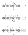
Figur 4 eine Düsenanordnung des Ejektors inFiguren 1 bis 3 zusammen mit Rückschlagklappen in Alleinstellung in Seitenansicht; -
Figur 5 die Düsenanordnung inFigur 4 in einer um 180° um die Längsachse gedrehten Seitenansicht; -
Figur 6 die Düsenanordnung inFiguren 4 und 5 unter Weglassung der Rückschlagklappen; -
Figur 7 eine Rückschlagklappe in perspektivischer Ansicht in Alleinstellung; und -
Figur 8 den Ejektor inFigur 1a ) in einem Schnitt entlang der Linie VIII-VIII in Figur 1a). - In
Fig. 1a ) und b) sowieFig. 2a ) und b) ist ein mit dem allgemeinen Bezugszeichen 10 versehener mehrstufiger Ejektor gezeigt. Weitere Einzelheiten des Ejektors 10 gehen aus denFig. 3 bis 8 hervor. - Der Ejektor 10 wird zur Erzeugung eines Unterdrucks bzw. Vakuums verwendet.
- Der Ejektor 10 weist eine Düsenanordnung 12 mit im gezeigten Ausführungsbeispiel insgesamt vier Düsen 14, 16, 18 und 20 auf. Die Düsen 14, 16, 18 und 20 sind in Richtung einer Längsachse 21 in Reihe angeordnet.
- Die Düsen 14, 16, 18 und 20 sind dazu ausgelegt, von einem Fluid, insbesondere Druckluft, durchströmt zu werden. In
Fig. 1b ) und2b ) ist die Fluidströmung eingangsseitig mit einem Pfeil 22 und ausgangsseitig mit Pfeilen 24 angedeutet. - In Strömungsrichtung des Fluids gesehen bildet die Düse 14 die Treibdüse, und die Düsen 16, 18 und 20 bilden die Empfängerdüsen. Die Düse 14 weist gemäß
Fig. 1a ) einen Fluiddurchtrittskanal 26, die Düse 16 einen Fluiddurchtrittskanal 28, die Düse 18 einen Fluiddurchtrittskanal 30 und die Düse 20 einen Fluiddurchtrittskanal 32 auf. Dabei ist ein Durchtrittsquerschnitt des Fluiddurchtrittskanals 28 größer als ein Durchtrittsquerschnitt des Fluiddurchtrittskanals 26, und der Fluiddurchtrittskanal 30 weist einen größeren Durchtrittsquerschnitt als der Fluiddurchtrittskanal 28 und der Fluiddurchtrittskanal 32 weist einen größeren Durchtrittsquerschnitt als der Fluiddurchtrittskanal 30 auf. - Die Düsen 16, 18, 20 sind einstückig zu einem Düsenstrang 34 miteinander verbunden. Die Düse 14 ist als Einzeldüse ausgebildet.
- In
Fig. 6 ist die Düsenanordnung 12 mit dem Düsenstrang 34 und der Düse 14 in Alleinstellung gezeigt. - Der Düsenstrang 34 ist insgesamt einstückig aus Kunststoff gefertigt. Die Düse 14 ist beispielsweise aus Aluminium gefertigt.
- Die Düsen 14, 16, 18 und 20 lassen gemäß
Fig. 1a ) undFig. 6 zwischen sich jeweils einen Fluidspalt frei, und zwar einen Fluidspalt 36 zwischen der Düse 14 und der Düse 16, einen Fluidspalt 38 zwischen der Düse 16 und der Düse 18 sowie einen Fluidspalt 40 zwischen der Düse 18 und der Düse 20. - Um einerseits die einstückige Verbindung der Düsen 16, 18 und 20, andererseits die Fluidspalte 38 und 40 an dem Düsenstrang 34 zu realisieren, ist die Düse 16 mit der Düse 18 über eine Mehrzahl, hier drei, schmale axiale Stege 42 einstückig miteinander verbunden, und die Düse 18 ist mit der Düse 20 über schmale axiale Stege 44 einstückig verbunden. Die Stege 42 bzw. 44 sind um die Längsachse 21 herum verteilt und sorgen für einen ausreichend großen Öffnungsquerschnitt der Fluidspalte 38 und 40.
- Die Düse 14 sowie der Düsenstrang 34 mit den Düsen 16, 18 und 20 sind in einer insgesamt einstückigen Hülse zumindest teilweise aufgenommen. Die Hülse 46 weist ein erstes Ende 48 im Bereich der Düse 14 und ein zweites Ende 50 im Bereich der Düse 20 auf. Die Düse 20 überragt dabei das zweite Ende 50 der Hülse 46.
- Der Düsenstrang 34 und die Hülse 46 sind gemäß
Fig. 1a ) und b) sowieFiguren 2a ) und b) durch einen formschlüssig wirkenden Festlegemechanismus 52 axial, das heißt in Richtung der Längsachse 21, und in Drehrichtung um die Längsachse 21 aneinander festgelegt. Der Festlegemechanismus wird nachfolgend auch mit Bezug aufFig. 8 beschrieben. - Der Festlegemechanismus 52 ist an der Hülse 46 endseitig, und zwar im Bereich des zweiten Endes 50, angeordnet, während der Festlegemechanismus 52 an dem Düsenstrang 34 in einem Abstand von einem Ende 54 des Düsenstrangs 34 angeordnet ist.
- Der Festlegemechanismus 52 ist als Steck-Dreh-Verbindung ausgebildet, insbesondere als Bajonettverbindung. Dazu weist der Festlegemechanismus 52 zwei radial vorspringende Nasen 56 und 58 (siehe
Fig. 1 b) am Düsenstrang 34 auf, die sich teilumfänglich um die Längsachse 21 erstrecken. Die Nasen 56 und 58 sind um 180° um die Längsachse 21 zueinander versetzt. Die Nasen 56 und 58 weisen radiale Flächen 57 und 59 auf, die gekrümmt sind, jedoch mit einer Exzentrizität bezüglich der Längsachse 21. Auf diese Weise wirken die Flächen 57 und 59 als Anlaufschrägen beim Schließen des Festlegemechanismus 52, wenn der Düsenstrang 34 relativ zur Hülse 46 gedreht wird. - Der Festlegemechanismus 52 weist des Weiteren zwei sich in Richtung der Längsachse 21 erstreckende Ausnehmungen 60 und 62 auf, die als Nuten auf der Innenseite der Hülse 46 ausgebildet sind. Die Ausnehmungen 60 und 62 weisen eine Erstreckung in Umfangsrichtung um die Längsachse 21 auf, die etwas größer ist als die umfängliche Erstreckung der Nasen 56 und 58 am Düsenstrang 34. Die axiale Erstrekkung der Ausnehmungen 60 und 62 ist für die Ausnehmung 60 in
Fig. 1a ) mit unterbrochenen Linien angedeutet. Die Ausnehmungen 60 und 62 sind zum äußersten Ende des Endes 50 der Hülse 46 offen. - An die axiale Ausnehmung 60 schließt sich in Umfangsrichtung um die Längsachse 21 eine weitere Ausnehmung 64 an, und an die axiale Ausnehmung 62 schließt sich im gleichen Drehsinn eine weitere Ausnehmung 66 an. Die Ausnehmungen 64 und 66 sind als gegenüber dem zweiten Ende 50 zurückversetzte radiale Öffnungen in der Hülse 46 ausgebildet. Im aneinander festgelegten Zustand des Düsenstrangs 34 und der Hülse 46 greifen die radialen Nasen 56 und 58 in die Ausnehmungen 64 und 66 ein. Die radialen Nasen 56 und 58 weisen eine geringfügig größere radiale Erstreckung auf, als es dem Innendurchmesser der Hülse 46 im Bereich des zweiten Endes 50 entspricht, so dass die radialen Nasen 56 und 58 in die Ausnehmungen 64 und 66 einrasten können. Der Festlegemechanismus 52 ist somit nicht nur als Steck-Dreh-Verbindung in Form einer Bajonettverbindung ausgebildet, sondern zusätzlich auch als Rastverbindung.
- Der Düsenstrang 34 ist mittels des Festlegemechanismus 52 somit an der Hülse 46 axial und in Drehrichtung um die Längsachse 21 festlegbar.
- Der Düsenstrang 34 weist in einem Abstand von seinem Ende 54 einen Flansch 68 auf, der hier als vollumfänglicher radial vorspringender Ringflansch ausgebildet ist, der beim Festlegen des Düsenstrangs 34 und der Hülse 46 aneinander gegen eine Stirnseite 70 der Hülse 46 zu liegen kommt. Der Flansch 68 begrenzt somit die Einschubtiefe des Düsenstrangs 34 in die Hülse 46.
-
Fig. 1a ) und b) sowieFig. 2a ) und b) undFig. 8 zeigen den Ejektor 10 in einem Zustand, in dem der Düsenstrang 34 und die Hülse 46 mittels des Festlegemechanismus 52 aneinander festgelegt sind. Zum Lösen des Düsenstrangs 34 von der Hülse 46 wird ausgehend von der Stellung inFig. 8 der Düsenstrang 34 um die Längsachse 21 zunächst im Gegenuhrzeigersinn relativ zur Hülse 46 verdreht, wodurch die radialen Nasen 56 und 58 mit den Ausnehmungen 64 und 66 außer Eingriff kommen. Die radialen Nasen 56 und 58 treten dabei in die axialen Ausnehmungen 60 und 62 ein. Der hierzu benötigte Drehweg des Düsenstrangs 34 relativ zur Hülse 46 beträgt etwa 40°, zumindest jedoch weniger als 45°. Nach dem wie zuvor beschriebenen Drehen des Düsenstrangs 34 relativ zur Hülse 46 kann der Düsenstrang 34 vollständig aus der Hülse 46 herausgezogen werden, wie inFig. 3 mit einem Pfeil 72 angedeutet ist. Das Zusammenbauen des Ejektors 10, das heißt das Verbinden des Düsenstrangs 34 mit der Hülse 46 geschieht in umgekehrter Abfolge, das heißt der Düsenstrang 34 wird zunächst in die Hülse 46 eingesetzt, und zwar in einer relativen Drehlage zur Hülse 46, in der die radialen Nasen 56 und 58 in die axialen Ausnehmungen 60 und 62 eintauchen können. Wenn der Flansch 68 an die Stirnseite 70 anschlägt, wird der Düsenstrang 34 im Uhrzeigersinn (Fig. 8 ) relativ zur Hülse 46 verdreht, bis die radialen Nasen 56 und 58 mit den Ausnehmungen 64 und 66 in Eingriff kommen. Die abgeschrägten Flächen 57 und 59 der Nasen 56 und 58 verringern den Kraftaufwand beim Drehen und gewährleisten ein deutlich spürbares Einrasten der Nasen 56 und 58 in die Ausnehmungen 64 und 66, indem das beim Drehen des Düsenstranges 34 zum Schließen des Festlegemechanismus 52 vorauseilende Ende der Nasen 56 und 58 eine geringere radiale Erstreckung aufweist als das nachlaufende Ende. - Die Hülse 46 weist des Weiteren mehrere, hier sechs, radiale Öffnungen 74a, 74b, 76a, 76b, 78a und 78b auf, die ein Kommunizieren des Innenraums der Hülse 46 mit ihrem Außenraum ermöglichen. Zum Freigeben und Verschließen der Öffnungen 74a,b; 76a,b und 78a,b sind Rückschlagklappen 80, 82 und 84 vorgesehen, von denen die Rückschlagklappen 82 und 84 mit dem Düsenstrang 34 verbunden sind, während die Rückschlagklappe 80 mit der Düse 14 verbunden ist. Die Rückschlagklappen 82 und 84 sind lose mit dem Düsenstrang 34 verbunden, und die Rückschlagklappe 80 ist lose mit der Düse 14 verbunden. Die Rückschlagklappen 80, 82 und 84 können somit von der Düse 14 bzw. von dem Düsenstrang 34 zum Zwecke des Austausches bei Verschleiß abgenommen werden.
- Die Ausgestaltung der Rückschlagklappen wird nachfolgend unter anderem mit Bezug auf
Fig. 4 und 5 sowie 7 beschrieben.Fig. 7 zeigt die Rückschlagklappe 84 beispielhaft in Alleinstellung. Die gleiche Beschreibung gilt auch für die beiden anderen Rückschlagklappen 80 und 82. - Die Rückschlagklappe 84, die insgesamt aus einem Elastomer bzw. Gummi gefertigt ist, ein geschlitztes Ringband 86 auf, das aufgrund seiner umfänglichen Unterbrechung zwei Flügel 88 und 90 ausbildet. Im am Düsenstrang 34 angebrachten Zustand dient der Flügel 88 zum Verschließen der Öffnung 78b und der Flügel 90 zum Verschließen der Öffnung 78a der Hülse 46.
- Das Ringband 86 ist über einen axialen Steg 92 mit einem teilumfänglichen bzw. unterbrochenen Ring 94 einstückig verbunden.
- Wie mit Bezug auf die Rückschlagklappe 84 nachfolgend beschrieben wird, sind die Rückschlagklappen 80, 82 und 84 an der Düse 14 bzw. an dem Düsenstrang 34 gegen Verdrehung um die Längsachse 21 und gegen Verschieben in Richtung der Längsachse 21 relativ zur Düse 14 bzw. zum Düsenstrang 34 gesichert.
- Hierzu ist für die Rückschlagklappe 84 gemäß
Fig. 4 am Düsenstrang 34 ein Sitz 95 ausgebildet, der durch zwei radiale Flansche 96 und 98, die als vollumfängliche Ringflansche ausgebildet sind, und deren Abstand der Dicke des Rings 94 entspricht, gebildet wird. Zwischen die beiden Flansche 96 und 98 wird der Ring 84 beim Anbringen der Rückschlagklappe 84 an dem Düsenstrang 34 eingesetzt. Zwischen den Flanschen 96 und 98 ist die Rückschlagklappe 84 somit axial gegen Verschieben gesichert. Der Schlitz 95 weist weiterhin eine radiale Nase 100 zwischen den beiden Flanschen 96 und 98 auf, die die Drehlage der Rückschlagklappe 84 relativ zum Düsenstrang 34 bezüglich der Längsachse 21 und über den Festlegemechanismus 52 relativ zu den Öffnungen 78a und 78b definiert und die Rückschlagklappe 84 außerdem gegen ein Verdrehen um die Längsachse 21 relativ zum Düsenstrang 34 sichert. Die Rückschlagklappe 84 wird dazu so an dem Düsenstrang 34 angebracht, dass ein geschlitzter Bereich 102 des Rings 94 auf Höhe der Nase 100 zu liegen kommt, so dass sich die beiden Enden 104 und 106 des Rings 94 beidseits der Nase 100 abstützen. - Beim Zusammenbau des Ejektors 10 werden die Rückschlagklappen 82 und 84 zunächst in der vorgegebenen axialen Position und Drehlage an dem Düsenstrang 34 angebracht. Anschließend wird der Düsenstrang 34 in die Hülse 46 eingeschoben, wobei durch die axiale Sicherung der Rückschlagklappen 82 und 84 an dem Düsenstrang 34 diese beim Einschieben des Düsenstrangs 34 in die Hülse 46 nicht axial relativ zum Düsenstrang 34 verschoben werden können. Beim anschließenden Verdrehen des Düsenstrangs 34 relativ zur Hülse 46 zum Schließen des Festlegemechanismus 52 verhindert die Verdrehsicherung der Rückschlagklappen 82 und 84 an dem Düsenstrang 34 eine unerwünschte Verdrehung der Rückschlagklappen 82 und 84 relativ zum Düsenstrang 34.
- Die Düsen 14, 16, 18 und 20 weisen ferner Aufnahmen bzw. Sitze 108, 110, 112 und 114 zur Aufnahme jeweils einer Ringdichtung (in der Zeichnung weggelassen) auf, um die Düsen 14, 16, 18 und 20 abschnittsweise gegen die Hülse 46 abzudichten.
- Der Ejektor 10 wird im Gebrauch in ein nicht dargestelltes Ejektorgehäuse eingesetzt, das eine an den Außendurchmesser der Hülse 46 entsprechend angepasste Bohrung aufweist. Muss der Ejektor 10 zu Wartungszwecken aus dem Ejektorgehäuse herausgenommen werden, verhindert der zuvor beschriebene Festlegemechanismus 52, über den der Düsenstrang 34 und die Hülse 46 aneinander festgelegt sind, dass bei Ausüben einer axialen Zugkraft auf den Düsenstrang 34 sich der Düsenstrang 34 von der Hülse 46 vorzeitig löst und nur der Düsenstrang 34 aus dem Ejektorgehäuse herausgezogen wird, während die Hülse 46 in dem Ejektorgehäuse stecken bleibt. Andererseits ermöglicht der Festlegemechanismus 52 ein einfaches Zerlegen des Ejektors 10 in den Düsenstrang 34 und die Hülse 46 und auch ein leichtes Zusammensetzen dieser Teile. Beim Einsetzen des Düsenstrangs 34 in die Hülse 46 ändert sich auch nicht die Lage und Orientierung der Rückschlagklappen 82 und 84 relativ zum Düsenstrang 34, wie zuvor beschrieben wurde.
Claims (12)
- Mehrstufiger Ejektor, mit einer Düsenanordnung (12), die zumindest drei Düsen (14, 16, 18, 20) aufweist, die in Richtung einer Längsachse (21) in Reihe angeordnet sind, wobei die Düsen (14, 16, 18, 20) dazu ausgelegt sind, von einem Fluid durchströmt zu werden, wobei zwischen benachbarten der Düsen (14, 16, 18, 20) jeweils ein Fluidspalt (36, 38, 40) vorhanden ist, wobei zumindest zwei der zumindest drei Düsen (14, 16, 18, 20) einstückig zu einem Düsenstrang (34) miteinander verbunden sind, und wobei der Düsenstrang (34) zumindest teilweise in einer Hülse (46) angeordnet und der Düsenstrang (34) und die Hülse (46) aneinander lösbar festgelegt sind, dadurch gekennzeichnet, dass der Düsenstrang (34) und die Hülse (46) durch einen formschlüssig wirkenden Festlegemechanismus (52) axial aneinander festgelegt sind.
- Ejektor nach Anspruch 1, dadurch gekennzeichnet, dass der Festlegemechanismus (52) den Düsenstrang (34) und die Hülse (46) relativ zueinander drehgesichert aneinander festlegt.
- Ejektor nach Anspruch 1 oder 2, dadurch gekennzeichnet, dass der Festlegemechanismus (52) als Steck-Dreh-Verbindung, insbesondere als Bajonettverbindung ausgebildet ist.
- Ejektor nach einem der Ansprüche 1 bis 3, dadurch gekennzeichnet, dass der Festlegemechanismus (52) als Rastverbindung ausgebildet ist.
- Ejektor nach Anspruch 3 und 4, dadurch gekennzeichnet, dass der Festlegemechanismus (52) als Steck-Dreh-Verbindung und als Rastverbindung ausgebildet ist.
- Ejektor nach einem der Ansprüche 1 bis 5, dadurch gekennzeichnet, dass der Festlegemechanismus (52) an dem Düsenstrang (34) in einem Abstand von einem Ende (54) des Düsenstrangs (34) angeordnet ist, so dass der Düsenstrang (34) die Hülse (46) überragt.
- Ejektor nach einem der Ansprüche 1 bis 6, dadurch gekennzeichnet, dass der Festlegemechanismus (52) zumindest eine radial vorspringende Nase (56, 58) an dem Düsenstrang (34) und zumindest eine sich in Richtung der Längsachse (21) erstreckende Ausnehmung (60, 62), an die sich eine in Umfangsrichtung um die Längsachse (21) erstreckende Ausnehmung (64, 66) anschließt, an der Hülse (46) aufweist.
- Ejektor nach einem der Ansprüche 1 bis 7, dadurch gekennzeichnet, dass der Düsenstrang (34) einen Flansch (68) aufweist, der beim Verbinden des Düsenstrangs (34) mit der Hülse (46) gegen eine Stirnseite (70) der Hülse (46) zu liegen kommt.
- Ejektor nach einem der Ansprüche 1 bis 8, dadurch gekennzeichnet, dass die Hülse (46) zumindest eine radiale Öffnung (76a, 76b, 78a, 78b) aufweist, und dass zwischen dem Düsenstrang (34) und der Hülse (46) zumindest eine Rückschlagklappe (82, 84) zum Verschließen und Freigeben der Öffnung (76a, 76b, 78a, 78b) abnehmbar am Düsenstrang (34) angeordnet ist, wobei die Rückschlagklappe (82, 84) an dem Düsenstrang (34) gegen Verdrehung um die Längsachse (21) und/oder gegen Verschieben in Richtung der Längsachse (21) relativ zum Düsenstrang (34) gesichert ist.
- Ejektor nach Anspruch 9, dadurch gekennzeichnet, dass die zumindest eine Rückschlagklappe (82, 84) einen teilumfänglichen Ring (94) aufweist, wobei der Düsenstrang (34) einen Sitz (95) zur drehgesicherten und/oder axial gesicherten Aufnahme des Rings (94) aufweist.
- Ejektor nach einem der Ansprüche 1 bis 10, dadurch gekennzeichnet, dass die zumindest drei Düsen (14, 16, 18, 20) eine Treibdüse (14) und zumindest zwei Empfängerdüsen (16, 18, 20) aufweisen, wobei die zumindest zwei Empfängerdüsen (16, 18, 20) den einstückigen Düsenstrang (34) bilden.
- Ejektor nach einem der Ansprüche 1 bis 11, dadurch gekennzeichnet, dass die Düsenanordnung (12) zumindest vier Düsen (14, 16, 18, 20) aufweist, die eine Treibdüse (14) und zumindest drei Empfängerdüsen (16, 18, 20) aufweisen, wobei die zumindest drei Empfängerdüsen (16, 18, 20) den einstückigen Düsenstrang (34) bilden.
Applications Claiming Priority (1)
| Application Number | Priority Date | Filing Date | Title |
|---|---|---|---|
| DE102013107537.1A DE102013107537B4 (de) | 2013-07-16 | 2013-07-16 | Mehrstufiger Ejektor |
Publications (2)
| Publication Number | Publication Date |
|---|---|
| EP2827004A1 EP2827004A1 (de) | 2015-01-21 |
| EP2827004B1 true EP2827004B1 (de) | 2015-10-14 |
Family
ID=51205176
Family Applications (1)
| Application Number | Title | Priority Date | Filing Date |
|---|---|---|---|
| EP14175046.3A Active EP2827004B1 (de) | 2013-07-16 | 2014-06-30 | Mehrstufiger Ejektor |
Country Status (5)
| Country | Link |
|---|---|
| US (1) | US9863443B2 (de) |
| EP (1) | EP2827004B1 (de) |
| KR (1) | KR101687067B1 (de) |
| CN (1) | CN104295536B (de) |
| DE (1) | DE102013107537B4 (de) |
Families Citing this family (9)
| Publication number | Priority date | Publication date | Assignee | Title |
|---|---|---|---|---|
| SE539775C2 (sv) * | 2014-06-23 | 2017-11-28 | Onishi Teknik Ab | Flerstegs vakuumejektor |
| CN105854328B (zh) * | 2016-05-11 | 2017-12-15 | 耒阳金悦科技发展有限公司 | 一种工业分离方法 |
| CN105833559B (zh) * | 2016-05-11 | 2017-12-15 | 耒阳金悦科技发展有限公司 | 一种工业分离设备 |
| CN108317108A (zh) * | 2018-04-12 | 2018-07-24 | 微可为(厦门)真空科技有限公司 | 一种超音速真空管 |
| KR102344214B1 (ko) * | 2021-05-18 | 2021-12-28 | (주)브이텍 | 진공 이젝터 펌프 |
| FR3124559B1 (fr) | 2021-06-24 | 2025-03-07 | Coval | Générateur de vide multi-étages |
| EP4400729B1 (de) * | 2022-12-20 | 2026-02-04 | Sel Franco, Luiz Tadeu | Vakuumerzeuger mit mehreren saugdüsen, befestigungsmittel-vakuumerzeuger mit mehreren saugdüsen und vakuumerzeugerpumpe |
| TWI880231B (zh) * | 2023-06-02 | 2025-04-11 | 台灣氣立股份有限公司 | 具有渦旋氣流與多段位吸入孔之三段式真空發生器 |
| EP4560144A1 (de) | 2023-11-23 | 2025-05-28 | Piab Aktiebolag | Ejektorvakuumpumpe |
Family Cites Families (10)
| Publication number | Priority date | Publication date | Assignee | Title |
|---|---|---|---|---|
| GB191114770A (en) * | 1911-06-21 | 1911-11-09 | Carl Pottel | An Improvement in Injectors. |
| GB802273A (en) * | 1954-10-20 | 1958-10-01 | Juan Asensio Carrasco | Convector apparatus for promoting water circulation in steam boilers |
| DE3425566A1 (de) * | 1984-07-11 | 1986-01-16 | Draenert Klaus | Vorrichtung und verfahren zum mischen und applizieren von knochenzement |
| US5683227A (en) * | 1993-03-31 | 1997-11-04 | Smc Corporation | Multistage ejector assembly |
| DE29719975U1 (de) | 1997-11-11 | 1998-01-08 | Richter, Siegfried, Dipl.-Ing. (FH), 88605 Sauldorf | Mit Druckluft betriebene Saugdüse |
| SE511716E5 (sv) * | 1998-03-20 | 2009-01-28 | Piab Ab | Ejektorpump |
| SE519647C2 (sv) * | 2002-05-03 | 2003-03-25 | Piab Ab | Vakuumpump och sätt att tillhandahålla undertryck |
| KR100578540B1 (ko) | 2004-07-28 | 2006-05-15 | 한국뉴매틱(주) | 진공 이젝터 펌프 |
| KR100629994B1 (ko) | 2005-12-30 | 2006-10-02 | 한국뉴매틱(주) | 진공 이젝터 펌프 |
| KR101039470B1 (ko) | 2010-10-22 | 2011-06-07 | 이우승 | 진공 이젝터 펌프 |
-
2013
- 2013-07-16 DE DE102013107537.1A patent/DE102013107537B4/de not_active Expired - Fee Related
-
2014
- 2014-06-30 EP EP14175046.3A patent/EP2827004B1/de active Active
- 2014-07-10 US US14/327,818 patent/US9863443B2/en active Active
- 2014-07-15 CN CN201410336187.2A patent/CN104295536B/zh active Active
- 2014-07-15 KR KR1020140089044A patent/KR101687067B1/ko active Active
Also Published As
| Publication number | Publication date |
|---|---|
| US9863443B2 (en) | 2018-01-09 |
| US20150076249A1 (en) | 2015-03-19 |
| DE102013107537B4 (de) | 2015-02-19 |
| DE102013107537A1 (de) | 2015-01-22 |
| CN104295536A (zh) | 2015-01-21 |
| KR101687067B1 (ko) | 2016-12-15 |
| EP2827004A1 (de) | 2015-01-21 |
| CN104295536B (zh) | 2016-11-23 |
| KR20150009464A (ko) | 2015-01-26 |
Similar Documents
| Publication | Publication Date | Title |
|---|---|---|
| DE102013107537B4 (de) | Mehrstufiger Ejektor | |
| DE2011409C3 (de) | Ventilschnellkupplung fur zwei gas- oder flussigkeitsfuhrende Leitungen | |
| DE112008001038B4 (de) | Vierritzeldifferential mit Kreuzbolzenhalteeinheit und zugehöriges Verfahren zum Zusammenbau | |
| EP2799751B1 (de) | Fluidleitungskupplung | |
| DE102017220448A1 (de) | Fluidleitungskupplung mit Sicherungsklammer | |
| DE102009018930A1 (de) | Rückschlagventil | |
| DE102011109788A1 (de) | Anschlussvorrichtung zum Anschließen einer Fluidleitung | |
| DE102010005821A1 (de) | Schmierung einer drehbaren Welle | |
| EP2739518B1 (de) | Lenkspindelanordnung | |
| DE202008010717U1 (de) | Sanitärer Wasserauslauf | |
| EP2154299A2 (de) | Sanitäre Funktionseinheit | |
| EP3312352A1 (de) | Einsetzteil mit einem wasserführenden patronengehäuse | |
| DE3041829A1 (de) | Fluessigkeitskupplung | |
| EP2715200B1 (de) | Spielfreie steckverbindung für rohr- oder schlauchleitungen | |
| EP4111006A1 (de) | Strahlregler mit verdrehsicherung von bauteilen | |
| EP3024708B1 (de) | Hauptbremszylinderanordnung einer kraftfahrzeugbremsanlage mit filterelement sowie fluidreservoir und einsatzelement hierfür | |
| EP2705268B1 (de) | Hydraulische strecke mit einer entlüftungseinrichtung | |
| DE202013001994U1 (de) | Strahlregler mit einem Einbaugehäuse und einem darin einsetzbaren Strahlzerleger | |
| EP3534019B1 (de) | Kugelsperrbolzen | |
| DE102016008554A1 (de) | Welle mit axialem Fluiddurchgang | |
| EP3068690B1 (de) | Sitzbefestigungsvorrichtung | |
| DE102013011527B4 (de) | Befestigungsanordnung | |
| DE102015203045A1 (de) | Kupplungsanordnung | |
| DE102008056960B3 (de) | Ventil | |
| EP4035719B1 (de) | Vorrichtung zur verabreichung eines flüssigen medikaments |
Legal Events
| Date | Code | Title | Description |
|---|---|---|---|
| 17P | Request for examination filed |
Effective date: 20140630 |
|
| AK | Designated contracting states |
Kind code of ref document: A1 Designated state(s): AL AT BE BG CH CY CZ DE DK EE ES FI FR GB GR HR HU IE IS IT LI LT LU LV MC MK MT NL NO PL PT RO RS SE SI SK SM TR |
|
| AX | Request for extension of the european patent |
Extension state: BA ME |
|
| PUAI | Public reference made under article 153(3) epc to a published international application that has entered the european phase |
Free format text: ORIGINAL CODE: 0009012 |
|
| R17P | Request for examination filed (corrected) |
Effective date: 20150121 |
|
| RBV | Designated contracting states (corrected) |
Designated state(s): AL AT BE BG CH CY CZ DE DK EE ES FI FR GB GR HR HU IE IS IT LI LT LU LV MC MK MT NL NO PL PT RO RS SE SI SK SM TR |
|
| GRAP | Despatch of communication of intention to grant a patent |
Free format text: ORIGINAL CODE: EPIDOSNIGR1 |
|
| INTG | Intention to grant announced |
Effective date: 20150602 |
|
| GRAS | Grant fee paid |
Free format text: ORIGINAL CODE: EPIDOSNIGR3 |
|
| GRAA | (expected) grant |
Free format text: ORIGINAL CODE: 0009210 |
|
| AK | Designated contracting states |
Kind code of ref document: B1 Designated state(s): AL AT BE BG CH CY CZ DE DK EE ES FI FR GB GR HR HU IE IS IT LI LT LU LV MC MK MT NL NO PL PT RO RS SE SI SK SM TR |
|
| REG | Reference to a national code |
Ref country code: GB Ref legal event code: FG4D Free format text: NOT ENGLISH |
|
| REG | Reference to a national code |
Ref country code: AT Ref legal event code: REF Ref document number: 755360 Country of ref document: AT Kind code of ref document: T Effective date: 20151015 Ref country code: CH Ref legal event code: EP |
|
| REG | Reference to a national code |
Ref country code: NL Ref legal event code: MP Effective date: 20151014 |
|
| REG | Reference to a national code |
Ref country code: IE Ref legal event code: FG4D Free format text: LANGUAGE OF EP DOCUMENT: GERMAN |
|
| REG | Reference to a national code |
Ref country code: DE Ref legal event code: R096 Ref document number: 502014000145 Country of ref document: DE |
|
| REG | Reference to a national code |
Ref country code: SE Ref legal event code: TRGR |
|
| REG | Reference to a national code |
Ref country code: LT Ref legal event code: MG4D |
|
| PG25 | Lapsed in a contracting state [announced via postgrant information from national office to epo] |
Ref country code: IS Free format text: LAPSE BECAUSE OF FAILURE TO SUBMIT A TRANSLATION OF THE DESCRIPTION OR TO PAY THE FEE WITHIN THE PRESCRIBED TIME-LIMIT Effective date: 20160214 Ref country code: LT Free format text: LAPSE BECAUSE OF FAILURE TO SUBMIT A TRANSLATION OF THE DESCRIPTION OR TO PAY THE FEE WITHIN THE PRESCRIBED TIME-LIMIT Effective date: 20151014 Ref country code: NL Free format text: LAPSE BECAUSE OF FAILURE TO SUBMIT A TRANSLATION OF THE DESCRIPTION OR TO PAY THE FEE WITHIN THE PRESCRIBED TIME-LIMIT Effective date: 20151014 Ref country code: ES Free format text: LAPSE BECAUSE OF FAILURE TO SUBMIT A TRANSLATION OF THE DESCRIPTION OR TO PAY THE FEE WITHIN THE PRESCRIBED TIME-LIMIT Effective date: 20151014 Ref country code: HR Free format text: LAPSE BECAUSE OF FAILURE TO SUBMIT A TRANSLATION OF THE DESCRIPTION OR TO PAY THE FEE WITHIN THE PRESCRIBED TIME-LIMIT Effective date: 20151014 Ref country code: NO Free format text: LAPSE BECAUSE OF FAILURE TO SUBMIT A TRANSLATION OF THE DESCRIPTION OR TO PAY THE FEE WITHIN THE PRESCRIBED TIME-LIMIT Effective date: 20160114 |
|
| PG25 | Lapsed in a contracting state [announced via postgrant information from national office to epo] |
Ref country code: LV Free format text: LAPSE BECAUSE OF FAILURE TO SUBMIT A TRANSLATION OF THE DESCRIPTION OR TO PAY THE FEE WITHIN THE PRESCRIBED TIME-LIMIT Effective date: 20151014 Ref country code: FI Free format text: LAPSE BECAUSE OF FAILURE TO SUBMIT A TRANSLATION OF THE DESCRIPTION OR TO PAY THE FEE WITHIN THE PRESCRIBED TIME-LIMIT Effective date: 20151014 Ref country code: GR Free format text: LAPSE BECAUSE OF FAILURE TO SUBMIT A TRANSLATION OF THE DESCRIPTION OR TO PAY THE FEE WITHIN THE PRESCRIBED TIME-LIMIT Effective date: 20160115 Ref country code: PT Free format text: LAPSE BECAUSE OF FAILURE TO SUBMIT A TRANSLATION OF THE DESCRIPTION OR TO PAY THE FEE WITHIN THE PRESCRIBED TIME-LIMIT Effective date: 20160215 Ref country code: PL Free format text: LAPSE BECAUSE OF FAILURE TO SUBMIT A TRANSLATION OF THE DESCRIPTION OR TO PAY THE FEE WITHIN THE PRESCRIBED TIME-LIMIT Effective date: 20151014 Ref country code: RS Free format text: LAPSE BECAUSE OF FAILURE TO SUBMIT A TRANSLATION OF THE DESCRIPTION OR TO PAY THE FEE WITHIN THE PRESCRIBED TIME-LIMIT Effective date: 20151014 |
|
| REG | Reference to a national code |
Ref country code: FR Ref legal event code: PLFP Year of fee payment: 3 |
|
| REG | Reference to a national code |
Ref country code: DE Ref legal event code: R097 Ref document number: 502014000145 Country of ref document: DE |
|
| PG25 | Lapsed in a contracting state [announced via postgrant information from national office to epo] |
Ref country code: CZ Free format text: LAPSE BECAUSE OF FAILURE TO SUBMIT A TRANSLATION OF THE DESCRIPTION OR TO PAY THE FEE WITHIN THE PRESCRIBED TIME-LIMIT Effective date: 20151014 |
|
| PLBE | No opposition filed within time limit |
Free format text: ORIGINAL CODE: 0009261 |
|
| STAA | Information on the status of an ep patent application or granted ep patent |
Free format text: STATUS: NO OPPOSITION FILED WITHIN TIME LIMIT |
|
| PG25 | Lapsed in a contracting state [announced via postgrant information from national office to epo] |
Ref country code: RO Free format text: LAPSE BECAUSE OF FAILURE TO SUBMIT A TRANSLATION OF THE DESCRIPTION OR TO PAY THE FEE WITHIN THE PRESCRIBED TIME-LIMIT Effective date: 20151014 Ref country code: SK Free format text: LAPSE BECAUSE OF FAILURE TO SUBMIT A TRANSLATION OF THE DESCRIPTION OR TO PAY THE FEE WITHIN THE PRESCRIBED TIME-LIMIT Effective date: 20151014 Ref country code: DK Free format text: LAPSE BECAUSE OF FAILURE TO SUBMIT A TRANSLATION OF THE DESCRIPTION OR TO PAY THE FEE WITHIN THE PRESCRIBED TIME-LIMIT Effective date: 20151014 Ref country code: SM Free format text: LAPSE BECAUSE OF FAILURE TO SUBMIT A TRANSLATION OF THE DESCRIPTION OR TO PAY THE FEE WITHIN THE PRESCRIBED TIME-LIMIT Effective date: 20151014 Ref country code: EE Free format text: LAPSE BECAUSE OF FAILURE TO SUBMIT A TRANSLATION OF THE DESCRIPTION OR TO PAY THE FEE WITHIN THE PRESCRIBED TIME-LIMIT Effective date: 20151014 |
|
| 26N | No opposition filed |
Effective date: 20160715 |
|
| PG25 | Lapsed in a contracting state [announced via postgrant information from national office to epo] |
Ref country code: SI Free format text: LAPSE BECAUSE OF FAILURE TO SUBMIT A TRANSLATION OF THE DESCRIPTION OR TO PAY THE FEE WITHIN THE PRESCRIBED TIME-LIMIT Effective date: 20151014 |
|
| PG25 | Lapsed in a contracting state [announced via postgrant information from national office to epo] |
Ref country code: BE Free format text: LAPSE BECAUSE OF NON-PAYMENT OF DUE FEES Effective date: 20160630 |
|
| PG25 | Lapsed in a contracting state [announced via postgrant information from national office to epo] |
Ref country code: MC Free format text: LAPSE BECAUSE OF FAILURE TO SUBMIT A TRANSLATION OF THE DESCRIPTION OR TO PAY THE FEE WITHIN THE PRESCRIBED TIME-LIMIT Effective date: 20151014 |
|
| REG | Reference to a national code |
Ref country code: IE Ref legal event code: MM4A |
|
| PG25 | Lapsed in a contracting state [announced via postgrant information from national office to epo] |
Ref country code: IE Free format text: LAPSE BECAUSE OF NON-PAYMENT OF DUE FEES Effective date: 20160630 |
|
| REG | Reference to a national code |
Ref country code: FR Ref legal event code: PLFP Year of fee payment: 4 |
|
| REG | Reference to a national code |
Ref country code: CH Ref legal event code: PL |
|
| PG25 | Lapsed in a contracting state [announced via postgrant information from national office to epo] |
Ref country code: CH Free format text: LAPSE BECAUSE OF NON-PAYMENT OF DUE FEES Effective date: 20170630 Ref country code: LI Free format text: LAPSE BECAUSE OF NON-PAYMENT OF DUE FEES Effective date: 20170630 |
|
| PG25 | Lapsed in a contracting state [announced via postgrant information from national office to epo] |
Ref country code: HU Free format text: LAPSE BECAUSE OF FAILURE TO SUBMIT A TRANSLATION OF THE DESCRIPTION OR TO PAY THE FEE WITHIN THE PRESCRIBED TIME-LIMIT; INVALID AB INITIO Effective date: 20140630 |
|
| REG | Reference to a national code |
Ref country code: FR Ref legal event code: PLFP Year of fee payment: 5 |
|
| PG25 | Lapsed in a contracting state [announced via postgrant information from national office to epo] |
Ref country code: CY Free format text: LAPSE BECAUSE OF FAILURE TO SUBMIT A TRANSLATION OF THE DESCRIPTION OR TO PAY THE FEE WITHIN THE PRESCRIBED TIME-LIMIT Effective date: 20151014 Ref country code: MK Free format text: LAPSE BECAUSE OF FAILURE TO SUBMIT A TRANSLATION OF THE DESCRIPTION OR TO PAY THE FEE WITHIN THE PRESCRIBED TIME-LIMIT Effective date: 20151014 Ref country code: LU Free format text: LAPSE BECAUSE OF NON-PAYMENT OF DUE FEES Effective date: 20160630 Ref country code: MT Free format text: LAPSE BECAUSE OF FAILURE TO SUBMIT A TRANSLATION OF THE DESCRIPTION OR TO PAY THE FEE WITHIN THE PRESCRIBED TIME-LIMIT Effective date: 20151014 |
|
| PG25 | Lapsed in a contracting state [announced via postgrant information from national office to epo] |
Ref country code: BG Free format text: LAPSE BECAUSE OF FAILURE TO SUBMIT A TRANSLATION OF THE DESCRIPTION OR TO PAY THE FEE WITHIN THE PRESCRIBED TIME-LIMIT Effective date: 20151014 |
|
| PG25 | Lapsed in a contracting state [announced via postgrant information from national office to epo] |
Ref country code: TR Free format text: LAPSE BECAUSE OF FAILURE TO SUBMIT A TRANSLATION OF THE DESCRIPTION OR TO PAY THE FEE WITHIN THE PRESCRIBED TIME-LIMIT Effective date: 20151014 Ref country code: AL Free format text: LAPSE BECAUSE OF FAILURE TO SUBMIT A TRANSLATION OF THE DESCRIPTION OR TO PAY THE FEE WITHIN THE PRESCRIBED TIME-LIMIT Effective date: 20151014 |
|
| GBPC | Gb: european patent ceased through non-payment of renewal fee |
Effective date: 20180630 |
|
| PG25 | Lapsed in a contracting state [announced via postgrant information from national office to epo] |
Ref country code: GB Free format text: LAPSE BECAUSE OF NON-PAYMENT OF DUE FEES Effective date: 20180630 |
|
| REG | Reference to a national code |
Ref country code: AT Ref legal event code: MM01 Ref document number: 755360 Country of ref document: AT Kind code of ref document: T Effective date: 20190630 |
|
| PG25 | Lapsed in a contracting state [announced via postgrant information from national office to epo] |
Ref country code: AT Free format text: LAPSE BECAUSE OF NON-PAYMENT OF DUE FEES Effective date: 20190630 |
|
| PGFP | Annual fee paid to national office [announced via postgrant information from national office to epo] |
Ref country code: FR Payment date: 20250624 Year of fee payment: 12 |
|
| PGFP | Annual fee paid to national office [announced via postgrant information from national office to epo] |
Ref country code: SE Payment date: 20250618 Year of fee payment: 12 |
|
| PGFP | Annual fee paid to national office [announced via postgrant information from national office to epo] |
Ref country code: DE Payment date: 20250730 Year of fee payment: 12 |
|
| PGFP | Annual fee paid to national office [announced via postgrant information from national office to epo] |
Ref country code: IT Payment date: 20250624 Year of fee payment: 12 |