EP2826583A1 - Optisches Messsytem zur Positionsbestimmung einer Elektrode bei der elektrochemischen Bearbeitung von Bauteilen - Google Patents
Optisches Messsytem zur Positionsbestimmung einer Elektrode bei der elektrochemischen Bearbeitung von Bauteilen Download PDFInfo
- Publication number
- EP2826583A1 EP2826583A1 EP14176127.0A EP14176127A EP2826583A1 EP 2826583 A1 EP2826583 A1 EP 2826583A1 EP 14176127 A EP14176127 A EP 14176127A EP 2826583 A1 EP2826583 A1 EP 2826583A1
- Authority
- EP
- European Patent Office
- Prior art keywords
- electrode
- optical measuring
- measuring system
- light source
- detection device
- Prior art date
- Legal status (The legal status is an assumption and is not a legal conclusion. Google has not performed a legal analysis and makes no representation as to the accuracy of the status listed.)
- Granted
Links
Images


Classifications
-
- C—CHEMISTRY; METALLURGY
- C25—ELECTROLYTIC OR ELECTROPHORETIC PROCESSES; APPARATUS THEREFOR
- C25F—PROCESSES FOR THE ELECTROLYTIC REMOVAL OF MATERIALS FROM OBJECTS; APPARATUS THEREFOR
- C25F3/00—Electrolytic etching or polishing
- C25F3/16—Polishing
-
- B—PERFORMING OPERATIONS; TRANSPORTING
- B23—MACHINE TOOLS; METAL-WORKING NOT OTHERWISE PROVIDED FOR
- B23H—WORKING OF METAL BY THE ACTION OF A HIGH CONCENTRATION OF ELECTRIC CURRENT ON A WORKPIECE USING AN ELECTRODE WHICH TAKES THE PLACE OF A TOOL; SUCH WORKING COMBINED WITH OTHER FORMS OF WORKING OF METAL
- B23H7/00—Processes or apparatus applicable to both electrical discharge machining and electrochemical machining
- B23H7/26—Apparatus for moving or positioning electrode relatively to workpiece; Mounting of electrode
-
- C—CHEMISTRY; METALLURGY
- C25—ELECTROLYTIC OR ELECTROPHORETIC PROCESSES; APPARATUS THEREFOR
- C25F—PROCESSES FOR THE ELECTROLYTIC REMOVAL OF MATERIALS FROM OBJECTS; APPARATUS THEREFOR
- C25F7/00—Constructional parts, or assemblies thereof, of cells for electrolytic removal of material from objects; Servicing or operating
-
- G—PHYSICS
- G01—MEASURING; TESTING
- G01B—MEASURING LENGTH, THICKNESS OR SIMILAR LINEAR DIMENSIONS; MEASURING ANGLES; MEASURING AREAS; MEASURING IRREGULARITIES OF SURFACES OR CONTOURS
- G01B11/00—Measuring arrangements characterised by the use of optical techniques
- G01B11/002—Measuring arrangements characterised by the use of optical techniques for measuring two or more coordinates
-
- G—PHYSICS
- G01—MEASURING; TESTING
- G01S—RADIO DIRECTION-FINDING; RADIO NAVIGATION; DETERMINING DISTANCE OR VELOCITY BY USE OF RADIO WAVES; LOCATING OR PRESENCE-DETECTING BY USE OF THE REFLECTION OR RERADIATION OF RADIO WAVES; ANALOGOUS ARRANGEMENTS USING OTHER WAVES
- G01S17/00—Systems using the reflection or reradiation of electromagnetic waves other than radio waves, e.g. lidar systems
- G01S17/02—Systems using the reflection of electromagnetic waves other than radio waves
- G01S17/06—Systems determining position data of a target
- G01S17/46—Indirect determination of position data
-
- B—PERFORMING OPERATIONS; TRANSPORTING
- B23—MACHINE TOOLS; METAL-WORKING NOT OTHERWISE PROVIDED FOR
- B23H—WORKING OF METAL BY THE ACTION OF A HIGH CONCENTRATION OF ELECTRIC CURRENT ON A WORKPIECE USING AN ELECTRODE WHICH TAKES THE PLACE OF A TOOL; SUCH WORKING COMBINED WITH OTHER FORMS OF WORKING OF METAL
- B23H2500/00—Holding and positioning of tool electrodes
- B23H2500/20—Methods or devices for detecting wire or workpiece position
-
- B—PERFORMING OPERATIONS; TRANSPORTING
- B23—MACHINE TOOLS; METAL-WORKING NOT OTHERWISE PROVIDED FOR
- B23H—WORKING OF METAL BY THE ACTION OF A HIGH CONCENTRATION OF ELECTRIC CURRENT ON A WORKPIECE USING AN ELECTRODE WHICH TAKES THE PLACE OF A TOOL; SUCH WORKING COMBINED WITH OTHER FORMS OF WORKING OF METAL
- B23H3/00—Electrochemical machining, i.e. removing metal by passing current between an electrode and a workpiece in the presence of an electrolyte
Definitions
- the present invention relates to a device or a method for the electrochemical machining of components having at least one electrode and at least one electrode holder, with which the electrode is movably mounted, so that the electrode can be moved during the electrochemical machining.
- electrochemical machining of metal parts by electrochemical machining (ECM) of metal of the device by electro-chemical micro-milling (ICF), precise electrochemical machining (PEM / PECM) or electropolishing is used in many industrial sectors.
- ECM electrochemical machining
- the material is removed by anodic oxidation in an electrochemical cell in which the component is connected as an anode and a working electrode as a cathode and a suitable electrolyte between the anode and cathode is arranged.
- the metal dissolution depends on the current density distribution in the electrolyte and accordingly on the distance of the electrode from the component to be machined. Consequently, a contour-dependent dissolution of the metal can be achieved by means of a suitably shaped working electrode so that exact surface shapes can be set on the component to be processed by electrochemical machining.
- both the voltage applied between the cathode and the anode can be pulsed, as well as the electrode can be oscillated to vary the distance between the surface to be machined and the working electrode so as to change the electrolyte in the Work gap to facilitate.
- the present invention is based on the statement that the distance of the machining electrode to the surface to be machined is to be set as accurately as possible for the exact electrochemical machining of metallic components. To allow an exact adjustment of the working distance of the working electrode to the component to be machined, it is proposed to establish a position measurement for determining the position of the electrode with an optical measuring system, so that at any time exact information about the position of the electrode and thus over the distance of the Electrode are known from the metal surface to be processed.
- optical measuring system is advantageous for this, since such a measuring system can be carried out contact-free and thus wear-free and without possible falsifying influence on the component to be measured, that is to say the position of the electrode.
- Such an optical measuring system may in a simple embodiment include a light source and a detection device, wherein a light beam is emitted by the light source to the detection device and the detection device, the position of the incident light beam can be determined on the detection device. If either the light source or the detection device is arranged on the movable component whose position is to be determined, the position of the movable component with respect to the immovable component can be determined by the positionally accurate detection of the light beam.
- the working electrode is the moving component used to position the working electrode during electrochemical machining is moved relative to the component to be machined prior to the start of the electrochemical ablation or is tracked during the electrochemical ablation for forming the surface contour of the component to be machined.
- the electrode in an oscillating operation, can also perform oscillating movements to repeatedly reduce and enlarge the distance of the working electrode from the surface to be processed. All these movements can be monitored by an optical measuring system for determining the position of the electrode, ie both the initial positioning of the electrode relative to a component to be machined and the tracking movement of the electrode during electrochemical removal, this process also being referred to as sinks.
- an oscillatory motion of the electrode during chemical processing can be tracked and monitored.
- a component of the optical measuring system such as the light source or the detection device and a corresponding holder of the electrode can be arranged so indirectly indirectly via the determination of the position of the movable support the position of the electrode can be determined.
- the detection device or the light source to be arranged on a stationary support, so that the relative positioning of a movable component of the optical measuring system, ie the light source or the detection device, with respect to the other stationary component of the optical measuring system, ie the detection device or Light source, used for position determination.
- both the light source and the detection device can be arranged stationarily on a carrier in order to avoid that the corresponding electronic component, such as the light source or the detection device, must be arranged consuming on a movable part.
- the stationary mounting of the light source and the detection device has the advantage that the corresponding electrical components, which may be very sensitive, are not exposed to constant movement.
- the deflection optics which deflects the light beam of the light source to the detection device, so that the light beam first emitted from the light source on the stationary support, by the deflection optics on the movable electrode or the movable Electrode support is deflected or reflected to be subsequently detected in the stationary detection device, where in turn the place of incidence of the light beam for determining the position of the movable electrode or the movable electrode holder is used.
- the deflection optics must bring about a position-true reflection or deflection of the light beam incident from the light source to the detection device.
- a so-called retroreflector can be used, which reflects the incident light beam parallel to the incident light beam and only parallel offset from the incident light beam.
- a retroreflector may be formed by a triple mirror, a triple prism or a porro prism.
- the detection means may comprise a position sensitive sensor such as a PSD (position sensitive device) sensor or a CCD (charge coupled device) sensor. With these sensors, a determination of the impact position of the incident light beam on the sensor is possible, wherein the determined measurement signals can be automatically processed and evaluated in a correspondingly equipped electronic data processing system.
- a position sensitive sensor such as a PSD (position sensitive device) sensor or a CCD (charge coupled device) sensor.
- the optical measuring device can include a laser as a light source, which generates a precisely defined light beam.
- focusing optics such as a focusing lens can be used to further focus the light beam.
- a filter device can be provided in front of the detection device in order to avoid undesired interference signals.
- the optical measuring device may be provided with a protective cover, such as a bellows or it may be arranged a barrier air system, which by introducing a blocking air flow, the penetration of unwanted foreign matter such For example, prevents vapors of the electrolyte and the like.
- a protective cover such as a bellows or it may be arranged a barrier air system, which by introducing a blocking air flow, the penetration of unwanted foreign matter such For example, prevents vapors of the electrolyte and the like.
- the electrode is usually mounted so that the electrode can perform a two-dimensional movement, although also three-dimensional movements, ie movements in three independent spatial directions may be possible. Overall, the movement of the electrode can include up to six degrees of freedom of movement. Accordingly also, the optical measuring system be prepared so that it can detect a two-dimensional or three-dimensional movement of the electrode.
- the optical measuring system can have a plurality of the above-described components, such as light sources and detection devices, or a plurality of optical measuring systems can be arranged so that all movements of the electrode can be detected, for example by two optical measuring systems being rotated by 90 ° to one another.
- the position of the movable electrode can be detected continuously during and / or before and / or after the processing, in particular also during an oscillating operation, ie when the electrode is moved in an oscillating manner.
- high sampling rates in the range of 500 Hz to 1 kHz can be realized by the optical measuring system, so that mechanical oscillations of the electrode in the range of 20 to 50 Hz can be detected.
- the position of the electrode can be determined in this case to 5 .mu.m, in particular 1 .mu.m and preferably 0.5 .mu.m, with movements in the range of several millimeters can be detected.
- the Fig. 1 shows a purely schematic representation of an electrode holder 1 for movably supporting an electrode with a fixed base 2 and arranged on a bendable sheets 3a, 3b parallel rocker 4, which can move according to the double arrow back and forth and performs a shift in a first spatial direction V. and at the same time causes a height change H in a spatial direction transverse to the first spatial direction, such that an electrode arranged on the parallel oscillating arm 4 performs a two-dimensional movement in two independent spatial directions, as indicated by the dashed lines Illustration is shown.
- the movement of the parallel rocker 4 is shown as a combined movement in the two independent spatial directions
- a corresponding electrode holder can also be designed so that the electrode holder can perform independent movements in the two independent spatial directions, so that any two-dimensional movements can be performed.
- the Fig. 2 shows the electrode holder Fig. 1 in a side view with a machining electrode 5 and the optical measuring system according to the invention for determining the position of the machining electrode 5.
- the machining electrode 5 is arranged on the parallel rocker 4 and on the movable support 3a on the base 2. Spaced apart from the movable support 3a and decoupled from the movement of the movable support 3a, there is provided a pedestal 6 on which is arranged a light source and detection unit 7 which cooperates in a contactless manner with a triple mirror 8 arranged on the parallel rocker 4.
- the light source and detection unit 7 of the optical measuring system comprises a laser which, according to the arrows in FIG Fig.
- the sensor 2 emits a laser beam in the direction of the triple mirror 8, wherein the laser beam is reflected offset offset parallel to the triple mirror 8 and is detected by a sensor of the light source and detection unit 7.
- the sensor is a position-sensitive sensor, such as so-called PSD (positioning sensitive device) or CCD (CCD charge coupled device) sensors.
- PSD positioning sensitive device
- CCD CCD charge coupled device
- a bellows 16 is provided, which closes the gap between the light source, sensors and deflection optics.
- a barrier air system can be constructed with a stream of air or other suitable gases supplied according to the arrow 17, which can prevent the ingress of contaminants and impurities.
- the Fig. 3 shows a rotated by 90 ° view of the electrode holder with the parallel rocker 4, the electrode 5, the triple mirror 8 in the parallel rocker 4 and the movable brackets 3a, 3b may be formed for example by bendable sheets.
- the senor can be connected via a measuring amplifier and other required additional electronic components, in particular via conventional interfaces, such as USB interfaces, with a computer, on the suitable for the evaluation of the sensor signals software is used.
- a computer on the suitable for the evaluation of the sensor signals software is used.
- corresponding measurement signals can also be stored and evaluated with regard to temporal changes. Thus, a long-term control of the system is possible.
- optical measuring system 7, 8 for a movable electrode holder 1
- a plurality of optical measuring systems or a plurality of light sources such as lasers, optical deflection units such as triple mirrors, and sensors on an electrode holder 1 in order to transversely move two-dimensional movements, for example by means of a second optical measuring unit to be detected, in particular perpendicular to the first two-dimensional movement.
- a further triple mirror 8 for reflecting a laser beam which extends perpendicular to the sheet plane be provided to movements of the machining electrode 5 in the illustration of Fig. 2 to capture to the left or right or up and down.
- the optical measuring system illustrates with the light source and detection unit 7 and the triple mirror 8.
- the light source and detection unit 7 comprises a laser 9, which is preceded by a focusing lens 10.
- the focused laser beam impinges on the triple mirror 8, where the laser beam is reflected in parallel offset parallel to meet via a filter 12 to a position sensitive sensor 11, such as a PSD or CCD sensor.
- the filter 12 is used to suppress noise effects or to filter out interfering light signals.
- the triple mirror 8 has three mutually perpendicular mirror surfaces 13, 14, 15, which are for a retroreflection with a parallel to the incident laser beam reflection beam ensure that the light source in the form of the laser 9 and the sensor 11 can be arranged separately from the movable electrode holder on a stationary base in order to enable a non-contact position determination by means of the optical measuring system.
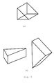
- a triple prism or a Porro prism can be used, as in the Fig. 5 in the partial images a) and b) are shown.
Landscapes
- Chemical & Material Sciences (AREA)
- Engineering & Computer Science (AREA)
- Physics & Mathematics (AREA)
- Electrochemistry (AREA)
- Chemical Kinetics & Catalysis (AREA)
- Organic Chemistry (AREA)
- Materials Engineering (AREA)
- Metallurgy (AREA)
- General Physics & Mathematics (AREA)
- Electromagnetism (AREA)
- Remote Sensing (AREA)
- Radar, Positioning & Navigation (AREA)
- Computer Networks & Wireless Communication (AREA)
- Mechanical Engineering (AREA)
- Length Measuring Devices By Optical Means (AREA)
- Electrical Discharge Machining, Electrochemical Machining, And Combined Machining (AREA)
Abstract
Description
- Die vorliegende Erfindung betrifft eine Vorrichtung bzw. ein Verfahren zur elektrochemischen Bearbeitung von Bauteilen mit mindestens einer Elektrode und mindestens einer Elektrodenhalterung, mit der die Elektrode bewegbar gelagert ist, sodass die Elektrode bei der elektrochemischen Bearbeitung bewegt werden kann.
- Das elektrochemische Bearbeiten von metallischen Bauteilen durch elektrochemisches Abtragen (electro chemical machining ECM) von Metall des Bauteils durch elektrochemisches Mikrofräsen (ICF), präzise elektrochemische Materialbearbeitung (PEM/PECM) bzw. Elektropolieren wird in vielen Industriebereichen eingesetzt. Bei der elektrochemischen Bearbeitung wird das Material durch anodische Oxidation in einer elektrochemischen Zelle abgetragen, bei der das Bauteil als Anode und eine Arbeitselektrode als Kathode geschaltet sind und ein geeigneter Elektrolyt zwischen Anode und Kathode angeordnet ist. Die Metallauflösung hängt ab von der Stromdichteverteilung im Elektrolyten und entsprechend vom Abstand der Elektrode vom zu bearbeitenden Bauteil. Folglich kann durch eine geeignet geformte Arbeitselektrode eine konturabhängige Auflösung des Metalls erzielt werden, sodass durch elektrochemische Bearbeitung exakte Oberflächenformen an dem zu bearbeitenden Bauteil eingestellt werden können.
- Zur genauen und präzisen Bearbeitung von Oberflächen kann sowohl die Spannung, die zwischen Kathode und Anode angelegt wird, gepulst angelegt werden, als auch die Elektrode oszilliert werden, um den Abstand zwischen zu bearbeitender Oberfläche und Arbeitselektrode zu verändern, um so den Austausch des Elektrolyten im Arbeitsspalt zu erleichtern.
- Um eine möglichst exakte Bearbeitung der Oberfläche des zu bearbeitenden Bauteils zu ermöglichen und insbesondere die vorgegebene Kontur des Bauteils möglichst genau und effektiv einzustellen, ist es erforderlich die elektrochemischen Bearbeitungsverfahren weiter zu verbessern.
- Es ist deshalb Aufgabe der vorliegenden Erfindung eine Vorrichtung sowie ein Verfahren zur elektrochemischen Bearbeitung von Bauteilen bereitzustellen, welches eine möglichst exakte und definierte Bearbeitung von metallischen Bauteilen ermöglicht, wobei die entsprechende Vorrichtung einfach aufgebaut und herzustellen sowie zu bedienen sein soll und das entsprechende Verfahren in gleicher Weise einfach durchführbar sein soll.
- Diese Aufgabe wird gelöst durch eine Vorrichtung mit den Merkmalen des Anspruchs 1 sowie ein Verfahren mit den Merkmalen des Anspruchs 12. Vorteilhafte Ausgestaltungen sind Gegenstand der abhängigen Ansprüche.
- Die vorliegende Erfindung geht aus von der Feststellung, dass zur exakten elektrochemischen Bearbeitung von metallischen Bauteilen der Abstand der Bearbeitungselektrode zu der zu bearbeitenden Oberfläche möglichst exakt eingestellt werden soll. Um eine exakte Einstellung des Arbeitsabstands der Arbeitselektrode zu dem zu bearbeitenden Bauteil zu ermöglichen, wird vorgeschlagen eine Positionsmessung zur Bestimmung der Position der Elektrode mit einem optischen Messsystem einzurichten, sodass zu jeder Zeit exakte Informationen über die Position der Elektrode und somit auch über den Abstand der Elektrode von der zu bearbeitenden Metalloberfläche bekannt sind.
- Die Verwendung eines optischen Messsystems ist hierfür vorteilhaft, da ein derartiges Messsystem berührungsfrei und damit verschleißfrei und ohne möglichen verfälschenden Einfluss auf die zu messende Komponente, also die Position der Elektrode, durchgeführt werden kann.
- Ein derartiges optisches Messsystem kann in einer einfachen Ausführungsform eine Lichtquelle und eine Erfassungseinrichtung umfassen, wobei durch die Lichtquelle ein Lichtstrahl auf die Erfassungseinrichtung ausgesendet wird und mit der Erfassungseinrichtung die Position des auftreffenden Lichtstrahls auf der Erfassungseinrichtung ermittelt werden kann. Ist entweder die Lichtquelle oder die Erfassungseinrichtung an der beweglichen Komponente, deren Position bestimmt werden soll, angeordnet, so lässt sich durch die positionsgenaue Erfassung des Lichtstrahls die Position der beweglichen Komponente bezüglich der unbeweglichen Komponente ermitteln.
- Bei der vorliegenden elektrochemischen Bearbeitung ist die Arbeitselektrode die bewegliche Komponente, die während der elektrochemischen Bearbeitung zur Positionierung der Arbeitselektrode gegenüber dem zu bearbeitenden Bauteil vor Beginn des elektrochemischen Abtragens bewegt wird oder während des elektrochemischen Abtragens zum Formen der Oberflächenkontur des zu bearbeitenden Bauteils nachgeführt wird. Darüber hinaus kann bei einem oszillierenden Betrieb die Elektrode auch Schwingbewegungen ausführen, um den Abstand der Arbeitselektrode von der zu bearbeitenden Oberfläche wiederholt zu verkleinern und zu vergrößern. Alle diese Bewegungen lassen sich durch ein optisches Messsystem zur Bestimmung der Position der Elektrode überwachen, also sowohl die anfängliche Positionierung der Elektrode gegenüber einem zu bearbeitenden Bauteil als auch die Nachführbewegung der Elektrode beim elektrochemischen Abtragen, wobei dieser Vorgang auch als Senken bezeichnet wird. Darüber hinaus kann eine Oszillationsbewegung der Elektrode während der chemischen Bearbeitung verfolgt und überwacht werden.
- Da die entsprechenden Bewegungen der Elektrode durch eine geeignete bewegliche Halterung der Elektrode ermöglicht werden, kann eine Komponente des optischen Messsystems, wie beispielsweise die Lichtquelle oder die Erfassungseinrichtung auch einer entsprechenden Halterung der Elektrode angeordnet sein, sodass mittelbar über die Bestimmung der Position der beweglichen Halterung auch die Position der Elektrode bestimmt werden kann.
- Bei einer entsprechend einfachen Ausführungsform mit einer Lichtquelle und einer Erfassungseinrichtung, wobei eine der Komponenten, also die Lichtquelle oder die Erfassungseinrichtung an der zu überwachenden, beweglichen Komponente angeordnet ist, also beispielsweise an der Elektrode oder der beweglichen Elektrodenhalterung, kann die andere Komponente des optischen Messsystems, also wiederum die Erfassungseinrichtung oder die Lichtquelle an einem ortsfesten Träger angeordnet sein, sodass die relative Positionierung einer beweglichen Komponente des optischen Messsystems, also der Lichtquelle oder der Erfassungseinrichtung, in Bezug auf die andere, ortsfeste Komponente des optischen Messsystems, also die Erfassungseinrichtung oder die Lichtquelle, zur Positionsbestimmung Verwendung findet.
- Bei einer weiteren Ausführungsform können sowohl die Lichtquelle als auch die Erfassungseinrichtung ortsfest an einem Träger angeordnet sein, um zu vermeiden, dass die entsprechende elektronische Komponente, wie die Lichtquelle oder die Erfassungseinrichtung, aufwändig auf einem bewegbaren Teil angeordnet werden müssen. Außerdem hat die ortsfeste Lagerung der Lichtquelle und der Erfassungseinrichtung den Vorteil, dass die entsprechenden elektrischen Komponenten, die sehr empfindlich sein können, nicht einer ständigen Bewegung ausgesetzt sind. In diesem Fall kann an der beweglichen Komponente, deren Position bestimmt werden soll, wie im vorliegenden Fall der Arbeitselektrode oder der Elektrodenhalterung eine Umlenkoptik angeordnet sein, die den Lichtstrahl der Lichtquelle auf die Erfassungseinrichtung umlenkt, sodass der Lichtstrahl zunächst von der Lichtquelle am ortsfesten Träger ausgesandt, durch die Umlenkoptik an der beweglichen Elektrode bzw. der beweglichen Elektrodenhalterung umgelenkt bzw. reflektiert wird, um anschließend in der ortsfesten Erfassungseinrichtung erfasst zu werden, wo wiederum der Auftreffort des Lichtstrahls zur Positionsbestimmung der beweglichen Elektrode oder der beweglichen Elektrodenhalterung Verwendung findet. Entsprechend muss die Umlenkoptik eine positionsgetreue Reflexion bzw. Umlenkung des von der Lichtquelle auftreffenden Lichtstrahls zur Erfassungseinrichtung bewirken. Hierzu kann ein sogenannter Retroreflektor eingesetzt werden, welcher den auftreffenden Lichtstrahl parallel zum auftreffenden Lichtstrahl und lediglich parallel versetzt zum auftreffenden Lichtstrahl reflektiert. Ein derartiger Retroreflektor kann durch einen Tripelspiegel, ein Tripelprisma oder ein Porroprisma gebildet sein.
- Die Erfassungseinrichtung kann einen positionsempfindlichen Sensor wie einen PSD - (position sensitive device) Sensor oder einen CCD - (charge coupled device) Sensor umfassen. Mit diesen Sensoren ist eine Bestimmung der Auftreffposition des auftreffenden Lichtstrahl auf dem Sensor möglich, wobei die ermittelten Messsignale in einer entsprechend eingerichteten elektronischen Datenverarbeitungsanlage automatisch verarbeitet und ausgewertet werden können.
- Die optische Messeinrichtung kann als Lichtquelle einen Laser umfassen, der einen exakt definierten Lichtstrahl erzeugt. Darüber hinaus kann eine Fokussieroptik, wie beispielsweise eine Fokussierlinse eingesetzt werden, um den Lichtstrahl weiter zu fokussieren. Vor der Erfassungseinrichtung kann eine Filtereinrichtung vorgesehen sein, um unerwünschte Störsignale zu vermeiden.
- Zum Schutz der empfindlichen elektronischen Geräte, wie der Lichtquelle oder der Sensoren der Erfassungseinrichtung, kann die optische Messeinrichtung mit einer Schutzhülle, wie beispielsweise einem Faltenbalg versehen sein oder es kann ein Sperrluftsystem angeordnet sein, welches durch Erzeugen eines Sperrluftstroms das Eindringen von unerwünschten Fremdstoffen, wie beispielsweise Dämpfe des Elektrolyten und dergleichen verhindert.
- Die Elektrode ist üblicherweise so gelagert, dass die Elektrode eine zweidimensionale Bewegung durchführen kann, wobei allerdings auch dreidimensionale Bewegungen, also Bewegungen in drei unabhängigen Raumrichtungen möglich sein können. Insgesamt kann die Bewegung der Elektrode bis zu sechs Bewegungsfreiheitsgrade umfassen. Entsprechend kann auch das optische Messsystem so hergerichtet sein, dass es eine zweidimensionale oder dreidimensionale Bewegung der Elektrode erfassen kann. Insbesondere kann das optische Messsystem mehrere der oben beschriebenen Komponenten wie Lichtquellen und Erfassungseinrichtungen aufweisen oder es können mehrere optische Messsysteme so angeordnet sein, dass sämtliche Bewegungen der Elektrode erfassbar sind, beispielsweise indem zwei optische Messsysteme gedreht um 90° zueinander angeordnet sind.
- Mit dem optischen Messsystem kann die Position der beweglichen Elektrode ständig während und/oder vor und/oder nach der Bearbeitung erfasst werden, insbesondere auch bei einem oszillierenden Betrieb, also wenn die Elektrode oszillierend bewegt wird. Insbesondere können durch das optische Messsystem hohe Abtastraten im Bereich von 500 Hz bis 1 kHz realisiert werden, sodass mechanische Oszillationen der Elektrode im Bereich von 20 bis 50 Hz erfasst werden können. Die Position der Elektrode kann hierbei auf 5 µm, insbesondere 1 µm und vorzugsweise 0,5 µm genau bestimmt werden, wobei Bewegungen im Bereich von mehreren Millimetern erfasst werden können.
- Die beigefügten Zeichnungen zeigen in rein schematischer Weise in
- Fig. 1
- eine Darstellung einer Elektrodenhalterung zur beweglichen Halterung einer Elektrode;
- Fig. 2
- eine Darstellung einer erfindungsgemäßen Elektrodenhalterung mit einem optischen Messsystem zur Positionsbestimmung der Elektrode;
- Fig. 3
- eine Ansicht der Elektrodenhalterung aus
Fig. 2 um 90° gedreht; - Fig. 4
- eine Darstellung des optischen Messsystems; und in
- Fig. 5
- in den Teilbildern a) und b) eine Darstellung eines Tripelprismas und eines Porroprismas.
- Die
Fig. 1 zeigt eine rein schematische Darstellung einer Elektrodenhalterung 1 zur beweglichen Lagerung einer Elektrode mit einer feststehenden Basis 2 und einer an biegbaren Blechen 3a,3b angeordnete Parallelschwinge 4, die sich gemäß dem Doppelpfeil hin und her bewegen kann und die in einer ersten Raumrichtung eine Verschiebung V ausführt und gleichzeitig eine Höhenänderung H in einer zur ersten Raumrichtung quer stehenden Raumrichtung verursacht, sodass eine an der Parallelschwinge 4 angeordnete Elektrode eine zweidimensionale Bewegung in zwei unabhängigen Raumrichtungen ausführt, wie durch die gestrichelte Darstellung gezeigt ist. Obwohl in derFig. 1 die Bewegung der Parallelschwinge 4 als eine kombinierte Bewegung in den beiden unabhängigen Raumrichtungen dargestellt ist, kann eine entsprechende Elektrodenhalterung auch so ausgeführt sein, dass die Elektrodenhalterung unabhängige Bewegungen in den beiden unabhängigen Raumrichtungen ausführen kann, sodass beliebige zweidimensionale Bewegungen durchgeführt werden können. - Die
Fig. 2 zeigt die Elektrodenhalterung ausFig. 1 in einer Seitenansicht mit einer Bearbeitungselektrode 5 und dem erfindungsgemäßen optischen Messsystem zur Bestimmung der Position der Bearbeitungselektrode 5. Die Bearbeitungselektrode 5 ist auf der Parallelschwinge 4 und über die bewegliche Halterung 3a an der Basis 2 angeordnet. Beabstandet von der beweglichen Halterung 3a und entkoppelt von der Bewegung der beweglichen Halterung 3a ist ein Sockel 6 vorgesehen, auf welchem eine Lichtquellen - und Erfassungseinrichtungseinheit 7 angeordnet ist, die berührungslos mit einem Tripelspiegel 8 zusammenwirkt, der an der Parallelschwinge 4 angeordnet ist. Die Lichtquellen - und Erfassungseinrichtungseinheit 7 des optischen Messsystems umfasst einen Laser, welcher gemäß den Pfeilen inFig. 2 einen Laserstrahl in Richtung des Tripelspiegels 8 aussendet, wobei der Laserstrahl am Tripelspiegel 8 parallel versetzt reflektiert wird und von einem Sensor der Lichtquellen - und Erfassungseinrichtungseinheit 7 erfasst wird. Bei dem Sensor handelt es sich um einen positionssensitiven Sensor, wie sogenannte PSD (positioning sensitive device) - oder CCD (CCD charge coupled device) - Sensoren. Durch den positionssensitiven Sensor kann die Position des vom Tripelspiegel 8 reflektierten Laserstrahls ermittelt werden, die wiederum von der Position des Tripelspiegels 8 und somit von der Position der Parallelschwinge 4 sowie der Bearbeitungselektrode 5 abhängt, da der Tripelspiegel 8 als sogenannter Retroreflektor eine positionsgetreue Reflexion des von dem Laser ausgestrahlten Laserstrahls bewirkt. - Um eine Verschmutzung des optischen Messsystems bzw. seiner Komponenten zu vermeiden, ist ein Faltenbalg 16 vorgesehen, der den Zwischenraum zwischen Lichtquelle, Sensoren und Umlenkoptik abschließt. Zusätzlich oder alternativ kann ein Sperrluftsystem mit einem gemäß dem Pfeil 17 zugeführten Strom an Luft oder sonstigen geeigneten Gasen aufgebaut werden, welches das Eindringen von Verschmutzungen und Verunreinigungen verhindern kann.
- Die
Fig. 3 zeigt eine um 90° gedrehte Ansicht der Elektrodenhalterung mit der Parallelschwinge 4, der Elektrode 5, dem Tripelspiegel 8 in der Parallelschwinge 4 und den beweglichen Halterungen 3a, 3b die beispielsweise durch biegbare Bleche gebildet sein können. - Wie durch den Doppelpfeil 18 der
Fig. 3 angezeigt ist, kann sich die Elektrode 5 mit der Parallelschwinge 4 entlang einer bogenförmigen Linie zweidimensional hin und herbewegen, wobei der in der Parallelschwinge 4 angebrachte Tripelspiegel 8 eine identische Bewegung ausführt. Da der von dem Tripelspiegel 8 reflektierte Laserstrahl der Position des Tripelspiegels bzw. der Parallelschwinge 4 und somit der Elektrode 5 entspricht, kann durch Ermittlung der Position des Laserstrahls durch einen positionsempfindlichen Sensor, wie beispielsweise einen PSD - oder CCD - Sensor die exakte Lage bzw. Position der Elektrode 5 bestimmt werden. - Für eine vollautomatische Auswertung der Sensorsignale, kann der Sensor über einen Messverstärker und sonstige erforderliche elektronische Zusatzkomponenten, insbesondere über konventionelle Schnittstellen, wie beispielsweise USB-Schnittstellen, mit einem Computer verbunden sein, auf den für die Auswertung der Sensorsignale geeignete Software zum Einsatz kommt. Über die elektronische Datenverarbeitungsanlage können entsprechende Messsignale auch gespeichert und hinsichtlich zeitlicher Änderungen ausgewertet werden. Damit ist auch eine Langzeitkontrolle der Anlage möglich.
- Anstelle nur eines optischen Messsystems 7, 8 für eine bewegliche Elektrodenhalterung 1 können auch mehrere optische Messsysteme bzw. mehrere Lichtquellen wie Laser, optische Umlenkeinheiten, wie Tripelspiegel, und Sensoren an einer Elektrodenhalterung 1 vorgesehen werden, um beispielsweise mittels einer zweiten optischen Messeinheit zweidimensionale Bewegungen quer, insbesondere senkrecht zu der ersten zweidimensionalen Bewegung erfasst zu können. Beispielsweise könnte bei der Elektrodenhalterung 1, wie sie in der
Fig. 2 gezeigt ist, ein weiterer Tripelspiegel 8 zur Reflexion eines Laserstrahls, der sich senkrecht zur Blattebene erstreckt, vorgesehen sein, um Bewegungen der Bearbeitungselektrode 5 in der Darstellung derFig. 2 nach links oder rechts bzw. nach oben und unten erfassen zu können. - Die
Fig. 4 verdeutlicht das optische Messsystem mit der Lichtquellen - und Erfassungseinrichtungseinheit 7 sowie dem Tripelspiegel 8. Die Lichtquellen - und Erfassungseinrichtungseinheit 7 umfasst einen Laser 9, dem eine Fokussierlinse 10 vorgeschaltet ist. Der fokussierte Laserstrahl trifft auf den Tripelspiegel 8, wo der Laserstrahl parallel versetzt reflektiert wird um über einen Filter 12 auf einen positionsempfindlichen Sensor 11, wie beispielsweise einen PSD - oder CCD - Sensor zu treffen. Der Filter 12 dient zur Unterdrückung von Rauscheffekten bzw. zum Herausfiltern störender Lichtsignale. - Der Tripelspiegel 8 weist drei senkrecht zueinander stehende Spiegelflächen 13, 14, 15 auf, die für eine Retroreflexion mit einem zum einfallenden Laserstrahl parallel versetzten Reflexionsstrahl sorgen, sodass die Lichtquelle in Form des Lasers 9 und der Sensor 11 separat von der beweglichen Elektrodenhalterung an einem ortsfesten Sockel angeordnet sein können, um eine berührungslose Positionsbestimmung mittels des optischen Messsystems zu ermöglichen. Statt des Tripelspiegels 8 können auch ein Tripelprisma oder ein Porroprisma eingesetzt werden, wie sie in der
Fig. 5 in den Teilbildern a) und b) dargestellt sind. - Obwohl die vorliegende Erfindung anhand der beigefügten Ausführungsbeispiele detailliert beschrieben worden ist, ist für den Fachmann selbstverständlich, dass die Erfindung nicht auf diese Ausführungsbeispiele beschränkt ist, sondern dass Abwandlungen in der Weise möglich sind, dass einzelne Merkmale weggelassen oder andersartige Kombinationen von Merkmalen verwirklicht werden können, solange der Schutzbereich der beigefügten Ansprüche nicht verlassen wird. Insbesondere umfasst die Offenbarung der vorliegenden Erfindung sämtliche Kombinationen der vorgestellten Einzelmerkmale.
Claims (16)
- Vorrichtung zur elektrochemischen Bearbeitung von Bauteilen mit mindestens einer Elektrode (5) und mindestens einer Elektrodenhalterung (1,2,3a,3b,4), mit der die Elektrode bewegbar gelagert ist,
dadurch gekennzeichnet, dass
die Vorrichtung mindestens ein optisches Messsystem (7,8) zur Bestimmung der Position der Elektrode umfasst. - Vorrichtung nach Anspruch 1,
dadurch gekennzeichnet, dass
das optische Messsystem eine Lichtquelle (9) und eine Erfassungseinrichtung (11) umfasst. - Vorrichtung nach Anspruch 2,
dadurch gekennzeichnet, dass
die Lichtquelle (9) oder die Erfassungseinrichtung (11) an der Elektrode oder der Halterung angeordnet sind. - Vorrichtung nach Anspruch 2,
dadurch gekennzeichnet, dass
die Lichtquelle (9) oder die Erfassungseinrichtung (11) an einem ortsfesten Träger (6) angeordnet sind. - Vorrichtung nach Anspruch 2,
dadurch gekennzeichnet, dass
das optische Messystem eine Umlenkoptik (8) umfasst, die das Licht der Lichtquelle positionsgetreu auf die Erfassungseinrichtung umlenkt, wobei die Umlenkoptik an der Halterung oder der Elektrode angeordnet ist und die Lichtquelle und Erfassungseinrichtung an mindestens einem ortsfesten Träger (6) angeordnet sind. - Vorrichtung nach Anspruch 5,
dadurch gekennzeichnet, dass
die Umlenkoptik einen Retroreflektor, insbesondere einen Tripelspiegel (8), ein Tripelprisma oder ein Porroprisma umfasst. - Vorrichtung nach einem der Ansprüche 2 bis 6,
dadurch gekennzeichnet, dass
die Erfassungseinrichtung (11) einen positionsempfindlichen Sensor (PSD (position sensitive device) - Sensor) oder einen CCD - Sensor (CCD charge coupled device) umfasst. - Vorrichtung nach einem der Ansprüche 2 bis 7,
dadurch gekennzeichnet, dass
die optische Messeinrichtung einen Laser (9) und/oder eine Fokussieroptik (10) und/oder eine Filtereinrichtung (12) umfasst. - Vorrichtung nach einem der vorhergehenden Ansprüche,
dadurch gekennzeichnet, dass
die optische Messeinrichtung eine Schutzhülle, insbesondere einen Faltenbalg (16) und/oder ein Sperrluftsystem (17) umfasst. - Vorrichtung nach einem der vorhergehenden Ansprüche,
dadurch gekennzeichnet, dass
die Halterung (1,2,3a,3b,4) so hergerichtet ist, dass eine zwei - dimensionale und/oder drei - dimensionale Bewegung der Elektrode ermöglicht wird. - Vorrichtung nach einem der vorhergehenden Ansprüche,
dadurch gekennzeichnet, dass
das optische Messsystem so hergerichtet ist, dass eine zwei - dimensionale und/oder drei - dimensionale Bewegung der Elektrode erfassbar ist. - Verfahren zur elektrochemischen Bearbeitung von Bauteilen, insbesondere mit einer Vorrichtung nach einem der vorhergehenden Ansprüche, bei welchem die Elektrode (5) während der elektrochemischen Bearbeitung bewegt wird,
dadurch gekennzeichnet, dass
die Position der Elektrode (5) mittels eines optischen Messsystems (7,8) erfasst wird. - Verfahren nach Anspruch 12,
dadurch gekennzeichnet, dass
die Position ständig während der Bearbeitung und/oder vor und/oder nach der Bearbeitung erfasst wird. - Verfahren nach Anspruch 12 oder 13,
dadurch gekennzeichnet, dass
die Position auf 5 µm, insbesondere 1 µm, vorzugsweise 0,5 µm genau erfasst wird. - Verfahren nach einem der vorhergehenden Ansprüche 12 bis 14,
dadurch gekennzeichnet, dass
die Elektrode (5) oszillierend bewegt wird. - Verfahren nach einem der vorhergehenden Ansprüche 12 bis 15,
dadurch gekennzeichnet, dass
die elektrochemische Bearbeitung gepulst erfolgt.
Applications Claiming Priority (1)
| Application Number | Priority Date | Filing Date | Title |
|---|---|---|---|
| DE102013214228.5A DE102013214228A1 (de) | 2013-07-19 | 2013-07-19 | Optisches Messsytem zur Positionsbestimmung einer Elektrode bei der elektrochemischen Bearbeitung von Bauteilen |
Publications (2)
| Publication Number | Publication Date |
|---|---|
| EP2826583A1 true EP2826583A1 (de) | 2015-01-21 |
| EP2826583B1 EP2826583B1 (de) | 2018-06-13 |
Family
ID=51210265
Family Applications (1)
| Application Number | Title | Priority Date | Filing Date |
|---|---|---|---|
| EP14176127.0A Not-in-force EP2826583B1 (de) | 2013-07-19 | 2014-07-08 | Optisches Messsytem zur Positionsbestimmung einer Elektrode bei der elektrochemischen Bearbeitung von Bauteilen und entsprechendes Verfahren |
Country Status (3)
| Country | Link |
|---|---|
| US (1) | US9822462B2 (de) |
| EP (1) | EP2826583B1 (de) |
| DE (1) | DE102013214228A1 (de) |
Families Citing this family (2)
| Publication number | Priority date | Publication date | Assignee | Title |
|---|---|---|---|---|
| DE102014218169B4 (de) * | 2014-09-11 | 2022-01-20 | MTU Aero Engines AG | Elektrochemische Bearbeitung eines Werkstücks |
| CN110988892B (zh) * | 2019-12-09 | 2022-04-26 | 北京信息科技大学 | 一种激光主动探测系统 |
Citations (5)
| Publication number | Priority date | Publication date | Assignee | Title |
|---|---|---|---|---|
| DE19617880A1 (de) * | 1995-04-28 | 1996-10-31 | Giddings & Lewis | Abstandsmeßvorrichtung |
| DE10122321A1 (de) * | 2000-05-09 | 2002-04-11 | Busch Dieter & Co Prueftech | Vorrichtung zur quantitativen Beurteilung der fluchtenden Lage zweier Maschinenteile, Werkstücke oder dergleichen |
| US20070239311A1 (en) * | 2006-03-30 | 2007-10-11 | Ugs Corp. | A Method for Under-sizing Electrodes for Polygonal Orbit Electric Discharge Machining |
| EP2181791A2 (de) * | 2008-10-28 | 2010-05-05 | Agie Sa | Maschine zur Funkenerosionsverarbeitung und Positionierungsverfahren für diese Maschine |
| DE102011106928A1 (de) * | 2011-07-08 | 2013-01-10 | Admedes Schuessler Gmbh | Verfahren und Vorrichtung zum elektrochemischen Abtragen eines Werkstoffs |
Family Cites Families (7)
| Publication number | Priority date | Publication date | Assignee | Title |
|---|---|---|---|---|
| CH625447A5 (de) * | 1978-03-06 | 1981-09-30 | Agie Ag Ind Elektronik | |
| JPS60159716A (ja) * | 1984-01-31 | 1985-08-21 | Sakai Tokushu Camera Seisakusho:Kk | じゃばら |
| DE4243393C2 (de) * | 1992-12-21 | 1995-04-06 | Agie Ag Ind Elektronik | Vorrichtung und Verfahren zum elektroerosiven Schneiden |
| JP3192992B2 (ja) | 1996-08-27 | 2001-07-30 | 株式会社東京精密 | 工作機械の角度割出精度測定方法及びシステム |
| GB9925024D0 (en) * | 1999-10-23 | 1999-12-22 | Ultra Systems Limited | Electrochemical machining |
| DE502006002379D1 (de) * | 2006-04-27 | 2009-01-29 | 3R Syst Int Ab | Spannvorrichtung mit Einrichtung zur Messung der Distanz zwischen einem Spannfutter und einem Werkzeug- oder Werkstückhalter |
| TW201034779A (en) * | 2009-03-27 | 2010-10-01 | Univ Nat Central | Apparatus and method for magnetic field assisted electrochemical discharge machining |
-
2013
- 2013-07-19 DE DE102013214228.5A patent/DE102013214228A1/de not_active Withdrawn
-
2014
- 2014-07-08 EP EP14176127.0A patent/EP2826583B1/de not_active Not-in-force
- 2014-07-17 US US14/333,611 patent/US9822462B2/en not_active Expired - Fee Related
Patent Citations (5)
| Publication number | Priority date | Publication date | Assignee | Title |
|---|---|---|---|---|
| DE19617880A1 (de) * | 1995-04-28 | 1996-10-31 | Giddings & Lewis | Abstandsmeßvorrichtung |
| DE10122321A1 (de) * | 2000-05-09 | 2002-04-11 | Busch Dieter & Co Prueftech | Vorrichtung zur quantitativen Beurteilung der fluchtenden Lage zweier Maschinenteile, Werkstücke oder dergleichen |
| US20070239311A1 (en) * | 2006-03-30 | 2007-10-11 | Ugs Corp. | A Method for Under-sizing Electrodes for Polygonal Orbit Electric Discharge Machining |
| EP2181791A2 (de) * | 2008-10-28 | 2010-05-05 | Agie Sa | Maschine zur Funkenerosionsverarbeitung und Positionierungsverfahren für diese Maschine |
| DE102011106928A1 (de) * | 2011-07-08 | 2013-01-10 | Admedes Schuessler Gmbh | Verfahren und Vorrichtung zum elektrochemischen Abtragen eines Werkstoffs |
Also Published As
| Publication number | Publication date |
|---|---|
| EP2826583B1 (de) | 2018-06-13 |
| US9822462B2 (en) | 2017-11-21 |
| US20150021199A1 (en) | 2015-01-22 |
| DE102013214228A1 (de) | 2015-02-19 |
Similar Documents
| Publication | Publication Date | Title |
|---|---|---|
| DE102017117413B4 (de) | Verfahren zur optischen Messung der Einschweißtiefe | |
| EP1097022B1 (de) | Verfahren und anordnung zum kalibrieren einer laserbearbeitungsmaschine zum bearbeiten von werkstücken | |
| DE102018219129B3 (de) | Verfahren und Computerprogrammprodukt zur OCT-Messstrahljustierung | |
| DE69127121T3 (de) | Vorrichtung und Verfahren zum automatischen Ausrichten einer Schweissvorrichtung zum Stumpfschweissen von Werkstücken | |
| DE102007016444B4 (de) | Bearbeitungseinrichtung | |
| DE102008049821B4 (de) | Abstandssensor und Verfahren zur Ermittlung eines Abstands und/oder von Abstandsschwankungen zwischen einem Bearbeitungslaser und einem Werkstück | |
| EP3140609B1 (de) | Vorrichtung zur messung der tiefe einer schweissnaht in echtzeit | |
| EP3463741B1 (de) | Vorrichtung zur prozessüberwachung bei der laserbearbeitung mit einer optischen abstandmessvorrichtung und einer prismen-ablenkeinheit ; laserbearbeitungskopf mit einer solchen vorrichtung | |
| EP1904260B1 (de) | Verfahren und vorrichtung zur bestimmung einer lateralen relativbewegung zwischen einem bearbeitungskopf und einem werkstück | |
| DE10297255B4 (de) | Verfahren und Vorrichtung zum Überwachen und Einstellen eines Laserschweißprozesses | |
| DE102017126867A1 (de) | Laserbearbeitungssystem und Verfahren zur Laserbearbeitung | |
| DE102016001661B3 (de) | Messvorrichtung und Verfahren zum Ermitteln einer relativen Neigung eines Werkstücks mittels optischer Kohärenztomographie bei einer Bearbeitung | |
| EP3838472A1 (de) | Ablenkeinheit mit zwei fenstern, einem optischen element und einer xy-ablenkvorrichtung | |
| DE2164397C3 (de) | Optoelektrische Spurvorrichtung | |
| DE102013015656A1 (de) | Verfahren zum Messen der Eindringtiefe eines Laserstrahls in ein Werkstück, Verfahren zum Bearbeiten eines Werkstücks sowie Laserbearbeitungsvorrichtung | |
| EP3154740B1 (de) | Vorrichtung zur lasermaterialbearbeitung mit einer parallel-versatz-einheit | |
| DE19852302A1 (de) | Verfahren und Vorrichtung zum Bearbeiten von Werkstücken mit Hochenergiestrahlung | |
| DE102022118147A1 (de) | Laserbearbeitungskopf und Verfahren zum Bearbeiten eines Werkstücks | |
| DE4106008A1 (de) | Verfahren zur on-line-ueberwachung bei der werkstueckbearbeitung mit laserstrahlung | |
| DE102008016340B3 (de) | Verfahren und Vorrichtung zur Bearbeitung einer Leiterplatte | |
| WO2023198765A1 (de) | Laserbearbeitungsvorrichtung | |
| EP2826583B1 (de) | Optisches Messsytem zur Positionsbestimmung einer Elektrode bei der elektrochemischen Bearbeitung von Bauteilen und entsprechendes Verfahren | |
| EP0128993B1 (de) | Verfahren zum Feststellen von Referenzdaten zum Zwecke der Korrektur von mechanischen Bewegungen beim Schreiben von Linien mit einem Schreiblaserstrahl in einem metallisierten Raster und Vorrichtung zur Durchführung des Verfahrens | |
| WO1986005895A1 (fr) | Agencement d'alignement, de controle et/ou de mesure d'objets bidimensionnels | |
| DE102023127963A1 (de) | Verfahren und Vorrichtung zum Ausbilden einer Struktur an einem Werkstück mittels Bearbeitungsstrahlung |
Legal Events
| Date | Code | Title | Description |
|---|---|---|---|
| 17P | Request for examination filed |
Effective date: 20140708 |
|
| AK | Designated contracting states |
Kind code of ref document: A1 Designated state(s): AL AT BE BG CH CY CZ DE DK EE ES FI FR GB GR HR HU IE IS IT LI LT LU LV MC MK MT NL NO PL PT RO RS SE SI SK SM TR |
|
| AX | Request for extension of the european patent |
Extension state: BA ME |
|
| PUAI | Public reference made under article 153(3) epc to a published international application that has entered the european phase |
Free format text: ORIGINAL CODE: 0009012 |
|
| R17P | Request for examination filed (corrected) |
Effective date: 20150611 |
|
| RBV | Designated contracting states (corrected) |
Designated state(s): AL AT BE BG CH CY CZ DE DK EE ES FI FR GB GR HR HU IE IS IT LI LT LU LV MC MK MT NL NO PL PT RO RS SE SI SK SM TR |
|
| 17Q | First examination report despatched |
Effective date: 20161110 |
|
| GRAP | Despatch of communication of intention to grant a patent |
Free format text: ORIGINAL CODE: EPIDOSNIGR1 |
|
| RIC1 | Information provided on ipc code assigned before grant |
Ipc: G01B 11/02 20060101ALN20180328BHEP Ipc: B23H 3/00 20060101ALN20180328BHEP Ipc: G01B 11/04 20060101ALI20180328BHEP Ipc: B23H 7/26 20060101AFI20180328BHEP |
|
| GRAS | Grant fee paid |
Free format text: ORIGINAL CODE: EPIDOSNIGR3 |
|
| INTG | Intention to grant announced |
Effective date: 20180412 |
|
| GRAA | (expected) grant |
Free format text: ORIGINAL CODE: 0009210 |
|
| AK | Designated contracting states |
Kind code of ref document: B1 Designated state(s): AL AT BE BG CH CY CZ DE DK EE ES FI FR GB GR HR HU IE IS IT LI LT LU LV MC MK MT NL NO PL PT RO RS SE SI SK SM TR |
|
| REG | Reference to a national code |
Ref country code: GB Ref legal event code: FG4D Free format text: NOT ENGLISH |
|
| REG | Reference to a national code |
Ref country code: CH Ref legal event code: EP Ref country code: AT Ref legal event code: REF Ref document number: 1007959 Country of ref document: AT Kind code of ref document: T Effective date: 20180615 |
|
| REG | Reference to a national code |
Ref country code: DE Ref legal event code: R096 Ref document number: 502014008517 Country of ref document: DE |
|
| REG | Reference to a national code |
Ref country code: IE Ref legal event code: FG4D Free format text: LANGUAGE OF EP DOCUMENT: GERMAN |
|
| REG | Reference to a national code |
Ref country code: FR Ref legal event code: PLFP Year of fee payment: 5 |
|
| REG | Reference to a national code |
Ref country code: NL Ref legal event code: MP Effective date: 20180613 |
|
| REG | Reference to a national code |
Ref country code: LT Ref legal event code: MG4D |
|
| PG25 | Lapsed in a contracting state [announced via postgrant information from national office to epo] |
Ref country code: NO Free format text: LAPSE BECAUSE OF FAILURE TO SUBMIT A TRANSLATION OF THE DESCRIPTION OR TO PAY THE FEE WITHIN THE PRESCRIBED TIME-LIMIT Effective date: 20180913 Ref country code: FI Free format text: LAPSE BECAUSE OF FAILURE TO SUBMIT A TRANSLATION OF THE DESCRIPTION OR TO PAY THE FEE WITHIN THE PRESCRIBED TIME-LIMIT Effective date: 20180613 Ref country code: BG Free format text: LAPSE BECAUSE OF FAILURE TO SUBMIT A TRANSLATION OF THE DESCRIPTION OR TO PAY THE FEE WITHIN THE PRESCRIBED TIME-LIMIT Effective date: 20180913 Ref country code: SE Free format text: LAPSE BECAUSE OF FAILURE TO SUBMIT A TRANSLATION OF THE DESCRIPTION OR TO PAY THE FEE WITHIN THE PRESCRIBED TIME-LIMIT Effective date: 20180613 Ref country code: CY Free format text: LAPSE BECAUSE OF FAILURE TO SUBMIT A TRANSLATION OF THE DESCRIPTION OR TO PAY THE FEE WITHIN THE PRESCRIBED TIME-LIMIT Effective date: 20180613 Ref country code: LT Free format text: LAPSE BECAUSE OF FAILURE TO SUBMIT A TRANSLATION OF THE DESCRIPTION OR TO PAY THE FEE WITHIN THE PRESCRIBED TIME-LIMIT Effective date: 20180613 Ref country code: ES Free format text: LAPSE BECAUSE OF FAILURE TO SUBMIT A TRANSLATION OF THE DESCRIPTION OR TO PAY THE FEE WITHIN THE PRESCRIBED TIME-LIMIT Effective date: 20180613 |
|
| PG25 | Lapsed in a contracting state [announced via postgrant information from national office to epo] |
Ref country code: HR Free format text: LAPSE BECAUSE OF FAILURE TO SUBMIT A TRANSLATION OF THE DESCRIPTION OR TO PAY THE FEE WITHIN THE PRESCRIBED TIME-LIMIT Effective date: 20180613 Ref country code: LV Free format text: LAPSE BECAUSE OF FAILURE TO SUBMIT A TRANSLATION OF THE DESCRIPTION OR TO PAY THE FEE WITHIN THE PRESCRIBED TIME-LIMIT Effective date: 20180613 Ref country code: GR Free format text: LAPSE BECAUSE OF FAILURE TO SUBMIT A TRANSLATION OF THE DESCRIPTION OR TO PAY THE FEE WITHIN THE PRESCRIBED TIME-LIMIT Effective date: 20180914 Ref country code: RS Free format text: LAPSE BECAUSE OF FAILURE TO SUBMIT A TRANSLATION OF THE DESCRIPTION OR TO PAY THE FEE WITHIN THE PRESCRIBED TIME-LIMIT Effective date: 20180613 |
|
| PG25 | Lapsed in a contracting state [announced via postgrant information from national office to epo] |
Ref country code: NL Free format text: LAPSE BECAUSE OF FAILURE TO SUBMIT A TRANSLATION OF THE DESCRIPTION OR TO PAY THE FEE WITHIN THE PRESCRIBED TIME-LIMIT Effective date: 20180613 |
|
| PG25 | Lapsed in a contracting state [announced via postgrant information from national office to epo] |
Ref country code: EE Free format text: LAPSE BECAUSE OF FAILURE TO SUBMIT A TRANSLATION OF THE DESCRIPTION OR TO PAY THE FEE WITHIN THE PRESCRIBED TIME-LIMIT Effective date: 20180613 Ref country code: PL Free format text: LAPSE BECAUSE OF FAILURE TO SUBMIT A TRANSLATION OF THE DESCRIPTION OR TO PAY THE FEE WITHIN THE PRESCRIBED TIME-LIMIT Effective date: 20180613 Ref country code: IS Free format text: LAPSE BECAUSE OF FAILURE TO SUBMIT A TRANSLATION OF THE DESCRIPTION OR TO PAY THE FEE WITHIN THE PRESCRIBED TIME-LIMIT Effective date: 20181013 Ref country code: CZ Free format text: LAPSE BECAUSE OF FAILURE TO SUBMIT A TRANSLATION OF THE DESCRIPTION OR TO PAY THE FEE WITHIN THE PRESCRIBED TIME-LIMIT Effective date: 20180613 Ref country code: RO Free format text: LAPSE BECAUSE OF FAILURE TO SUBMIT A TRANSLATION OF THE DESCRIPTION OR TO PAY THE FEE WITHIN THE PRESCRIBED TIME-LIMIT Effective date: 20180613 Ref country code: SK Free format text: LAPSE BECAUSE OF FAILURE TO SUBMIT A TRANSLATION OF THE DESCRIPTION OR TO PAY THE FEE WITHIN THE PRESCRIBED TIME-LIMIT Effective date: 20180613 |
|
| PG25 | Lapsed in a contracting state [announced via postgrant information from national office to epo] |
Ref country code: IT Free format text: LAPSE BECAUSE OF FAILURE TO SUBMIT A TRANSLATION OF THE DESCRIPTION OR TO PAY THE FEE WITHIN THE PRESCRIBED TIME-LIMIT Effective date: 20180613 Ref country code: SM Free format text: LAPSE BECAUSE OF FAILURE TO SUBMIT A TRANSLATION OF THE DESCRIPTION OR TO PAY THE FEE WITHIN THE PRESCRIBED TIME-LIMIT Effective date: 20180613 |
|
| REG | Reference to a national code |
Ref country code: CH Ref legal event code: PL |
|
| REG | Reference to a national code |
Ref country code: DE Ref legal event code: R097 Ref document number: 502014008517 Country of ref document: DE |
|
| PG25 | Lapsed in a contracting state [announced via postgrant information from national office to epo] |
Ref country code: MC Free format text: LAPSE BECAUSE OF FAILURE TO SUBMIT A TRANSLATION OF THE DESCRIPTION OR TO PAY THE FEE WITHIN THE PRESCRIBED TIME-LIMIT Effective date: 20180613 Ref country code: LU Free format text: LAPSE BECAUSE OF NON-PAYMENT OF DUE FEES Effective date: 20180708 |
|
| REG | Reference to a national code |
Ref country code: BE Ref legal event code: MM Effective date: 20180731 |
|
| REG | Reference to a national code |
Ref country code: IE Ref legal event code: MM4A |
|
| PLBE | No opposition filed within time limit |
Free format text: ORIGINAL CODE: 0009261 |
|
| STAA | Information on the status of an ep patent application or granted ep patent |
Free format text: STATUS: NO OPPOSITION FILED WITHIN TIME LIMIT |
|
| PG25 | Lapsed in a contracting state [announced via postgrant information from national office to epo] |
Ref country code: IE Free format text: LAPSE BECAUSE OF NON-PAYMENT OF DUE FEES Effective date: 20180708 Ref country code: CH Free format text: LAPSE BECAUSE OF NON-PAYMENT OF DUE FEES Effective date: 20180731 Ref country code: LI Free format text: LAPSE BECAUSE OF NON-PAYMENT OF DUE FEES Effective date: 20180731 |
|
| 26N | No opposition filed |
Effective date: 20190314 |
|
| PG25 | Lapsed in a contracting state [announced via postgrant information from national office to epo] |
Ref country code: DK Free format text: LAPSE BECAUSE OF FAILURE TO SUBMIT A TRANSLATION OF THE DESCRIPTION OR TO PAY THE FEE WITHIN THE PRESCRIBED TIME-LIMIT Effective date: 20180613 Ref country code: SI Free format text: LAPSE BECAUSE OF FAILURE TO SUBMIT A TRANSLATION OF THE DESCRIPTION OR TO PAY THE FEE WITHIN THE PRESCRIBED TIME-LIMIT Effective date: 20180613 Ref country code: BE Free format text: LAPSE BECAUSE OF NON-PAYMENT OF DUE FEES Effective date: 20180731 |
|
| PG25 | Lapsed in a contracting state [announced via postgrant information from national office to epo] |
Ref country code: AL Free format text: LAPSE BECAUSE OF FAILURE TO SUBMIT A TRANSLATION OF THE DESCRIPTION OR TO PAY THE FEE WITHIN THE PRESCRIBED TIME-LIMIT Effective date: 20180613 |
|
| PG25 | Lapsed in a contracting state [announced via postgrant information from national office to epo] |
Ref country code: MT Free format text: LAPSE BECAUSE OF FAILURE TO SUBMIT A TRANSLATION OF THE DESCRIPTION OR TO PAY THE FEE WITHIN THE PRESCRIBED TIME-LIMIT Effective date: 20180613 |
|
| PG25 | Lapsed in a contracting state [announced via postgrant information from national office to epo] |
Ref country code: TR Free format text: LAPSE BECAUSE OF FAILURE TO SUBMIT A TRANSLATION OF THE DESCRIPTION OR TO PAY THE FEE WITHIN THE PRESCRIBED TIME-LIMIT Effective date: 20180613 |
|
| PG25 | Lapsed in a contracting state [announced via postgrant information from national office to epo] |
Ref country code: PT Free format text: LAPSE BECAUSE OF FAILURE TO SUBMIT A TRANSLATION OF THE DESCRIPTION OR TO PAY THE FEE WITHIN THE PRESCRIBED TIME-LIMIT Effective date: 20180613 Ref country code: HU Free format text: LAPSE BECAUSE OF FAILURE TO SUBMIT A TRANSLATION OF THE DESCRIPTION OR TO PAY THE FEE WITHIN THE PRESCRIBED TIME-LIMIT; INVALID AB INITIO Effective date: 20140708 |
|
| PG25 | Lapsed in a contracting state [announced via postgrant information from national office to epo] |
Ref country code: MK Free format text: LAPSE BECAUSE OF NON-PAYMENT OF DUE FEES Effective date: 20180613 |
|
| REG | Reference to a national code |
Ref country code: AT Ref legal event code: MM01 Ref document number: 1007959 Country of ref document: AT Kind code of ref document: T Effective date: 20190708 |
|
| PG25 | Lapsed in a contracting state [announced via postgrant information from national office to epo] |
Ref country code: AT Free format text: LAPSE BECAUSE OF NON-PAYMENT OF DUE FEES Effective date: 20190708 |
|
| PGFP | Annual fee paid to national office [announced via postgrant information from national office to epo] |
Ref country code: GB Payment date: 20220725 Year of fee payment: 9 Ref country code: DE Payment date: 20220621 Year of fee payment: 9 |
|
| PGFP | Annual fee paid to national office [announced via postgrant information from national office to epo] |
Ref country code: FR Payment date: 20220727 Year of fee payment: 9 |
|
| REG | Reference to a national code |
Ref country code: DE Ref legal event code: R119 Ref document number: 502014008517 Country of ref document: DE |
|
| GBPC | Gb: european patent ceased through non-payment of renewal fee |
Effective date: 20230708 |
|
| PG25 | Lapsed in a contracting state [announced via postgrant information from national office to epo] |
Ref country code: DE Free format text: LAPSE BECAUSE OF NON-PAYMENT OF DUE FEES Effective date: 20240201 Ref country code: GB Free format text: LAPSE BECAUSE OF NON-PAYMENT OF DUE FEES Effective date: 20230708 |
|
| PG25 | Lapsed in a contracting state [announced via postgrant information from national office to epo] |
Ref country code: FR Free format text: LAPSE BECAUSE OF NON-PAYMENT OF DUE FEES Effective date: 20230731 |