EP2826162B1 - Knoten und verfahren zur erzeugung strahlgeformter signale zur downlink-kommunikation - Google Patents
Knoten und verfahren zur erzeugung strahlgeformter signale zur downlink-kommunikation Download PDFInfo
- Publication number
- EP2826162B1 EP2826162B1 EP12770281.9A EP12770281A EP2826162B1 EP 2826162 B1 EP2826162 B1 EP 2826162B1 EP 12770281 A EP12770281 A EP 12770281A EP 2826162 B1 EP2826162 B1 EP 2826162B1
- Authority
- EP
- European Patent Office
- Prior art keywords
- csi
- user equipment
- reference signals
- enodeb
- state information
- Prior art date
- Legal status (The legal status is an assumption and is not a legal conclusion. Google has not performed a legal analysis and makes no representation as to the accuracy of the status listed.)
- Active
Links
- 238000004891 communication Methods 0.000 title claims description 79
- 238000000034 method Methods 0.000 title claims description 49
- 230000005540 biological transmission Effects 0.000 claims description 60
- 230000002596 correlated effect Effects 0.000 claims description 39
- 238000012545 processing Methods 0.000 claims description 35
- 238000001303 quality assessment method Methods 0.000 claims description 24
- 230000000875 corresponding effect Effects 0.000 claims description 21
- 239000011159 matrix material Substances 0.000 claims description 18
- 238000005259 measurement Methods 0.000 description 42
- 238000003491 array Methods 0.000 description 13
- 239000013598 vector Substances 0.000 description 12
- 230000010287 polarization Effects 0.000 description 10
- 230000008569 process Effects 0.000 description 10
- 239000010410 layer Substances 0.000 description 8
- 230000006978 adaptation Effects 0.000 description 6
- 230000008901 benefit Effects 0.000 description 3
- 239000000306 component Substances 0.000 description 3
- 230000001419 dependent effect Effects 0.000 description 3
- 238000010586 diagram Methods 0.000 description 3
- 238000013507 mapping Methods 0.000 description 3
- 238000012986 modification Methods 0.000 description 3
- 230000004048 modification Effects 0.000 description 3
- 238000004590 computer program Methods 0.000 description 2
- 230000000694 effects Effects 0.000 description 2
- 230000006870 function Effects 0.000 description 2
- 230000011664 signaling Effects 0.000 description 2
- 101000741965 Homo sapiens Inactive tyrosine-protein kinase PRAG1 Proteins 0.000 description 1
- 102100038659 Inactive tyrosine-protein kinase PRAG1 Human genes 0.000 description 1
- 241000700159 Rattus Species 0.000 description 1
- 238000004458 analytical method Methods 0.000 description 1
- 230000009286 beneficial effect Effects 0.000 description 1
- 230000001413 cellular effect Effects 0.000 description 1
- 230000002301 combined effect Effects 0.000 description 1
- 239000008358 core component Substances 0.000 description 1
- 230000008878 coupling Effects 0.000 description 1
- 238000010168 coupling process Methods 0.000 description 1
- 238000005859 coupling reaction Methods 0.000 description 1
- 238000011161 development Methods 0.000 description 1
- 238000005516 engineering process Methods 0.000 description 1
- 230000002349 favourable effect Effects 0.000 description 1
- 239000011229 interlayer Substances 0.000 description 1
- 230000007774 longterm Effects 0.000 description 1
- 230000007246 mechanism Effects 0.000 description 1
- 238000010295 mobile communication Methods 0.000 description 1
- 230000000737 periodic effect Effects 0.000 description 1
- 230000000135 prohibitive effect Effects 0.000 description 1
- 230000008054 signal transmission Effects 0.000 description 1
- 230000003595 spectral effect Effects 0.000 description 1
Images


Classifications
-
- H—ELECTRICITY
- H04—ELECTRIC COMMUNICATION TECHNIQUE
- H04B—TRANSMISSION
- H04B7/00—Radio transmission systems, i.e. using radiation field
- H04B7/02—Diversity systems; Multi-antenna system, i.e. transmission or reception using multiple antennas
- H04B7/022—Site diversity; Macro-diversity
- H04B7/024—Co-operative use of antennas of several sites, e.g. in co-ordinated multipoint or co-operative multiple-input multiple-output [MIMO] systems
-
- H—ELECTRICITY
- H04—ELECTRIC COMMUNICATION TECHNIQUE
- H04B—TRANSMISSION
- H04B7/00—Radio transmission systems, i.e. using radiation field
- H04B7/02—Diversity systems; Multi-antenna system, i.e. transmission or reception using multiple antennas
- H04B7/04—Diversity systems; Multi-antenna system, i.e. transmission or reception using multiple antennas using two or more spaced independent antennas
- H04B7/06—Diversity systems; Multi-antenna system, i.e. transmission or reception using multiple antennas using two or more spaced independent antennas at the transmitting station
- H04B7/0613—Diversity systems; Multi-antenna system, i.e. transmission or reception using multiple antennas using two or more spaced independent antennas at the transmitting station using simultaneous transmission
- H04B7/0615—Diversity systems; Multi-antenna system, i.e. transmission or reception using multiple antennas using two or more spaced independent antennas at the transmitting station using simultaneous transmission of weighted versions of same signal
- H04B7/0617—Diversity systems; Multi-antenna system, i.e. transmission or reception using multiple antennas using two or more spaced independent antennas at the transmitting station using simultaneous transmission of weighted versions of same signal for beam forming
-
- H—ELECTRICITY
- H04—ELECTRIC COMMUNICATION TECHNIQUE
- H04B—TRANSMISSION
- H04B7/00—Radio transmission systems, i.e. using radiation field
- H04B7/02—Diversity systems; Multi-antenna system, i.e. transmission or reception using multiple antennas
- H04B7/04—Diversity systems; Multi-antenna system, i.e. transmission or reception using multiple antennas using two or more spaced independent antennas
- H04B7/06—Diversity systems; Multi-antenna system, i.e. transmission or reception using multiple antennas using two or more spaced independent antennas at the transmitting station
- H04B7/0613—Diversity systems; Multi-antenna system, i.e. transmission or reception using multiple antennas using two or more spaced independent antennas at the transmitting station using simultaneous transmission
- H04B7/0615—Diversity systems; Multi-antenna system, i.e. transmission or reception using multiple antennas using two or more spaced independent antennas at the transmitting station using simultaneous transmission of weighted versions of same signal
- H04B7/0619—Diversity systems; Multi-antenna system, i.e. transmission or reception using multiple antennas using two or more spaced independent antennas at the transmitting station using simultaneous transmission of weighted versions of same signal using feedback from receiving side
- H04B7/0621—Feedback content
- H04B7/0626—Channel coefficients, e.g. channel state information [CSI]
-
- H—ELECTRICITY
- H04—ELECTRIC COMMUNICATION TECHNIQUE
- H04B—TRANSMISSION
- H04B7/00—Radio transmission systems, i.e. using radiation field
- H04B7/02—Diversity systems; Multi-antenna system, i.e. transmission or reception using multiple antennas
- H04B7/04—Diversity systems; Multi-antenna system, i.e. transmission or reception using multiple antennas using two or more spaced independent antennas
- H04B7/06—Diversity systems; Multi-antenna system, i.e. transmission or reception using multiple antennas using two or more spaced independent antennas at the transmitting station
- H04B7/0613—Diversity systems; Multi-antenna system, i.e. transmission or reception using multiple antennas using two or more spaced independent antennas at the transmitting station using simultaneous transmission
- H04B7/0615—Diversity systems; Multi-antenna system, i.e. transmission or reception using multiple antennas using two or more spaced independent antennas at the transmitting station using simultaneous transmission of weighted versions of same signal
- H04B7/0619—Diversity systems; Multi-antenna system, i.e. transmission or reception using multiple antennas using two or more spaced independent antennas at the transmitting station using simultaneous transmission of weighted versions of same signal using feedback from receiving side
- H04B7/0621—Feedback content
- H04B7/0632—Channel quality parameters, e.g. channel quality indicator [CQI]
Definitions
- Example embodiments presented herein are directed towards generating beamformed for downlink communications in a multiple antenna system.
- Multi-antenna techniques may be used to significantly increase the data rates and reliability of a wireless communication system.
- System performance may in particular be improved if both the transmitter and the receiver are equipped with multiple antennas, which results in a multiple-input multiple-output (MIMO) communication channel.
- MIMO multiple-input multiple-output
- Such systems and/or related techniques are commonly referred to as MIMO.
- Precoding is a form of beamforming to support multi-layer transmission in multi-antenna wireless communications. Beamforming is a signal processing technique used with antenna arrays for directional signal transmission or reception.
- Spatial multiplexing is transmission techniques in MIMO wireless communications to transmit independent and separately encoded data signals from each of the multiple transmit antennas.
- the spatial multiplexing mode is aimed for high data rates in favorable channel conditions.
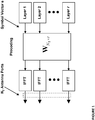
- An illustration of the spatial multiplexing operation is provided in Figure 1 .
- the information carrying symbol vector s is multiplied by an N T x r precoder matrix W N T ⁇ r , which serves to distribute the transmit energy in a subspace of the N T (corresponding to N T antenna ports) dimensional vector space.
- the precoder matrix is typically selected from a codebook of possible precoder matrices, and typically indicated by means of a precoder matrix indicator (PMI), which specifies a unique precoder matrix in the codebook for a given number of symbol streams.
- PMI precoder matrix indicator
- the r symbols in s each correspond to a layer and r is referred to as the transmission rank. In this way, spatial multiplexing is achieved since multiple symbols can be transmitted simultaneously over the same time/frequency resource element (TFRE).
- the number of symbols r is typically adapted to suit the current channel properties.
- the precoder, W N T ⁇ r may be a wideband precoder, which is constant over frequency, or frequency selective. Note that the signals above (e.g., y n ) could alternatively represent a signal in the time-domain. It is generally understood that signals described herein may represent signals in other domains than in the time-frequency grid of an OFDM system.
- the precoder matrix is often chosen to match the characteristics of the N R ⁇ N T MIMO channel matrix H, resulting in so-called channel dependent precoding. This is also commonly referred to as closed-loop precoding and generally strives for focusing the transmit energy into a subspace which is strong in the sense of conveying much of the transmitted energy to the user equipment. In addition, the precoder matrix may also be selected to strive for orthogonalizing the channel, meaning that after proper linear equalization at the user equipment the inter-layer interference is reduced.
- the user equipment transmits, based on channel measurements in the forward link (downlink), recommendations to the eNodeB of a suitable precoder to use.
- the user equipment selects a precoder out of a countable and finite set of precoder alternatives, referred to as a precoder codebook.
- a single precoder that is supposed to cover a large bandwidth (wideband precoding) may be fed back. It may also be beneficial to match the frequency variations of the channel and feedback a frequency-selective precoding report, e.g., several precoders, one per subband.
- CSI channel state information
- other information may comprise channel quality indicators (CQIs) as well as a transmission rank indicator (RI).
- CQIs channel quality indicators
- RI transmission rank indicator
- the use of closed-loop precoding means the eNodeB is selecting precoder(s) and transmission rank and thereafter signals the selected precoder that the user equipment is supposed to use.
- MAC Medium Access Control
- PHY Physical Layer
- a method for controller operation includes indicating that the controller is operating in a cooperative beam switching mode, transmitting a beam formed reference signal (BFRS), from each communications device being served by the controller, receiving a measurement of a communications channel between the controller and the communications device and an indicator indicating a transmission unit corresponding to the measurement of the communications channel, receiving a transmission intended for a communications device, and causing the transmission to be transmitted to the communications device.
- BFRS beam formed reference signal
- the BFRS is beam formed using a plurality of beam patterns, the beam pattern used in beam forming the BFRS changes once per transmission unit, and the transmission is transmitted using measurement of the communications channel and the indicator from the communications device.
- Active antennas may comprise many subelements and arrays of active antennas may comprise even more. Such antenna configurations were neither thought of, nor taken into account, when existing codebooks where designed.
- at least one example object of the example embodiments presented herein is to provide spatial multiplexing transmission techniques in MIMO wireless communications which account for the various subelements which may be comprised in active antenna arrays. Some of the example embodiments are also directed providing improved data communications which may provide beamformers with improved link adaptation, modulation, precoding, and transmission rank of the multiple antenna system.
- the example embodiments presented herein may also be applied without the use of spatial multiplexing, in which case only elevation beamforming may be utilized.
- spatial multiplexing may be utilized where beamforming may be provided in only the azimuth direction. According to other example embodiments, beamforming may be provided in both an azimuth and elevation domain.
- some of the example embodiments may be directed towards a method, in an eNodeB, for generating downlink communications in a multiple antenna system.
- the eNodeB is comprised in a wireless communications network.
- the method comprises transmitting, to a plurality of user equipments, a plurality of Channel State Information (CSI) reference signals.
- CSI Channel State Information
- Each reference signal is beamformed into a distinct direction within at least one correlated domain of the multiple antenna system, wherein the at least one correlated domain is an elevation and/or azimuth domain.
- CSI Channel State Information
- the method further comprises receiving, from a specific user equipment, at least one Channel State Information (CSI) report for at least a subset of reference signals of said plurality of transmitted reference signals wherein the CSI report comprises at least one of a Precoder Matrix Indicator (PMI) a Rank Indicator (RI) and at least one signal quality indicator (CQI).
- the method further comprises determining at least one candidate beamforming direction for the specific user equipment, wherein the at least one candidate beamforming direction is based, at least in part, on a signal quality assessment received from the specific user equipment, which comprises a reference signal received power (RSRP), a reference signal received quality (RSRQ), and a received signal strength indicator (RSSI).
- RSRP reference signal received power
- RSRQ reference signal received quality
- RSSI received signal strength indicator
- the method also comprises determining at least one primary reference signal among said first set of reference signals based on the received at least one CSI report.
- the method further comprises generating downlink communication signals for antenna element(s) and/or sub-elements of the multiple antenna system.
- the downlink communication signals are beamformed into a transmitting direction that aligns most closely with a beamforming direction, consistent with the at least one candidate beamforming direction, of the at least one primary reference signal, as compared to any other beamforming direction of reference signals comprised in the first set of reference signals.
- Some of the example embodiments may be directed towards an eNodeB, for generating downlink communications in a multiple antenna system.
- the eNodeB is comprised in a wireless communications network.
- the eNodeB comprises radio circuitry configured to transmit, to a plurality of user equipments, a plurality of reference signals.
- Each reference signal is beamformed into a distinct direction within at least one correlated domain of the multiple antenna system.
- the radio circuitry is further configured to receive, from a specific user equipment, at least one CSI report for at least a subset of reference signals of said plurality of transmitted CSI reference signals, wherein the CSI report comprises at least one of a Precoder Matrix Indicator (PMI), a Rank Indicator (RI), and at least one signal quality indicator (CQI).
- PMI Precoder Matrix Indicator
- RI Rank Indicator
- CQI signal quality indicator
- the eNodeB further comprises processing circuitry configured to determine at least one candidate beamforming direction for the specific user equipment, wherein the at least one candidate beamforming direction is based, at least in part, on a signal quality assessment received from the specific user equipment, which comprises a reference signal received power (RSRP), a reference signal received quality (RSRQ), and a received signal strength indicator (RSSI).
- the eNodeB further comprises processing circuitry configured to determine at least one primary reference signal among said first set of reference signals.
- the processing circuitry is further configured to generate downlink communication signals for antenna element(s) and/or sub-elements of the multiple antenna system.
- the downlink communication signals are beamformed into a beamforming direction, consistent with the at least one candidate beamforming direction, of the at least one primary reference signal, as compared to any other beamforming direction of reference signals comprised in the first set of reference signals.
- Some of the example embodiments may be directed towards a method in a user equipment, for establishing beamforming for a multiple antenna system.
- the user equipment is comprised in a wireless communications network.
- the method comprises receiving, from an eNodeB, a plurality of Channel State Information (CSI) reference signals. Each reference signal is beamformed into a distinct direction within at least one correlated domain of the multiple antenna system, wherein the at least one correlated domain is an elevation and/or azimuth domain.
- the method further comprises measuring a corresponding effective channel for, at least a subset, of the plurality of reference signals.
- the method also comprises determining a recommended effective channel, among the effective channels, based on a performance metric relating to a performance of a data transmission over a given effective channel.
- the method also comprises transmitting, to a wireless communication network, an index identifying the recommended effective channel.
- the method also comprises transmitting, to a wireless communication network, a Channel State Information (CSI) report for the recommended effective channel, wherein the CSI report comprises at least one of a Precoder Matrix Indicator (PMI), a Rank Indicator (RI), and at least one signal quality indicator (CQI); wherein, the CSI report is used to determine beamforming direction for generating downlink communication signals for antenna elements and/or sub-elements of the multiple antenna system, wherein at least one candidate beamforming direction is determined based, at least in part, on a signal quality assessment received from the user equipment, which comprises a reference signal received power (RSRP), a reference signal received quality (RSRQ), and a received signal strength indicator (RSSI).
- RSRP reference signal received power
- RSRQ reference signal received quality
- RSSI received signal strength indicator
- Some of the example embodiments may be directed towards a user equipment, for establishing beamforming for a multiple antenna system.
- the user equipment is comprised in a wireless communications network.
- the user equipment comprises radio circuitry configured to receive, from an eNodeB, a plurality of Channel State Information (CSI) reference signals. Each reference signal is beamformed into a distinct direction within at least one correlated domain of the multiple antenna system, wherein the at least one correlated domain is an elevation and/or azimuth domain.
- the user equipment also comprises processing circuitry configured to measure a corresponding effective channel for, at least a subset, of the plurality of reference signals.
- CSI Channel State Information
- the processing circuitry further configured to determine a recommended effective channel, among the effective channels, based on a performance metric relating to a performance of a data transmission over a given effective channel.
- the radio circuitry is further configured to transmit, to a wireless communication network, an index identifying the recommended effective channel.
- the radio circuitry is further configured to transmit, to a wireless communication network, a Channel State Information (CSI) report for the recommended effective channel, wherein the CSI report comprises at least one of a Precoder Matrix Indicator (PMI), a Rank Indicator (RI), and at least one signal quality indicator (CQI); wherein, the CSI report is used to determine beamforming direction for generating downlink communication signals for antenna elements and/or sub-elements of the multiple antenna system, wherein at least one candidate beamforming direction is determined based, at least in part, on a signal quality assessment received from the user equipment, which comprises a reference signal received power (RSRP), a reference signal received quality (RSRQ), and a received signal strength indicator (RSSI).
- RSRP reference signal received power
- RSRQ reference signal received quality
- RSSI received signal strength indicator
- An example advantage of some of the example embodiments presented herein is that the CSI feedback from the user equipment may be significantly better aligned with the elevation beamformer used for the data transmission, thereby increasing the performance in terms of spectral efficiency and robustness.
- Some of the example embodiments presented herein are directed towards providing user equipment specific beamforming for downlink communications. As part of the development of the example embodiments presented herein, a problem will first be identified and discussed. The description below is organized as follows.
- Examples of existing precoders will be briefly discussed under the subheading "Examples of Existing Precoder Codebooks for LTE". Thereafter, an introduction on reference symbols which a user equipment may utilize for precoder determination is provided under the subheading "Channel State Information Reference Symbols (CSI-RS)”. Afterwards an introduction of CoMP transmission is provided under the subheading "Coordinated Multipoint Transmission”. CoMP feedback may be used by the user equipment to send signal quality measurements to the eNodeB. The eNodeB may in-turn provide the downlink communications based on, at least in part, these measurements, according to some of the example embodiments. Thereafter, an introduction to antenna arrays and active antennas is provided under the subheadings "Antenna Arrays" and “Active Antennas”, respectively. Afterwards, a detailed analysis of some of the example embodiments will be provided.
- CSI-RS Channel State Information Reference Symbols
- LTE Release-8 the first release of LTE, features the support codebook based precoding for 2 antennas. Up to two layers can be transmitted (rank 1 and rank 2), thus making the precoder matrix W 2 xr of dimension 2x1 and 2x2, respectively.
- LTE Release-10 supports a transmission mode for up to 8-layer spatial multiplexing for 8 Tx antennas using user equipment specific RS. Rank adaptation and possibly channel dependent precoding is also supported.
- User equipment specific RS is used for demodulation purposes and because of that the eNodeB is free to use whatever precoder(s) it wants to, but it may be assisted in the determination of precoder(s) via CSI feedback from the user equipment that includes recommended precoder(s).
- CSI-RS channel state information
- CRS common reference symbols
- the CSI-RS is not used for demodulation of the data signal, and thus does not require the same density (i.e., the overhead of the CSI-RS is substantially less).
- CSI-RS provides a much more flexible means to configure CSI feedback measurements (e.g., which CSI-RS resources to measure on may be configured in a user equipment specific manner).
- the support of antenna configurations larger than 4 antennas should resort to CSI-RS, since the CRS is only defined for at most 4 antennas.
- the user equipment may estimate the channel and consequently also figure out which precoder suits the particular channel. For the purpose of CSI feedback determination, the user equipment assumes that each of the rows corresponds to an antenna port (ports 15-22) on which a CSI-RS port signal is transmitted.
- the first row represents antenna port 15, the second row represents antenna port 16, and so on.
- Each CSI-RS port signal is typically transmitted from an antenna of its own, meaning that there is a direct correspondence between a CSI-RS port and a physical antenna.
- Coordinated Multi Point (CoMP) transmission and reception refers to a system where the transmission and/or reception at multiple, geographically separated antenna sites is coordinated in order to improve system performance.
- the coordination can either be distributed, by means of direct communication between the different sites, or by means of a central coordinating node.
- CoMP is a tool introduced in LTE to improve the coverage of high data rates, the cell-edge throughput and/or to increase system throughput.
- the goal is to distribute the user perceived performance more evenly in the network by taking control of the inter-cell interference.
- a CSI-RS resource may loosely be described as the pattern of resource elements on which a particular CSI-RS configuration is transmitted.
- a CSI-RS resource may be configured through RRC signaling.
- CSI-RSRP CSI-RS received power
- base stations are often equipped with multiple antennas to be used for reception and transmission.
- the antennas intended for a transmission point e.g., a cell, and/or a sector
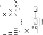
- Some typical antenna array constellations are illustrated in Figure 2 .
- one common antenna array layout is to use co-polarized antennas in order to construct antenna arrays as shown in Figure 2(a) .
- another common layout is to instead use cross-polarized antennas as shown in Figure 2(b) .
- a 2 Tx cross-polarized antenna array (c.f. the top most antenna setup in Figure 2(b) ) implies that the antenna array is fed with two signals, x 1 and x 2 .
- This is illustrated in Figure 3 where it has been assumed that a 2 Tx antenna array is used with codebook based precoding, so that the transmitted signal is x 2 ⁇ 1 W 2 ⁇ r s r ⁇ 1 .
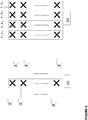
- An active antenna comprises a number of subelements that jointly form the antenna.
- a subelement in practice may be realized by a small physical device, as is illustrated.
- Each subelement will have a polarization direction which potentially can be orthogonal to another subelement's polarization.
- Figure 4(b) where a subelement with orthogonal polarization compared to the subelement in Figure 4(a) is shown.
- Figure 4(c) an active antenna array which consists of N s subelements is shown. In general, but not necessarily, all the subelements of an active antenna are of the same polarization. Note that each given subelement i can be fed the given signal x ( i ) not necessarily equal to x ( i ) .
- the notation x i ( j) when dealing with more than one active antenna, the notation x i ( j) will be utilized when referring to a signal, or function, related to the j :th subelement in the i :th antenna. These indexes will however be omitted when it is clear from the context what is being referred.
- an 8 Tx antenna array may be created.
- the signals x i j are no longer explicitly shown but they are still assumed to be present in the same manner as in Figure 5(a) .
- precoder codebooks in different standards have been designed for conventional antenna arrays. For example, in LTE Release 10 and beyond, precoder codebooks for 2, 4 or 8 Tx antennas are supported. There is thus a precoder codebook suitable for each antenna array type. Hence, when using, for example, a 2 Tx antenna array, the standard is designed to use the 2 Tx codebook meaning that x 1 and x 2 can be fed to the antenna array just as in Figure 3 .
- Active antennas comprise many subelements and arrays of active antennas comprise even more. Such antenna setups were neither thought of, nor taken into account, when the existing codebooks were designed. Therefore, existing codebooks do not utilize the fact that the subelements can be accessed as illustrated in Figure 5 .
- the sheer number of sub-element antenna ports can create so many degrees of freedom that the CSI feedback overhead from a user equipment becomes prohibitive.
- Active antennas, antenna arrays and arrays of active antennas may be generalized to a system of multiple antennas.
- the phrase multiple antenna system is used to describe a set of antennas (comprising one active antenna with multiple sub-elements) that constitutes a transmission point (i.e., with the intent to serve a sufficiently isolated region of space, such as a cell and/or sector).
- the techniques described herein allow for feedback from the user equipment to be generated and used for guiding user equipment specific beamforming in the azimuth and/or elevation domain by using multiple antenna systems even when existing codebooks not are designed for this purpose.
- FIG. 6 provides an example illustration of a general overview of the example embodiments.
- the communications which may be transmitted between an eNodeB and a user equipment are illustrated.
- each of the reference signals b n may be transmitted in a distinct beamforming direction, however, the transmitted data itself may be overlapping.
- the eNodeB may first transmit a plurality of CSI-RS, with each CSI-RS being beamformed in a direction within the correlated domain (circle 1).
- the eNodeB may thereafter determine at least one direction (or beam) within the correlated domain which is likely for a subsequent data transmission to the user equipment (circle 2).
- the eNodeB may also configure the user equipment to measure CSI (e.g., PMI/RI/CQI) for at least one CSI-RS resource that is beamformed in a direction that is well aligned, or most closely aligned, with the determined direction for the subsequent data (circle 3).
- CSI e.g., PMI/RI/CQI
- the eNodeB may receive CSI (e.g., PMI/RI/CQI) from the user equipment for the transmitted CSI-RS (circle 4). Then, the eNodeB may transmit data to the user equipment by taking the CSI feedback into account.
- CSI e.g., PMI/RI/CQI
- the example embodiments may be utilized to transmit a plurality of CSI-RS resources, precoded in such a way that each CSI-RS may span a direction within a correlated domain, for example, a correlated vector space, of a multiple antenna system.
- CSI e.g., PMI/RI/CQI
- the eNodeB may ensure that the CSI feedback report is accurate for the transmission (e.g., that the eNodeB can follow the recommended PMI/RI/CQI with only modest changes, to for example the transport format). This will significantly improve the link adaptation.
- the link adaptation may comprise the selection of the transport block size (e.g., code rate), modulation, precoding, and the transmission rank of the multiple antenna system.
- a particularly useful example application of the embodiments presented herein is for the purpose of elevation beamforming, since the elevation direction typically forms a highly correlated domain of an active antenna configuration.
- multiple CSI-RS resources are transmitted, with each resource being associated and precoded with a corresponding elevation beam.
- the eNodeB can thus configure a user equipment to measure and report CSI (e.g., PMI/RI/CQI) for at least one CSI-RS resource that is closely aligned with an expected elevation beam of a subsequent downlink data transmission.
- CSI e.g., PMI/RI/CQI
- the elevation direction where most transmitted power is received by a user equipment.
- the reported CSI is directly applicable in use for the corresponding data transmission that applies the elevation beamformer.
- a set of CSI-RS signals are configured to span different elevation directions.
- a corresponding user equipment may be configured to measure and report CSI (e.g., PMI/RI/CQI) for a CSI-RS that is associated with an elevation beam that is most closely aligned with the candidate elevation beamformer.
- CSI e.g., PMI/RI/CQI
- N A Tx active antenna array where each antenna comprises N S subelements.
- x ⁇ N A N S ⁇ 1 u B N A N S ⁇ N A u x N A ⁇ 1 u
- x N A ⁇ 1 ( u ) is a CSI-RS signal for N A ports.
- the first N S values correspond to the subelements of one active antenna and that the second N S values correspond to the subelements of a second active antenna, etc.
- the equation above describes a mapping from the N A ports CSI-RS to the N A N S subelements.
- each index u corresponds to transmission in a certain direction defined by the beamformers b 1 ,..., b Nu .
- the different CSI-RS signals, x N A ⁇ 1 (u) would be configured as to be orthogonal; for example, separated to different time/frequency resources.
- the CSI-RS signals may be configured in any other orientation known in the art.
- some of the user equipments may be configured to measure and report back CSI (e.g., PMI/RI/CQI) for at least one CSI-RS resource that is precoded using an elevation beam that is closely, or most closely, aligned with an expected elevation beam of a subsequent downlink data transmission.
- CSI e.g., PMI/RI/CQI
- a residual difference between the directional beamformer (e.g., elevation beamformer) used for the data transmission as compared to that used for the configured CSI-RS resource(s), can be compensated by the eNodeB by, for example, an ACK/NACK based outer loop link adaptation in the network.
- the directional beamformer e.g., elevation beamformer
- subelement may refer to any virtualization (e.g., linear mapping) of the physical antenna subelements.
- pairs of physical subelements may be fed by the same signal, and hence share the same virtualized subelement antenna port.
- beamforming direction and “beamformer” may be used interchangeably. Such terms should be considered non-limiting and a beamforming direction should be interpreted in the general sense of a complete beamformer vector/matrix, which may have a direction span and a phase. It should be appreciated that according to some of the example embodiments, the structure herein corresponds to each active antenna in the array having the same elevation beam. It is however possible to use a different elevation beam on each active antenna.
- the eNodeB may receive the sufficient CSI information for downlink precoding between the two polarizations, whereas the uplink control overhead and the measurement complexity at the user equipment is reduced, since the measurement and reporting is based on a small two port CSI-RS, contrary to state of the art which corresponds to measurement/reporting on a CSI-RS with the same number of ports as the total number of antennas in the array.
- example embodiments presented herein may be utilized to jointly cover the azimuth and elevation domain.
- a set of CSI-RS signals (with a reduced number of ports), each precoded to point in a certain elevation and azimuth direction.
- the eNodeB can receive the sufficient CSI information for downlink precoding with a minimum of uplink control overhead and user equipment complexity.
- a user equipment in support of CoMP a user equipment may be configured to measure and report CSI (e.g., PMI/RI/CQI) based on multiple CSI-RS resources, corresponding to the CSI-RS resources in a CoMP Measurement Set. More specifically, the UE can be configured with a plurality of CSI Processes for channel state information feedback. Each such CSI process can be configured to represent the channel state of a particular CSI-RS resource of choice, and enables periodic and aperiodic CSI feedback for said CSI-RS resource.
- CSI e.g., PMI/RI/CQI
- a plurality of CSI processes is used to configure a user equipment to measure and report CSI for a plurality of CSI-RS resources that each has been precoded in a certain direction.
- a user equipment may be configured to feedback CSI for all configured CSI-RS (i.e., for all directions), and thus maximize the flexibility for an eNodeB in selecting a downlink precoder.
- the user equipment may be configured to measure and report only for a subset of the CSI-RS resources (e.g., corresponding to directions that are most relevant for subsequent downlink data transmission).
- uplink and downlink channels there is a strong coupling between uplink and downlink channels (provided by electromagnetic reciprocity). For example, if signals originate from a certain direction in the uplink, the same direction is with high probability also suitable for downlink transmissions.
- the configuration of which precoded CSI-RS resource(s) a user equipment shall report CSI for is aided by uplink measurements.
- a user equipment may be configured to report CSI based on measurements on the CSI-RS that is precoded in the direction that most closely aligns with the strongest uplink received direction (or more specifically, the eNodeB determines that the most likely direction of a subsequent data transmission will be well aligned with the uplink measurement, and thus configures the user equipment to report CSI for a corresponding CSI-RS resources).
- the user equipment may assist the network in selecting which CSI-RS to use for CSI reporting.
- a user equipment When a user equipment performs channel measurements based on a specific CSI-RS resource it will effectively measure the combined effect of the beamforming (applied to the CSI-RS resource) and the effects of the radio propagation channel.
- each CSI-RS resource is associated with an effective channel including both the beamforming effect and the radio propagation environment.
- the user equipment may thus recommend an effective channel to the network (to use for a subsequent data transmission) based on, for example, selecting effective channel with the highest assessed performance. For example, an index identifying a recommended CSI-RS, among the plurality of CSI-RS resources, may be signaled to the network. Note that there is a one-to-one correspondence between an effective channel and a CSI-RS resource.
- the user equipment may report CSI only for the recommended CSI-RS resource, thereby reducing overhead, while providing sufficient information to the network to perform accurate link adaptation, beamforming (in e.g., elevation domain) and precoding (in e.g., azimuth domain).
- beamforming in e.g., elevation domain
- precoding in e.g., azimuth domain
- the mechanism of CSI-RSRP is used to aid the eNodeB in configuring a user equipment to report CSI for the appropriate CSI-RS resource(s). That is, CSI-RSRP measurement reports are used by the eNodeB to determine likely directions for subsequent downlink data transmissions, and thus which CSI-RS resource to configure a user equipment to perform CSI measurements/reporting on.
- a user equipment is configured to measure and report CSI-RSRP for at least a subset of the transmitted CSI-RS that are precoded in e.g., elevation domain.
- a different set of CSI-RS resources may be transmitted for the purpose of RSRP feedback.
- This set of RSRP CSI-RS resources could, however, be partially overlapping with the traditional CSI-RS resources (e.g., the CSI-RS resources discussed for the preceding embodiments that are used for CSI feedback).
- the eNodeB may derive information about which direction is suitable for downlink data transmission, for example, by applying the above mentioned technique (e.g., choosing the directional beamformer used for the CSI-RS with the highest reported signal quality).
- the eNodeB may next configure the user equipment to report CSI using the traditional CSI-RS that, for example, is associated with the direction that is most aligned with the determined direction for subsequent data transmissions.
- RSRP CSI-RS each typically using a small set of ports and thus having lower overhead
- a larger set of directions can be excited thereby achieving a higher resolution for the determined direction for data transmissions, thereby increasing the received signal power and reducing interference to other user equipments.
- FIG 7 illustrates an example of an eNodeB 401 which may incorporate some of the example embodiments discussed above.
- the eNodeB 401 may comprise a radio circuitry 410 configured to receive and transmit any form of communications or control signals within a network.
- the radio circuitry 410 may be comprised as any number of transceiving, receiving, and/or transmitting units or circuitry. It should further be appreciated that the radio circuitry 410 may be in the form of any input/output communications port known in the art.
- the radio circuitry 410 may comprise RF circuitry and baseband processing circuitry (not shown).
- the eNodeB 401 may further comprise at least one memory unit or circuitry 430 that may be in communication with the radio circuitry 410.
- the memory 430 may be configured to store received or transmitted data and/or executable program instructions.
- the memory 430 may also be configured to store any form of beamforming information, reference signals, and/or feedback data or information.
- the memory 430 may be any suitable type of computer readable memory and may be of volatile and/or non-volatile type.
- the eNodeB 401 may further comprise further comprises a network interface 440 and processing circuitry 420 which may be configured to generate and analyze reference signals, and generate beamformed communications.
- the processing circuitry 420 may also be configured to provide configuration instructions to the user equipment.
- the processing circuitry 420 may be any suitable type of computation unit, e.g. a microprocessor, digital signal processor (DSP), field programmable gate array (FPGA), or application specific integrated circuit (ASIC) or any other form of circuitry. It should be appreciated that the processing circuitry need not be provided as a single unit but may be provided as any number of units or circuitry.
- FIG 8 illustrates an example of a user equipment which may incorporate some of the example embodiments discussed above.
- the user equipment 505 may comprise a radio circuitry 510 configured to receive and transmit any form of communications or control signals within a network.
- the radio circuitry 510 may be comprised as any number of transceiving, receiving, and/or transmitting units or circuitry. It should further be appreciated that the radio circuitry 510 may be in the form of any input/output communications port known in the art.
- the radio circuitry 510 may comprise RF circuitry and baseband processing circuitry (not shown).
- the user equipment 505 may further comprise at least one memory unit or circuitry 530 that may be in communication with the radio circuitry 510.
- the memory 530 may be configured to store received or transmitted data and/or executable program instructions.
- the memory 530 may also be configured to store any form of beamforming information, reference signals, and/or feedback data or information.
- the memory 530 may be any suitable type of computer readable memory and may be of volatile and/or non-volatile type.
- the user equipment 505 may further comprise further processing circuitry 520 which may be configured to perform measurements are set configurations provided by the eNodeB.
- the processing circuitry 520 may be any suitable type of computation unit, e.g. a microprocessor, digital signal processor (DSP), field programmable gate array (FPGA), or application specific integrated circuit (ASIC) or any other form of circuitry. It should be appreciated that the processing circuitry need not be provided as a single unit but may be provided as any number of units or circuitry.
- Figures 9 through 11 are flow diagrams depicting example operations which may be taken by the eNodeB of Figure 8 , during the generation of downlink communications in a multiple antenna system, according to some of the example embodiments.
- Figures 9-11 comprises some operations which are illustrated with a darker border and some operations which are illustrated with a lighter border.
- the operations which are comprised in a darker border are operations which are comprised in the broadest example embodiment.
- the operations which are comprised in a lighter border are example embodiments which may be comprised in, or a part of, or are further operations which may be taken in addition to the operations of the border example embodiments. It should be appreciated that these operations need not be performed in order. Furthermore, it should be appreciated that not all of the operations need to be performed.
- the example operations may be performed in any order and in any combination.
- Figure 9 illustrates example eNodeB operations which are described under at least the subheadings "Generating CSI Feedback for Elevation Beamforming using Multiple CSI-RS”, “Generating Azimuth Beamforming Feedback from Multiple CSI-RS”, “Generating Joint Azimuth and Elevation Beamforming Feedback from Multiple CSI-RS”, “Selection of CSI-RS for CSI Reporting based on Uplink Measurements” and “Selection of CSI-RS for CSI Reporting based on CSI-RSRP Reports”.
- Figure 9 describes a non-limiting example embodiment in which an eNodeB may first determine an approximate (or candidate) beamforming direction and request or configure the user equipment to provide measurements or a CSI report based on the approximation.
- a beamforming direction for downlink communications may be provided based on a primary reference signal determined via the CSI report.
- the amount of user equipment reporting/signaling may be reduced.
- the eNodeB is configured to transmit 10, to a plurality of user equipments, a plurality of reference signals. Each reference signal is beamformed into a distinct direction within at least one correlated domain of the multiple antenna system.
- the radio circuitry 410 is configured to transmit, to the plurality of user equipments, the plurality of reference signals.
- the at least one correlated domain may be an elevation and/or an azimuth domain.
- the plurality of reference signals may be CSI-RS.
- the eNodeB may determine 26 at least one candidate beamforming direction, within the at least one correlated domain of the multiple antenna system, for a subsequent data transmission.
- the processing circuitry 420 may be configured to determine the at least one candidate beamforming direction, within the at least one correlated domain of the multiple antenna system, for a subsequent data transmission.
- the determining 26 may be provided by transmitting a second set of beamformed reference signals, which may be a subset of, or equal to, the reference signals described in operation 10.
- the second set of reference signals may be sent prior, after or at the same time as the reference signals referred to in operation 10.
- the eNodeB may configure the specific user equipment to report signal quality assessments for the second set of reference signals.
- the reported signal quality assessments of the second set of beamformed reference signals may be utilized to assist in the determination of the candidate beamforming direction.
- the determining 26 may be provided by transmitting a second set of reference signals beamformed into a distinct direction within at least one correlated domain of the multiple antenna system, which may be a subset of, or equal to, the reference signals described in operation 10.
- the second set of beamformed reference signals may be sent prior, after or at the same time as the reference signals referred to in operation 10.
- the eNodeB may configure the specific user equipment, or there may be a predetermined contract, to report signal quality assessments for the second set of beamformed reference signals. Therefore, the determination of the at least one candidate beamforming direction may be based, at least in part, on a plurality of signal quality assessments received from the specific user equipment.
- the determined at least one candidate beamforming direction may correspond with a higher signal quality assessments which is favored over directions associated with lower signal quality assessments.
- the signal quality assessments may be a RSRP, RSRQ and/or a RSSI.
- the determination of the at least one candidate beamforming direction may be based, at least in part, on uplink measurements on signals transmitted by the user equipment.
- the eNodeB may be configured to estimate the power in a particular direction by applying a beamformer on the received signal.
- the eNodeB may perform measurements of the various signals to determine signal energy or power levels received from signals in various directions.
- the at least one candidate beamforming direction may be associated with a higher received power that is favored or preferred over a direction associated with a lower received power.
- the eNodeB may configure the user equipment to report CSI with respect to the reference signals (of operation 10) which are beamformed in a similar manner as the candidate beamforming direction.
- the eNodeB is further configured to receive 30, from the specific user equipment, at least one CSI report for the plurality of transmitted reference signals.
- the radio circuitry 410 is configured to receive, from the specific user equipment, the at least one CSI report for the plurality of transmitted reference signals.
- the CSI report may comprise a PMI, RI and/or at least one CQI.
- the eNodeB is configured to receive 34 a CSI report from the specific user equipment for a single reference signal.
- the radio circuitry 410 is configured to receive the CSI report.
- the single reference signal may be associated with a signal with a beamforming direction that aligns most closely with the at least one candidate beamforming direction, as compared to any other beamforming direction of any other reference signals of the plurality of reference signals (transmitted in operation 10).
- the eNodeB is further configured to determine 38 at least one primary reference signal among the first set of reference signals.
- the processing circuitry 420 is configured to determine the at least one primary reference signal among the first set of reference signals.
- the determined primary reference signal is the single reference signal described in example operation 34.
- the eNodeB is further configured to generate 50 downlink communications signals for antenna element(s) and/or subelements of the multiple antenna system.
- the downlink communication signals are beamformed into a transmitting direction that aligns most closely with a beamforming direction of the at least one primary reference signal, as compared to any other beamforming direction of the reference signals comprised in the first set of reference signals.
- the processing circuitry 420 is configured to generate the downlink communication signals for antenna element(s) and/or subelements of the multiple antenna system.
- Figure 10 illustrates example eNodeB operations which are described under at least the subheadings "Generating CSI Feedback for Elevation Beamforming using Multiple CSI-RS”, “Generating Azimuth Beamforming Feedback from Multiple CSI-RS”, “Generating Joint Azimuth and Elevation Beamforming Feedback from Multiple CSI-RS” and “Configuration of CSI Feedback using CoMP Measurement Set”.
- Figure 10 describes a non-limiting example embodiment in which an eNodeB may configure the user equipment to send measurements or CSI reports on a plurality of reference signals via a CoMP measurement set.
- an eNodeB may configure the user equipment to send measurements or CSI reports on a plurality of reference signals via a CoMP measurement set.
- multiple candidate beamforming directions may be determined and each determined candidate beamforming direction may be comprised in the CoMP measurement set.
- a candidate beamforming direction need not be determined and a beamforming direction for downlink data may be determined via the plurality of CSI reports provided by the user equipment. By providing a large set of reported data, the beamforming direction may be accurately determined.
- the eNodeB is configured to transmit 10, to a plurality of user equipments, a plurality of reference signals. Each reference signal is beamformed into a distinct direction within at least one correlated domain of the multiple antenna system.
- the radio circuitry 410 is configured to transmit, to the plurality of user equipments, the plurality of reference signals.
- the at least one correlated domain may be an elevation and/or an azimuth domain.
- the plurality of reference signals may be CSI-RS.
- the eNodeB may determine 26 at least one candidate beamforming direction, within the at least one correlated domain of the multiple antenna system, for a subsequent data transmission.
- the processing circuitry 420 may be configured to determine the at least one candidate beamforming direction, within the at least one correlated domain of the multiple antenna system, for a subsequent data transmission.
- the at least one candidate beamforming direction is a plurality (e.g., more than one) candidate beamforming direction.
- the determining 26 may be provided by transmitting a second set of reference signals beamformed into a distinct direction within at least one correlated domain of the multiple antenna system, which may be a subset of, or equal to, the reference signals described in operation 10.
- the second set of beamformed reference signals may be sent prior, after or at the same time as the reference signals referred to in operation 10.
- the eNodeB may configure the specific user equipment, or there may be a predetermined contract, to report signal quality assessments for the second set of beamformed reference signals. Therefore, the determination of the candidate beamforming directions may be based, at least in part, on a plurality of signal quality assessments received from the specific user equipment.
- the determined candidate beamforming directions may correspond with a higher signal quality assessments which are favored over directions associated with lower signal quality assessments.
- the signal quality assessments may be a RSRP, RSRQ and/or a RSSI.
- the determination of the candidate beamforming directions may be based, at least in part, on uplink measurements received from signals transmitted by the user equipment.
- the eNodeB may be configured to estimate the power in a particular direction by applying a beamformer on the received signal.
- the eNodeB may perform measurements of the various signals to determine signal energy or power levels of the received from signals in various directions.
- the candidate beamforming directions may be associated with higher received powers that are favored or preferred over directions associated with lower received powers.
- the eNodeB may configure the user equipment to report CSI with respect to the reference signals (of operation 10) which are beamformed in a similar manner as the candidate beamforming directions, such configuration is explained in example operation 29.
- the eNodeB may configure 29 a plurality of CSI processes and/or a CoMP Measurement Set for a specific user equipment.
- the CSI processes and/or the CoMP Measurement Set may comprise at least the plurality of reference signals associated with a plurality of CSI reports.
- the processing circuitry 420 may configure the CoMP Measurement Set for the specific user equipment.
- the CSI processes and/or the CoMP Measurement set may comprise reference signals associated with the determined candidate beamforming directions, as explained in example operation 26.
- the eNodeB is further configured to receive 30, from the specific user equipment, at least one CSI report for a first set of reference signals of the plurality of transmitted reference signals.
- the radio circuitry 410 is configured to receive, from the specific user equipment, the at least one CSI report for the first set of reference signals of the plurality of transmitted reference signals.
- the CSI report may comprise a PMI, RI and/or at least one CQI.
- the receiving 30 may comprise receiving 33 a plurality of CSI reports.
- the radio circuitry 410 may be configured to receive the plurality of CSI reports.
- the plurality of CSI reports may correspond to reference signals associated with the CSI processes and/or CoMP Measurement Set as described in example operation 29.
- the eNodeB is further configured to determine 38 at least one primary reference signal among the plurality of reference signals.
- the processing circuitry 420 is configured to determine the at least one primary reference signal among the plurality reference signals.
- the determining 38 may be based, at least in part, on the plurality of CSI reports. According to some of the example embodiments, the determining 38 may be further based on CQI of the CSI reports. According to some of the example embodiments, the at least one primary reference signal is a reference signal associated with a CSI report with a highest signal quality indicator or a corresponding highest recommended total transmission rate.
- the eNodeB is further configured to generate 50 downlink communications signals for antenna element(s) and/or subelements of the multiple antenna system.
- the downlink communication signals are beamformed into a transmitting direction that aligns most closely with a beamforming direction of the at least one primary reference signal, as compared to any other beamforming direction of the reference signals comprised in the first set of reference signals.
- the processing circuitry 420 is configured to generate the downlink communication signals for antenna element(s) and/or subelements of the multiple antenna system.
- Figure 11 illustrates example eNodeB operations which are described under at least the subheadings "Generating CSI Feedback for Elevation Beamforming using Multiple CSI-RS”, “Generating Azimuth Beamforming Feedback from Multiple CSI-RS”, “Generating Joint Azimuth and Elevation Beamforming Feedback from Multiple CSI-RS”, “User Equipment Assisted Selection of CSI-RS for CSI Reporting” and “Selection of CSI-RS for CSI Reporting based on CSI-RSRP Reports”.
- Figure 11 describes a non-limiting example embodiment in which an eNodeB may configure the user equipment to send measurements or a CSI report where the user equipment recommends an effective channel.
- the eNodeB is configured to transmit 10, to a plurality of user equipments, a plurality of reference signals. Each reference signal is beamformed into a distinct direction within at least one correlated domain of the multiple antenna system.
- the radio circuitry 410 is configured to transmit, to the plurality of user equipments, the plurality of reference signals.
- the at least one correlated domain may be an elevation and/or an azimuth domain.
- the plurality of reference signals may be CSI-RS.
- the eNodeB may configure 11 a specific user equipment to measure the plurality of reference signals and report an index identifying a recommended effective channel among the plurality of effective channels excited by the plurality of reference signals.
- the processing circuitry 420 may configure the specific user equipment to measure the plurality of reference signals and report the index identifying the recommended effective channel among the plurality of effective channels excited by the plurality of reference signals.
- the eNodeB is further configured to receive 30, from the specific user equipment, at least one CSI report for a first set of reference signals of the plurality of transmitted reference signals.
- the radio circuitry 410 is configured to receive, from the specific user equipment, the at least one CSI report for the first set of reference signals of the plurality of transmitted reference signals.
- the CSI report may comprise a PMI, RI and/or at least one CQI.
- the receiving 30 may further comprise receiving the index from the specific user equipment.
- the radio circuitry 410 may be configured to receive the index from the specific user equipment.
- the index and the at least one CSI report may be received in a same report from the specific user equipment.
- the at least one CSI report may represent the identified recommended effective channel.
- the eNodeB is further configured to determine 38 at least one primary reference signal among the plurality of reference signals.
- the processing circuitry 420 is configured to determine the at least one primary reference signal among the plurality of reference signals.
- the determining 38 may further comprise determining 41 the at least one primary reference signal based on the received index.
- the processing circuitry 420 may be configured to determine the at least one primary reference signal based on the received index.
- the eNodeB is further configured to generate 50 downlink communications signals for antenna element(s) and/or subelements of the multiple antenna system.
- the downlink communication signals are beamformed into a transmitting direction that aligns most closely with a beamforming direction of the at least one primary reference signal, as compared to any other beamforming direction of the reference signals comprised in the first set of reference signals.
- the processing circuitry 420 is configured to generate the downlink communication signals for antenna element(s) and/or subelements of the multiple antenna system.
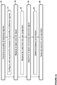
- Figure 12 illustrates example user equipment operations of the user equipment illustrated in Figure 8 for the establishing of beamforming in a multiple antenna system.
- the example operations of Figure 12 are described under at least the subheadings "Generating CSI Feedback for Elevation Beamforming using Multiple CSI-RS”, “Generating Azimuth Beamforming Feedback from Multiple CSI-RS”, “Generating Joint Azimuth and Elevation Beamforming Feedback from Multiple CSI-RS”, “User Equipment Assisted Selection of CSI-RS for CSI Reporting” and “Selection of CSI-RS for CSI Reporting based on CSI-RSRP Reports”.
- Figure 12 comprises some operations which are illustrated with a darker border and some operations which are illustrated with a lighter border.
- the operations which are comprised in a darker border are operations which are comprised in the broadest example embodiment.
- the operations which are comprised in a lighter border are example embodiments which may be comprised in, or a part of, or are further operations which may be taken in addition to the operations of the border example embodiments. It should be appreciated that these operations need not be performed in order. Furthermore, it should be appreciated that not all of the operations need to be performed.
- the example operations may be performed in any order and in any combination.
- the user equipment is configured to receive 60, from an eNodeB, a plurality of reference signals. Each reference signal is beamformed into a distinct direction within at least one correlated domain of the multiple antenna system.
- the radio circuitry 510 is configured to receive, from the eNodeB, the plurality of reference signals. According to some of the example embodiments, the plurality of reference signals is CSI-RS.
- the user equipment is further configured to measure 62 a corresponding effective channel for, at least a subset, of the plurality of reference signals.
- the processing circuitry 520 is configured to measure a corresponding effective channel for, at least a subset of the plurality of reference signals.
- the user equipment is further configured to determine 64 a recommended effective channel, among the effective channels, based on a performance metric relating to a performance of a data transmission over a given effective channel.
- the processing circuitry 520 is configured to determine the recommended effective channel, among the effective channels, based on the performance metric relating to the performance of the data transmission over the given effective channel.
- the performance metric may be an effective received signal power. According to some of the example embodiments, the performance metric is an effective data throughput.
- the user equipment is further configured to transmit 66, to a wireless communications network, an index identifying the recommended effective channel.
- the radio circuitry 510 is configured to transmit, to the wireless communications network, the index identifying the recommended communications network.
- user equipment may further transmit 68 a CSI report for the recommended effective channel.
- the radio circuitry 510 may be configured to transmit the CSI report for the recommended effective channel.
- the CSI report comprises PMI, RI and/or at least one CQI.
- Such configuration instructions may provide information on how to measure and report data comprised in the CSI report, as described herein.
- eNodeB and user equipment should be considered as non-limiting and does in particular not imply a certain hierarchical relation between the two.
- eNodeB could be considered as device 1 and “user equipment” as device 2, and these two devices communicate with each other over some radio channel.
- the example embodiments focus on wireless transmissions in the downlink, it should be appreciated that the example embodiments are equally applicable in the uplink.
- a “device” as the term may be used herein, is to be broadly interpreted to include a radiotelephone having ability for Internet/intranet access, web browser, organizer, calendar, a camera (e.g., video and/or still image camera), a sound recorder (e.g., a microphone), and/or global positioning system (GPS) receiver; a personal communications system (PCS) user equipment that may combine a cellular radiotelephone with data processing; a personal digital assistant (PDA) that can include a radiotelephone or wireless communication system; a laptop; a camera (e.g., video and/or still image camera) having communication ability; and any other computation or communication device capable of transceiving, such as a personal computer, a home entertainment system, a television, etc.
- a device may be interpreted as any number of antennas or antenna elements.
- user equipment is a non-limiting term which means any wireless device, terminal, or node capable of receiving in DL and transmitting in UL (e.g. PDA, laptop, mobile, sensor, fixed relay, mobile relay or even a radio base station, e.g. femto base station).
- UL e.g. PDA, laptop, mobile, sensor, fixed relay, mobile relay or even a radio base station, e.g. femto base station.
- a cell is associated with a radio node, where a radio node or radio network node or eNodeB used interchangeably in the example embodiment description, comprises in a general sense any node transmitting radio signals used for measurements, e.g., eNodeB, macro/micro/pico base station, home eNodeB, relay, beacon device, or repeater.
- a radio node herein may comprise a radio node operating in one or more frequencies or frequency bands. It may be a radio node capable of CA. It may also be a single- or muti-RAT node.
- a multi-RAT node may comprise a node with co-located RATs or supporting multi-standard radio (MSR) or a mixed radio node.
- a computer-readable medium may include removable and non-removable storage devices including, but not limited to, Read Only Memory (ROM), Random Access Memory (RAM), compact discs (CDs), digital versatile discs (DVD), etc.
- program modules may include routines, programs, objects, components, data structures, etc. that perform particular tasks or implement particular abstract data types.
- Computer-executable instructions, associated data structures, and program modules represent examples of program code for executing steps of the methods disclosed herein. The particular sequence of such executable instructions or associated data structures represents examples of corresponding acts for implementing the functions described in such steps or processes.
Claims (12)
- Verfahren in einem eNodeB zum Erzeugen von Abwärtsverbindung-Kommunikationen in einem Mehrantennensystem, wobei der eNodeB in einem drahtlosen Kommunikationsnetzwerk enthalten ist, das Verfahren umfassend:Übertragen (10), an eine Vielzahl von Benutzerausrüstungen, einer Vielzahl von Kanalzustandsinformation-Referenzsignalen, CSI-Referenzsignalen, wobei jedes Referenzsignal in eine bestimmte Richtung innerhalb mindestens einer korrelierten Domäne des Mehrantennensystems strahlengebündelt wird, wobei die mindestens eine korrelierte Domäne eine Elevations- und/oder Azimutdomäne ist;Empfangen (30), von einer spezifischen Benutzerausrüstung, mindestens eines Kanalzustandsinformation-Berichts, CSI-Berichts, für mindestens eine Teilmenge der Vielzahl von CSI-Referenzsignalen, wobei der CSI-Bericht mindestens eines einer Vorcodierermatrixangabe, PMI, einer Rangangabe, RI, und mindestens einer Signalqualitätsangabe, CQI, umfasst;Bestimmen mindestens einer Kandidaten-Strahlenbündelungsrichtung für die spezifische Benutzerausrüstung, wobei die mindestens eine Kandidaten-Strahlenbündelungsrichtung mindestens teilweise auf einer von der spezifischen Benutzerausrüstung empfangenen Signalqualitätsbewertung basiert, die eine Referenzsignal-Empfangsleistung, RSRP, eine Referenzsignal-Empfangsqualität, RSRQ, und eine Empfangssignalstärkeangabe, RSSI, umfasst;Bestimmen (38) mindestens eines primären Referenzsignals unter der Vielzahl von CSI-Referenzsignalen basierend auf dem empfangenen mindestens einen CSI-Bericht; undErzeugen (50) von Abwärtsverbindung-Kommunikationssignalen für Antennenelemente und/oder Unterelemente des Mehrantennensystems, wobei die Abwärtsverbindung-Kommunikationssignale in eine Übertragungsrichtung strahlengebündelt werden, die am nächsten mit einer Strahlenbündelungsrichtung übereinstimmend mit der mindestens einen Kandidaten-Strahlenbündelungsrichtung des mindestens einen primären Referenzsignals im Vergleich mit jeder anderen Strahlenbündelungsrichtung von Referenzsignalen, die in der Teilmenge der Vielzahl von CSI-Referenzsignalen enthalten sind, ausgerichtet ist.
- Verfahren nach Anspruch 1, wobei die Vielzahl von Kanalzustandsinformation-Referenzsignalen, CSI-Referenzsignalen, Kanalzustandsinformation-Referenzsymbole, CSI-RS, umfasst.
- Verfahren nach Anspruch 1, wobei das Verfahren die mindestens eine Kandidaten-Strahlenbündelungsrichtung für die spezifische Benutzerausrüstung in der mindestens einen korrelierten Domäne des Mehrantennensystems für eine anschließende Datenübertragung bestimmt.
- Verfahren nach Anspruch 1, wobei das Empfangen (30) ferner das Empfangen (33) einer Vielzahl von CSI-Berichten für jeweilige Referenzsignale der Vielzahl von Referenzsignalen umfasst.
- eNodeB zum Erzeugen von Abwärtsverbindung-Kommunikationen in einem Mehrantennensystem, wobei der eNodeB in einem drahtlosen Kommunikationsnetzwerk enthalten ist, der eNodeB umfassend:Funkschaltungen (410), konfiguriert zum Übertragen, an eine Vielzahl von Benutzerausrüstungen, einer Vielzahl von Kanalzustandsinformation-Referenzsignalen, CSI-Referenzsignalen, wobei jedes Referenzsignal in eine bestimmte Richtung innerhalb mindestens einer korrelierten Domäne des Mehrantennensystems strahlengebündelt wird, wobei die mindestens eine korrelierte Domäne eine Elevations- und/oder Azimutdomäne ist;
wobei die Funkschaltungen (410) ferner konfiguriert sind zum Empfangen, von einer spezifischen Benutzerausrüstung, mindestens eines Kanalzustandsinformation-Berichts, CSI-Berichts, für eine erste Menge von Referenzsignalen der Vielzahl von übertragenen CSI-Referenzsignalen, wobei der CSI-Bericht mindestens eines einer Vorcodierermatrixangabe, PMI, einer Rangangabe, RI, und mindestens einer Signalqualitätsangabe, CQI, umfasst;Verarbeitungsschaltungen (420), konfiguriert zum Bestimmen mindestens einer Kandidaten-Strahlenbündelungsrichtung für die spezifische Benutzerausrüstung, wobei die mindestens eine Kandidaten-Strahlenbündelungsrichtung mindestens teilweise auf einer von der spezifischen Benutzerausrüstung empfangenen Signalqualitätsbewertung basiert, die eine Referenzsignal-Empfangsleistung, RSRP, eine Referenzsignal-Empfangsqualität, RSRQ, und eine Empfangssignalstärkeangabe, RSSI, umfasst;Verarbeitungsschaltungen (420), konfiguriert zum Bestimmen mindestens eines primären Referenzsignals aus der ersten Menge von Referenzsignalen; undwobei die Verarbeitungsschaltungen (420) ferner konfiguriert sind zum Erzeugen von Abwärtsverbindung-Kommunikationssignalen für Antennenelemente und/oder Unterelemente des Mehrantennensystems, wobei die Abwärtsverbindung-Kommunikationssignale in eine Strahlenbündelungsrichtung strahlengebündelt werden, übereinstimmend mit der mindestens einen Kandidaten-Strahlenbündelungsrichtung des mindestens einen primären Referenzsignals im Vergleich mit jeder anderen Strahlenbündelungsrichtung von Referenzsignalen, die in der ersten Menge von Referenzsignalen enthalten sind. - eNodeB nach Anspruch 5, wobei die Vielzahl von Kanalzustandsinformation-Referenzsignalen Kanalzustandsinformation-Referenzsymbole, CSI-RS, umfasst.
- eNodeB nach Anspruch 5, wobei die Verarbeitungsschaltungen (420) die mindestens eine Kandidaten-Strahlenbündelungsrichtung für die spezifische Benutzerausrüstung in der mindestens einen korrelierten Domäne des Mehrantennensystems für eine anschließende Datenübertragung bestimmen.
- eNodeB nach Anspruch 5, wobei die Funkschaltungen (410) ferner konfiguriert sind zum Empfangen einer Vielzahl von CSI-Berichten für jeweilige Referenzsignale der Vielzahl von Referenzsignalen.
- Verfahren in einer Benutzerausrüstung zum Herstellen von Strahlenbündelung für ein Mehrantennensystem, wobei die Benutzerausrüstung in einem drahtlosen Kommunikationsnetzwerk enthalten ist, das Verfahren umfassend:Empfangen (60), von einem eNodeB, einer Vielzahl von Kanalzustandsinformation-Referenzsignalen, CSI-Referenzsignalen, wobei jedes Referenzsignal in eine bestimmte Richtung innerhalb mindestens einer korrelierten Domäne des Mehrantennensystems strahlengebündelt wird, wobei die mindestens eine korrelierte Domäne eine Elevations- und/oder Azimutdomäne ist;Messen (62) eines korrespondierenden effektiven Kanals für mindestens eine Teilmenge der Vielzahl von CSI-Referenzsignalen;Bestimmen (64) eines empfohlenen effektiven Kanals unter den effektiven Kanälen basierend auf einer Leistungsmetrik, die zu einer Leistung einer Datenübertragung über einen gegebenen effektiven Kanal in Beziehung steht;Übertragen (66), an ein drahtloses Kommunikationsnetzwerk, eines Indexes, der den empfohlenen effektiven Kanal identifiziert; undÜbertragen (68), an ein drahtloses Kommunikationsnetzwerk, eines Kanalzustandsinformation-Berichts, CSI-Berichts, für den empfohlenen effektiven Kanal, wobei der CSI-Bericht mindestens eines einer Vorcodierermatrixangabe, PMI, einer Rangangabe, RI, und mindestens einer Signalqualitätsangabe, CQI, umfasst;wobei der CSI-Bericht verwendet wird, eine Strahlenbündelungsrichtung zum Erzeugen von Abwärtsverbindung-Kommunikationssignalen für Antennenelemente und/oder Unterelemente des Mehrantennensystems zu bestimmen,
wobei mindestens eine Kandidaten-Strahlenbündelungsrichtung mindestens teilweise basierend auf einer von der Benutzerausrüstung empfangenen Signalqualitätsbewertung, die eine Referenzsignal-Empfangsleistung, RSRP, eine Referenzsignal-Empfangsqualität, RSRQ, und eine Empfangssignalstärkeangabe, RSSI, umfasst, bestimmt wird. - Verfahren nach Anspruch 9, wobei die Vielzahl von Kanalzustandsinformation-Referenzsignalen Kanalzustandsinformation-Referenzsymbole, CSI-RS, umfasst.
- Benutzerausrüstung zum Herstellen von Strahlenbündelung für ein Mehrantennensystem, wobei die Benutzerausrüstung in einem drahtlosen Kommunikationsnetzwerk enthalten ist, die Benutzerausrüstung umfassend:Funkschaltungen (510), konfiguriert zum Empfangen, von einem eNodeB, einer Vielzahl von Kanalzustandsinformation-Referenzsignalen, CSI-Referenzsignalen, wobei jedes Referenzsignal in eine bestimmte Richtung innerhalb mindestens einer korrelierten Domäne des Mehrantennensystems strahlengebündelt wird, wobei die mindestens eine korrelierte Domäne eine Elevations- und/oder Azimutdomäne ist;Verarbeitungsschaltungen (520), konfiguriert zum Messen eines korrespondierenden effektiven Kanals für mindestens eine Teilmenge der Vielzahl von CSI-Referenzsignalen;wobei die Verarbeitungsschaltungen (520) ferner konfiguriert sind zum Bestimmen eines empfohlenen effektiven Kanals unter den effektiven Kanälen basierend auf einer Leistungsmetrik, die zu einer Leistung einer Datenübertragung über einen gegebenen effektiven Kanal in Beziehung steht;
wobei die Funkschaltungen (510) ferner konfiguriert sind zum Übertragen, an ein drahtloses Kommunikationsnetzwerk, eines Indexes, der den empfohlenen effektiven Kanal identifiziert; und
wobei die Funkschaltungen (510) ferner konfiguriert sind zum Übertragen, an ein drahtloses Kommunikationsnetzwerk, eines Kanalzustandsinformation-Berichts, CSI-Berichts, für den empfohlenen effektiven Kanal, wobei der CSI-Bericht mindestens eines einer Vorcodierermatrixangabe, PMI, einer Rangangabe, RI, und mindestens einer Signalqualitätsangabe, CQI, umfasst;
wobei der CSI-Bericht verwendet wird, eine Strahlenbündelungsrichtung zum Erzeugen von Abwärtsverbindung-Kommunikationssignalen für Antennenelemente und/oder Unterelemente des Mehrantennensystems zu bestimmen,
wobei mindestens eine Kandidaten-Strahlenbündelungsrichtung basierend mindestens teilweise auf einer von der Benutzerausrüstung empfangenen Signalqualitätsbewertung, die eine Referenzsignal-Empfangsleistung, RSRP, eine Referenzsignal-Empfangsqualität, RSRQ, und eine Empfangssignalstärkeangabe, RSSI, umfasst, bestimmt wird. - Benutzerausrüstung nach Anspruch 11, wobei die Vielzahl von Kanalzustandsinformation-Referenzsignalen Kanalzustandsinformation-Referenzsymbole, CSI-RS, umfasst.
Applications Claiming Priority (2)
| Application Number | Priority Date | Filing Date | Title |
|---|---|---|---|
| US201261611149P | 2012-03-15 | 2012-03-15 | |
| PCT/SE2012/050965 WO2013137794A1 (en) | 2012-03-15 | 2012-09-13 | Node and method for generating beamformed signals for downlink communication |
Publications (2)
| Publication Number | Publication Date |
|---|---|
| EP2826162A1 EP2826162A1 (de) | 2015-01-21 |
| EP2826162B1 true EP2826162B1 (de) | 2017-03-01 |
Family
ID=49161563
Family Applications (1)
| Application Number | Title | Priority Date | Filing Date |
|---|---|---|---|
| EP12770281.9A Active EP2826162B1 (de) | 2012-03-15 | 2012-09-13 | Knoten und verfahren zur erzeugung strahlgeformter signale zur downlink-kommunikation |
Country Status (4)
| Country | Link |
|---|---|
| EP (1) | EP2826162B1 (de) |
| AR (1) | AR090081A1 (de) |
| TW (1) | TW201338451A (de) |
| WO (1) | WO2013137794A1 (de) |
Families Citing this family (11)
| Publication number | Priority date | Publication date | Assignee | Title |
|---|---|---|---|---|
| CN105519022A (zh) * | 2013-09-30 | 2016-04-20 | 富士通株式会社 | 信息反馈方法、码本确定方法、用户设备和基站 |
| CN105517108B (zh) | 2014-09-26 | 2019-03-22 | 电信科学技术研究院 | 一种小区接入方法及装置 |
| EP3326297B1 (de) | 2015-07-22 | 2023-09-13 | Telefonaktiebolaget LM Ericsson (publ) | Referenzsignalisierung für strahlformungsnetzwerke |
| US9967081B2 (en) * | 2015-12-04 | 2018-05-08 | Hon Hai Precision Industry Co., Ltd. | System and method for beamforming wth automatic amplitude and phase error calibration |
| US10069555B2 (en) * | 2016-04-13 | 2018-09-04 | Qualcomm Incorporated | System and method for beam management |
| US11191061B2 (en) * | 2016-04-19 | 2021-11-30 | Qualcomm Incorporated | Beam reference signal based narrowband channel measurement and CQI reporting |
| US10342001B2 (en) | 2016-05-20 | 2019-07-02 | National Taiwan University | Base station and user equipment having on-demand signalling mechanism in directional wireless communication system |
| WO2019126975A1 (zh) * | 2017-12-26 | 2019-07-04 | Oppo广东移动通信有限公司 | 一种传输方向的确定方法及装置、计算机存储介质 |
| US11374640B2 (en) | 2018-02-01 | 2022-06-28 | Telefonaktiebolaget Lm Ericsson (Publ) | Selecting a transmission rank in a multiple beam antenna system |
| CN113923678B (zh) * | 2020-07-10 | 2023-09-01 | 广州海格通信集团股份有限公司 | 信号处理方法、装置、计算机设备及存储介质 |
| EP4315931A1 (de) * | 2021-03-30 | 2024-02-07 | Telefonaktiebolaget LM Ericsson (publ) | Verfahren und vorrichtung zur identifizierung eines neigungswinkels für eine drahtlose vorrichtung |
Family Cites Families (3)
| Publication number | Priority date | Publication date | Assignee | Title |
|---|---|---|---|---|
| WO2006026890A1 (en) * | 2004-09-06 | 2006-03-16 | Huawei Technologies Co., Ltd. | Method for calculating a downlink beamforming weight vector in a wireless communication system |
| US8315657B2 (en) * | 2008-09-22 | 2012-11-20 | Futurewei Technologies, Inc. | System and method for enabling coordinated beam switching and scheduling |
| CN102656817B (zh) * | 2009-06-23 | 2016-08-03 | 皇家飞利浦电子股份有限公司 | 用于协作波束成形的天线配置 |
-
2012
- 2012-09-13 EP EP12770281.9A patent/EP2826162B1/de active Active
- 2012-09-13 WO PCT/SE2012/050965 patent/WO2013137794A1/en active Application Filing
-
2013
- 2013-01-10 TW TW102100976A patent/TW201338451A/zh unknown
- 2013-02-18 AR ARP130100495 patent/AR090081A1/es unknown
Non-Patent Citations (1)
| Title |
|---|
| None * |
Also Published As
| Publication number | Publication date |
|---|---|
| AR090081A1 (es) | 2014-10-15 |
| TW201338451A (zh) | 2013-09-16 |
| WO2013137794A1 (en) | 2013-09-19 |
| EP2826162A1 (de) | 2015-01-21 |
Similar Documents
| Publication | Publication Date | Title |
|---|---|---|
| US9236916B2 (en) | Node and method for generating beamformed for downlink communications | |
| US8831125B2 (en) | Data transmission in a multiple antenna system | |
| US11894895B2 (en) | Precoding a transmission from a multi-panel antenna array | |
| Onggosanusi et al. | Modular and high-resolution channel state information and beam management for 5G new radio | |
| EP2826162B1 (de) | Knoten und verfahren zur erzeugung strahlgeformter signale zur downlink-kommunikation | |
| KR101999355B1 (ko) | 무선 통신 시스템에서 상향링크 데이터 전송 방법 및 이를 위한 장치 | |
| US10826573B2 (en) | Methods, apparatus, systems and procedures for uplink (UL) channel reciprocity | |
| US9537552B2 (en) | Method and apparatus for channel state information based on antenna mapping and subsampling | |
| JP7121022B2 (ja) | 無線システムにおけるチャネル状態情報報告方法及びこのための装置 | |
| US10200100B2 (en) | Method for transmitting and receiving feedback information in wireless communication system and device for same | |
| EP2816739B1 (de) | Antennenkalibrierungsverfahren, -system und -vorrichtung | |
| US20150078472A1 (en) | Feedback Methodology for Per-User Elevation MIMO | |
| US9407345B2 (en) | Efficient feedback transmission method in multi-antenna wireless communication system and device for same | |
| EP3501115B1 (de) | Funkknoten und verfahren darin zur bestimmung von vorcodierern | |
| KR20200004860A (ko) | 다중-사용자 다중-입력 다중-출력에 대한 간섭 측정들 및 채널 상태 정보 피드백 | |
| EP3520231B1 (de) | Erweiterte csi-meldung für hybriden klasse-a/b-betrieb | |
| EP3956994A1 (de) | Meldung von mu-mimo mittels strahlverwaltung | |
| WO2022009151A1 (en) | Shared csi-rs for partial-reciprocity based csi feedback | |
| WO2020164723A1 (en) | Apparatuses and methods for multi-user transmissions | |
| Jin et al. | Massive MIMO evolution towards 3GPP release 18 | |
| CN113316909A (zh) | 用于获得ue特定的csi的可扩展方法 | |
| US20240056139A1 (en) | Communication method and communication apparatus | |
| Jeong et al. | Transparent operation of Kronecker product based full dimension MIMO to exploit 2D antenna array |
Legal Events
| Date | Code | Title | Description |
|---|---|---|---|
| PUAI | Public reference made under article 153(3) epc to a published international application that has entered the european phase |
Free format text: ORIGINAL CODE: 0009012 |
|
| 17P | Request for examination filed |
Effective date: 20140904 |
|
| AK | Designated contracting states |
Kind code of ref document: A1 Designated state(s): AL AT BE BG CH CY CZ DE DK EE ES FI FR GB GR HR HU IE IS IT LI LT LU LV MC MK MT NL NO PL PT RO RS SE SI SK SM TR |
|
| AX | Request for extension of the european patent |
Extension state: BA ME |
|
| DAX | Request for extension of the european patent (deleted) | ||
| 17Q | First examination report despatched |
Effective date: 20150701 |
|
| GRAP | Despatch of communication of intention to grant a patent |
Free format text: ORIGINAL CODE: EPIDOSNIGR1 |
|
| INTG | Intention to grant announced |
Effective date: 20160907 |
|
| STAA | Information on the status of an ep patent application or granted ep patent |
Free format text: STATUS: GRANT OF PATENT IS INTENDED |
|
| GRAS | Grant fee paid |
Free format text: ORIGINAL CODE: EPIDOSNIGR3 |
|
| GRAA | (expected) grant |
Free format text: ORIGINAL CODE: 0009210 |
|
| STAA | Information on the status of an ep patent application or granted ep patent |
Free format text: STATUS: THE PATENT HAS BEEN GRANTED |
|
| AK | Designated contracting states |
Kind code of ref document: B1 Designated state(s): AL AT BE BG CH CY CZ DE DK EE ES FI FR GB GR HR HU IE IS IT LI LT LU LV MC MK MT NL NO PL PT RO RS SE SI SK SM TR |
|
| REG | Reference to a national code |
Ref country code: GB Ref legal event code: FG4D |
|
| REG | Reference to a national code |
Ref country code: CH Ref legal event code: EP Ref country code: AT Ref legal event code: REF Ref document number: 872426 Country of ref document: AT Kind code of ref document: T Effective date: 20170315 |
|
| REG | Reference to a national code |
Ref country code: IE Ref legal event code: FG4D |
|
| REG | Reference to a national code |
Ref country code: DE Ref legal event code: R096 Ref document number: 602012029270 Country of ref document: DE |
|
| REG | Reference to a national code |
Ref country code: NL Ref legal event code: MP Effective date: 20170301 |
|
| REG | Reference to a national code |
Ref country code: LT Ref legal event code: MG4D |
|
| REG | Reference to a national code |
Ref country code: AT Ref legal event code: MK05 Ref document number: 872426 Country of ref document: AT Kind code of ref document: T Effective date: 20170301 |
|
| PG25 | Lapsed in a contracting state [announced via postgrant information from national office to epo] |
Ref country code: FI Free format text: LAPSE BECAUSE OF FAILURE TO SUBMIT A TRANSLATION OF THE DESCRIPTION OR TO PAY THE FEE WITHIN THE PRESCRIBED TIME-LIMIT Effective date: 20170301 Ref country code: NO Free format text: LAPSE BECAUSE OF FAILURE TO SUBMIT A TRANSLATION OF THE DESCRIPTION OR TO PAY THE FEE WITHIN THE PRESCRIBED TIME-LIMIT Effective date: 20170601 Ref country code: HR Free format text: LAPSE BECAUSE OF FAILURE TO SUBMIT A TRANSLATION OF THE DESCRIPTION OR TO PAY THE FEE WITHIN THE PRESCRIBED TIME-LIMIT Effective date: 20170301 Ref country code: LT Free format text: LAPSE BECAUSE OF FAILURE TO SUBMIT A TRANSLATION OF THE DESCRIPTION OR TO PAY THE FEE WITHIN THE PRESCRIBED TIME-LIMIT Effective date: 20170301 Ref country code: GR Free format text: LAPSE BECAUSE OF FAILURE TO SUBMIT A TRANSLATION OF THE DESCRIPTION OR TO PAY THE FEE WITHIN THE PRESCRIBED TIME-LIMIT Effective date: 20170602 |
|
| PG25 | Lapsed in a contracting state [announced via postgrant information from national office to epo] |
Ref country code: ES Free format text: LAPSE BECAUSE OF FAILURE TO SUBMIT A TRANSLATION OF THE DESCRIPTION OR TO PAY THE FEE WITHIN THE PRESCRIBED TIME-LIMIT Effective date: 20170301 Ref country code: LV Free format text: LAPSE BECAUSE OF FAILURE TO SUBMIT A TRANSLATION OF THE DESCRIPTION OR TO PAY THE FEE WITHIN THE PRESCRIBED TIME-LIMIT Effective date: 20170301 Ref country code: SE Free format text: LAPSE BECAUSE OF FAILURE TO SUBMIT A TRANSLATION OF THE DESCRIPTION OR TO PAY THE FEE WITHIN THE PRESCRIBED TIME-LIMIT Effective date: 20170301 Ref country code: AT Free format text: LAPSE BECAUSE OF FAILURE TO SUBMIT A TRANSLATION OF THE DESCRIPTION OR TO PAY THE FEE WITHIN THE PRESCRIBED TIME-LIMIT Effective date: 20170301 Ref country code: RS Free format text: LAPSE BECAUSE OF FAILURE TO SUBMIT A TRANSLATION OF THE DESCRIPTION OR TO PAY THE FEE WITHIN THE PRESCRIBED TIME-LIMIT Effective date: 20170301 Ref country code: BG Free format text: LAPSE BECAUSE OF FAILURE TO SUBMIT A TRANSLATION OF THE DESCRIPTION OR TO PAY THE FEE WITHIN THE PRESCRIBED TIME-LIMIT Effective date: 20170601 |
|
| PG25 | Lapsed in a contracting state [announced via postgrant information from national office to epo] |
Ref country code: NL Free format text: LAPSE BECAUSE OF FAILURE TO SUBMIT A TRANSLATION OF THE DESCRIPTION OR TO PAY THE FEE WITHIN THE PRESCRIBED TIME-LIMIT Effective date: 20170301 |
|
| PG25 | Lapsed in a contracting state [announced via postgrant information from national office to epo] |
Ref country code: RO Free format text: LAPSE BECAUSE OF FAILURE TO SUBMIT A TRANSLATION OF THE DESCRIPTION OR TO PAY THE FEE WITHIN THE PRESCRIBED TIME-LIMIT Effective date: 20170301 Ref country code: IT Free format text: LAPSE BECAUSE OF FAILURE TO SUBMIT A TRANSLATION OF THE DESCRIPTION OR TO PAY THE FEE WITHIN THE PRESCRIBED TIME-LIMIT Effective date: 20170301 Ref country code: EE Free format text: LAPSE BECAUSE OF FAILURE TO SUBMIT A TRANSLATION OF THE DESCRIPTION OR TO PAY THE FEE WITHIN THE PRESCRIBED TIME-LIMIT Effective date: 20170301 Ref country code: CZ Free format text: LAPSE BECAUSE OF FAILURE TO SUBMIT A TRANSLATION OF THE DESCRIPTION OR TO PAY THE FEE WITHIN THE PRESCRIBED TIME-LIMIT Effective date: 20170301 Ref country code: SK Free format text: LAPSE BECAUSE OF FAILURE TO SUBMIT A TRANSLATION OF THE DESCRIPTION OR TO PAY THE FEE WITHIN THE PRESCRIBED TIME-LIMIT Effective date: 20170301 |
|
| PG25 | Lapsed in a contracting state [announced via postgrant information from national office to epo] |
Ref country code: IS Free format text: LAPSE BECAUSE OF FAILURE TO SUBMIT A TRANSLATION OF THE DESCRIPTION OR TO PAY THE FEE WITHIN THE PRESCRIBED TIME-LIMIT Effective date: 20170701 Ref country code: PL Free format text: LAPSE BECAUSE OF FAILURE TO SUBMIT A TRANSLATION OF THE DESCRIPTION OR TO PAY THE FEE WITHIN THE PRESCRIBED TIME-LIMIT Effective date: 20170301 Ref country code: PT Free format text: LAPSE BECAUSE OF FAILURE TO SUBMIT A TRANSLATION OF THE DESCRIPTION OR TO PAY THE FEE WITHIN THE PRESCRIBED TIME-LIMIT Effective date: 20170703 Ref country code: SM Free format text: LAPSE BECAUSE OF FAILURE TO SUBMIT A TRANSLATION OF THE DESCRIPTION OR TO PAY THE FEE WITHIN THE PRESCRIBED TIME-LIMIT Effective date: 20170301 |
|
| REG | Reference to a national code |
Ref country code: DE Ref legal event code: R097 Ref document number: 602012029270 Country of ref document: DE |
|
| PLBE | No opposition filed within time limit |
Free format text: ORIGINAL CODE: 0009261 |
|
| STAA | Information on the status of an ep patent application or granted ep patent |
Free format text: STATUS: NO OPPOSITION FILED WITHIN TIME LIMIT |
|
| PG25 | Lapsed in a contracting state [announced via postgrant information from national office to epo] |
Ref country code: DK Free format text: LAPSE BECAUSE OF FAILURE TO SUBMIT A TRANSLATION OF THE DESCRIPTION OR TO PAY THE FEE WITHIN THE PRESCRIBED TIME-LIMIT Effective date: 20170301 |
|
| 26N | No opposition filed |
Effective date: 20171204 |
|
| PG25 | Lapsed in a contracting state [announced via postgrant information from national office to epo] |
Ref country code: SI Free format text: LAPSE BECAUSE OF FAILURE TO SUBMIT A TRANSLATION OF THE DESCRIPTION OR TO PAY THE FEE WITHIN THE PRESCRIBED TIME-LIMIT Effective date: 20170301 |
|
| REG | Reference to a national code |
Ref country code: CH Ref legal event code: PL |
|
| PG25 | Lapsed in a contracting state [announced via postgrant information from national office to epo] |
Ref country code: MC Free format text: LAPSE BECAUSE OF FAILURE TO SUBMIT A TRANSLATION OF THE DESCRIPTION OR TO PAY THE FEE WITHIN THE PRESCRIBED TIME-LIMIT Effective date: 20170301 |
|
| REG | Reference to a national code |
Ref country code: IE Ref legal event code: MM4A |
|
| REG | Reference to a national code |
Ref country code: BE Ref legal event code: MM Effective date: 20170930 |
|
| PG25 | Lapsed in a contracting state [announced via postgrant information from national office to epo] |
Ref country code: LU Free format text: LAPSE BECAUSE OF NON-PAYMENT OF DUE FEES Effective date: 20170913 |
|
| REG | Reference to a national code |
Ref country code: FR Ref legal event code: ST Effective date: 20180531 |
|
| PG25 | Lapsed in a contracting state [announced via postgrant information from national office to epo] |
Ref country code: IE Free format text: LAPSE BECAUSE OF NON-PAYMENT OF DUE FEES Effective date: 20170913 Ref country code: CH Free format text: LAPSE BECAUSE OF NON-PAYMENT OF DUE FEES Effective date: 20170930 Ref country code: LI Free format text: LAPSE BECAUSE OF NON-PAYMENT OF DUE FEES Effective date: 20170930 |
|
| PG25 | Lapsed in a contracting state [announced via postgrant information from national office to epo] |
Ref country code: FR Free format text: LAPSE BECAUSE OF NON-PAYMENT OF DUE FEES Effective date: 20171002 Ref country code: BE Free format text: LAPSE BECAUSE OF NON-PAYMENT OF DUE FEES Effective date: 20170930 |
|
| PG25 | Lapsed in a contracting state [announced via postgrant information from national office to epo] |
Ref country code: MT Free format text: LAPSE BECAUSE OF NON-PAYMENT OF DUE FEES Effective date: 20170913 |
|
| PG25 | Lapsed in a contracting state [announced via postgrant information from national office to epo] |
Ref country code: HU Free format text: LAPSE BECAUSE OF FAILURE TO SUBMIT A TRANSLATION OF THE DESCRIPTION OR TO PAY THE FEE WITHIN THE PRESCRIBED TIME-LIMIT; INVALID AB INITIO Effective date: 20120913 |
|
| PG25 | Lapsed in a contracting state [announced via postgrant information from national office to epo] |
Ref country code: CY Free format text: LAPSE BECAUSE OF FAILURE TO SUBMIT A TRANSLATION OF THE DESCRIPTION OR TO PAY THE FEE WITHIN THE PRESCRIBED TIME-LIMIT Effective date: 20170301 |
|
| PG25 | Lapsed in a contracting state [announced via postgrant information from national office to epo] |
Ref country code: MK Free format text: LAPSE BECAUSE OF FAILURE TO SUBMIT A TRANSLATION OF THE DESCRIPTION OR TO PAY THE FEE WITHIN THE PRESCRIBED TIME-LIMIT Effective date: 20170301 |
|
| PG25 | Lapsed in a contracting state [announced via postgrant information from national office to epo] |
Ref country code: TR Free format text: LAPSE BECAUSE OF FAILURE TO SUBMIT A TRANSLATION OF THE DESCRIPTION OR TO PAY THE FEE WITHIN THE PRESCRIBED TIME-LIMIT Effective date: 20170301 |
|
| PG25 | Lapsed in a contracting state [announced via postgrant information from national office to epo] |
Ref country code: AL Free format text: LAPSE BECAUSE OF FAILURE TO SUBMIT A TRANSLATION OF THE DESCRIPTION OR TO PAY THE FEE WITHIN THE PRESCRIBED TIME-LIMIT Effective date: 20170301 |
|
| PGFP | Annual fee paid to national office [announced via postgrant information from national office to epo] |
Ref country code: GB Payment date: 20230927 Year of fee payment: 12 |
|
| PGFP | Annual fee paid to national office [announced via postgrant information from national office to epo] |
Ref country code: DE Payment date: 20230927 Year of fee payment: 12 |