EP2825475B1 - Nozzle - Google Patents
Nozzle Download PDFInfo
- Publication number
- EP2825475B1 EP2825475B1 EP13760868.3A EP13760868A EP2825475B1 EP 2825475 B1 EP2825475 B1 EP 2825475B1 EP 13760868 A EP13760868 A EP 13760868A EP 2825475 B1 EP2825475 B1 EP 2825475B1
- Authority
- EP
- European Patent Office
- Prior art keywords
- nozzle
- outlet
- inlet
- mounting ring
- liquid
- Prior art date
- Legal status (The legal status is an assumption and is not a legal conclusion. Google has not performed a legal analysis and makes no representation as to the accuracy of the status listed.)
- Active
Links
Images

Classifications
-
- A—HUMAN NECESSITIES
- A61—MEDICAL OR VETERINARY SCIENCE; HYGIENE
- A61F—FILTERS IMPLANTABLE INTO BLOOD VESSELS; PROSTHESES; DEVICES PROVIDING PATENCY TO, OR PREVENTING COLLAPSING OF, TUBULAR STRUCTURES OF THE BODY, e.g. STENTS; ORTHOPAEDIC, NURSING OR CONTRACEPTIVE DEVICES; FOMENTATION; TREATMENT OR PROTECTION OF EYES OR EARS; BANDAGES, DRESSINGS OR ABSORBENT PADS; FIRST-AID KITS
- A61F9/00—Methods or devices for treatment of the eyes; Devices for putting-in contact lenses; Devices to correct squinting; Apparatus to guide the blind; Protective devices for the eyes, carried on the body or in the hand
- A61F9/0008—Introducing ophthalmic products into the ocular cavity or retaining products therein
-
- B—PERFORMING OPERATIONS; TRANSPORTING
- B05—SPRAYING OR ATOMISING IN GENERAL; APPLYING FLUENT MATERIALS TO SURFACES, IN GENERAL
- B05B—SPRAYING APPARATUS; ATOMISING APPARATUS; NOZZLES
- B05B1/00—Nozzles, spray heads or other outlets, with or without auxiliary devices such as valves, heating means
- B05B1/02—Nozzles, spray heads or other outlets, with or without auxiliary devices such as valves, heating means designed to produce a jet, spray, or other discharge of particular shape or nature, e.g. in single drops, or having an outlet of particular shape
- B05B1/06—Nozzles, spray heads or other outlets, with or without auxiliary devices such as valves, heating means designed to produce a jet, spray, or other discharge of particular shape or nature, e.g. in single drops, or having an outlet of particular shape in annular, tubular or hollow conical form
-
- B—PERFORMING OPERATIONS; TRANSPORTING
- B05—SPRAYING OR ATOMISING IN GENERAL; APPLYING FLUENT MATERIALS TO SURFACES, IN GENERAL
- B05B—SPRAYING APPARATUS; ATOMISING APPARATUS; NOZZLES
- B05B1/00—Nozzles, spray heads or other outlets, with or without auxiliary devices such as valves, heating means
- B05B1/28—Nozzles, spray heads or other outlets, with or without auxiliary devices such as valves, heating means with integral means for shielding the discharged liquid or other fluent material, e.g. to limit area of spray; with integral means for catching drips or collecting surplus liquid or other fluent material
-
- B—PERFORMING OPERATIONS; TRANSPORTING
- B05—SPRAYING OR ATOMISING IN GENERAL; APPLYING FLUENT MATERIALS TO SURFACES, IN GENERAL
- B05B—SPRAYING APPARATUS; ATOMISING APPARATUS; NOZZLES
- B05B1/00—Nozzles, spray heads or other outlets, with or without auxiliary devices such as valves, heating means
- B05B1/34—Nozzles, spray heads or other outlets, with or without auxiliary devices such as valves, heating means designed to influence the nature of flow of the liquid or other fluent material, e.g. to produce swirl
- B05B1/3402—Nozzles, spray heads or other outlets, with or without auxiliary devices such as valves, heating means designed to influence the nature of flow of the liquid or other fluent material, e.g. to produce swirl to avoid or to reduce turbulencies, e.g. comprising fluid flow straightening means
-
- B—PERFORMING OPERATIONS; TRANSPORTING
- B65—CONVEYING; PACKING; STORING; HANDLING THIN OR FILAMENTARY MATERIAL
- B65D—CONTAINERS FOR STORAGE OR TRANSPORT OF ARTICLES OR MATERIALS, e.g. BAGS, BARRELS, BOTTLES, BOXES, CANS, CARTONS, CRATES, DRUMS, JARS, TANKS, HOPPERS, FORWARDING CONTAINERS; ACCESSORIES, CLOSURES, OR FITTINGS THEREFOR; PACKAGING ELEMENTS; PACKAGES
- B65D47/00—Closures with filling and discharging, or with discharging, devices
- B65D47/04—Closures with discharging devices other than pumps
- B65D47/06—Closures with discharging devices other than pumps with pouring spouts or tubes; with discharge nozzles or passages
- B65D47/18—Closures with discharging devices other than pumps with pouring spouts or tubes; with discharge nozzles or passages for discharging drops; Droppers
Definitions
- This invention relates to nozzles for ophthalmic dispensers.
- Eye droppers and dropper bottles are used extensively to deliver liquid doses to the eyes of patients. Typical droppers and dropper bottles can only produce dose volumes of certain sizes, with no ability to provide smaller doses. As such, it is well recognized that a large percentage of administered ophthalmic liquid that is administered topically is lost by drainage, either externally or through nasolacrimal drainage.
- Dispensers have been developed in the prior art which can generate dose sizes in much smaller volumes than those provided by typical droppers and dropper bottles, such doses being in the range of 5-15 microliters. Dispensers for delivering such doses are known in the prior art, such as U.S. Patent No. 5,152,435, which issued October 6, 1992 ; U.S. Patent No. 5,881,956, which issued March 16, 1999 ; U.S. Patent No. 6,513,682, which issued February 4, 2003 ; U.S. Patent No. 6,854,622, which issued February 15, 2005 ; U.S. Patent No. 6,991,137, which issued on January 31, 2006 ; U.S. Patent No. 7,014,068, which issued on March 21, 2006 ; U.S. Patent No.
- the aforesaid dispensers may achieve microdosing with doses in the range of 5-15 microliters. With such microdosing, concerns exist over repeatability within a target range. With such small doses, slight variability impacts the dose size.
- EP-A-2332438 describes a nozzle .for applying powder into the human hair.
- US-A-2002/0084290 describes a wetting-resistant nozzle for dispensing small volumes of liquids.
- the nozzle comprises an internal flowpath, and an external surface that recedes from the discharge point at an angle greater than 90 degrees.
- a nozzle is provided herein for ophthalmic dispensers which is configured to accommodate microdosing.
- the nozzle includes a converging pathway.
- the pathway converges so as to impart momentum to liquid passing therethrough through an increase of velocity.
- a tapered portion may be provided flared openly from the inlet to best accept liquid flow thereinto and provide a funneling effect into the flowpath.
- the flowpath terminates at an outlet which is internally un-radiused and circumscribed by a chamfered surface.
- one or more of the liquid-contacting surfaces is treated to be hydrophobic. Additionally, surfaces surrounding liquid-contacting surfaces may be also treated to be hydrophobic.
- a nozzle which can direct a dose for administration, with minimal attraction to the nozzle.
- a nozzle 10 is provided.
- the nozzle 10 is particularly well-suited for administering microdoses, e.g., ophthalmic doses in the range of 5-15, even 5-20, microliters.
- the nozzle 10 is preferably a unitary piece manufactured separately from other components, such as pump components.
- the nozzle 10 is formed from thermoplastic material and is preferably formed by molding. By being separately formed, the tolerances of the nozzle 10 may be tightly controlled. Although less preferred, the nozzle 10 may be formed integrally with other components of a pump.
- the nozzle 10 includes an elongated, tubular nozzle portion 12 which defines a liquid pathway 14 therethrough.
- the liquid pathway 14 extends between an inlet 16 and an outlet 18 so that liquid introduced through the inlet 16 may pass to the outlet 18 through the liquid pathway 14.
- the liquid pathway 14 is elongated having a length 1 which is more than eight times greater than diameter d1 of the outlet 18.
- the length 1 may be more than ten times greater than diameter d1 of the outlet 18.
- the liquid pathway 14 is formed to be convergent from the inlet 16 to the outlet 18. With this arrangement, liquid passing through the liquid pathway 14 experiences a momentum buildup through an increase of velocity while travelling from the inlet 16 to the outlet 18.
- the momentum buildup allows for a dose to be delivered at a higher velocity. This allows for the dose to be delivered in a more compact, less broken-up manner. Ideally, a dose of a singe drop is delivered. If sufficient momentum is not imparted, microbubbles form in the liquid with the dose possibly breaking up to some extent.
- the convergence is only slight so that the flow characteristics of the liquid passing through the liquid pathway 14 are only slightly altered. In addition, fluid turbulence is minimized. It is preferred that the convergence be at a constant rate from the inlet 16 to the outlet 18.
- the angle of convergence ⁇ is in the range of .25-1.0 degrees relative to the longitudinal axis CL of the liquid pathway 14. With the convergent arrangement of the liquid pathway 14, the inlet 16 is provided with a larger diameter than the outlet 18.
- the ratio of the diameter d2 of the inlet 16 to the diameter d1 of the outlet 18 is in the range of 1.05-1.6, more preferably 1.05-1.5, more preferably 1.05-1.4, more preferably 1.05-1.3, more preferably 1.05-1.2, more preferably 1.05-1.1, and most preferably 1.08.
- a tapered portion 20 extends, and diverges away, from the inlet 16. This provides an enlarged opening to receive liquid which is then funneled through the tapered portion 20 into the liquid pathway 14.
- the tapered portion 20 includes an inner edge 22 which preferably extends continuously from the inlet 16.
- the inner edge 22 is defined with the taper of the tapered portion 20.
- the taper may be provided with the inner edge 22 being arcuate, chamfered and combinations thereof. Surface interruptions such as straight wall portions or ledges may be provided on the inner edge 22, particularly if such enhances manufacturability.
- the tapered portion 20 also desirably may reduce vorticity imparted to the liquid as being delivered through the nozzle 10. Changes in direction in flow may cause liquid to have vorticity, which can also lead to dose break-up. A laminar flow is ideally sought. With typical pump arrangements, liquid is caused to significantly change direction (e.g., a 90° change in direction) in being fed from a fluid path and into a nozzle. A significant change in direction may impart vorticity.
- the tapered portion 20 may ameliorate this effect by allowing the liquid to traverse a tapered inlet into the nozzle 10 with a more gradual change of direction being applied than if no tapered portion 20 was provided. This is more advantageous where an inlet fluid path is positioned at a generally right angle relative to the nozzle 10.
- the nozzle portion 12 be formed with the outlet 18 being internally un-radiused (the outlet 18 lying wholly in a plane perpendicular to the longitudinal axis CL) and with a reduced diameter section 24 about the outlet 18.
- the reduced diameter section 24 preferably is a chamfered section which extends from the outlet 18 and flares inwardly therefrom so as to minimize portions of the nozzle portion 12 being within a plane coinciding with the outlet 18 (the plane being perpendicular to the longitudinal axis CL). With this arrangement, a liquid dose discharged from the outlet 18 will have minimal surface contact with the nozzle portion 12 about the outlet 18.
- the liquid pathway 14 is treated to be hydrophobic.
- Various techniques may be utilized for hydrophobic treatment, including plasma treatment. In this manner, capillary, or other attraction, may be minimized between the nozzle 10 and the dose. Such attractive force may disrupt the dose during delivery.
- Portions surrounding the liquid pathway 14, such as the tapered portion 20 and the reduced diameter section 24, may be also hydrophobically treated. It may be most practical to treat the entire nozzle 10 hydrophobically.
- a mounting ring 26 may extend from the nozzle portion 12.
- the mounting ring 26 is bowl-shaped.
- the mounting ring 26 circumscribes the nozzle portion 12 such that the outlet end of the nozzle portion 12 is on the inner side of the bowl of the mounting ring 26.
- a portion of the nozzle portion 12 extends rearwardly from the mounting ring 26 so that the inlet 16 is spaced from the mounting ring 26.
- the outlet 18 extend beyond the mounting ring 26 so as to be located exteriorly thereof (e.g., the outlet 18 is located beyond rim 28 of the mounting ring 26).
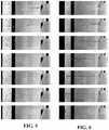
- Figure 5 includes a series of photographs showing with stop-motion photography, the delivery of a 6.5 ⁇ L ⁇ dose of water purified by reverse osmosis with methylene blue dye using a prior art nozzle with a pump.
- the nozzle includes a 0.45466 cm (.179 inch) liquid pathway which diverges to an outlet having a diameter of 0.127508 cm (.0502 inches) with an internal tip radius of 0.0127 cm (.005 inches).
- Figure 6 includes a series of photographs showing with stop-motion photography, the delivery of a 19.8 ⁇ L ⁇ dose of water purified by reverse osmosis with methylene blue dye using a nozzle formed in accordance with the subject invention and using the same type of pump as discussed with respect to Figure 5 .
- the nozzle here includes a 0.8001 cm (.315 inch) liquid pathway converging from a inlet of 0.09906 cm (.039 inches) to an outlet of 0.09144 cm (.036 inches) with the outlet having no internal tip radius.
- the liquid pathway is hydrophobically treated.
- the dose delivered with the nozzle in Figure 6 is more directed than with the prior art nozzle of Figure 5 . It is noted that the dose in Figure 6 has some break-up into smaller drops. However, overall dose is delivered more intact as a single unit with the nozzle of Figure 6 as compared with the dose of Figure 5 . This aides in delivering a maximum amount of a dose. Further to the extent a dose breaks up, the smaller drops maintain better linearity in being delivered by the nozzle of Figure 6 as compared with the delivery of the dose of Figure 5 . This results in a greater amount of dose reaching a target site.
Description
- This invention relates to nozzles for ophthalmic dispensers.
- Various dispensers for delivering medicament, and other active ingredients, to the eye are known in the prior art. Eye droppers and dropper bottles are used extensively to deliver liquid doses to the eyes of patients. Typical droppers and dropper bottles can only produce dose volumes of certain sizes, with no ability to provide smaller doses. As such, it is well recognized that a large percentage of administered ophthalmic liquid that is administered topically is lost by drainage, either externally or through nasolacrimal drainage.
- Dispensers have been developed in the prior art which can generate dose sizes in much smaller volumes than those provided by typical droppers and dropper bottles, such doses being in the range of 5-15 microliters. Dispensers for delivering such doses are known in the prior art, such as
U.S. Patent No. 5,152,435, which issued October 6, 1992 ;U.S. Patent No. 5,881,956, which issued March 16, 1999 ;U.S. Patent No. 6,513,682, which issued February 4, 2003 ;U.S. Patent No. 6,854,622, which issued February 15, 2005 ;U.S. Patent No. 6,991,137, which issued on January 31, 2006 ;U.S. Patent No. 7,014,068, which issued on March 21, 2006 ;U.S. Patent No. 7,073,733, which issued on July 11, 2006 ;U.S. Patent No. 7,131,559, which issued on November 7, 2006 ;U.S. Patent No. 7,207,468, which issued on April 24, 2007 ;U.S. Patent No. 7,261,224, which issued on August 28, 2007 ; andU.S. Patent No. 7,651,011, which issued on January 26, 2010 . - The aforesaid dispensers may achieve microdosing with doses in the range of 5-15 microliters. With such microdosing, concerns exist over repeatability within a target range. With such small doses, slight variability impacts the dose size.
-
EP-A-2332438 describes a nozzle .for applying powder into the human hair. -
US-A-2002/0084290 describes a wetting-resistant nozzle for dispensing small volumes of liquids. The nozzle comprises an internal flowpath, and an external surface that recedes from the discharge point at an angle greater than 90 degrees. - A nozzle is provided herein for ophthalmic dispensers which is configured to accommodate microdosing. The nozzle includes a converging pathway. Preferably, the pathway converges so as to impart momentum to liquid passing therethrough through an increase of velocity. A tapered portion may be provided flared openly from the inlet to best accept liquid flow thereinto and provide a funneling effect into the flowpath. Preferably, the flowpath terminates at an outlet which is internally un-radiused and circumscribed by a chamfered surface.
- To further enhance the ability of the nozzle to administer repeated uniform doses, one or more of the liquid-contacting surfaces is treated to be hydrophobic. Additionally, surfaces surrounding liquid-contacting surfaces may be also treated to be hydrophobic.
- Advantageously, with the subject invention, a nozzle is provided which can direct a dose for administration, with minimal attraction to the nozzle.
- These and other features of the invention will be better understood through a study of the following detailed description and accompanying drawings.
-
-
Figure 1 is a front perspective view of a nozzle formed in accordance with the subject invention; -
Figure 2 is a rear elevational view of a nozzle formed in accordance with the subject invention; -
Figure 3 is a side elevational view of a nozzle formed in accordance with the subject invention; -
Figure 4 is a cross-sectional view taken along line 4-4 ofFigure 3 ; -
Figure 5 is a series of stop-motion photographs showing delivery of a dose by a prior art nozzle; and -
Figure 6 is a series of stop-motion photographs showing delivery of a dose by a nozzle formed in accordance with the subject invention. - With reference to the Figures, a
nozzle 10 is provided. Thenozzle 10 is particularly well-suited for administering microdoses, e.g., ophthalmic doses in the range of 5-15, even 5-20, microliters. - As shown in the Figures, the
nozzle 10 is preferably a unitary piece manufactured separately from other components, such as pump components. Preferably, thenozzle 10 is formed from thermoplastic material and is preferably formed by molding. By being separately formed, the tolerances of thenozzle 10 may be tightly controlled. Although less preferred, thenozzle 10 may be formed integrally with other components of a pump. - The
nozzle 10 includes an elongated,tubular nozzle portion 12 which defines aliquid pathway 14 therethrough. Theliquid pathway 14 extends between aninlet 16 and anoutlet 18 so that liquid introduced through theinlet 16 may pass to theoutlet 18 through theliquid pathway 14. - The
liquid pathway 14 is elongated having a length 1 which is more than eight times greater than diameter d1 of theoutlet 18. The length 1 may be more than ten times greater than diameter d1 of theoutlet 18. Theliquid pathway 14 is formed to be convergent from theinlet 16 to theoutlet 18. With this arrangement, liquid passing through theliquid pathway 14 experiences a momentum buildup through an increase of velocity while travelling from theinlet 16 to theoutlet 18. The momentum buildup allows for a dose to be delivered at a higher velocity. This allows for the dose to be delivered in a more compact, less broken-up manner. Ideally, a dose of a singe drop is delivered. If sufficient momentum is not imparted, microbubbles form in the liquid with the dose possibly breaking up to some extent. - Preferably, the convergence is only slight so that the flow characteristics of the liquid passing through the
liquid pathway 14 are only slightly altered. In addition, fluid turbulence is minimized. It is preferred that the convergence be at a constant rate from theinlet 16 to theoutlet 18. The angle of convergence α is in the range of .25-1.0 degrees relative to the longitudinal axis CL of theliquid pathway 14. With the convergent arrangement of theliquid pathway 14, theinlet 16 is provided with a larger diameter than theoutlet 18. Preferably, the ratio of the diameter d2 of theinlet 16 to the diameter d1 of theoutlet 18 is in the range of 1.05-1.6, more preferably 1.05-1.5, more preferably 1.05-1.4, more preferably 1.05-1.3, more preferably 1.05-1.2, more preferably 1.05-1.1, and most preferably 1.08. - Preferably, a
tapered portion 20 extends, and diverges away, from theinlet 16. This provides an enlarged opening to receive liquid which is then funneled through thetapered portion 20 into theliquid pathway 14. Thetapered portion 20 includes aninner edge 22 which preferably extends continuously from theinlet 16. Theinner edge 22 is defined with the taper of thetapered portion 20. The taper may be provided with theinner edge 22 being arcuate, chamfered and combinations thereof. Surface interruptions such as straight wall portions or ledges may be provided on theinner edge 22, particularly if such enhances manufacturability. With thetapered portion 20, an overall decrease in diameter towards theinlet 16 is provided, such decrease in diameter being continuous or discontinuous. - The
tapered portion 20 also desirably may reduce vorticity imparted to the liquid as being delivered through thenozzle 10. Changes in direction in flow may cause liquid to have vorticity, which can also lead to dose break-up. A laminar flow is ideally sought. With typical pump arrangements, liquid is caused to significantly change direction (e.g., a 90° change in direction) in being fed from a fluid path and into a nozzle. A significant change in direction may impart vorticity. The taperedportion 20 may ameliorate this effect by allowing the liquid to traverse a tapered inlet into thenozzle 10 with a more gradual change of direction being applied than if notapered portion 20 was provided. This is more advantageous where an inlet fluid path is positioned at a generally right angle relative to thenozzle 10. - It is also preferred that the
nozzle portion 12 be formed with theoutlet 18 being internally un-radiused (theoutlet 18 lying wholly in a plane perpendicular to the longitudinal axis CL) and with a reduceddiameter section 24 about theoutlet 18. As shown in the Figures, the reduceddiameter section 24 preferably is a chamfered section which extends from theoutlet 18 and flares inwardly therefrom so as to minimize portions of thenozzle portion 12 being within a plane coinciding with the outlet 18 (the plane being perpendicular to the longitudinal axis CL). With this arrangement, a liquid dose discharged from theoutlet 18 will have minimal surface contact with thenozzle portion 12 about theoutlet 18. - To further enhance the ability of the
nozzle 10 to administer repeated uniform doses of liquid, theliquid pathway 14 is treated to be hydrophobic. Various techniques may be utilized for hydrophobic treatment, including plasma treatment. In this manner, capillary, or other attraction, may be minimized between thenozzle 10 and the dose. Such attractive force may disrupt the dose during delivery. Portions surrounding theliquid pathway 14, such as the taperedportion 20 and the reduceddiameter section 24, may be also hydrophobically treated. It may be most practical to treat theentire nozzle 10 hydrophobically. - To permit mounting of the
nozzle portion 12, a mountingring 26 may extend from thenozzle portion 12. Preferably, the mountingring 26 is bowl-shaped. The mountingring 26 circumscribes thenozzle portion 12 such that the outlet end of thenozzle portion 12 is on the inner side of the bowl of the mountingring 26. Preferably, a portion of thenozzle portion 12 extends rearwardly from the mountingring 26 so that theinlet 16 is spaced from the mountingring 26. It is also preferred that theoutlet 18 extend beyond the mountingring 26 so as to be located exteriorly thereof (e.g., theoutlet 18 is located beyondrim 28 of the mounting ring 26). -
Figure 5 includes a series of photographs showing with stop-motion photography, the delivery of a 6.5 µL· dose of water purified by reverse osmosis with methylene blue dye using a prior art nozzle with a pump. The nozzle includes a 0.45466 cm (.179 inch) liquid pathway which diverges to an outlet having a diameter of 0.127508 cm (.0502 inches) with an internal tip radius of 0.0127 cm (.005 inches). -
Figure 6 includes a series of photographs showing with stop-motion photography, the delivery of a 19.8 µL· dose of water purified by reverse osmosis with methylene blue dye using a nozzle formed in accordance with the subject invention and using the same type of pump as discussed with respect toFigure 5 . The nozzle here includes a 0.8001 cm (.315 inch) liquid pathway converging from a inlet of 0.09906 cm (.039 inches) to an outlet of 0.09144 cm (.036 inches) with the outlet having no internal tip radius. In addition, the liquid pathway is hydrophobically treated. - As can be seen, the dose delivered with the nozzle in
Figure 6 is more directed than with the prior art nozzle ofFigure 5 . It is noted that the dose inFigure 6 has some break-up into smaller drops. However, overall dose is delivered more intact as a single unit with the nozzle ofFigure 6 as compared with the dose ofFigure 5 . This aides in delivering a maximum amount of a dose. Further to the extent a dose breaks up, the smaller drops maintain better linearity in being delivered by the nozzle ofFigure 6 as compared with the delivery of the dose ofFigure 5 . This results in a greater amount of dose reaching a target site.
Claims (12)
- A nozzle (10) for ophthalmic dispensers, the nozzle comprising:a nozzle portion (12) defining a liquid pathway (14) extending between an inlet (16) and an outlet (18), said liquid pathway (14) converging from said inlet (16) to said outlet (18);wherein a length (1) is defined between said inlet (16) and said outlet (18), said length (1) being more than eight times greater than the diameter (d1) of said outlet (18), wherein a longitudinal axis (CL) extends along said liquid pathway (14), said liquid pathway (14) converging along the length (1) at an angle of convergence (α) in the range of .25 - 1.0 degrees relative to said longitudinal axis (CL); wherein said liquid pathway (14) is treated to be hydrophobic.
- A nozzle (10) as in claim 1, wherein the ratio of the diameter (d2) of said inlet (16) to the diameter (d1) of said outlet (18) is in one of the ranges of 1.05 - 1.6, 1.05 - 1.5, 1.05 - 1.4, 1.05 - 1.3, 1.05 - 1.2 and 1.05 - 1.1.
- A nozzle (10) as in claim 1, further comprising a tapered portion (20) extending, and diverging away, from said inlet (16).
- A nozzle (10) as in claim 3, wherein said tapered portion (20) includes an inner edge (22) which extends continuously from said inlet (16), wherein said inner edge (22) is provided with a shape selected from the group consisting of arcuate, chamfered, and combinations thereof.
- A nozzle (10) as in claim 1, further comprising a reduced diameter section (24) about said outlet (18), wherein said reduced diameter section (24) includes a chamfered section which extends from said outlet (18) and flares inwardly therefrom.
- A nozzle (10) as in claim 1, further comprising a mounting ring (26) extending from said nozzle portion (12).
- A nozzle (10) as in claim 6, wherein said mounting ring (26) is generally bowl-shaped.
- A nozzle (10) as in claim 7, wherein said outlet (18) is located on an inner side of the bowl shape of said mounting ring (26).
- A nozzle (10) as in claim 8, wherein said outlet (18) extends beyond said mounting ring (26).
- A nozzle (10) as in claim 7, wherein said inlet (16) is spaced from said mounting ring (26).
- A nozzle (10) as in claim 1, wherein the nozzle (10) is unitary or formed of thermoplastic material.
- A nozzle (10) as in claim 1, wherein said outlet (18) is internally un-radiused.
Applications Claiming Priority (2)
| Application Number | Priority Date | Filing Date | Title |
|---|---|---|---|
| US201261610138P | 2012-03-13 | 2012-03-13 | |
| PCT/US2013/030882 WO2013138466A1 (en) | 2012-03-13 | 2013-03-13 | Nozzle |
Publications (3)
| Publication Number | Publication Date |
|---|---|
| EP2825475A1 EP2825475A1 (en) | 2015-01-21 |
| EP2825475A4 EP2825475A4 (en) | 2015-10-07 |
| EP2825475B1 true EP2825475B1 (en) | 2020-09-02 |
Family
ID=49161766
Family Applications (1)
| Application Number | Title | Priority Date | Filing Date |
|---|---|---|---|
| EP13760868.3A Active EP2825475B1 (en) | 2012-03-13 | 2013-03-13 | Nozzle |
Country Status (3)
| Country | Link |
|---|---|
| US (2) | US10667943B2 (en) |
| EP (1) | EP2825475B1 (en) |
| WO (1) | WO2013138466A1 (en) |
Cited By (1)
| Publication number | Priority date | Publication date | Assignee | Title |
|---|---|---|---|---|
| WO2024044388A1 (en) * | 2022-08-25 | 2024-02-29 | Twenty Twenty Therapeutics Llc | Nozzle for an ophthalmic fluid delivery device |
Families Citing this family (7)
| Publication number | Priority date | Publication date | Assignee | Title |
|---|---|---|---|---|
| EP3496687B1 (en) | 2016-08-12 | 2020-05-20 | The Procter and Gamble Company | Method and apparatus for assembling absorbent articles |
| US10961028B1 (en) | 2017-03-15 | 2021-03-30 | Allen Brothers & Rosselot Inc. | Liquid dispenser for a bottle |
| US11203467B2 (en) | 2018-01-24 | 2021-12-21 | Nanodropper, Inc. | Assembly and method for delivery of micro-volume droplets from a squeeze bottle |
| KR20200112921A (en) | 2018-01-24 | 2020-10-05 | 나노드롭퍼 주식회사 | Assembly and method for providing micro-volume droplets from squeeze bottles |
| US10932947B2 (en) | 2018-04-11 | 2021-03-02 | Paul Enemark | Micro drop adapter for dropper bottles |
| US11872157B2 (en) | 2018-04-11 | 2024-01-16 | Nanodropper, Inc. | Micro drop adapter for dropper bottles |
| USD1017797S1 (en) | 2019-09-11 | 2024-03-12 | Nanodropper, Inc. | Microdrop dispensing adapter for eye dropper bottle |
Family Cites Families (21)
| Publication number | Priority date | Publication date | Assignee | Title |
|---|---|---|---|---|
| US4909801A (en) * | 1986-06-16 | 1990-03-20 | Acorn Laboratories, Inc. | Eyedrop dispenser having a bumper |
| US5007905A (en) * | 1990-02-20 | 1991-04-16 | Bauer George C | Eye drop applicator |
| US5221027A (en) * | 1991-02-20 | 1993-06-22 | Merck & Co., Inc. | Fluid dispenser tip with recessed dispensing nozzle |
| US5152435A (en) | 1991-06-13 | 1992-10-06 | Ben Zane Cohen | Ophthalmic dispensing pump |
| US5881956A (en) | 1996-08-08 | 1999-03-16 | Ben Z. Cohen | Microdispensing ophthalmic pump |
| US6105828A (en) * | 1998-04-22 | 2000-08-22 | Atrion Medical Products, Inc. | Non-bubble forming dropper tip |
| AU6272599A (en) | 1998-09-29 | 2000-04-17 | Ben Z. Cohen | Dispensing pump accessories for preventing the ingress of air and for aiding in alignment |
| US7014068B1 (en) | 1999-08-23 | 2006-03-21 | Ben Z. Cohen | Microdispensing pump |
| AU2002228864A1 (en) * | 2000-11-10 | 2002-05-21 | Therics, Inc. | A wetting-resistant nozzle for dispensing small volumes of liquid and a method for manufacturing a wetting-resistant nozzle |
| WO2002068317A1 (en) | 2001-02-21 | 2002-09-06 | Cohen Ben Z | Accurate dosing pump and accessories therefor |
| DE10112332C1 (en) * | 2001-03-13 | 2002-08-29 | Stella Kunststofftechnik Gmbh | Drip cap for dosing liquid in drop form and container with drip cap |
| US7651011B2 (en) | 2001-04-16 | 2010-01-26 | Ben Z. Cohen | Microdispensing pump |
| EP1404609B1 (en) | 2001-05-23 | 2011-08-31 | Cohen, Ben Z. | Accurate dosing pump |
| EP1436212B1 (en) | 2001-09-20 | 2009-07-01 | Ben Z. Cohen | Microdispensing pump |
| US20030197074A1 (en) * | 2002-04-17 | 2003-10-23 | Mcnerney Gerald J. | Spray nozzle attachment |
| US20060069358A1 (en) * | 2004-09-29 | 2006-03-30 | Gerondale Scott J | Controlled drop dispensing units |
| US20080039807A1 (en) * | 2006-08-08 | 2008-02-14 | Jerrold Scott Pine | Ophthalmic Drug Dispensing Tip |
| EP2070833B1 (en) * | 2007-12-14 | 2011-02-23 | The Procter & Gamble Company | Container with a device to prevent clogging of a dispensing device of the container |
| EP2332438A1 (en) * | 2009-12-14 | 2011-06-15 | KPSS-Kao Professional Salon Services GmbH | Nozzle for applying a powder |
| MX339173B (en) * | 2010-07-15 | 2016-05-12 | Corinthian Ophthalmic Inc | Drop generating device. |
| IE20110394A1 (en) * | 2010-09-07 | 2013-01-02 | Univ Limerick | A liquid droplet dispenser |
-
2013
- 2013-03-13 US US14/385,224 patent/US10667943B2/en active Active
- 2013-03-13 EP EP13760868.3A patent/EP2825475B1/en active Active
- 2013-03-13 WO PCT/US2013/030882 patent/WO2013138466A1/en active Application Filing
-
2020
- 2020-06-01 US US16/889,303 patent/US20200360182A1/en active Pending
Non-Patent Citations (1)
| Title |
|---|
| None * |
Cited By (1)
| Publication number | Priority date | Publication date | Assignee | Title |
|---|---|---|---|---|
| WO2024044388A1 (en) * | 2022-08-25 | 2024-02-29 | Twenty Twenty Therapeutics Llc | Nozzle for an ophthalmic fluid delivery device |
Also Published As
| Publication number | Publication date |
|---|---|
| EP2825475A4 (en) | 2015-10-07 |
| US20150038925A1 (en) | 2015-02-05 |
| US20200360182A1 (en) | 2020-11-19 |
| WO2013138466A1 (en) | 2013-09-19 |
| US10667943B2 (en) | 2020-06-02 |
| EP2825475A1 (en) | 2015-01-21 |
Similar Documents
| Publication | Publication Date | Title |
|---|---|---|
| US20200360182A1 (en) | Nozzle | |
| JP6433964B2 (en) | Nebulizer for nasal treatment | |
| JP6514277B2 (en) | Device for suction and mixing channel for device for suction | |
| US8807457B2 (en) | Push-button for a system for dispensing a product under pressure | |
| WO2006096654A3 (en) | Microject devices and methods for drug delivery | |
| KR102361964B1 (en) | Spray nozzle, in particular for a system for dispensing a pressurized fluid provided with a pushbutton, and dispensing system comprising such a nozzle | |
| US20100019067A1 (en) | Shower head | |
| WO2004041338A1 (en) | Inhalers | |
| US6123070A (en) | Device for enhancing the emptying of an inhaler metering chamber | |
| KR20220097884A (en) | Nozzle spray/spray nozzles and rest items for drip | |
| CN109070109A (en) | With the spraying improvement swirl nozzle component of the mist of the uniform droplet of efficient mechanical decomposition generation | |
| CN106345044A (en) | Cavity atomizing dosing device | |
| US20080228162A1 (en) | Single-use ampoule | |
| CN103977490A (en) | Medical atomizer | |
| CN113543746A (en) | Dual spray nozzle tip assembly | |
| KR20160070105A (en) | Device for delivery of an aerosol substance | |
| KR20220129647A (en) | Nozzles for dispensing liquids in the form of mists | |
| RU2644115C2 (en) | Control device and dispensing device | |
| JPH03111052A (en) | Liquid drop-distributing tip | |
| ITBS20030075U1 (en) | NEBULIZING NEEDLE WITH BLAST CHILLER PARTICLES ABUSTER | |
| ES2423831T3 (en) | Push button for a pressure product distribution system | |
| CN107297288B (en) | Nozzle for a system for dispensing a pressurized fluid and dispensing system comprising such a nozzle | |
| KR20020090410A (en) | Nozzle | |
| WO2008002616A3 (en) | Angled ophthalmic dropper tip | |
| WO2012008429A9 (en) | Disposable fluid discharge member for discharging fluid in desired state from inside container from inside container |
Legal Events
| Date | Code | Title | Description |
|---|---|---|---|
| PUAI | Public reference made under article 153(3) epc to a published international application that has entered the european phase |
Free format text: ORIGINAL CODE: 0009012 |
|
| 17P | Request for examination filed |
Effective date: 20140924 |
|
| AK | Designated contracting states |
Kind code of ref document: A1 Designated state(s): AL AT BE BG CH CY CZ DE DK EE ES FI FR GB GR HR HU IE IS IT LI LT LU LV MC MK MT NL NO PL PT RO RS SE SI SK SM TR |
|
| AX | Request for extension of the european patent |
Extension state: BA ME |
|
| DAX | Request for extension of the european patent (deleted) | ||
| RA4 | Supplementary search report drawn up and despatched (corrected) |
Effective date: 20150908 |
|
| RIC1 | Information provided on ipc code assigned before grant |
Ipc: B65D 47/18 20060101AFI20150902BHEP Ipc: A61F 9/00 20060101ALI20150902BHEP |
|
| STAA | Information on the status of an ep patent application or granted ep patent |
Free format text: STATUS: EXAMINATION IS IN PROGRESS |
|
| 17Q | First examination report despatched |
Effective date: 20181023 |
|
| GRAP | Despatch of communication of intention to grant a patent |
Free format text: ORIGINAL CODE: EPIDOSNIGR1 |
|
| STAA | Information on the status of an ep patent application or granted ep patent |
Free format text: STATUS: GRANT OF PATENT IS INTENDED |
|
| INTG | Intention to grant announced |
Effective date: 20200317 |
|
| GRAS | Grant fee paid |
Free format text: ORIGINAL CODE: EPIDOSNIGR3 |
|
| GRAA | (expected) grant |
Free format text: ORIGINAL CODE: 0009210 |
|
| STAA | Information on the status of an ep patent application or granted ep patent |
Free format text: STATUS: THE PATENT HAS BEEN GRANTED |
|
| AK | Designated contracting states |
Kind code of ref document: B1 Designated state(s): AL AT BE BG CH CY CZ DE DK EE ES FI FR GB GR HR HU IE IS IT LI LT LU LV MC MK MT NL NO PL PT RO RS SE SI SK SM TR |
|
| REG | Reference to a national code |
Ref country code: GB Ref legal event code: FG4D |
|
| REG | Reference to a national code |
Ref country code: AT Ref legal event code: REF Ref document number: 1308571 Country of ref document: AT Kind code of ref document: T Effective date: 20200915 Ref country code: CH Ref legal event code: EP |
|
| REG | Reference to a national code |
Ref country code: DE Ref legal event code: R096 Ref document number: 602013072163 Country of ref document: DE |
|
| REG | Reference to a national code |
Ref country code: IE Ref legal event code: FG4D |
|
| REG | Reference to a national code |
Ref country code: LT Ref legal event code: MG4D |
|
| PG25 | Lapsed in a contracting state [announced via postgrant information from national office to epo] |
Ref country code: NO Free format text: LAPSE BECAUSE OF FAILURE TO SUBMIT A TRANSLATION OF THE DESCRIPTION OR TO PAY THE FEE WITHIN THE PRESCRIBED TIME-LIMIT Effective date: 20201202 Ref country code: GR Free format text: LAPSE BECAUSE OF FAILURE TO SUBMIT A TRANSLATION OF THE DESCRIPTION OR TO PAY THE FEE WITHIN THE PRESCRIBED TIME-LIMIT Effective date: 20201203 Ref country code: BG Free format text: LAPSE BECAUSE OF FAILURE TO SUBMIT A TRANSLATION OF THE DESCRIPTION OR TO PAY THE FEE WITHIN THE PRESCRIBED TIME-LIMIT Effective date: 20201202 Ref country code: HR Free format text: LAPSE BECAUSE OF FAILURE TO SUBMIT A TRANSLATION OF THE DESCRIPTION OR TO PAY THE FEE WITHIN THE PRESCRIBED TIME-LIMIT Effective date: 20200902 Ref country code: SE Free format text: LAPSE BECAUSE OF FAILURE TO SUBMIT A TRANSLATION OF THE DESCRIPTION OR TO PAY THE FEE WITHIN THE PRESCRIBED TIME-LIMIT Effective date: 20200902 Ref country code: FI Free format text: LAPSE BECAUSE OF FAILURE TO SUBMIT A TRANSLATION OF THE DESCRIPTION OR TO PAY THE FEE WITHIN THE PRESCRIBED TIME-LIMIT Effective date: 20200902 Ref country code: LT Free format text: LAPSE BECAUSE OF FAILURE TO SUBMIT A TRANSLATION OF THE DESCRIPTION OR TO PAY THE FEE WITHIN THE PRESCRIBED TIME-LIMIT Effective date: 20200902 |
|
| REG | Reference to a national code |
Ref country code: NL Ref legal event code: MP Effective date: 20200902 |
|
| REG | Reference to a national code |
Ref country code: AT Ref legal event code: MK05 Ref document number: 1308571 Country of ref document: AT Kind code of ref document: T Effective date: 20200902 |
|
| PG25 | Lapsed in a contracting state [announced via postgrant information from national office to epo] |
Ref country code: PL Free format text: LAPSE BECAUSE OF FAILURE TO SUBMIT A TRANSLATION OF THE DESCRIPTION OR TO PAY THE FEE WITHIN THE PRESCRIBED TIME-LIMIT Effective date: 20200902 Ref country code: RS Free format text: LAPSE BECAUSE OF FAILURE TO SUBMIT A TRANSLATION OF THE DESCRIPTION OR TO PAY THE FEE WITHIN THE PRESCRIBED TIME-LIMIT Effective date: 20200902 Ref country code: LV Free format text: LAPSE BECAUSE OF FAILURE TO SUBMIT A TRANSLATION OF THE DESCRIPTION OR TO PAY THE FEE WITHIN THE PRESCRIBED TIME-LIMIT Effective date: 20200902 |
|
| PG25 | Lapsed in a contracting state [announced via postgrant information from national office to epo] |
Ref country code: CZ Free format text: LAPSE BECAUSE OF FAILURE TO SUBMIT A TRANSLATION OF THE DESCRIPTION OR TO PAY THE FEE WITHIN THE PRESCRIBED TIME-LIMIT Effective date: 20200902 Ref country code: EE Free format text: LAPSE BECAUSE OF FAILURE TO SUBMIT A TRANSLATION OF THE DESCRIPTION OR TO PAY THE FEE WITHIN THE PRESCRIBED TIME-LIMIT Effective date: 20200902 Ref country code: NL Free format text: LAPSE BECAUSE OF FAILURE TO SUBMIT A TRANSLATION OF THE DESCRIPTION OR TO PAY THE FEE WITHIN THE PRESCRIBED TIME-LIMIT Effective date: 20200902 Ref country code: PT Free format text: LAPSE BECAUSE OF FAILURE TO SUBMIT A TRANSLATION OF THE DESCRIPTION OR TO PAY THE FEE WITHIN THE PRESCRIBED TIME-LIMIT Effective date: 20210104 Ref country code: RO Free format text: LAPSE BECAUSE OF FAILURE TO SUBMIT A TRANSLATION OF THE DESCRIPTION OR TO PAY THE FEE WITHIN THE PRESCRIBED TIME-LIMIT Effective date: 20200902 Ref country code: SM Free format text: LAPSE BECAUSE OF FAILURE TO SUBMIT A TRANSLATION OF THE DESCRIPTION OR TO PAY THE FEE WITHIN THE PRESCRIBED TIME-LIMIT Effective date: 20200902 |
|
| PG25 | Lapsed in a contracting state [announced via postgrant information from national office to epo] |
Ref country code: IS Free format text: LAPSE BECAUSE OF FAILURE TO SUBMIT A TRANSLATION OF THE DESCRIPTION OR TO PAY THE FEE WITHIN THE PRESCRIBED TIME-LIMIT Effective date: 20210102 Ref country code: AL Free format text: LAPSE BECAUSE OF FAILURE TO SUBMIT A TRANSLATION OF THE DESCRIPTION OR TO PAY THE FEE WITHIN THE PRESCRIBED TIME-LIMIT Effective date: 20200902 Ref country code: AT Free format text: LAPSE BECAUSE OF FAILURE TO SUBMIT A TRANSLATION OF THE DESCRIPTION OR TO PAY THE FEE WITHIN THE PRESCRIBED TIME-LIMIT Effective date: 20200902 Ref country code: ES Free format text: LAPSE BECAUSE OF FAILURE TO SUBMIT A TRANSLATION OF THE DESCRIPTION OR TO PAY THE FEE WITHIN THE PRESCRIBED TIME-LIMIT Effective date: 20200902 |
|
| REG | Reference to a national code |
Ref country code: DE Ref legal event code: R097 Ref document number: 602013072163 Country of ref document: DE |
|
| PG25 | Lapsed in a contracting state [announced via postgrant information from national office to epo] |
Ref country code: SK Free format text: LAPSE BECAUSE OF FAILURE TO SUBMIT A TRANSLATION OF THE DESCRIPTION OR TO PAY THE FEE WITHIN THE PRESCRIBED TIME-LIMIT Effective date: 20200902 |
|
| PLBE | No opposition filed within time limit |
Free format text: ORIGINAL CODE: 0009261 |
|
| STAA | Information on the status of an ep patent application or granted ep patent |
Free format text: STATUS: NO OPPOSITION FILED WITHIN TIME LIMIT |
|
| 26N | No opposition filed |
Effective date: 20210603 |
|
| PG25 | Lapsed in a contracting state [announced via postgrant information from national office to epo] |
Ref country code: SI Free format text: LAPSE BECAUSE OF FAILURE TO SUBMIT A TRANSLATION OF THE DESCRIPTION OR TO PAY THE FEE WITHIN THE PRESCRIBED TIME-LIMIT Effective date: 20200902 Ref country code: DK Free format text: LAPSE BECAUSE OF FAILURE TO SUBMIT A TRANSLATION OF THE DESCRIPTION OR TO PAY THE FEE WITHIN THE PRESCRIBED TIME-LIMIT Effective date: 20200902 |
|
| PG25 | Lapsed in a contracting state [announced via postgrant information from national office to epo] |
Ref country code: MC Free format text: LAPSE BECAUSE OF FAILURE TO SUBMIT A TRANSLATION OF THE DESCRIPTION OR TO PAY THE FEE WITHIN THE PRESCRIBED TIME-LIMIT Effective date: 20200902 Ref country code: IT Free format text: LAPSE BECAUSE OF FAILURE TO SUBMIT A TRANSLATION OF THE DESCRIPTION OR TO PAY THE FEE WITHIN THE PRESCRIBED TIME-LIMIT Effective date: 20200902 |
|
| REG | Reference to a national code |
Ref country code: CH Ref legal event code: PL |
|
| REG | Reference to a national code |
Ref country code: BE Ref legal event code: MM Effective date: 20210331 |
|
| PG25 | Lapsed in a contracting state [announced via postgrant information from national office to epo] |
Ref country code: IE Free format text: LAPSE BECAUSE OF NON-PAYMENT OF DUE FEES Effective date: 20210313 Ref country code: CH Free format text: LAPSE BECAUSE OF NON-PAYMENT OF DUE FEES Effective date: 20210331 Ref country code: LI Free format text: LAPSE BECAUSE OF NON-PAYMENT OF DUE FEES Effective date: 20210331 Ref country code: LU Free format text: LAPSE BECAUSE OF NON-PAYMENT OF DUE FEES Effective date: 20210313 |
|
| PG25 | Lapsed in a contracting state [announced via postgrant information from national office to epo] |
Ref country code: BE Free format text: LAPSE BECAUSE OF NON-PAYMENT OF DUE FEES Effective date: 20210331 |
|
| PGFP | Annual fee paid to national office [announced via postgrant information from national office to epo] |
Ref country code: FR Payment date: 20230320 Year of fee payment: 11 |
|
| PG25 | Lapsed in a contracting state [announced via postgrant information from national office to epo] |
Ref country code: HU Free format text: LAPSE BECAUSE OF FAILURE TO SUBMIT A TRANSLATION OF THE DESCRIPTION OR TO PAY THE FEE WITHIN THE PRESCRIBED TIME-LIMIT; INVALID AB INITIO Effective date: 20130313 |
|
| PGFP | Annual fee paid to national office [announced via postgrant information from national office to epo] |
Ref country code: GB Payment date: 20230323 Year of fee payment: 11 Ref country code: DE Payment date: 20230316 Year of fee payment: 11 |
|
| PG25 | Lapsed in a contracting state [announced via postgrant information from national office to epo] |
Ref country code: CY Free format text: LAPSE BECAUSE OF FAILURE TO SUBMIT A TRANSLATION OF THE DESCRIPTION OR TO PAY THE FEE WITHIN THE PRESCRIBED TIME-LIMIT Effective date: 20200902 |