EP2824683A1 - Cleaning device for contamination of contact of electromagnetic contactor - Google Patents
Cleaning device for contamination of contact of electromagnetic contactor Download PDFInfo
- Publication number
- EP2824683A1 EP2824683A1 EP14152694.7A EP14152694A EP2824683A1 EP 2824683 A1 EP2824683 A1 EP 2824683A1 EP 14152694 A EP14152694 A EP 14152694A EP 2824683 A1 EP2824683 A1 EP 2824683A1
- Authority
- EP
- European Patent Office
- Prior art keywords
- electromagnetic contactor
- housing
- rotating plate
- contact portion
- contaminants
- Prior art date
- Legal status (The legal status is an assumption and is not a legal conclusion. Google has not performed a legal analysis and makes no representation as to the accuracy of the status listed.)
- Granted
Links
Images



Classifications
-
- B—PERFORMING OPERATIONS; TRANSPORTING
- B08—CLEANING
- B08B—CLEANING IN GENERAL; PREVENTION OF FOULING IN GENERAL
- B08B7/00—Cleaning by methods not provided for in a single other subclass or a single group in this subclass
-
- B—PERFORMING OPERATIONS; TRANSPORTING
- B08—CLEANING
- B08B—CLEANING IN GENERAL; PREVENTION OF FOULING IN GENERAL
- B08B1/00—Cleaning by methods involving the use of tools
- B08B1/30—Cleaning by methods involving the use of tools by movement of cleaning members over a surface
- B08B1/32—Cleaning by methods involving the use of tools by movement of cleaning members over a surface using rotary cleaning members
- B08B1/36—Cleaning by methods involving the use of tools by movement of cleaning members over a surface using rotary cleaning members rotating about an axis orthogonal to the surface
-
- H—ELECTRICITY
- H01—ELECTRIC ELEMENTS
- H01H—ELECTRIC SWITCHES; RELAYS; SELECTORS; EMERGENCY PROTECTIVE DEVICES
- H01H1/00—Contacts
- H01H1/60—Auxiliary means structurally associated with the switch for cleaning or lubricating contact-making surfaces
- H01H1/605—Cleaning of contact-making surfaces by relatively high voltage pulses
-
- H—ELECTRICITY
- H01—ELECTRIC ELEMENTS
- H01H—ELECTRIC SWITCHES; RELAYS; SELECTORS; EMERGENCY PROTECTIVE DEVICES
- H01H50/00—Details of electromagnetic relays
- H01H50/02—Bases; Casings; Covers
- H01H50/04—Mounting complete relay or separate parts of relay on a base or inside a case
- H01H50/041—Details concerning assembly of relays
- H01H50/045—Details particular to contactors
-
- H—ELECTRICITY
- H01—ELECTRIC ELEMENTS
- H01H—ELECTRIC SWITCHES; RELAYS; SELECTORS; EMERGENCY PROTECTIVE DEVICES
- H01H9/00—Details of switching devices, not covered by groups H01H1/00 - H01H7/00
- H01H9/30—Means for extinguishing or preventing arc between current-carrying parts
- H01H9/44—Means for extinguishing or preventing arc between current-carrying parts using blow-out magnet
- H01H9/443—Means for extinguishing or preventing arc between current-carrying parts using blow-out magnet using permanent magnets
-
- H—ELECTRICITY
- H10—SEMICONDUCTOR DEVICES; ELECTRIC SOLID-STATE DEVICES NOT OTHERWISE PROVIDED FOR
- H10P—GENERIC PROCESSES OR APPARATUS FOR THE MANUFACTURE OR TREATMENT OF DEVICES COVERED BY CLASS H10
- H10P52/00—Grinding, lapping or polishing of wafers, substrates or parts of devices
-
- H—ELECTRICITY
- H01—ELECTRIC ELEMENTS
- H01H—ELECTRIC SWITCHES; RELAYS; SELECTORS; EMERGENCY PROTECTIVE DEVICES
- H01H50/00—Details of electromagnetic relays
- H01H50/54—Contact arrangements
- H01H50/546—Contact arrangements for contactors having bridging contacts
Definitions
- the present invention relates to a device for cleaning contaminants on a contact portion of an electromagnetic contactor, and more particularly, a device for cleaning contaminants on a contact portion of an electromagnetic contactor in which a magnetic force the acting direction of which is changed in time is generated to the outside of the electromagnetic contactor for cleaning contaminants generated at a contact portion thereof with an arc extinguishing method, thereby effectively and broadly performing the cleaning of contaminants.
- electromagnetic contactor is a type of electrical circuit switching device for transferring a mechanical drive and current signal using the principle of an electromagnet, and provided in various industrial facilities, machines, vehicles, and the like.
- FIG. 1 is a longitudinal cross-sectional view illustrating an electromagnetic contactor in the related art used in electric vehicles.
- the configuration of an electromagnetic contactor for electric vehicles may include a case 1, a housing 2, a stationary contact point 3 and a movable contact point 4, and typically further include electrical actuators 5, 6, 7, 8 for driving the movable contact point 4 to control the switching of contact points by an electrical signal.
- Contaminants are adhered to the contact portion (a stationary contact point and a movable contact point) of the electromagnetic contactor.
- the contaminants may increase a contact resistance of the contact portion and thus a surface thereof can be clearly maintained through a cleaning or conditioning operation.
- FIG. 2 is a view illustrating an operation diagram according to the cleaning method.
- FIG. 2 is a transverse cross-sectional view illustrating a contact portion of an electromagnetic contactor in the related art.
- a magnetic body for arc extinction 9 is provided in a direction perpendicular to the stationary contact point 3 and movable contact point 4.
- An arc is generated in such a form that it is started from any one (indicated by ⁇ ) of the stationary contact point 3 and enters into the other one (indicated by ⁇ ) of the stationary contact point 3 while forming an arc shape.
- the ⁇ indicated electrode receives a force (F) exerted in the " ⁇ " direction and ⁇ indicated electrode receives a force (F') in the " ⁇ ” direction, thereby cleaning contaminants on a surface of the electrode.
- the acting direction of a magnetic force (B) is fixed in a predetermined direction so as to generate the magnetic force (B) due to the magnetic body for arc extinction 9 fixed and provided within the electromagnetic contactor and thus forces (F, F') generated on the arc is also exerted only in a particular direction (horizontal direction ( ⁇ or ⁇ ) in FIG. 2 ), and as a result, the cleaning range of contaminants is restricted, thereby causing a problem in which there is a limit in the cleaning performance.
- the present invention is contrived to solve the foregoing problems, and an aspect of the present invention is to provide a device for cleaning contaminants on a contact portion of an electromagnetic contactor in which a magnetic force the acting direction of which is changed in time is generated to the outside of the electromagnetic contactor for cleaning contaminants generated at a contact portion thereof with an arc extinguishing method, thereby effectively and broadly performing the cleaning of contaminants.
- a device for cleaning contaminants on a contact portion of an electromagnetic contactor may include a housing; a drive unit provided within the housing to generate a driving force; a rotating plate rotatably provided within the housing to be rotated by receiving the driving force; and a magnetic body coupled to both end portions of the rotating plate, respectively, to generate a magnetic force exerted from one side to the other side.
- a drive motor may be provided in the drive unit.
- a driven gear may be coupled to a central shaft of the rotating plate, and the driven gear may be teeth combined with a driving gear of the drive motor to receive a rotational force of the drive motor so as to rotate the rotating plate.
- the device may further include a controller configured to control the rotational speed of the drive motor so as to adjust the rotational speed, rotational direction and rotation angle of the rotating plate.
- a device for cleaning contaminants on a contact portion of an electromagnetic contactor may further include a support provided at a lower portion of the housing to accommodate an electromagnetic contactor therein.
- the support may be height adjustable.
- a magnetic force the acting direction of which is changed in time may be generated to the outside of the electromagnetic contactor, thereby effectively performing the cleaning of contaminants on the contact portion thereof due to an arc extinction method.
- a device for cleaning contaminants on a contact portion of an electromagnetic contactor may include a housing 10; a drive unit provided within the housing 10 to generate a driving force; a rotating plate 30 rotatably provided within the housing 10 to be rotated by receiving the driving force; a magnetic body 50 coupled to both end portions 31 of the rotating plate 30, respectively, to generate a magnetic force exerted from one side to the other side; and a plurality of supports 70 provided at a lower portion of the housing 10 to accommodate an electromagnetic contactor therein.
- FIG. 3 is a perspective view illustrating a device for cleaning contaminants on a contact portion of an electromagnetic contactor according to the present disclosure
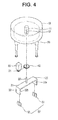
- FIG. 4 is an exploded perspective view of FIG. 4 .
- a device for cleaning contaminants on a contact portion of an electromagnetic contactor according to an embodiment of the present invention will be described in detail with reference to the drawings.
- the housing 10 is formed in a substantially cylindrical shape with an opening lower portion.
- the upper surface of the housing 10 is formed with an area capable of accommodating an electromagnetic contactor, and the height thereof is formed with a predetermined length capable of accommodating a drive unit and a magnetic body 50 which will be described later.
- the housing 10 may be formed of a synthetic resin material due to molding injection.
- a supporting shaft 11 may be formed in a protruded manner at a central portion of the housing 10 to rotatably support the central shaft 33 of the rotating plate 30 which will be described later.
- a coupling groove 12 capable of fixing the central shaft 33 of the rotating plate 30 may be formed along a length direction thereof at the supporting shaft 11.
- the drive unit is provided within the housing 10.
- the drive unit provides a rotational force to the rotating plate 30 which will be described later.
- a drive motor 20 may be provided in the drive unit.
- the drive motor 20 may be provided with an AC motor or DC motor to be suitable to a power source, and provided with a motor integrated with a reduction gear to adjust the rotational speed of the driving gear 21.
- the rotating plate 30 is configured with a body portion 31 and a vane portion 32.
- the body portion 31 may be formed with a long rectangular plate shape.
- the central shaft 33 is vertically formed in a protruded manner at the center of the body portion 31.
- the central shaft 33 of the rotating plate 30 is inserted and combined with the coupling groove 12 of the supporting shaft 11 in the housing 10 and thus the rotating plate 30 is rotatably provided in the housing 10.
- a bearing (not shown) may be interposed between the central shaft 33 and the coupling groove 12 to smoothly rotate the central shaft 33 of the rotating plate 30 with the support within the supporting shaft 11 of the housing 10.
- the vane portions 32 of the rotating plate 30 are formed to be bent and extended in a vertically downward direction at both end portions of the body portion 31. Accordingly, the vane portions 32 vertically formed at both end portions of the body portion 31, respectively, are formed in the shape of facing each other.
- the vane portion 32 may be formed of the same material as that of the body portion 31.
- the driven gear 40 is inserted into the central shaft 33.
- the driven gear 40 is fixed and coupled to the central shaft 33 of the rotating plate 30.
- the driven gear 40 is teeth combined with the driving gear 21 of the drive motor 20 to receive a rotational force of the drive motor 20 so as to rotate the rotating plate 30.
- the magnetic body 50 is coupled to an inner lateral surface of the vane portion 32.
- An N-pole magnetic body 51 is adhered to one vane portion 32a, and a S-pole magnetic body 52 is adhered to the other vane portion 32b to generate a magnetic field (B) exerted from the one vane portion 32a to the other vane portion 32b.
- the controller 60 may be provided in part of the housing 10.
- the controller 60 may be formed with a PCB board.
- the controller 60 may control the rotational speed of the drive motor 20 to control the rotational speed, rotational direction, rotation angle and the like of the rotating plate 30.
- a scheme for adjusting the voltage of the power source received at the drive motor 20 from the power supply unit may be used.
- the controller 60 may control the rotation angle of the rotating plate 30, thereby placing the vane portion 32 of the rotating plate 30 at a specific location. Accordingly, it may be possible to adjust the direction of a magnetic field (B) generated from the magnetic body 50.
- B magnetic field
- the drive motor 20 may be formed with a stepper motor.
- the stepper motor may be rotated according to a preset angle even when an additional driven gear 40 or controller 60 is not provided therein, and accordingly, the rotating plate 30 may be sequentially rotated at a predetermined angle.
- a plurality of supports 70 may be formed at a lower portion of the housing 10 to support the housing 10 while being separated from the ground.
- the support 70 may merely perform the role of a pedestal.
- the support 70 may be formed to be height adjustable. As an example, it is illustrated the support 70 formed in an inscribed slide manner such as antennas or camera tripods. An electromagnetic contactor with various sizes may be accommodated therein by adjusting the height of the support 70.
- An electromagnetic contactor 100 subject to the operation of cleaning contaminants is placed at a lower portion of the housing 10.
- the height of the support 70 is adjusted to place a portion having a stationary contact point 103 and a movable contact point 104 at the height of the N-pole and S-pole magnetic bodies 51, 52.
- Power is supplied to the device, and power is also supplied to the electromagnetic contactor 100 to generate an arc.
- the arc generated from the electromagnetic contactor 100 is generated in such a form that it is started from any one (indicated by ⁇ ) of the stationary contact point 103 and enters into another one (indicated by ⁇ ) of the stationary contact point 103 while forming an arc shape.
- the arc receives forces (F, F') according to a magnetic force (B) generated from the N-pole and S-pole magnetic bodies 51, 52 to clean contaminants adhered to the contact portion.
- the operation of the controller 60 allows the rotating plate 30 to be rotated by each predetermined angle according to a change of time (for example, sequentially rotated with the location of ⁇ in FIG. 5 ), and the direction of the magnetic force (B) generated from the N-pole and S-pole magnetic bodies 51, 52 is also varied (changed in a clockwise direction based on the direction from the top to bottom in the example of FIG. 5 ).
- the direction of forces (F, F') received by an arc is also varied according to a change of the direction of the magnetic field (B), and thus the forces (F, F') are exerted on the entire surface of the stationary contact point 103 and movable contact point 104 to effectively clean contaminants.
- a magnetic force (B) generated from the N-pole and S-pole magnetic bodies 51, 52 is added to a magnetic force generated from the magnetic body for arc extinction 105 provided within the electromagnetic contactor 100 to determine the resultant direction of the magnetic force (B).
- a magnetic force (B) generated from the N-pole and S-pole magnetic bodies 51, 52 is formed to be highly greater than that from the magnetic body for arc extinction 105, the resultant direction of the magnetic force (B) is substantially identical to the direction of a magnetic field (B) generated from the N-pole and S-pole magnetic bodies 51, 52.
Landscapes
- Physics & Mathematics (AREA)
- Electromagnetism (AREA)
- Cleaning In General (AREA)
- Arc-Extinguishing Devices That Are Switches (AREA)
- Contacts (AREA)
Abstract
Description
- The present invention relates to a device for cleaning contaminants on a contact portion of an electromagnetic contactor, and more particularly, a device for cleaning contaminants on a contact portion of an electromagnetic contactor in which a magnetic force the acting direction of which is changed in time is generated to the outside of the electromagnetic contactor for cleaning contaminants generated at a contact portion thereof with an arc extinguishing method, thereby effectively and broadly performing the cleaning of contaminants.
- In general, electromagnetic contactor is a type of electrical circuit switching device for transferring a mechanical drive and current signal using the principle of an electromagnet, and provided in various industrial facilities, machines, vehicles, and the like.
FIG. 1 is a longitudinal cross-sectional view illustrating an electromagnetic contactor in the related art used in electric vehicles. The configuration of an electromagnetic contactor for electric vehicles may include a case 1, a housing 2, astationary contact point 3 and amovable contact point 4, and typically further includeelectrical actuators movable contact point 4 to control the switching of contact points by an electrical signal. - Contaminants are adhered to the contact portion (a stationary contact point and a movable contact point) of the electromagnetic contactor. The contaminants may increase a contact resistance of the contact portion and thus a surface thereof can be clearly maintained through a cleaning or conditioning operation.
- A conventional method used for the cleaning operation has been carried out in such a manner that an arc is artificially generated on the contact portion to burn contaminants existing on an electrode surface thereof.
FIG. 2 is a view illustrating an operation diagram according to the cleaning method.FIG. 2 is a transverse cross-sectional view illustrating a contact portion of an electromagnetic contactor in the related art. A magnetic body forarc extinction 9 is provided in a direction perpendicular to thestationary contact point 3 andmovable contact point 4. An arc is generated in such a form that it is started from any one (indicated by □) of thestationary contact point 3 and enters into the other one (indicated by □) of thestationary contact point 3 while forming an arc shape. Here, a magnetic force (B) flowing from the top to bottom on the drawing is generated, and an arc is formed with the flow of a current (I) and thus a force according to the Fleming's left hand rule (F = B x I) is generated between thestationary contact point 3 andmovable contact point 4. Accordingly, the □ indicated electrode receives a force (F) exerted in the "→" direction and □ indicated electrode receives a force (F') in the "←" direction, thereby cleaning contaminants on a surface of the electrode. - However, according to a contaminant cleaning method in the related art, the acting direction of a magnetic force (B) is fixed in a predetermined direction so as to generate the magnetic force (B) due to the magnetic body for
arc extinction 9 fixed and provided within the electromagnetic contactor and thus forces (F, F') generated on the arc is also exerted only in a particular direction (horizontal direction (← or → ) inFIG. 2 ), and as a result, the cleaning range of contaminants is restricted, thereby causing a problem in which there is a limit in the cleaning performance. - The present invention is contrived to solve the foregoing problems, and an aspect of the present invention is to provide a device for cleaning contaminants on a contact portion of an electromagnetic contactor in which a magnetic force the acting direction of which is changed in time is generated to the outside of the electromagnetic contactor for cleaning contaminants generated at a contact portion thereof with an arc extinguishing method, thereby effectively and broadly performing the cleaning of contaminants.
- A device for cleaning contaminants on a contact portion of an electromagnetic contactor according to an embodiment of the present invention may include a housing; a drive unit provided within the housing to generate a driving force; a rotating plate rotatably provided within the housing to be rotated by receiving the driving force; and a magnetic body coupled to both end portions of the rotating plate, respectively, to generate a magnetic force exerted from one side to the other side.
- Here, a drive motor may be provided in the drive unit.
- Furthermore, a driven gear may be coupled to a central shaft of the rotating plate, and the driven gear may be teeth combined with a driving gear of the drive motor to receive a rotational force of the drive motor so as to rotate the rotating plate.
- Furthermore, the device may further include a controller configured to control the rotational speed of the drive motor so as to adjust the rotational speed, rotational direction and rotation angle of the rotating plate.
- On the other hand, a device for cleaning contaminants on a contact portion of an electromagnetic contactor according to an embodiment of the present invention may further include a support provided at a lower portion of the housing to accommodate an electromagnetic contactor therein.
- Furthermore, the support may be height adjustable.
- According to a device for cleaning contaminants on a contact portion of an electromagnetic contactor in accordance with the present invention, a magnetic force the acting direction of which is changed in time may be generated to the outside of the electromagnetic contactor, thereby effectively performing the cleaning of contaminants on the contact portion thereof due to an arc extinction method.
- The accompanying drawings, which are included to provide a further understanding of the invention and are incorporated in and constitute a part of this specification, illustrate embodiments of the invention and together with the description serve to explain the principles of the invention.
- In the drawings:
-
FIG. 1 is a longitudinal cross-sectional view illustrating an inner portion of an electromagnetic contactor according to the related art; -
FIG. 2 is a transverse cross-sectional view illustrating a method of cleaning contaminants on a contact portion of an electromagnetic contactor according to the related art; -
FIG. 3 is a perspective view illustrating a device for cleaning contaminants on a contact portion of an electromagnetic contactor according to the present disclosure; -
FIG. 4 is an exploded perspective view ofFIG. 4 ; and -
FIG. 5 is a transverse cross-sectional view illustrating the operation status of a device for cleaning contaminants on a contact portion of an electromagnetic contactor according to the present disclosure. - Hereinafter, a preferred embodiment of the present invention will be described in detail with reference to the accompanying drawings to such an extent that the present invention can be easily implemented by a person having ordinary skill in the art to which the present invention pertains, but it does not mean that the technical concept and scope of the present invention are limited due to this.
- A device for cleaning contaminants on a contact portion of an electromagnetic contactor according to an embodiment of the present invention may include a
housing 10; a drive unit provided within thehousing 10 to generate a driving force; arotating plate 30 rotatably provided within thehousing 10 to be rotated by receiving the driving force; amagnetic body 50 coupled to bothend portions 31 of therotating plate 30, respectively, to generate a magnetic force exerted from one side to the other side; and a plurality ofsupports 70 provided at a lower portion of thehousing 10 to accommodate an electromagnetic contactor therein. -
FIG. 3 is a perspective view illustrating a device for cleaning contaminants on a contact portion of an electromagnetic contactor according to the present disclosure, andFIG. 4 is an exploded perspective view ofFIG. 4 . A device for cleaning contaminants on a contact portion of an electromagnetic contactor according to an embodiment of the present invention will be described in detail with reference to the drawings. - The
housing 10 is formed in a substantially cylindrical shape with an opening lower portion. The upper surface of thehousing 10 is formed with an area capable of accommodating an electromagnetic contactor, and the height thereof is formed with a predetermined length capable of accommodating a drive unit and amagnetic body 50 which will be described later. Thehousing 10 may be formed of a synthetic resin material due to molding injection. A supportingshaft 11 may be formed in a protruded manner at a central portion of thehousing 10 to rotatably support thecentral shaft 33 of the rotatingplate 30 which will be described later. Acoupling groove 12 capable of fixing thecentral shaft 33 of the rotatingplate 30 may be formed along a length direction thereof at the supportingshaft 11. - The drive unit is provided within the
housing 10. The drive unit provides a rotational force to the rotatingplate 30 which will be described later. Adrive motor 20 may be provided in the drive unit. Thedrive motor 20 may be provided with an AC motor or DC motor to be suitable to a power source, and provided with a motor integrated with a reduction gear to adjust the rotational speed of thedriving gear 21. - The rotating
plate 30 is configured with abody portion 31 and avane portion 32. Thebody portion 31 may be formed with a long rectangular plate shape. Thecentral shaft 33 is vertically formed in a protruded manner at the center of thebody portion 31. Thecentral shaft 33 of the rotatingplate 30 is inserted and combined with thecoupling groove 12 of the supportingshaft 11 in thehousing 10 and thus the rotatingplate 30 is rotatably provided in thehousing 10. Here, a bearing (not shown) may be interposed between thecentral shaft 33 and thecoupling groove 12 to smoothly rotate thecentral shaft 33 of the rotatingplate 30 with the support within the supportingshaft 11 of thehousing 10. - The
vane portions 32 of the rotatingplate 30 are formed to be bent and extended in a vertically downward direction at both end portions of thebody portion 31. Accordingly, thevane portions 32 vertically formed at both end portions of thebody portion 31, respectively, are formed in the shape of facing each other. Thevane portion 32 may be formed of the same material as that of thebody portion 31. - The driven
gear 40 is inserted into thecentral shaft 33. The drivengear 40 is fixed and coupled to thecentral shaft 33 of the rotatingplate 30. The drivengear 40 is teeth combined with thedriving gear 21 of thedrive motor 20 to receive a rotational force of thedrive motor 20 so as to rotate therotating plate 30. - The
magnetic body 50 is coupled to an inner lateral surface of thevane portion 32. An N-polemagnetic body 51 is adhered to onevane portion 32a, and a S-polemagnetic body 52 is adhered to theother vane portion 32b to generate a magnetic field (B) exerted from the onevane portion 32a to theother vane portion 32b. - The
controller 60 may be provided in part of thehousing 10. Thecontroller 60 may be formed with a PCB board. Thecontroller 60 may control the rotational speed of thedrive motor 20 to control the rotational speed, rotational direction, rotation angle and the like of therotating plate 30. As a method of controlling the rotational speed of thedrive motor 20, a scheme for adjusting the voltage of the power source received at thedrive motor 20 from the power supply unit may be used. Thecontroller 60 may control the rotation angle of therotating plate 30, thereby placing thevane portion 32 of therotating plate 30 at a specific location. Accordingly, it may be possible to adjust the direction of a magnetic field (B) generated from themagnetic body 50. - On the other hand, according to another embodiment, the
drive motor 20 may be formed with a stepper motor. In this case, the stepper motor may be rotated according to a preset angle even when an additional drivengear 40 orcontroller 60 is not provided therein, and accordingly, the rotatingplate 30 may be sequentially rotated at a predetermined angle. - A plurality of
supports 70 may be formed at a lower portion of thehousing 10 to support thehousing 10 while being separated from the ground. Thesupport 70 may merely perform the role of a pedestal. According to another embodiment, thesupport 70 may be formed to be height adjustable. As an example, it is illustrated thesupport 70 formed in an inscribed slide manner such as antennas or camera tripods. An electromagnetic contactor with various sizes may be accommodated therein by adjusting the height of thesupport 70. - The operation of a device for cleaning contaminants on a contact portion of an electromagnetic contactor according to an embodiment of the present invention will be described with reference to
FIG. 5 . - An
electromagnetic contactor 100 subject to the operation of cleaning contaminants is placed at a lower portion of thehousing 10. The height of thesupport 70 is adjusted to place a portion having astationary contact point 103 and amovable contact point 104 at the height of the N-pole and S-polemagnetic bodies - Power is supplied to the device, and power is also supplied to the
electromagnetic contactor 100 to generate an arc. The arc generated from theelectromagnetic contactor 100 is generated in such a form that it is started from any one (indicated by □) of thestationary contact point 103 and enters into another one (indicated by □) of thestationary contact point 103 while forming an arc shape. The arc receives forces (F, F') according to a magnetic force (B) generated from the N-pole and S-polemagnetic bodies - The operation of the
controller 60 allows therotating plate 30 to be rotated by each predetermined angle according to a change of time (for example, sequentially rotated with the location of □→□→©→□→□→□ inFIG. 5 ), and the direction of the magnetic force (B) generated from the N-pole and S-polemagnetic bodies FIG. 5 ). The direction of forces (F, F') received by an arc is also varied according to a change of the direction of the magnetic field (B), and thus the forces (F, F') are exerted on the entire surface of thestationary contact point 103 andmovable contact point 104 to effectively clean contaminants. - A magnetic force (B) generated from the N-pole and S-pole
magnetic bodies electromagnetic contactor 100 to determine the resultant direction of the magnetic force (B). Here, when a magnetic force (B) generated from the N-pole and S-polemagnetic bodies magnetic bodies - Although the present invention has been described with reference to the foregoing preferred embodiments, it will be easily recognized by those skilled in the art that various modifications and changes can be made without departing from the gist and scope of the invention, and it should be also clearly understood that all these modifications and changes fall in the appended claims.
Claims (6)
- A device for cleaning contaminants on a contact portion of an electromagnetic contactor, the device comprising:a housing 10;a drive unit provided within the housing 10 to generate a driving force;a rotating plate 30 rotatably provided within the housing 10 to be rotated by receiving the driving force; anda magnetic body 50 coupled to both end portions 31 of the rotating plate 30, respectively, to generate a magnetic force exerted from one side to the other side.
- The device of claim 1, wherein a drive motor 20 is provided in the drive unit.
- The device of claim 2, wherein a driven gear 40 is coupled to a central shaft 33 of the rotating plate 30, and the driven gear 40 is teeth combined with a driving gear 21 of the drive motor 20 to receive a rotational force of the drive motor 20 so as to rotate the rotating plate 30.
- The device of claims 2-3, further comprising:a controller 60 configured to control the rotational speed of the drive motor 20 so as to adjust the rotational speed, rotational direction and rotation angle of the rotating plate 30.
- The device according to any one of the preceding claims, further comprising:a support 70 provided at a lower portion of the housing 10 to accommodate an electromagnetic contactor 100 therein.
- The device of claim 6, wherein the support 70 is height adjustable.
Applications Claiming Priority (1)
| Application Number | Priority Date | Filing Date | Title |
|---|---|---|---|
| KR1020130079885A KR102099359B1 (en) | 2013-07-08 | 2013-07-08 | Cleaning Device for Contamination of Contact of Electromagnetic Contactor |
Publications (2)
| Publication Number | Publication Date |
|---|---|
| EP2824683A1 true EP2824683A1 (en) | 2015-01-14 |
| EP2824683B1 EP2824683B1 (en) | 2017-01-04 |
Family
ID=50028824
Family Applications (1)
| Application Number | Title | Priority Date | Filing Date |
|---|---|---|---|
| EP14152694.7A Active EP2824683B1 (en) | 2013-07-08 | 2014-01-27 | Cleaning device for contamination of contact of electromagnetic contactor |
Country Status (6)
| Country | Link |
|---|---|
| US (1) | US9452455B2 (en) |
| EP (1) | EP2824683B1 (en) |
| JP (1) | JP5676791B2 (en) |
| KR (1) | KR102099359B1 (en) |
| CN (1) | CN104275331B (en) |
| ES (1) | ES2620006T3 (en) |
Cited By (1)
| Publication number | Priority date | Publication date | Assignee | Title |
|---|---|---|---|---|
| KR20220029216A (en) * | 2020-09-01 | 2022-03-08 | 주식회사 엘지에너지솔루션 | Relay and battery comprising the same |
Families Citing this family (10)
| Publication number | Priority date | Publication date | Assignee | Title |
|---|---|---|---|---|
| KR102257575B1 (en) * | 2015-05-20 | 2021-05-31 | 삼성전자주식회사 | Display driver integrated circuit |
| JP6892810B2 (en) * | 2017-10-02 | 2021-06-23 | 富士通コンポーネント株式会社 | Electromagnetic relay |
| JP2021514827A (en) | 2018-02-23 | 2021-06-17 | インターナショナル テスト ソリューションズ, インコーポレイテッド | Flexible electronic circuits New materials and hardware for automatically cleaning web rolls |
| US10792713B1 (en) * | 2019-07-02 | 2020-10-06 | International Test Solutions, Inc. | Pick and place machine cleaning system and method |
| US11756811B2 (en) | 2019-07-02 | 2023-09-12 | International Test Solutions, Llc | Pick and place machine cleaning system and method |
| US11318550B2 (en) | 2019-11-14 | 2022-05-03 | International Test Solutions, Llc | System and method for cleaning wire bonding machines using functionalized surface microfeatures |
| US11035898B1 (en) | 2020-05-11 | 2021-06-15 | International Test Solutions, Inc. | Device and method for thermal stabilization of probe elements using a heat conducting wafer |
| CN114334548B (en) * | 2022-03-10 | 2022-05-20 | 东莞市元则电器有限公司 | Contact self-cleaning self-locking relay and contact cleaning method thereof |
| CN114975013B (en) * | 2022-05-27 | 2025-01-10 | 杭州申发电气有限公司 | A high-precision travel monitoring system for circuit breakers |
| CN115254800B (en) * | 2022-07-15 | 2023-06-13 | 业泓科技(成都)有限公司 | Probe cleaning device and probe cleaning method |
Citations (4)
| Publication number | Priority date | Publication date | Assignee | Title |
|---|---|---|---|---|
| US4134026A (en) * | 1976-06-11 | 1979-01-09 | Ricoh Company, Ltd. | Mechanical switch circuit comprising contact conditioning means |
| CN87201238U (en) * | 1987-04-13 | 1987-12-30 | 龚金和 | Arc suppressing self-cleaning type control button |
| EP1168392A1 (en) * | 1999-10-14 | 2002-01-02 | Matsushita Electric Works, Ltd. | Contactor |
| US20120181953A1 (en) * | 2011-01-14 | 2012-07-19 | GM Global Technology Operations LLC | Dual bipolar magnetic field for rotary high-voltage contactor in automotive lithium-ion battery systems |
Family Cites Families (15)
| Publication number | Priority date | Publication date | Assignee | Title |
|---|---|---|---|---|
| US4395695A (en) * | 1980-07-25 | 1983-07-26 | Copal Company Limited | Non-contact magnetic potentiometer |
| FR2682808B1 (en) | 1991-10-17 | 1997-01-24 | Merlin Gerin | HYBRID CIRCUIT BREAKER WITH AXIAL BLOWING COIL. |
| JP2002163968A (en) * | 2000-11-27 | 2002-06-07 | Matsushita Electric Works Ltd | Oxide film removing method of dc-driving electromagnetic relay |
| US7113063B2 (en) * | 2002-03-18 | 2006-09-26 | Cellnet Innovations, Inc. | Rotation sensing |
| US7772830B2 (en) * | 2006-03-03 | 2010-08-10 | Texas Instruments Incorporated | Test handler automatic contactor cleaner methods and surrogate cleaning device |
| KR100632849B1 (en) * | 2006-05-10 | 2006-10-16 | (주)리텍테크놀러지 | Cleaning device with non-contact power transmission means |
| US8371316B2 (en) * | 2009-12-03 | 2013-02-12 | International Test Solutions, Inc. | Apparatuses, device, and methods for cleaning tester interface contact elements and support hardware |
| CN201985041U (en) * | 2011-03-10 | 2011-09-21 | 二一三电器深圳有限公司 | Nonpolar direct-current contactor arc extinguishing system |
| JP5085755B2 (en) * | 2011-03-15 | 2012-11-28 | オムロン株式会社 | Electromagnetic relay |
| JP2012199113A (en) * | 2011-03-22 | 2012-10-18 | Panasonic Corp | Contact device and electromagnetic switch |
| US9309603B2 (en) * | 2011-09-14 | 2016-04-12 | Applied Materials, Inc | Component cleaning in a metal plating apparatus |
| JP5876270B2 (en) * | 2011-11-01 | 2016-03-02 | 富士電機株式会社 | Magnetic contactor |
| CN102592881B (en) | 2011-12-09 | 2015-07-15 | 沈阳工业大学 | Disc type laminated gyromagnetic transversely-blowing vacuum arc extinguishing chamber |
| JP2013190550A (en) * | 2012-03-13 | 2013-09-26 | Fuji Xerox Co Ltd | Cleaning device and image forming device using the same |
| CN202487498U (en) * | 2012-03-21 | 2012-10-10 | 温州市明达电器有限公司 | Bidirectional magnetic field arc extinction device |
-
2013
- 2013-07-08 KR KR1020130079885A patent/KR102099359B1/en active Active
-
2014
- 2014-01-27 EP EP14152694.7A patent/EP2824683B1/en active Active
- 2014-01-27 ES ES14152694.7T patent/ES2620006T3/en active Active
- 2014-01-27 US US14/165,166 patent/US9452455B2/en active Active
- 2014-02-13 JP JP2014025510A patent/JP5676791B2/en not_active Expired - Fee Related
- 2014-05-07 CN CN201410191013.1A patent/CN104275331B/en active Active
Patent Citations (4)
| Publication number | Priority date | Publication date | Assignee | Title |
|---|---|---|---|---|
| US4134026A (en) * | 1976-06-11 | 1979-01-09 | Ricoh Company, Ltd. | Mechanical switch circuit comprising contact conditioning means |
| CN87201238U (en) * | 1987-04-13 | 1987-12-30 | 龚金和 | Arc suppressing self-cleaning type control button |
| EP1168392A1 (en) * | 1999-10-14 | 2002-01-02 | Matsushita Electric Works, Ltd. | Contactor |
| US20120181953A1 (en) * | 2011-01-14 | 2012-07-19 | GM Global Technology Operations LLC | Dual bipolar magnetic field for rotary high-voltage contactor in automotive lithium-ion battery systems |
Cited By (2)
| Publication number | Priority date | Publication date | Assignee | Title |
|---|---|---|---|---|
| KR20220029216A (en) * | 2020-09-01 | 2022-03-08 | 주식회사 엘지에너지솔루션 | Relay and battery comprising the same |
| EP4174899A4 (en) * | 2020-09-01 | 2023-12-20 | LG Energy Solution, Ltd. | RELAY AND BATTERY SYSTEM INCLUDING THE LATTER |
Also Published As
| Publication number | Publication date |
|---|---|
| KR20150006280A (en) | 2015-01-16 |
| EP2824683B1 (en) | 2017-01-04 |
| ES2620006T3 (en) | 2017-06-27 |
| US20150013085A1 (en) | 2015-01-15 |
| KR102099359B1 (en) | 2020-04-09 |
| CN104275331B (en) | 2016-08-24 |
| JP2015018789A (en) | 2015-01-29 |
| US9452455B2 (en) | 2016-09-27 |
| CN104275331A (en) | 2015-01-14 |
| JP5676791B2 (en) | 2015-02-25 |
Similar Documents
| Publication | Publication Date | Title |
|---|---|---|
| EP2824683B1 (en) | Cleaning device for contamination of contact of electromagnetic contactor | |
| EP2691213B1 (en) | Forward/reverse switching device for power tools | |
| JP5224209B2 (en) | Two-dimensional resonant vibration motor | |
| CN108942565B (en) | Electric tool | |
| CN105246661B (en) | cordless circular saw | |
| EP2418667A3 (en) | Air circuit breaker | |
| JP2009071946A5 (en) | ||
| WO2015071638A3 (en) | An electronically controlled universal motor | |
| EP2996242A3 (en) | Drive circuit for a permanent magnetic motor | |
| CN112292722A (en) | information output device | |
| EP1826891A3 (en) | Control drive circuit for electric power tool | |
| BRPI0721896B1 (en) | ELECTROMAGNETIC SWITCHING DEVICE THAT HAS A MULTIPLE OF GRADUATE AREAS IN RELATION TO THE OTHER | |
| US8222559B2 (en) | Automatic soldering machine | |
| KR20110136439A (en) | Self-polishing device | |
| KR20160106288A (en) | machining tools table associated with electromagnetic chuck | |
| KR101419831B1 (en) | Driving apparatus having multi-degrees of freedom | |
| US20050139461A1 (en) | Portable Apparatus for the Remote Operation of a Pistol Grip Circuit Breaker Control Switch | |
| KR101830268B1 (en) | Switchgear unit having built-in electrical fuse | |
| JP2000270529A (en) | Electric motor | |
| CN215340193U (en) | Performance detection device suitable for Hall chip | |
| JP6464339B2 (en) | Power generator | |
| KR102189384B1 (en) | Apparatus for processing eye-glass lens | |
| CN113594789B (en) | Charging device and electronic device assembly | |
| CN104617703A (en) | Vibration motor | |
| PL1632017T3 (en) | Control device |
Legal Events
| Date | Code | Title | Description |
|---|---|---|---|
| 17P | Request for examination filed |
Effective date: 20140127 |
|
| AK | Designated contracting states |
Kind code of ref document: A1 Designated state(s): AL AT BE BG CH CY CZ DE DK EE ES FI FR GB GR HR HU IE IS IT LI LT LU LV MC MK MT NL NO PL PT RO RS SE SI SK SM TR |
|
| AX | Request for extension of the european patent |
Extension state: BA ME |
|
| PUAI | Public reference made under article 153(3) epc to a published international application that has entered the european phase |
Free format text: ORIGINAL CODE: 0009012 |
|
| R17P | Request for examination filed (corrected) |
Effective date: 20150707 |
|
| RBV | Designated contracting states (corrected) |
Designated state(s): AL AT BE BG CH CY CZ DE DK EE ES FI FR GB GR HR HU IE IS IT LI LT LU LV MC MK MT NL NO PL PT RO RS SE SI SK SM TR |
|
| GRAP | Despatch of communication of intention to grant a patent |
Free format text: ORIGINAL CODE: EPIDOSNIGR1 |
|
| RIC1 | Information provided on ipc code assigned before grant |
Ipc: H01H 1/60 20060101AFI20160708BHEP Ipc: B08B 7/00 20060101ALN20160708BHEP Ipc: H01H 50/54 20060101ALN20160708BHEP Ipc: H01H 50/04 20060101ALI20160708BHEP Ipc: H01H 9/44 20060101ALI20160708BHEP |
|
| RIC1 | Information provided on ipc code assigned before grant |
Ipc: H01H 9/44 20060101ALI20160718BHEP Ipc: H01H 50/54 20060101ALN20160718BHEP Ipc: H01H 50/04 20060101ALI20160718BHEP Ipc: H01H 1/60 20060101AFI20160718BHEP Ipc: B08B 7/00 20060101ALN20160718BHEP |
|
| INTG | Intention to grant announced |
Effective date: 20160801 |
|
| GRAS | Grant fee paid |
Free format text: ORIGINAL CODE: EPIDOSNIGR3 |
|
| STAA | Information on the status of an ep patent application or granted ep patent |
Free format text: STATUS: GRANT OF PATENT IS INTENDED |
|
| GRAA | (expected) grant |
Free format text: ORIGINAL CODE: 0009210 |
|
| STAA | Information on the status of an ep patent application or granted ep patent |
Free format text: STATUS: THE PATENT HAS BEEN GRANTED |
|
| AK | Designated contracting states |
Kind code of ref document: B1 Designated state(s): AL AT BE BG CH CY CZ DE DK EE ES FI FR GB GR HR HU IE IS IT LI LT LU LV MC MK MT NL NO PL PT RO RS SE SI SK SM TR |
|
| REG | Reference to a national code |
Ref country code: GB Ref legal event code: FG4D |
|
| REG | Reference to a national code |
Ref country code: CH Ref legal event code: EP |
|
| REG | Reference to a national code |
Ref country code: AT Ref legal event code: REF Ref document number: 859967 Country of ref document: AT Kind code of ref document: T Effective date: 20170115 |
|
| REG | Reference to a national code |
Ref country code: IE Ref legal event code: FG4D |
|
| REG | Reference to a national code |
Ref country code: FR Ref legal event code: PLFP Year of fee payment: 4 |
|
| REG | Reference to a national code |
Ref country code: DE Ref legal event code: R096 Ref document number: 602014005916 Country of ref document: DE |
|
| REG | Reference to a national code |
Ref country code: NL Ref legal event code: MP Effective date: 20170104 Ref country code: LT Ref legal event code: MG4D |
|
| PG25 | Lapsed in a contracting state [announced via postgrant information from national office to epo] |
Ref country code: BE Free format text: LAPSE BECAUSE OF NON-PAYMENT OF DUE FEES Effective date: 20170131 |
|
| REG | Reference to a national code |
Ref country code: AT Ref legal event code: MK05 Ref document number: 859967 Country of ref document: AT Kind code of ref document: T Effective date: 20170104 |
|
| REG | Reference to a national code |
Ref country code: ES Ref legal event code: FG2A Ref document number: 2620006 Country of ref document: ES Kind code of ref document: T3 Effective date: 20170627 |
|
| PG25 | Lapsed in a contracting state [announced via postgrant information from national office to epo] |
Ref country code: NL Free format text: LAPSE BECAUSE OF FAILURE TO SUBMIT A TRANSLATION OF THE DESCRIPTION OR TO PAY THE FEE WITHIN THE PRESCRIBED TIME-LIMIT Effective date: 20170104 |
|
| PG25 | Lapsed in a contracting state [announced via postgrant information from national office to epo] |
Ref country code: IS Free format text: LAPSE BECAUSE OF FAILURE TO SUBMIT A TRANSLATION OF THE DESCRIPTION OR TO PAY THE FEE WITHIN THE PRESCRIBED TIME-LIMIT Effective date: 20170504 Ref country code: LT Free format text: LAPSE BECAUSE OF FAILURE TO SUBMIT A TRANSLATION OF THE DESCRIPTION OR TO PAY THE FEE WITHIN THE PRESCRIBED TIME-LIMIT Effective date: 20170104 Ref country code: GR Free format text: LAPSE BECAUSE OF FAILURE TO SUBMIT A TRANSLATION OF THE DESCRIPTION OR TO PAY THE FEE WITHIN THE PRESCRIBED TIME-LIMIT Effective date: 20170405 Ref country code: FI Free format text: LAPSE BECAUSE OF FAILURE TO SUBMIT A TRANSLATION OF THE DESCRIPTION OR TO PAY THE FEE WITHIN THE PRESCRIBED TIME-LIMIT Effective date: 20170104 Ref country code: NO Free format text: LAPSE BECAUSE OF FAILURE TO SUBMIT A TRANSLATION OF THE DESCRIPTION OR TO PAY THE FEE WITHIN THE PRESCRIBED TIME-LIMIT Effective date: 20170404 Ref country code: HR Free format text: LAPSE BECAUSE OF FAILURE TO SUBMIT A TRANSLATION OF THE DESCRIPTION OR TO PAY THE FEE WITHIN THE PRESCRIBED TIME-LIMIT Effective date: 20170104 |
|
| PG25 | Lapsed in a contracting state [announced via postgrant information from national office to epo] |
Ref country code: RS Free format text: LAPSE BECAUSE OF FAILURE TO SUBMIT A TRANSLATION OF THE DESCRIPTION OR TO PAY THE FEE WITHIN THE PRESCRIBED TIME-LIMIT Effective date: 20170104 Ref country code: AT Free format text: LAPSE BECAUSE OF FAILURE TO SUBMIT A TRANSLATION OF THE DESCRIPTION OR TO PAY THE FEE WITHIN THE PRESCRIBED TIME-LIMIT Effective date: 20170104 Ref country code: LV Free format text: LAPSE BECAUSE OF FAILURE TO SUBMIT A TRANSLATION OF THE DESCRIPTION OR TO PAY THE FEE WITHIN THE PRESCRIBED TIME-LIMIT Effective date: 20170104 Ref country code: SE Free format text: LAPSE BECAUSE OF FAILURE TO SUBMIT A TRANSLATION OF THE DESCRIPTION OR TO PAY THE FEE WITHIN THE PRESCRIBED TIME-LIMIT Effective date: 20170104 Ref country code: PT Free format text: LAPSE BECAUSE OF FAILURE TO SUBMIT A TRANSLATION OF THE DESCRIPTION OR TO PAY THE FEE WITHIN THE PRESCRIBED TIME-LIMIT Effective date: 20170504 Ref country code: PL Free format text: LAPSE BECAUSE OF FAILURE TO SUBMIT A TRANSLATION OF THE DESCRIPTION OR TO PAY THE FEE WITHIN THE PRESCRIBED TIME-LIMIT Effective date: 20170104 Ref country code: BG Free format text: LAPSE BECAUSE OF FAILURE TO SUBMIT A TRANSLATION OF THE DESCRIPTION OR TO PAY THE FEE WITHIN THE PRESCRIBED TIME-LIMIT Effective date: 20170404 |
|
| REG | Reference to a national code |
Ref country code: CH Ref legal event code: PL |
|
| REG | Reference to a national code |
Ref country code: DE Ref legal event code: R097 Ref document number: 602014005916 Country of ref document: DE |
|
| PG25 | Lapsed in a contracting state [announced via postgrant information from national office to epo] |
Ref country code: EE Free format text: LAPSE BECAUSE OF FAILURE TO SUBMIT A TRANSLATION OF THE DESCRIPTION OR TO PAY THE FEE WITHIN THE PRESCRIBED TIME-LIMIT Effective date: 20170104 Ref country code: LI Free format text: LAPSE BECAUSE OF NON-PAYMENT OF DUE FEES Effective date: 20170131 Ref country code: CH Free format text: LAPSE BECAUSE OF NON-PAYMENT OF DUE FEES Effective date: 20170131 Ref country code: CZ Free format text: LAPSE BECAUSE OF FAILURE TO SUBMIT A TRANSLATION OF THE DESCRIPTION OR TO PAY THE FEE WITHIN THE PRESCRIBED TIME-LIMIT Effective date: 20170104 Ref country code: SK Free format text: LAPSE BECAUSE OF FAILURE TO SUBMIT A TRANSLATION OF THE DESCRIPTION OR TO PAY THE FEE WITHIN THE PRESCRIBED TIME-LIMIT Effective date: 20170104 Ref country code: RO Free format text: LAPSE BECAUSE OF FAILURE TO SUBMIT A TRANSLATION OF THE DESCRIPTION OR TO PAY THE FEE WITHIN THE PRESCRIBED TIME-LIMIT Effective date: 20170104 |
|
| REG | Reference to a national code |
Ref country code: IE Ref legal event code: MM4A |
|
| PLBE | No opposition filed within time limit |
Free format text: ORIGINAL CODE: 0009261 |
|
| STAA | Information on the status of an ep patent application or granted ep patent |
Free format text: STATUS: NO OPPOSITION FILED WITHIN TIME LIMIT |
|
| PG25 | Lapsed in a contracting state [announced via postgrant information from national office to epo] |
Ref country code: SM Free format text: LAPSE BECAUSE OF FAILURE TO SUBMIT A TRANSLATION OF THE DESCRIPTION OR TO PAY THE FEE WITHIN THE PRESCRIBED TIME-LIMIT Effective date: 20170104 Ref country code: MC Free format text: LAPSE BECAUSE OF FAILURE TO SUBMIT A TRANSLATION OF THE DESCRIPTION OR TO PAY THE FEE WITHIN THE PRESCRIBED TIME-LIMIT Effective date: 20170104 Ref country code: DK Free format text: LAPSE BECAUSE OF FAILURE TO SUBMIT A TRANSLATION OF THE DESCRIPTION OR TO PAY THE FEE WITHIN THE PRESCRIBED TIME-LIMIT Effective date: 20170104 Ref country code: LU Free format text: LAPSE BECAUSE OF NON-PAYMENT OF DUE FEES Effective date: 20170127 |
|
| REG | Reference to a national code |
Ref country code: FR Ref legal event code: PLFP Year of fee payment: 5 |
|
| REG | Reference to a national code |
Ref country code: BE Ref legal event code: MM Effective date: 20170131 |
|
| PG25 | Lapsed in a contracting state [announced via postgrant information from national office to epo] |
Ref country code: SI Free format text: LAPSE BECAUSE OF FAILURE TO SUBMIT A TRANSLATION OF THE DESCRIPTION OR TO PAY THE FEE WITHIN THE PRESCRIBED TIME-LIMIT Effective date: 20170104 Ref country code: IE Free format text: LAPSE BECAUSE OF NON-PAYMENT OF DUE FEES Effective date: 20170127 |
|
| PG25 | Lapsed in a contracting state [announced via postgrant information from national office to epo] |
Ref country code: MT Free format text: LAPSE BECAUSE OF NON-PAYMENT OF DUE FEES Effective date: 20170127 |
|
| PG25 | Lapsed in a contracting state [announced via postgrant information from national office to epo] |
Ref country code: HU Free format text: LAPSE BECAUSE OF FAILURE TO SUBMIT A TRANSLATION OF THE DESCRIPTION OR TO PAY THE FEE WITHIN THE PRESCRIBED TIME-LIMIT; INVALID AB INITIO Effective date: 20140127 |
|
| PG25 | Lapsed in a contracting state [announced via postgrant information from national office to epo] |
Ref country code: CY Free format text: LAPSE BECAUSE OF FAILURE TO SUBMIT A TRANSLATION OF THE DESCRIPTION OR TO PAY THE FEE WITHIN THE PRESCRIBED TIME-LIMIT Effective date: 20170104 |
|
| PG25 | Lapsed in a contracting state [announced via postgrant information from national office to epo] |
Ref country code: MK Free format text: LAPSE BECAUSE OF FAILURE TO SUBMIT A TRANSLATION OF THE DESCRIPTION OR TO PAY THE FEE WITHIN THE PRESCRIBED TIME-LIMIT Effective date: 20170104 |
|
| PG25 | Lapsed in a contracting state [announced via postgrant information from national office to epo] |
Ref country code: TR Free format text: LAPSE BECAUSE OF FAILURE TO SUBMIT A TRANSLATION OF THE DESCRIPTION OR TO PAY THE FEE WITHIN THE PRESCRIBED TIME-LIMIT Effective date: 20170104 |
|
| PGFP | Annual fee paid to national office [announced via postgrant information from national office to epo] |
Ref country code: GB Payment date: 20191223 Year of fee payment: 7 |
|
| PG25 | Lapsed in a contracting state [announced via postgrant information from national office to epo] |
Ref country code: AL Free format text: LAPSE BECAUSE OF FAILURE TO SUBMIT A TRANSLATION OF THE DESCRIPTION OR TO PAY THE FEE WITHIN THE PRESCRIBED TIME-LIMIT Effective date: 20170104 |
|
| GBPC | Gb: european patent ceased through non-payment of renewal fee |
Effective date: 20210127 |
|
| PG25 | Lapsed in a contracting state [announced via postgrant information from national office to epo] |
Ref country code: GB Free format text: LAPSE BECAUSE OF NON-PAYMENT OF DUE FEES Effective date: 20210127 |
|
| P01 | Opt-out of the competence of the unified patent court (upc) registered |
Effective date: 20230625 |
|
| PGFP | Annual fee paid to national office [announced via postgrant information from national office to epo] |
Ref country code: FR Payment date: 20241206 Year of fee payment: 12 |
|
| PGFP | Annual fee paid to national office [announced via postgrant information from national office to epo] |
Ref country code: DE Payment date: 20241205 Year of fee payment: 12 |
|
| PGFP | Annual fee paid to national office [announced via postgrant information from national office to epo] |
Ref country code: ES Payment date: 20250207 Year of fee payment: 12 |
|
| PGFP | Annual fee paid to national office [announced via postgrant information from national office to epo] |
Ref country code: IT Payment date: 20241206 Year of fee payment: 12 |