EP2824452A1 - Galvanic cell type oxygen sensor - Google Patents
Galvanic cell type oxygen sensor Download PDFInfo
- Publication number
- EP2824452A1 EP2824452A1 EP14176670.9A EP14176670A EP2824452A1 EP 2824452 A1 EP2824452 A1 EP 2824452A1 EP 14176670 A EP14176670 A EP 14176670A EP 2824452 A1 EP2824452 A1 EP 2824452A1
- Authority
- EP
- European Patent Office
- Prior art keywords
- oxygen
- sensor
- permeable membrane
- cell type
- galvanic cell
- Prior art date
- Legal status (The legal status is an assumption and is not a legal conclusion. Google has not performed a legal analysis and makes no representation as to the accuracy of the status listed.)
- Granted
Links
Images



Classifications
-
- G—PHYSICS
- G01—MEASURING; TESTING
- G01N—INVESTIGATING OR ANALYSING MATERIALS BY DETERMINING THEIR CHEMICAL OR PHYSICAL PROPERTIES
- G01N27/00—Investigating or analysing materials by the use of electric, electrochemical, or magnetic means
- G01N27/26—Investigating or analysing materials by the use of electric, electrochemical, or magnetic means by investigating electrochemical variables; by using electrolysis or electrophoresis
- G01N27/403—Cells and electrode assemblies
- G01N27/404—Cells with anode, cathode and cell electrolyte on the same side of a permeable membrane which separates them from the sample fluid, e.g. Clark-type oxygen sensors
Definitions
- the present invention relates to a galvanic cell type oxygen sensor including a positive electrode, a negative electrode, an electrolyte solution, and an oxygen permeable membrane.
- a galvanic cell type oxygen sensor including a positive electrode, a negative electrode, an electrolyte solution, and an oxygen permeable membrane is small and light, and is further operable at normal temperature and inexpensive.
- the sensor is used in various fields for the check of the state of oxygen deficiency in ship's holds and manholes, the detection of the concentration of oxygen in a medical instrument such as an anesthesia machine or an artificial respirator, and other purposes.
- Fig. 6 illustrates an ordinary sectional structure of a galvanic cell type oxygen sensor that has been hitherto put into various practical uses.
- reference number 1 represents a first holder lid (inner lid); 2, an O-ring; 3, a protective membrane for preventing the adhesion of rubbish and dust onto a first oxygen permeable membrane, and the adhesion of a water membrane thereto; 4A, the first oxygen permeable membrane; 4B, a catalyst electrode; 5, a positive current collector; 6, a positive leading wire; 7, an electrolyte solution; 8, a negative electrode; 9, a holder body; 10, a second holder lid (outer lid); 11, a bore through which the electrolyte solution is to be supplied; 12, a bore into which the leading wire is inserted; 13, a positive current collector holding region; 14, a correcting resistance; and 15, a temperature compensating thermistor.
- the catalyst electrode 4B and the positive current collector 5 constitute a positive electrode 45.
- the principle of the operation of the galvanic cell type oxygen sensor is as follows: Oxygen that has passed through the first oxygen permeable membrane 4A, through which oxygen is selectively caused to permeate, the amount of the permeation of oxygen being restricted in accordance with the reaction of the cell, is reduced in the catalyst electrode 4B, which is capable of reducing oxygen electrochemically, so that electrochemical reactions described below are caused between the catalyst electrode 4B and the negative electrode 8 by aid of the electrolyte solution 7.
- JP-A-07-190984 discloses a technique of wrapping an oxygen gas sensor with an oxygen gas barrier transparent film while sealing up a deoxidizer and an oxygen-detecting agent therein.
- the oxygen sensor is stored in a highly oxygen-free state, so that the consumption of the electrode material can be restrained.
- a reaction different from the above-mentioned reactions is unfavorably caused in its positive electrode.
- the sensor when the sensor is actually used, the sensor may be in an abnormal state.
- An object of the present invention is to provide a galvanic cell type oxygen sensor capable of restraining a different reaction as described above on its positive electrode while the electrode material thereof is restrained from being consumed.
- a first aspect of the galvanic cell type oxygen sensor according to the present invention is a sensor including a positive electrode, a negative electrode, an electrolyte solution, and a first oxygen permeable membrane, wherein the concentration of oxygen detected before ordinary use of the sensor is controlled into the range between 0.1% by volume or more and 4.0% by volume or less.
- a first aspect of the galvanic cell type oxygen sensor according to the present invention is a sensor including a positive electrode, a negative electrode, an electrolyte solution, and a first oxygen permeable membrane, wherein the concentration of oxygen detected before ordinary use of the sensor is controlled into the range between 0.1% by volume or more and 4.0% by volume or less.
- the control is preferably made through a second oxygen permeable membrane that is arranged oppositely to the first oxygen permeable membrane to interpose a space therebetween, and that restricts the permeation amount of oxygen into the space.
- the second oxygen permeable membrane is preferably arranged to close the space.
- the space preferably has a volume of 10 mm 3 or less.
- a second aspect of the galvanic cell type oxygen sensor according to the present invention is a sensor including a positive electrode, a negative electrode, an electrolyte solution, and a first oxygen permeable membrane, wherein the output voltage of the sensor before ordinary use of the sensor is controlled into the range between 2.5% or more and 20% or less of the output voltage thereof at the time of the ordinary use.
- the control is preferably made through a second oxygen permeable membrane that is arranged oppositely to the first oxygen permeable membrane to interpose a space therebetween, and that restricts the permeation amount of oxygen into the space.
- the second oxygen permeable membrane is preferably arranged to close the space.
- the space preferably has a volume of 10 mm 3 or less.
- a galvanic cell type oxygen sensor which makes it possible to restrain a different reaction on its positive electrode while the electrode material is restrained from being consumed.
- the galvanic cell type oxygen sensor according to the first aspect of the present invention is a galvanic cell type oxygen sensor including a positive electrode, a negative electrode, an electrolyte solution, and a first oxygen permeable membrane, wherein the concentration of oxygen detected before ordinary use of the sensor is controlled into the range of 0.1 to 4.0% by volume both inclusive.
- Such a wording "before ordinary use of the sensor” as referred to herein denotes a term when this produced oxygen sensor is not used for an original purpose thereof before or after the sensor is used in the atmosphere (oxygen concentration therein: about 21% by volume) in an ordinary manner.
- the galvanic cell type oxygen sensor according to the second aspect of the present invention is a galvanic cell type oxygen sensor including a positive electrode, a negative electrode, an electrolyte solution, and a first oxygen permeable membrane, wherein the output voltage of the sensor before ordinary use of the sensor is controlled into the range of 2.5 to 20% both inclusive of the output voltage thereof at the time of the ordinary use.
- the time of the ordinary use denotes the time when the oxygen sensor is used in the atmosphere (oxygen concentration therein: about 21% by volume) in an ordinary manner, which will be detailed later.
- Such a wording "before ordinary use of the sensor” as referred to herein denotes a term before this produced sensor is used in the atmosphere (oxygen concentration therein: about 21% by volume) in an ordinary manner.
- the output voltage of the sensor before ordinary use of the sensor is controlled into the range of 2.5 to 20% both inclusive of the output voltage thereof at the time of the ordinary use
- the proportion of the output voltage value (B) outputted before the ordinary use of the sensor to the output voltage value (A) outputted in the atmosphere (oxygen concentration therein: about 21% by volume) at the time of the ordinary use (B/A x 100, which will be referred to as the "output proportion" hereinafter) is from 2.5 to 20% both inclusive.
- the oxygen sensor In order to restrain the consumption of the material of electrodes of any galvanic cell type oxygen sensor before ordinary use of the sensor, it is generally preferred to store the oxygen sensor in a very highly oxygen-free state (in a state that the detected concentration of oxygen is a value very close to zero (the value will be referred to as “substantially zero” hereinafter)). However, at the time of ordinary use of the sensor after the oxygen sensor is stored in the state described above, the oxygen sensor may be in an abnormal output state. This problem has been found by the inventor.
- the inventor has supplied a very small volume of oxygen to an oxygen sensor without adjusting the oxygen concentration detected before ordinary use of the sensor to substantially zero, thereby not stopping the positive electrode reaction.
- This manner makes it possible to restrain the different reaction on the positive electrode.
- the inventor has found out that in the first aspect of the present invention, the oxygen concentration detected before ordinary use of the present sensor is controlled to 0.1% by volume or more without adjusting this oxygen concentration to substantially zero, whereby the above-mentioned problem can be solved.
- the upper limit thereof is preferably 4.0% by volume or less, more preferably 2.0% by volume or less.
- the inventor has found out that in the second aspect of the present invention, the output voltage before ordinary use of the present sensor is controlled to 2.5% or more of that at the time of the ordinary use without adjusting the output voltage before the ordinary use to substantially zero, whereby the above-mentioned problem can be solved.
- the upper limit thereof is preferably 20% or less, more preferably 10% or less, even more preferably 5% or less.
- Fig. 1 is a schematic diagram illustrating a sectional structure of an embodiment of the galvanic cell type oxygen sensor of the present invention.
- reference numbers 1 to 15, 45 and 101 are the same as in Fig. 6 .
- a galvanic cell type oxygen sensor has a holder body 9; a positive electrode 45, a negative electrode 8 and an electrolyte solution 7 each located or charged in the holder body 9; a first oxygen permeable membrane 4A located to contact the positive electrode 45; a protective membrane 3 located on the first oxygen permeable membrane 4A to contact the first oxygen permeable membrane 4A; a holder lid 101 bonded onto the holder body 9, or set onto the holder body 9 to be attachable onto or detachable from the holder body 9, a through hole 16 being made in the holder lid 101 and being an oxygen supplying path (i.e., a space) connected to the first oxygen permeable membrane 4A; a correcting resistance 14 and a temperature compensating thermistor 15 connected in series to the positive electrode 45 and the negative electrode 8; and a second oxygen permeable membrane 17 arranged oppositely to the first oxygen permeable membrane 4A to interpose the space (the through hole 16) there
- the second oxygen permeable membrane 17 is bonded to an outer wall of the oxygen sensor.
- the first oxygen permeable membrane 4A is a member through which oxygen is selectively caused to permeate, the amount of the permeation of oxygen being restricted by this first oxygen permeable membrane 4A in accordance with the reaction of the cell.
- the material, the thickness and other factors of the first oxygen permeable membrane 4A are appropriately decided.
- the first oxygen permeable membrane 4A may be a porous membrane, a non-porous membrane, or a capillary resin membrane.
- the concentration of oxygen detected before ordinary use of the sensor is controlled into the range of 0.1 to 4.0% by volume both inclusive.
- This control of the oxygen concentration can be suitably attained through the material or the thickness of the second oxygen permeable membrane 17, or the area of the second oxygen permeable membrane 17 that comes into contact with gas.
- the output voltage of the sensor before ordinary use thereof is controlled into the range of 2.5 to 20% both inclusive of the output voltage at the time of the ordinary use.
- This control of the output voltage can be suitably attained through the material or the thickness of the second oxygen permeable membrane 17, or the area of the second oxygen permeable membrane 17 that comes into contact with gas.
- the material of the second oxygen permeable membrane 17 may be a material low in oxygen permeability, such as polyethylene terephthalate (PET), polyamide, drawn polypropylene, cellophane, or polyvinyl alcohol, or a material high in oxygen permeability, such as polyethylene, non-drawn polypropylene, polymethylpentene, cyclic polyolefin, olefin-based thermoplastic elastomer, styrene-based thermoplastic elastomer, or polyamide-based thermoplastic elastomer.
- PET polyethylene terephthalate
- polyamide drawn polypropylene
- cellophane cellophane
- polyvinyl alcohol or a material high in oxygen permeability
- a material high in oxygen permeability such as polyethylene, non-drawn polypropylene, polymethylpentene, cyclic polyolefin, olefin-based thermoplastic elastomer, styrene-based thermoplastic e
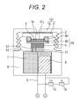
- Fig. 2 is a schematic diagram illustrating a sectional structure of another embodiment of the galvanic cell type oxygen sensor of the present invention.
- a second oxygen permeable membrane (17a in Fig. 2 ) is arranged between a first holder lid 1 and a second holder lid 10.
- the other structure and configuration are the same as in Fig. 1 ; thus, any description thereabout is omitted.
- This embodiment makes it possible to prevent the second oxygen permeable membrane 17a from being peeled off unexpectedly from the outer wall of the oxygen sensor.
- the second oxygen permeable membrane 17a is broken through from the outside to be pierced.
- each of the second oxygen permeable membranes 17 and 17a it is preferred to locate each of the second oxygen permeable membranes 17 and 17a to close the space.
- This manner makes it possible to seal up the oxygen sensor by use of only the second oxygen permeable membrane without requiring the whole of the oxygen sensor to be sealed up and wrapped with an oxygen gas barrier transparent film or any other. Thus, costs can be decreased.
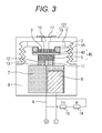
- the wording "close the space” referred to herein denotes the following: as illustrated in Fig. 3 , the second oxygen permeable membrane 17 is made depressed toward the space.
- the second oxygen permeable membrane 17 onto the outer wall of the oxygen sensor to close the space.
- This manner makes it possible to detach the second oxygen permeable membrane easily from the wall, and then use the sensor in an ordinary manner.
- the present embodiment can be applied to various oxygen sensors from any small-sized oxygen sensor (the volume of the space is 10 mm 3 or less, the space being made when the second oxygen permeable membrane 17 is attached to the outer wall of the oxygen sensor as illustrated in Fig. 1 ) to any large-sized oxygen sensor (the volume of the space is 200 mm 3 or more, the space being made when the second oxygen permeable membrane 17 is attached to the outer wall of the oxygen sensor as illustrated in Fig. 1 ).
- any small-sized oxygen sensor the volume of the space is 10 mm 3 or less, the space being made when the second oxygen permeable membrane 17 is attached to the outer wall of the oxygen sensor as illustrated in Fig. 1
- any large-sized oxygen sensor the volume of the space is 200 mm 3 or more, the space being made when the second oxygen permeable membrane 17 is attached to the outer wall of the oxygen sensor as illustrated in Fig. 1 ).
- the oxygen concentration in the space is lowered by effect of a balance between the consumption rate of oxygen that has permeated the first oxygen permeable membrane 4A and reduced on the positive electrode, and the oxygen permeation amount of the second oxygen permeable membrane into the space. Accordingly, as the volume of the space is smaller, the sensor can more rapidly and stably attain a state before the ordinary use.
- the present invention is not limited to the present embodiment, and thus the invention may be made into various embodiments as far as the embodiments do not depart from the technical scope of the present invention.
- the structure according to the members represented by reference numbers 1 to 15, respectively, in Fig. 1 is not limited to that illustrated in Fig. 1 .
- the structure may be changed in design as far as the structure gives a function as an oxygen sensor and further has an oxygen supplying path.
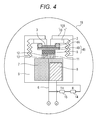
- Fig. 4 is a schematic diagram illustrating a sectional structure of still another embodiment of the galvanic cell type oxygen sensor of the present invention.
- the present invention may be a galvanic cell type oxygen sensor which is sealed up and wrapped with an oxygen gas barrier film 18 as described in JP-A-07-190984 without using the second oxygen permeable membrane 17 nor 17a, and which attains the adjustment of the amount of a deoxidizer in this film 18 to control the concentration of oxygen detected before ordinary use of the sensor into the range of 0.1 to 4.0% by volume both inclusive, or control the output voltage of the sensor before ordinary use of the sensor into the range of 2.5 to 20% both inclusive of the output voltage at the time of the ordinary use.
- Fig. 5 is a schematic diagram illustrating a sectional structure of an additional embodiment of the galvanic cell type oxygen sensor of the invention.
- the present invention may be a galvanic cell type oxygen sensor held in an oxygen-impermeable container 19 (made of, for example, a plastic or metallic material) without using the second oxygen permeable membrane 17 nor 17a in which oxygen gas is adjusted to control the concentration of oxygen detected before ordinary use of the sensor into the range of 0.1 to 4.0% by volume both inclusive, or to control the output voltage of the sensor before ordinary use of the sensor into the range of 2.5 to 20% both inclusive of the output voltage at the time of the ordinary use.
- an oxygen-impermeable container 19 made of, for example, a plastic or metallic material
- oxygen gas is adjusted to control the concentration of oxygen detected before ordinary use of the sensor into the range of 0.1 to 4.0% by volume both inclusive, or to control the output voltage of the sensor before ordinary use of the sensor into the range of 2.5 to 20% both inclusive of the output voltage at the time of the ordinary use.
- the above-mentioned oxygen concentration or output voltage can be evaluated by opening, in water, the inside of each of the oxygen gas barrier films 18 or the airtight container 19, keeping gas inside the film or the container 19 not to be mixed with the atmosphere, and then using another oxygen sensor to measure this kept gas thereabout.
- the present invention also provides a method for storing a galvanic cell type oxygen sensor including a positive electrode, a negative electrode, an electrolyte solution, and a first oxygen permeable membrane.
- the method is a method for storing such a galvanic cell type oxygen sensor, in which the concentration of oxygen detected before ordinary use of the sensor is controlled into the range of 0.1 to 4.0% by volume both inclusive, or in which the output voltage of the sensor before ordinary use of the sensor is controlled into the range of 2.5 to 20% both inclusive of the output voltage thereof at the time of the ordinary use.
- the same galvanic cell type oxygen sensor as illustrated in Fig. 1 was produced except that the second oxygen permeable membrane 17 was not located, this sensor having a one-year lifespan.
- the inner lid 1 was made of ABS resin;
- the protective membrane 3 was a porous sheet made of tetrafluoroethylene resin;
- the first oxygen permeable membrane 4A was a tetrafluoroethylene/hexafluoropropylene copolymer membrane;
- the catalyst electrode 4B was made of gold;
- the positive current collector 5 was made of titanium;
- the positive leading wire 6 was made of titanium; and the positive current collector 5 and the positive leading wire 6 were welded to each other to be integrated with each other.
- the electrolyte solution 7 was a mixed solution of acetic acid, potassium acetate and lead acetate in water; the negative electrode 8 was made of lead; the holder body 9 was made of ABS resin; the outer lid 10 was made of ABS resin; and the holder body 9 and the outer lid 9 were each screwed.
- the holder body 9 and the outer lid 10 were screwed onto each other to push/press the following onto each other: the inner lid 1, the O-ring 2, the tetrafluoroethylene resin sheet (protective membrane) 3, the tetrafluoroethylene/hexafluoropropylene copolymer membrane (first oxygen permeable membrane) 4A, the catalyst electrode 4B, and the positive current collector 5. In this way, these members were kept into a good contact state.
- the inner lid 1 functioned as a pushing/pressing end plate, and the O-ring 2 caused the sensor to be kept air-tight and liquid-tight.
- the bore 11 was a bore through which the electrolyte solution was supplied to the positive electrode and the first oxygen permeable membrane, and the bore 12 was a bore into which the titanium leading wire of the positive current collector was inserted.
- second oxygen permeable membranes were prepared for causing the oxygen concentration detected before ordinary use of these sensors to be adjusted into 0.05%, 0.1%, 2%, 4%, 10% and 21% by volume (21% by volume: the oxygen concentration in a state where no second oxygen permeable membrane is adhered), respectively, in the atmosphere at 25°C and 60% R.H. under 1013 hPa.
- These membranes were bonded to respective outer walls of the oxygen sensors to close their through hole (space) 16.
- the oxygen sensors illustrated in Fig. 1 were produced (their second oxygen permeable membrane 17 was made of polyethylene, and the oxygen concentration was adjusted in accordance with the thickness of the membrane).
- the volume of the space 16 was 2.4 mm 3 when the membrane was bonded to their outer wall, as illustrated in Fig. 1 .
- the oxygen sensors produced as described above were allowed to stand still at room temperature (25 ⁇ 5°C) for 90 days. After the 90 days, their second oxygen permeable membrane 17 was taken away. The respective theoretical lifespan deteriorations of the sensors were analyzed from comparison with the original sensor just after the production.
- Table 1 shows the results. [Table 1] Oxygen concentration before ordinary use Sensor property after 90 days Sensor lifespan deterioration Comparative Example 1 0.05 vol.% Abnormal sensor output recognized - Example 1 0.10 vol.% Not recognized 0% Example 2 2 vol.% Not recognized -2% Example 3 4 vol.% Not recognized -5% Comparative Example 2 10 vol.% Not recognized -12% Comparative Example 3 21 vol.% Not recognized -25%
- the same galvanic cell type oxygen sensor as illustrated in Fig. 1 was produced except that the second oxygen permeable membrane 17 was not located, this sensor having a one-year lifespan, in the same way as in Test 1 except that when the second oxygen permeable membrane 17 was to be attached to the outer wall of the oxygen sensor, the volume of the resultant space would be 10 mm 3 .
- second oxygen permeable membranes were prepared for causing the oxygen concentration detected before ordinary use of these sensors to be adjusted into 0.05%, 0.1%, 2%, 4%, 10% and 21% by volume (21% by volume: the oxygen concentration in a state where no second oxygen permeable membrane is adhered), respectively, in the atmosphere at 25°C and 60% R.H. under 1013 hPa.
- These membranes were bonded to respective outer walls of the oxygen sensors to close their through hole (space) 16.
- the oxygen sensors illustrated in Fig. 1 were produced (their second oxygen permeable membrane was made of polyethylene, and the oxygen concentration was adjusted in accordance with the thickness of the membrane).
- the oxygen sensors produced as described above were each allowed to stand still at room temperature (25 ⁇ 5°C) for 90 days. After the 90 days, their second oxygen permeable membrane 17 was taken away. The respective theoretical lifespan deteriorations of the sensors were analyzed from comparison with the original sensor just after the production.
- Table 2 shows the results. [Table 2] Oxygen concentration before ordinary use Sensor property after 90 days Sensor lifespan deterioration Comparative Example 4 0.05 vol.% Abnormal sensor output recognized - Example 4 0.10 vol.% Not recognized 0% Example 5 2 vol.% Not recognized -2% Example 6 4 vol.% Not recognized -5% Comparative Example 5 10 vol.% Not recognized -12% Comparative Example 6 21 vol.% Not recognized -25%
- the same galvanic cell type oxygen sensor as illustrated in Fig. 1 was produced except that the second oxygen permeable membrane 17 was not located, this sensor having a one-year lifespan.
- the inner lid 1 was made of ABS resin;
- the protective membrane 3 was a porous sheet made of tetrafluoroethylene resin;
- the first oxygen permeable membrane 4A was a tetrafluoroethylene/hexafluoropropylene copolymer membrane;
- the catalyst electrode 4B was made of gold;
- the positive current collector 5 was made of titanium;
- the positive leading wire 6 was made of titanium; and the positive current collector 5 and the positive leading wire 6 were welded to each other to be integrated with each other.
- the electrolyte solution 7 was a mixed solution of acetic acid, potassium acetate and lead acetate in water; the negative electrode 8 was made of lead; the holder body 9 was made of ABS resin; the outer lid 10 was made of ABS resin; and the holder body 9 and the outer lid 9 were each screwed.
- the holder body 9 and the outer lid 10 were screwed onto each other to push/press the following onto each other: the inner lid 1, the O-ring 2, the tetrafluoroethylene resin sheet (protective membrane) 3, the tetrafluoroethylene/hexafluoropropylene copolymer membrane (first oxygen permeable membrane) 4A, the catalyst electrode 4B, and the positive current collector 5. In this way, these members were kept into a good contact state.
- the inner lid 1 functioned as a pushing/pressing end plate, and the O-ring 2 caused the sensor to be kept air-tight and liquid-tight.
- the bore 11 was a bore through which the electrolyte solution was supplied to the positive electrode and the first oxygen permeable membrane, and the bore 12 was a bore into which the titanium leading wire of the positive current collector was inserted.
- a non- second -oxygen-permeable-membrane 17-bonded oxygen sensor in which B/A x 100 was 100%, was also produced.
- the volume of their space was 2.4 mm 3 when their second oxygen permeable membrane 17 was bonded to their outer wall, as illustrated in Fig. 1 .
- the output voltage measurement was made in the atmosphere at 25°C and 60% R.H. under 1013 hPa.
- the oxygen sensors produced as described above were each allowed to stand still at room temperature (25 ⁇ 5°C) for 180 days while the output voltage value was measured. After the 180 days, their second oxygen permeable membrane 17 was taken away. Sensor properties (such as the output voltage property) thereof were evaluated.
- the sensors were further allowed to stand still while the output voltage value was measured.
- the sensors were each analyzed about the use period until the output voltage was lowered to less than 80% of the output voltage at time of first ordinary use (hereinafter, the use period will be referred to as the sensor lifespan).
- the resultant respective sensor lifespans were compared with each other under a condition that the sensor lifespan obtained when the output proportion (B/A x 100) was 1% was regarded as 100.
- the respective second oxygen permeable membranes 17 plural second oxygen permeable membranes each made of polyethylene were used, these membranes 17 being various in film thickness for causing the proportion of the output voltage value (B) outputted before ordinary use (in the atmosphere having an oxygen concentration of 21%) of the produced sensors to the output voltage value (A) outputted at the time of the ordinary use (B/A x 100) to be adjusted into 1%, 2.5%, 5%, 10%, 20% and 40%, respectively.
- These membranes were bonded to respective outer walls of the oxygen sensors to be attachable thereto and detachable therefrom and close their through hole (space) 16. In this way, the oxygen sensors were produced.
- a non- second -oxygen-permeable-membrane 17-bonded oxygen sensor in which B/A x 100 was 100%, was also produced.
- the output voltage measurement was made in the atmosphere at 25°C and 60% R.H. under 1013 hPa.
- the oxygen sensors produced as described above were each allowed to stand still at room temperature (25 ⁇ 5°C) for 180 days while the output voltage value was measured. After the 180 days, the second oxygen permeable membrane 17 was taken away. Sensor properties (such as the output voltage property) thereof were evaluated.
- the sensors were further allowed to stand still while the output voltage value was measured.
- the sensors were each analyzed about the use period until the output voltage was lowered to less than 80% of the output voltage at time of first ordinary use (hereinafter, the use period will be referred to as the sensor lifespan).
- the respective sensor lifespans of these sensors were compared with each other under a condition that the sensor lifespan obtained when the output proportion (B/A x 100) was 1% was regarded as 100.
- Table 4 shows the results. [Table 4] Output proportion (B/A x 100) Sensor property after 180 days Sensor lifespan Comparative Example 4 1% Abnormal sensor output recognized - Example 5 2.5% Not recognized 100 Example 6 5% Not recognized 98 Example 7 10% Not recognized 95 Example 8 20% Not recognized 89 Comparative Example 5 40% Not recognized 75 Comparative Example 6 100% Not recognized 35
Landscapes
- Chemical & Material Sciences (AREA)
- Life Sciences & Earth Sciences (AREA)
- Health & Medical Sciences (AREA)
- Physics & Mathematics (AREA)
- Chemical Kinetics & Catalysis (AREA)
- Electrochemistry (AREA)
- Molecular Biology (AREA)
- Analytical Chemistry (AREA)
- Biochemistry (AREA)
- General Health & Medical Sciences (AREA)
- General Physics & Mathematics (AREA)
- Immunology (AREA)
- Pathology (AREA)
- Separation Using Semi-Permeable Membranes (AREA)
Abstract
Description
- The present invention relates to a galvanic cell type oxygen sensor including a positive electrode, a negative electrode, an electrolyte solution, and an oxygen permeable membrane.
- A galvanic cell type oxygen sensor including a positive electrode, a negative electrode, an electrolyte solution, and an oxygen permeable membrane is small and light, and is further operable at normal temperature and inexpensive. Thus, the sensor is used in various fields for the check of the state of oxygen deficiency in ship's holds and manholes, the detection of the concentration of oxygen in a medical instrument such as an anesthesia machine or an artificial respirator, and other purposes.
-
Fig. 6 illustrates an ordinary sectional structure of a galvanic cell type oxygen sensor that has been hitherto put into various practical uses. InFig. 6 ,reference number 1 represents a first holder lid (inner lid); 2, an O-ring; 3, a protective membrane for preventing the adhesion of rubbish and dust onto a first oxygen permeable membrane, and the adhesion of a water membrane thereto; 4A, the first oxygen permeable membrane; 4B, a catalyst electrode; 5, a positive current collector; 6, a positive leading wire; 7, an electrolyte solution; 8, a negative electrode; 9, a holder body; 10, a second holder lid (outer lid); 11, a bore through which the electrolyte solution is to be supplied; 12, a bore into which the leading wire is inserted; 13, a positive current collector holding region; 14, a correcting resistance; and 15, a temperature compensating thermistor. Thecatalyst electrode 4B and the positivecurrent collector 5 constitute apositive electrode 45. Thefirst holder lid 1 and thesecond holder lid 10 constitute aholder lid 101. - The principle of the operation of the galvanic cell type oxygen sensor is as follows: Oxygen that has passed through the first oxygen
permeable membrane 4A, through which oxygen is selectively caused to permeate, the amount of the permeation of oxygen being restricted in accordance with the reaction of the cell, is reduced in thecatalyst electrode 4B, which is capable of reducing oxygen electrochemically, so that electrochemical reactions described below are caused between thecatalyst electrode 4B and thenegative electrode 8 by aid of theelectrolyte solution 7. - When the electrolyte solution is acidic, the following are caused:
- Positive electrode reaction: O2 + 4H+ + 4e- → 2H2O
- Negative electrode reaction: 2Pb + 2H2O → 2PbO + 4H+ + 4e-
- Total reaction: 2Pb + O2 → 2PbO
- When the electrolyte solution is alkaline, the following are caused:
- Positive electrode reaction: O2 + 2H2O + 4e- → 4OH-
- Negative electrode reaction: 2Pb + 4OH- → 2PbO + 2H2O + 4e-
- Total reaction: 2Pb + O2 → 2PbO
- The case of the acidic electrolyte solution and that of the alkaline electrolyte solution are different from each other in electric charge carrier. However, in either one of these cases, a current corresponding to the concentration of oxygen is generated between the
catalyst electrode 4B and thenegative electrode 8. The current generated by the positive electrode reaction on thecatalyst electrode 4B is collected into the positivecurrent collector 5, which is brought into compressive contact with thecatalyst electrode 4B, and then led through the positive leadingwire 6 to the outside. The current flows through thecorrecting resistance 14 and thetemperature compensating thermistor 15 into the negative electrode to be converted into a voltage signal. As a result, a voltage is gained as an oxygen sensor output. Thereafter, the resultant output voltage is converted to the concentration of oxygen in a well-known manner, and then the oxygen concentration is detected. - When such a conventional galvanic cell type oxygen sensor is allowed to stand still in the atmosphere or any other oxygen-containing atmosphere, the above-mentioned electrochemical reaction is naturally generated so that the electrode material is unfavorably consumed. Thus, there remains a problem that when the storage period of the oxygen sensor is long before the use thereof, the use lifespan of the oxygen sensor is largely shortened.
- Thereagainst,
JP-A-07-190984 - According to the technique described in
JP-A-07-190984 - An object of the present invention is to provide a galvanic cell type oxygen sensor capable of restraining a different reaction as described above on its positive electrode while the electrode material thereof is restrained from being consumed.
- A first aspect of the galvanic cell type oxygen sensor according to the present invention is a sensor including a positive electrode, a negative electrode, an electrolyte solution, and a first oxygen permeable membrane, wherein the concentration of oxygen detected before ordinary use of the sensor is controlled into the range between 0.1% by volume or more and 4.0% by volume or less.
-
-
Fig. 1 is a schematic diagram illustrating a sectional structure of an embodiment of the galvanic cell type oxygen sensor of the present invention; -
Fig. 2 is a schematic diagram illustrating a sectional structure of another embodiment of the galvanic cell type oxygen sensor of the invention; -
Fig. 3 is a schematic diagram illustrating a sectional structure of the embodiment of the galvanic cell type oxygen sensor of the invention, the diagram being referred to for describing the wording "to close the space"; -
Fig. 4 is a schematic diagram illustrating a sectional structure of still another embodiment of the galvanic cell type oxygen sensor of the invention; -
Fig. 5 is a schematic diagram illustrating a sectional structure of an additional embodiment of the galvanic cell type oxygen sensor of the invention; and -
Fig. 6 is a schematic diagram illustrating an ordinary sectional structure of a conventional galvanic cell type oxygen sensor. - A first aspect of the galvanic cell type oxygen sensor according to the present invention is a sensor including a positive electrode, a negative electrode, an electrolyte solution, and a first oxygen permeable membrane, wherein the concentration of oxygen detected before ordinary use of the sensor is controlled into the range between 0.1% by volume or more and 4.0% by volume or less.
- The control is preferably made through a second oxygen permeable membrane that is arranged oppositely to the first oxygen permeable membrane to interpose a space therebetween, and that restricts the permeation amount of oxygen into the space.
- The second oxygen permeable membrane is preferably arranged to close the space.
- The space preferably has a volume of 10 mm3 or less.
- A second aspect of the galvanic cell type oxygen sensor according to the present invention is a sensor including a positive electrode, a negative electrode, an electrolyte solution, and a first oxygen permeable membrane, wherein the output voltage of the sensor before ordinary use of the sensor is controlled into the range between 2.5% or more and 20% or less of the output voltage thereof at the time of the ordinary use.
- The control is preferably made through a second oxygen permeable membrane that is arranged oppositely to the first oxygen permeable membrane to interpose a space therebetween, and that restricts the permeation amount of oxygen into the space.
- The second oxygen permeable membrane is preferably arranged to close the space.
- The space preferably has a volume of 10 mm3 or less.
- According to the aspects of the present invention, a galvanic cell type oxygen sensor is provided which makes it possible to restrain a different reaction on its positive electrode while the electrode material is restrained from being consumed.
- The galvanic cell type oxygen sensor according to the first aspect of the present invention is a galvanic cell type oxygen sensor including a positive electrode, a negative electrode, an electrolyte solution, and a first oxygen permeable membrane, wherein the concentration of oxygen detected before ordinary use of the sensor is controlled into the range of 0.1 to 4.0% by volume both inclusive.
- Such a wording "before ordinary use of the sensor" as referred to herein denotes a term when this produced oxygen sensor is not used for an original purpose thereof before or after the sensor is used in the atmosphere (oxygen concentration therein: about 21% by volume) in an ordinary manner.
- The galvanic cell type oxygen sensor according to the second aspect of the present invention is a galvanic cell type oxygen sensor including a positive electrode, a negative electrode, an electrolyte solution, and a first oxygen permeable membrane, wherein the output voltage of the sensor before ordinary use of the sensor is controlled into the range of 2.5 to 20% both inclusive of the output voltage thereof at the time of the ordinary use.
- Such a wording "the time of the ordinary use" as referred to herein denotes the time when the oxygen sensor is used in the atmosphere (oxygen concentration therein: about 21% by volume) in an ordinary manner, which will be detailed later. Such a wording "before ordinary use of the sensor" as referred to herein denotes a term before this produced sensor is used in the atmosphere (oxygen concentration therein: about 21% by volume) in an ordinary manner.
- The wording "the output voltage of the sensor before ordinary use of the sensor is controlled into the range of 2.5 to 20% both inclusive of the output voltage thereof at the time of the ordinary use" denotes that the proportion of the output voltage value (B) outputted before the ordinary use of the sensor to the output voltage value (A) outputted in the atmosphere (oxygen concentration therein: about 21% by volume) at the time of the ordinary use (B/A x 100, which will be referred to as the "output proportion" hereinafter) is from 2.5 to 20% both inclusive.
- In order to restrain the consumption of the material of electrodes of any galvanic cell type oxygen sensor before ordinary use of the sensor, it is generally preferred to store the oxygen sensor in a very highly oxygen-free state (in a state that the detected concentration of oxygen is a value very close to zero (the value will be referred to as "substantially zero" hereinafter)). However, at the time of ordinary use of the sensor after the oxygen sensor is stored in the state described above, the oxygen sensor may be in an abnormal output state. This problem has been found by the inventor.
- About this problem, it appears to the inventor that: when the volume of oxygen supplied to the positive electrode is very small, the above-mentioned positive electrode reaction is stopped so that the positive electrode potential becomes close to the negative electrode potential; thus, on the positive electrode, a reaction different from each of the above-mentioned positive electrode reactions is generated, and a product produced by this different reaction causes the oxygen sensor to generate an abnormal output at the time of ordinary use of the sensor.
- Thus, the inventor has supplied a very small volume of oxygen to an oxygen sensor without adjusting the oxygen concentration detected before ordinary use of the sensor to substantially zero, thereby not stopping the positive electrode reaction. The inventor has found out that this manner makes it possible to restrain the different reaction on the positive electrode.
- Specifically, the inventor has found out that in the first aspect of the present invention, the oxygen concentration detected before ordinary use of the present sensor is controlled to 0.1% by volume or more without adjusting this oxygen concentration to substantially zero, whereby the above-mentioned problem can be solved.
- However, if the oxygen concentration detected before the ordinary use is too high, the electrode material comes to be highly consumed. Thus, the upper limit thereof is preferably 4.0% by volume or less, more preferably 2.0% by volume or less.
- Furthermore, the inventor has found out that in the second aspect of the present invention, the output voltage before ordinary use of the present sensor is controlled to 2.5% or more of that at the time of the ordinary use without adjusting the output voltage before the ordinary use to substantially zero, whereby the above-mentioned problem can be solved.
- However, if the output voltage detected before the ordinary use is too high, the electrode material comes to be highly consumed. Thus, the upper limit thereof is preferably 20% or less, more preferably 10% or less, even more preferably 5% or less.
-
Fig. 1 is a schematic diagram illustrating a sectional structure of an embodiment of the galvanic cell type oxygen sensor of the present invention. InFig. 1 ,reference numbers 1 to 15, 45 and 101 are the same as inFig. 6 . - As illustrated in
Fig. 1 , a galvanic cell type oxygen sensor according to the present embodiment has aholder body 9; apositive electrode 45, anegative electrode 8 and anelectrolyte solution 7 each located or charged in theholder body 9; a first oxygenpermeable membrane 4A located to contact thepositive electrode 45; aprotective membrane 3 located on the first oxygenpermeable membrane 4A to contact the first oxygenpermeable membrane 4A; aholder lid 101 bonded onto theholder body 9, or set onto theholder body 9 to be attachable onto or detachable from theholder body 9, a throughhole 16 being made in theholder lid 101 and being an oxygen supplying path (i.e., a space) connected to the first oxygenpermeable membrane 4A; a correctingresistance 14 and atemperature compensating thermistor 15 connected in series to thepositive electrode 45 and thenegative electrode 8; and a second oxygenpermeable membrane 17 arranged oppositely to the first oxygenpermeable membrane 4A to interpose the space (the through hole 16) therebetween. - As illustrated in
Fig. 1 , in the present embodiment, the second oxygenpermeable membrane 17 is bonded to an outer wall of the oxygen sensor. - As described above, the first oxygen
permeable membrane 4A is a member through which oxygen is selectively caused to permeate, the amount of the permeation of oxygen being restricted by this first oxygenpermeable membrane 4A in accordance with the reaction of the cell. The material, the thickness and other factors of the first oxygenpermeable membrane 4A are appropriately decided. The first oxygenpermeable membrane 4A may be a porous membrane, a non-porous membrane, or a capillary resin membrane. In the embodiment according to the first aspect, as to the second oxygenpermeable membrane 17, the concentration of oxygen detected before ordinary use of the sensor is controlled into the range of 0.1 to 4.0% by volume both inclusive. This control of the oxygen concentration can be suitably attained through the material or the thickness of the second oxygenpermeable membrane 17, or the area of the second oxygenpermeable membrane 17 that comes into contact with gas. In the embodiment according to the second aspect, as to the second oxygenpermeable membrane 17, the output voltage of the sensor before ordinary use thereof is controlled into the range of 2.5 to 20% both inclusive of the output voltage at the time of the ordinary use. This control of the output voltage can be suitably attained through the material or the thickness of the second oxygenpermeable membrane 17, or the area of the second oxygenpermeable membrane 17 that comes into contact with gas. - The material of the second oxygen
permeable membrane 17 may be a material low in oxygen permeability, such as polyethylene terephthalate (PET), polyamide, drawn polypropylene, cellophane, or polyvinyl alcohol, or a material high in oxygen permeability, such as polyethylene, non-drawn polypropylene, polymethylpentene, cyclic polyolefin, olefin-based thermoplastic elastomer, styrene-based thermoplastic elastomer, or polyamide-based thermoplastic elastomer. The oxygen concentration detected before the ordinary use is controlled by making use of one or more of these materials and optionally making an appropriate adjustment of the thickness of the membrane. -
Fig. 2 is a schematic diagram illustrating a sectional structure of another embodiment of the galvanic cell type oxygen sensor of the present invention. - In the present embodiment, a second oxygen permeable membrane (17a in
Fig. 2 ) is arranged between afirst holder lid 1 and asecond holder lid 10. The other structure and configuration are the same as inFig. 1 ; thus, any description thereabout is omitted. - This embodiment makes it possible to prevent the second oxygen permeable membrane 17a from being peeled off unexpectedly from the outer wall of the oxygen sensor.
- In order to use the galvanic cell type oxygen sensor of the present embodiment in an ordinary manner, the second oxygen permeable membrane 17a is broken through from the outside to be pierced.
- It is preferred to locate each of the second oxygen
permeable membranes 17 and 17a to close the space. - This manner makes it possible to seal up the oxygen sensor by use of only the second oxygen permeable membrane without requiring the whole of the oxygen sensor to be sealed up and wrapped with an oxygen gas barrier transparent film or any other. Thus, costs can be decreased.
- When the case illustrated in
Fig. 1 is given as an example, the wording "close the space" referred to herein denotes the following: as illustrated inFig. 3 , the second oxygenpermeable membrane 17 is made depressed toward the space. - As illustrated in
Fig. 1 , it is preferred to attach the second oxygenpermeable membrane 17 onto the outer wall of the oxygen sensor to close the space. - This manner makes it possible to detach the second oxygen permeable membrane easily from the wall, and then use the sensor in an ordinary manner.
- The present embodiment can be applied to various oxygen sensors from any small-sized oxygen sensor (the volume of the space is 10 mm3 or less, the space being made when the second oxygen
permeable membrane 17 is attached to the outer wall of the oxygen sensor as illustrated inFig. 1 ) to any large-sized oxygen sensor (the volume of the space is 200 mm3 or more, the space being made when the second oxygenpermeable membrane 17 is attached to the outer wall of the oxygen sensor as illustrated inFig. 1 ). - As illustrated in
Fig. 1 , in the present embodiment, before the ordinary use, the oxygen concentration in the space is lowered by effect of a balance between the consumption rate of oxygen that has permeated the first oxygenpermeable membrane 4A and reduced on the positive electrode, and the oxygen permeation amount of the second oxygen permeable membrane into the space. Accordingly, as the volume of the space is smaller, the sensor can more rapidly and stably attain a state before the ordinary use. - It is therefore preferred to apply the present embodiment to a small-sized oxygen sensor, which turns easily into such a state, since a larger advantageous effect can be obtained.
- The present invention is not limited to the present embodiment, and thus the invention may be made into various embodiments as far as the embodiments do not depart from the technical scope of the present invention. For example, the structure according to the members represented by
reference numbers 1 to 15, respectively, inFig. 1 is not limited to that illustrated inFig. 1 . Thus, the structure may be changed in design as far as the structure gives a function as an oxygen sensor and further has an oxygen supplying path. -
Fig. 4 is a schematic diagram illustrating a sectional structure of still another embodiment of the galvanic cell type oxygen sensor of the present invention. - As illustrated in
Fig. 4 , the present invention may be a galvanic cell type oxygen sensor which is sealed up and wrapped with an oxygengas barrier film 18 as described inJP-A-07-190984 permeable membrane 17 nor 17a, and which attains the adjustment of the amount of a deoxidizer in thisfilm 18 to control the concentration of oxygen detected before ordinary use of the sensor into the range of 0.1 to 4.0% by volume both inclusive, or control the output voltage of the sensor before ordinary use of the sensor into the range of 2.5 to 20% both inclusive of the output voltage at the time of the ordinary use. -
Fig. 5 is a schematic diagram illustrating a sectional structure of an additional embodiment of the galvanic cell type oxygen sensor of the invention. - As illustrated in
Fig. 5 , the present invention may be a galvanic cell type oxygen sensor held in an oxygen-impermeable container 19 (made of, for example, a plastic or metallic material) without using the second oxygenpermeable membrane 17 nor 17a in which oxygen gas is adjusted to control the concentration of oxygen detected before ordinary use of the sensor into the range of 0.1 to 4.0% by volume both inclusive, or to control the output voltage of the sensor before ordinary use of the sensor into the range of 2.5 to 20% both inclusive of the output voltage at the time of the ordinary use. - The above-mentioned oxygen concentration or output voltage can be evaluated by opening, in water, the inside of each of the oxygen
gas barrier films 18 or theairtight container 19, keeping gas inside the film or thecontainer 19 not to be mixed with the atmosphere, and then using another oxygen sensor to measure this kept gas thereabout. - The present invention also provides a method for storing a galvanic cell type oxygen sensor including a positive electrode, a negative electrode, an electrolyte solution, and a first oxygen permeable membrane.
- Specifically, the method is a method for storing such a galvanic cell type oxygen sensor, in which the concentration of oxygen detected before ordinary use of the sensor is controlled into the range of 0.1 to 4.0% by volume both inclusive, or in which the output voltage of the sensor before ordinary use of the sensor is controlled into the range of 2.5 to 20% both inclusive of the output voltage thereof at the time of the ordinary use.
- The use of this storing method makes it possible to produce the same advantageous effect as described above (the above-mentioned different reaction on the positive electrode is restrained while the consumption of the electrode material is restrained).
- The following will more specifically describe the present invention by way of working examples thereof. However, the invention is not limited to these examples.
- The same galvanic cell type oxygen sensor as illustrated in
Fig. 1 was produced except that the second oxygenpermeable membrane 17 was not located, this sensor having a one-year lifespan. InFig. 1 , theinner lid 1 was made of ABS resin; theprotective membrane 3 was a porous sheet made of tetrafluoroethylene resin; the first oxygenpermeable membrane 4A was a tetrafluoroethylene/hexafluoropropylene copolymer membrane; thecatalyst electrode 4B was made of gold; the positivecurrent collector 5 was made of titanium; the positiveleading wire 6 was made of titanium; and the positivecurrent collector 5 and the positiveleading wire 6 were welded to each other to be integrated with each other. - The
electrolyte solution 7 was a mixed solution of acetic acid, potassium acetate and lead acetate in water; thenegative electrode 8 was made of lead; theholder body 9 was made of ABS resin; theouter lid 10 was made of ABS resin; and theholder body 9 and theouter lid 9 were each screwed. - The
holder body 9 and theouter lid 10 were screwed onto each other to push/press the following onto each other: theinner lid 1, the O-ring 2, the tetrafluoroethylene resin sheet (protective membrane) 3, the tetrafluoroethylene/hexafluoropropylene copolymer membrane (first oxygen permeable membrane) 4A, thecatalyst electrode 4B, and the positivecurrent collector 5. In this way, these members were kept into a good contact state. Theinner lid 1 functioned as a pushing/pressing end plate, and the O-ring 2 caused the sensor to be kept air-tight and liquid-tight. - As described above, the
bore 11 was a bore through which the electrolyte solution was supplied to the positive electrode and the first oxygen permeable membrane, and thebore 12 was a bore into which the titanium leading wire of the positive current collector was inserted. - Next, second oxygen permeable membranes were prepared for causing the oxygen concentration detected before ordinary use of these sensors to be adjusted into 0.05%, 0.1%, 2%, 4%, 10% and 21% by volume (21% by volume: the oxygen concentration in a state where no second oxygen permeable membrane is adhered), respectively, in the atmosphere at 25°C and 60% R.H. under 1013 hPa. These membranes were bonded to respective outer walls of the oxygen sensors to close their through hole (space) 16. In this way, the oxygen sensors illustrated in
Fig. 1 were produced (their second oxygenpermeable membrane 17 was made of polyethylene, and the oxygen concentration was adjusted in accordance with the thickness of the membrane). The volume of thespace 16 was 2.4 mm3 when the membrane was bonded to their outer wall, as illustrated inFig. 1 . - In this case, after a predetermined period elapsed, about all the oxygen sensors except the non- second-oxygen-permeable-membrane-bonded oxygen sensor (oxygen concentration: 21%), their second oxygen
permeable membrane 17 turned to a state of being made depressed toward their space, as illustrated inFig. 3 . - The oxygen sensors produced as described above were allowed to stand still at room temperature (25 ± 5°C) for 90 days. After the 90 days, their second oxygen
permeable membrane 17 was taken away. The respective theoretical lifespan deteriorations of the sensors were analyzed from comparison with the original sensor just after the production. - Table 1 shows the results.
[Table 1] Oxygen concentration before ordinary use Sensor property after 90 days Sensor lifespan deterioration Comparative Example 1 0.05 vol.% Abnormal sensor output recognized - Example 1 0.10 vol.% Not recognized 0% Example 2 2 vol.% Not recognized -2% Example 3 4 vol.% Not recognized -5% Comparative Example 2 10 vol.% Not recognized -12% Comparative Example 3 21 vol.% Not recognized -25% - As shown in Table 1, when the oxygen concentration before the ordinary use was less than 0.1% by volume (Comparative Example 1), it was verified that the sensor gave an abnormal output (output voltage abnormality).
- When the oxygen concentration before the ordinary use was 10% by volume or more (Comparative Examples 2 and 3), it was verified that the sensor lifespan thereof was largely shortened.
- The same galvanic cell type oxygen sensor as illustrated in
Fig. 1 was produced except that the second oxygenpermeable membrane 17 was not located, this sensor having a one-year lifespan, in the same way as inTest 1 except that when the second oxygenpermeable membrane 17 was to be attached to the outer wall of the oxygen sensor, the volume of the resultant space would be 10 mm3. - Next, second oxygen permeable membranes were prepared for causing the oxygen concentration detected before ordinary use of these sensors to be adjusted into 0.05%, 0.1%, 2%, 4%, 10% and 21% by volume (21% by volume: the oxygen concentration in a state where no second oxygen permeable membrane is adhered), respectively, in the atmosphere at 25°C and 60% R.H. under 1013 hPa. These membranes were bonded to respective outer walls of the oxygen sensors to close their through hole (space) 16. In this way, the oxygen sensors illustrated in
Fig. 1 were produced (their second oxygen permeable membrane was made of polyethylene, and the oxygen concentration was adjusted in accordance with the thickness of the membrane). - In this case, after a predetermined period elapsed, about all the oxygen sensors except the non- second-oxygen-permeable-membrane-bonded oxygen sensor, in which the oxygen concentration was 21% by volume, their second oxygen
permeable membrane 17 turned to a state of being made depressed toward their space, as illustrated inFig. 3 . - In the same way as in
Test 1, the oxygen sensors produced as described above were each allowed to stand still at room temperature (25 ± 5°C) for 90 days. After the 90 days, their second oxygenpermeable membrane 17 was taken away. The respective theoretical lifespan deteriorations of the sensors were analyzed from comparison with the original sensor just after the production. - Table 2 shows the results.
[Table 2] Oxygen concentration before ordinary use Sensor property after 90 days Sensor lifespan deterioration Comparative Example 4 0.05 vol.% Abnormal sensor output recognized - Example 4 0.10 vol.% Not recognized 0% Example 5 2 vol.% Not recognized -2% Example 6 4 vol.% Not recognized -5% Comparative Example 5 10 vol.% Not recognized -12% Comparative Example 6 21 vol.% Not recognized -25% - In
Test 2, as shown in Table 2, when the oxygen concentration before the ordinary use was less than 0.1% by volume (Comparative Example 4), it was verified in the same manner as inTest 1 that the sensor gave an abnormal output (output voltage abnormality). - When the oxygen concentration before the ordinary use was 10% by volume or more (Comparative Examples 5 and 6), the tendency was verified that the sensor lifespan was largely shortened.
- The same galvanic cell type oxygen sensor as illustrated in
Fig. 1 was produced except that the second oxygenpermeable membrane 17 was not located, this sensor having a one-year lifespan. InFig. 1 , theinner lid 1 was made of ABS resin; theprotective membrane 3 was a porous sheet made of tetrafluoroethylene resin; the first oxygenpermeable membrane 4A was a tetrafluoroethylene/hexafluoropropylene copolymer membrane; thecatalyst electrode 4B was made of gold; the positivecurrent collector 5 was made of titanium; the positiveleading wire 6 was made of titanium; and the positivecurrent collector 5 and the positiveleading wire 6 were welded to each other to be integrated with each other. - The
electrolyte solution 7 was a mixed solution of acetic acid, potassium acetate and lead acetate in water; thenegative electrode 8 was made of lead; theholder body 9 was made of ABS resin; theouter lid 10 was made of ABS resin; and theholder body 9 and theouter lid 9 were each screwed. - The
holder body 9 and theouter lid 10 were screwed onto each other to push/press the following onto each other: theinner lid 1, the O-ring 2, the tetrafluoroethylene resin sheet (protective membrane) 3, the tetrafluoroethylene/hexafluoropropylene copolymer membrane (first oxygen permeable membrane) 4A, thecatalyst electrode 4B, and the positivecurrent collector 5. In this way, these members were kept into a good contact state. Theinner lid 1 functioned as a pushing/pressing end plate, and the O-ring 2 caused the sensor to be kept air-tight and liquid-tight. - As described above, the
bore 11 was a bore through which the electrolyte solution was supplied to the positive electrode and the first oxygen permeable membrane, and thebore 12 was a bore into which the titanium leading wire of the positive current collector was inserted. - Next, plural second oxygen permeable membranes each made of polyethylene were used, these
membranes 17 being various in film thickness for causing the proportion of the output voltage value (B) outputted before ordinary use (in the atmosphere having an oxygen concentration of 21%) of the produced sensors to the output voltage value (A) outputted at the time of the ordinary use (B/A x 100) to be adjusted into 1%, 2.5%, 5%, 10%, 20% and 40%, respectively. These membranes were bonded to respective outer walls of the oxygen sensors to be attachable thereto and detachable therefrom and close their through hole (space) 16. In this way, the oxygen sensors were produced. Moreover, a non- second -oxygen-permeable-membrane 17-bonded oxygen sensor, in which B/A x 100 was 100%, was also produced. The volume of their space was 2.4 mm3 when their second oxygenpermeable membrane 17 was bonded to their outer wall, as illustrated inFig. 1 . The output voltage measurement was made in the atmosphere at 25°C and 60% R.H. under 1013 hPa. - In this case, after a predetermined period elapsed, about all the oxygen sensors except the non- second -oxygen-permeable-membrane-bonded oxygen sensor, in which B/A x 100 was 100%, their second oxygen
permeable membrane 17 turned to a state of being made depressed toward their space, as illustrated inFig. 3 . - The oxygen sensors produced as described above were each allowed to stand still at room temperature (25 ± 5°C) for 180 days while the output voltage value was measured. After the 180 days, their second oxygen
permeable membrane 17 was taken away. Sensor properties (such as the output voltage property) thereof were evaluated. - In the state that the second oxygen
permeable membrane 17 had been taken away, the sensors were further allowed to stand still while the output voltage value was measured. The sensors were each analyzed about the use period until the output voltage was lowered to less than 80% of the output voltage at time of first ordinary use (hereinafter, the use period will be referred to as the sensor lifespan). The resultant respective sensor lifespans were compared with each other under a condition that the sensor lifespan obtained when the output proportion (B/A x 100) was 1% was regarded as 100. - Table 3 shows the results.
[Table 3] Output proportion (B/A x 100) Sensor property after 180 days Sensor lifespan Comparative Example 1 1% Abnormal sensor output recognized - Example 1 2.5% Not recognized 100 Example 2 5% Not recognized 98 Example 3 10% Not recognized 95 Example 4 20% Not recognized 89 Comparative Example 2 40% Not recognized 75 Comparative Example 3 100% Not recognized 35 - As shown in Table 3, when the output proportion (B/A x 100) was less than 2.5%, it was verified that the sensor gave an abnormal output (output voltage abnormality). When the output proportion (B/A x 100) was more than 20%, it was verified that the sensor lifespan was largely shortened. Test 2:
- The same galvanic cell type oxygen sensor as illustrated in
Fig. 1 was produced except that the second oxygenpermeable membrane 17 was not located, this sensor having a one-year lifespan, in the same way as inTest 1 except that when the second oxygenpermeable membrane 17 was to be attached to the outer wall of the oxygen sensor, the volume of the resultant space would be 10 mm3. - Next, as the respective second oxygen
permeable membranes 17, plural second oxygen permeable membranes each made of polyethylene were used, thesemembranes 17 being various in film thickness for causing the proportion of the output voltage value (B) outputted before ordinary use (in the atmosphere having an oxygen concentration of 21%) of the produced sensors to the output voltage value (A) outputted at the time of the ordinary use (B/A x 100) to be adjusted into 1%, 2.5%, 5%, 10%, 20% and 40%, respectively. These membranes were bonded to respective outer walls of the oxygen sensors to be attachable thereto and detachable therefrom and close their through hole (space) 16. In this way, the oxygen sensors were produced. Moreover, a non- second -oxygen-permeable-membrane 17-bonded oxygen sensor, in which B/A x 100 was 100%, was also produced. The output voltage measurement was made in the atmosphere at 25°C and 60% R.H. under 1013 hPa. - In this case, after a predetermined period elapsed, about all the oxygen sensors except the non- second -oxygen-permeable-membrane 17-bonded oxygen sensor, in which B/A x 100 was 100%, their second oxygen
permeable membrane 17 turned to a state of being made depressed toward their space, as illustrated inFig. 3 . - In the same way as in
Test 1, the oxygen sensors produced as described above were each allowed to stand still at room temperature (25 ± 5°C) for 180 days while the output voltage value was measured. After the 180 days, the second oxygenpermeable membrane 17 was taken away. Sensor properties (such as the output voltage property) thereof were evaluated. - In the state that the second oxygen
permeable membrane 17 had been taken away, the sensors were further allowed to stand still while the output voltage value was measured. The sensors were each analyzed about the use period until the output voltage was lowered to less than 80% of the output voltage at time of first ordinary use (hereinafter, the use period will be referred to as the sensor lifespan). The respective sensor lifespans of these sensors were compared with each other under a condition that the sensor lifespan obtained when the output proportion (B/A x 100) was 1% was regarded as 100. - Table 4 shows the results.
[Table 4] Output proportion (B/A x 100) Sensor property after 180 days Sensor lifespan Comparative Example 4 1% Abnormal sensor output recognized - Example 5 2.5% Not recognized 100 Example 6 5% Not recognized 98 Example 7 10% Not recognized 95 Example 8 20% Not recognized 89 Comparative Example 5 40% Not recognized 75 Comparative Example 6 100% Not recognized 35 - In
Test 2, as shown in Table 4, when the output proportion (B/A x 100) was less than 2.5%, it was verified in the same manner as inTest 1 that the sensor gave an abnormal output (output voltage abnormality). When the output proportion (B/A x 100) was more than 20%, it was verified that the sensor lifespan was largely shortened.
Claims (8)
- A galvanic cell type oxygen sensor, comprising a positive electrode, a negative electrode, an electrolyte solution, and a first oxygen permeable membrane, wherein
the concentration of oxygen detected before ordinary use of the sensor is controlled into the range between 0.1% by volume or more and 4.0% by volume or less. - The galvanic cell type oxygen sensor according to claim 1, wherein the control is made through a second oxygen permeable membrane that is arranged oppositely to the first oxygen permeable membrane to interpose a space therebetween, and that restricts the permeation amount of oxygen into the space.
- The galvanic cell type oxygen sensor according to claim 2, wherein the second oxygen permeable membrane is arranged to close the space.
- The galvanic cell type oxygen sensor according to claim 2 or 3, wherein the space has a volume of 10 mm3 or less.
- A galvanic cell type oxygen sensor, comprising a positive electrode, a negative electrode, an electrolyte solution, and a first oxygen permeable membrane, wherein
the output voltage of the sensor before ordinary use of the sensor is controlled into the range between 2.5% or more and 20% or less of the output voltage thereof at the time of the ordinary use. - The galvanic cell type oxygen sensor according to claim 5, wherein the control is made through an oxygen permeable membrane that is arranged oppositely to the first oxygen permeable membrane to interpose a space therebetween, and that restricts the permeation amount of oxygen into the space.
- The galvanic cell type oxygen sensor according to claim 6, wherein the oxygen permeable membrane is arranged to close the space.
- The galvanic cell type oxygen sensor according to claim 6 or 7, wherein the space has a volume of 10 mm3 or less.
Priority Applications (1)
| Application Number | Priority Date | Filing Date | Title |
|---|---|---|---|
| EP15193610.1A EP3012625B1 (en) | 2013-07-12 | 2014-07-11 | Galvanic cell type oxygen sensor |
Applications Claiming Priority (4)
| Application Number | Priority Date | Filing Date | Title |
|---|---|---|---|
| JP2013147057 | 2013-07-12 | ||
| JP2013147085 | 2013-07-12 | ||
| JP2014139569A JP6213401B2 (en) | 2013-07-12 | 2014-07-07 | Galvanic cell oxygen sensor |
| JP2014139586A JP6183307B2 (en) | 2013-07-12 | 2014-07-07 | Galvanic cell oxygen sensor |
Related Child Applications (2)
| Application Number | Title | Priority Date | Filing Date |
|---|---|---|---|
| EP15193610.1A Division EP3012625B1 (en) | 2013-07-12 | 2014-07-11 | Galvanic cell type oxygen sensor |
| EP15193610.1A Division-Into EP3012625B1 (en) | 2013-07-12 | 2014-07-11 | Galvanic cell type oxygen sensor |
Publications (2)
| Publication Number | Publication Date |
|---|---|
| EP2824452A1 true EP2824452A1 (en) | 2015-01-14 |
| EP2824452B1 EP2824452B1 (en) | 2016-09-14 |
Family
ID=51162598
Family Applications (2)
| Application Number | Title | Priority Date | Filing Date |
|---|---|---|---|
| EP14176670.9A Active EP2824452B1 (en) | 2013-07-12 | 2014-07-11 | Galvanic cell type oxygen sensor |
| EP15193610.1A Active EP3012625B1 (en) | 2013-07-12 | 2014-07-11 | Galvanic cell type oxygen sensor |
Family Applications After (1)
| Application Number | Title | Priority Date | Filing Date |
|---|---|---|---|
| EP15193610.1A Active EP3012625B1 (en) | 2013-07-12 | 2014-07-11 | Galvanic cell type oxygen sensor |
Country Status (3)
| Country | Link |
|---|---|
| US (1) | US9599585B2 (en) |
| EP (2) | EP2824452B1 (en) |
| CN (1) | CN104280442B (en) |
Cited By (1)
| Publication number | Priority date | Publication date | Assignee | Title |
|---|---|---|---|---|
| DE102017216191A1 (en) | 2017-09-13 | 2019-03-14 | Robert Bosch Gmbh | Particle sensor with a ceramic sensor body produced by injection molding |
Families Citing this family (3)
| Publication number | Priority date | Publication date | Assignee | Title |
|---|---|---|---|---|
| CN104990970A (en) * | 2015-06-24 | 2015-10-21 | 中山欧麦克仪器设备有限公司 | A Dissolved Oxygen Sensor with Automatic Temperature Compensation |
| CN117929502A (en) * | 2018-10-17 | 2024-04-26 | 麦克赛尔株式会社 | Electrochemical oxygen sensor |
| US20220326174A1 (en) * | 2021-04-09 | 2022-10-13 | Maxell, Ltd. | Electrochemical oxygen sensor |
Citations (5)
| Publication number | Priority date | Publication date | Assignee | Title |
|---|---|---|---|---|
| EP0100463A1 (en) * | 1982-07-14 | 1984-02-15 | Radiometer A/S | Electrochemical measuring electrode device for simultaneously measuring the partial pressures of two gasses |
| US4695361A (en) * | 1985-11-04 | 1987-09-22 | Seatronics, Inc. | Oxygen sensor |
| JPH07190984A (en) | 1993-12-27 | 1995-07-28 | Toko Kagaku Kenkyusho:Kk | Oxygen gas sensor package |
| WO2004031758A1 (en) * | 2002-10-07 | 2004-04-15 | City Technology Limited | Electrochemical oxygen sensor |
| EP2219024A1 (en) * | 2007-11-28 | 2010-08-18 | GS Yuasa Corporation | Electrochemical oxygen sensor |
Family Cites Families (9)
| Publication number | Priority date | Publication date | Assignee | Title |
|---|---|---|---|---|
| GB1571282A (en) * | 1976-03-11 | 1980-07-09 | City Tech | Gas sensor |
| US4324632A (en) * | 1979-05-17 | 1982-04-13 | City Technology Limited | Gas sensor |
| GB8611397D0 (en) * | 1986-05-09 | 1986-06-18 | Neotronics Ltd | Gas sensor |
| GB8928177D0 (en) * | 1989-12-13 | 1990-02-14 | City Tech | Flammable gas detection |
| JP2599081B2 (en) * | 1992-09-30 | 1997-04-09 | 日本電池株式会社 | Galvanic cell type oxygen sensor |
| JP3815523B2 (en) * | 1997-04-17 | 2006-08-30 | 株式会社ジーエス・ユアサコーポレーション | Galvanic cell oxygen sensor |
| JP2005043303A (en) | 2003-07-25 | 2005-02-17 | Toyota Industries Corp | Moisture / gas detection method, moisture / gas sensor, moisture / gas detection device using the sensor, moisture / gas sensor, method for storing the moisture / gas detection device, and storage device |
| CN101498681B (en) * | 2009-03-13 | 2012-05-09 | 吴守清 | Electrode for measuring trace dissolved oxygen |
| CN202133638U (en) * | 2011-05-26 | 2012-02-01 | 北京大华融源技术有限公司 | Primary cell type dissolved oxygen sensor |
-
2014
- 2014-07-08 CN CN201410322901.2A patent/CN104280442B/en active Active
- 2014-07-11 EP EP14176670.9A patent/EP2824452B1/en active Active
- 2014-07-11 US US14/328,801 patent/US9599585B2/en active Active
- 2014-07-11 EP EP15193610.1A patent/EP3012625B1/en active Active
Patent Citations (5)
| Publication number | Priority date | Publication date | Assignee | Title |
|---|---|---|---|---|
| EP0100463A1 (en) * | 1982-07-14 | 1984-02-15 | Radiometer A/S | Electrochemical measuring electrode device for simultaneously measuring the partial pressures of two gasses |
| US4695361A (en) * | 1985-11-04 | 1987-09-22 | Seatronics, Inc. | Oxygen sensor |
| JPH07190984A (en) | 1993-12-27 | 1995-07-28 | Toko Kagaku Kenkyusho:Kk | Oxygen gas sensor package |
| WO2004031758A1 (en) * | 2002-10-07 | 2004-04-15 | City Technology Limited | Electrochemical oxygen sensor |
| EP2219024A1 (en) * | 2007-11-28 | 2010-08-18 | GS Yuasa Corporation | Electrochemical oxygen sensor |
Cited By (1)
| Publication number | Priority date | Publication date | Assignee | Title |
|---|---|---|---|---|
| DE102017216191A1 (en) | 2017-09-13 | 2019-03-14 | Robert Bosch Gmbh | Particle sensor with a ceramic sensor body produced by injection molding |
Also Published As
| Publication number | Publication date |
|---|---|
| US20150014166A1 (en) | 2015-01-15 |
| EP3012625B1 (en) | 2017-05-24 |
| CN104280442B (en) | 2018-04-27 |
| EP2824452B1 (en) | 2016-09-14 |
| EP3012625A1 (en) | 2016-04-27 |
| US9599585B2 (en) | 2017-03-21 |
| CN104280442A (en) | 2015-01-14 |
Similar Documents
| Publication | Publication Date | Title |
|---|---|---|
| EP2824452B1 (en) | Galvanic cell type oxygen sensor | |
| CN109642887B (en) | Electrochemical oxygen sensor | |
| JP6183307B2 (en) | Galvanic cell oxygen sensor | |
| JP6213401B2 (en) | Galvanic cell oxygen sensor | |
| CN2241341Y (en) | Acid electrolyte primary cell type dissolved oxygen sensor | |
| CN110749636B (en) | Diaphragm sensor, liquid analyzer, and liquid analyzing method | |
| JP4908229B2 (en) | Tab system for pneumatic electrochemical cells | |
| JP2015230172A (en) | Diaphragm sensor, liquid analyzer | |
| JP3815523B2 (en) | Galvanic cell oxygen sensor | |
| JP2002350384A (en) | Galvanic cell type oxygen sensor | |
| WO1996035944A1 (en) | Oxygen sensor | |
| JP2019066328A (en) | Electrochemical oxygen sensor | |
| CN107850563A (en) | Potentiostatic deposition formula gas sensor | |
| JP4540021B2 (en) | Galvanic cell oxygen sensor | |
| JPH11230933A (en) | Controlled potential electrolytic gas sensor | |
| JPH07190984A (en) | Oxygen gas sensor package | |
| JP2532334B2 (en) | Galvanic battery gas sensor | |
| JP2025107921A (en) | Gas Sensor Device | |
| JPH06109694A (en) | Galvanic battery oxygen sensor | |
| JP6473351B2 (en) | Constant potential electrolytic gas sensor | |
| JPS60260840A (en) | Galvanic cell type oxygen sensor | |
| JPS6140559A (en) | Galvanic battery type oxygen sensor | |
| JP2000039417A (en) | Diaphragm type electrochemical gas detector | |
| FR2225744A1 (en) | Measurement of small oxygen contents - in solids or liquids at ambient temperature especially for blood or effluent | |
| JPH06213861A (en) | Galvanic battery oxygen sensor |
Legal Events
| Date | Code | Title | Description |
|---|---|---|---|
| 17P | Request for examination filed |
Effective date: 20140711 |
|
| AK | Designated contracting states |
Kind code of ref document: A1 Designated state(s): AL AT BE BG CH CY CZ DE DK EE ES FI FR GB GR HR HU IE IS IT LI LT LU LV MC MK MT NL NO PL PT RO RS SE SI SK SM TR |
|
| AX | Request for extension of the european patent |
Extension state: BA ME |
|
| PUAI | Public reference made under article 153(3) epc to a published international application that has entered the european phase |
Free format text: ORIGINAL CODE: 0009012 |
|
| R17P | Request for examination filed (corrected) |
Effective date: 20150630 |
|
| RBV | Designated contracting states (corrected) |
Designated state(s): AL AT BE BG CH CY CZ DE DK EE ES FI FR GB GR HR HU IE IS IT LI LT LU LV MC MK MT NL NO PL PT RO RS SE SI SK SM TR |
|
| 17Q | First examination report despatched |
Effective date: 20150911 |
|
| GRAP | Despatch of communication of intention to grant a patent |
Free format text: ORIGINAL CODE: EPIDOSNIGR1 |
|
| INTG | Intention to grant announced |
Effective date: 20160510 |
|
| RIN1 | Information on inventor provided before grant (corrected) |
Inventor name: KITAZAWA, NAOHISA |
|
| GRAS | Grant fee paid |
Free format text: ORIGINAL CODE: EPIDOSNIGR3 |
|
| GRAA | (expected) grant |
Free format text: ORIGINAL CODE: 0009210 |
|
| AK | Designated contracting states |
Kind code of ref document: B1 Designated state(s): AL AT BE BG CH CY CZ DE DK EE ES FI FR GB GR HR HU IE IS IT LI LT LU LV MC MK MT NL NO PL PT RO RS SE SI SK SM TR |
|
| REG | Reference to a national code |
Ref country code: GB Ref legal event code: FG4D |
|
| REG | Reference to a national code |
Ref country code: CH Ref legal event code: EP |
|
| REG | Reference to a national code |
Ref country code: IE Ref legal event code: FG4D |
|
| REG | Reference to a national code |
Ref country code: AT Ref legal event code: REF Ref document number: 829533 Country of ref document: AT Kind code of ref document: T Effective date: 20161015 |
|
| REG | Reference to a national code |
Ref country code: DE Ref legal event code: R096 Ref document number: 602014003612 Country of ref document: DE |
|
| REG | Reference to a national code |
Ref country code: LT Ref legal event code: MG4D |
|
| REG | Reference to a national code |
Ref country code: NL Ref legal event code: MP Effective date: 20160914 |
|
| PG25 | Lapsed in a contracting state [announced via postgrant information from national office to epo] |
Ref country code: LT Free format text: LAPSE BECAUSE OF FAILURE TO SUBMIT A TRANSLATION OF THE DESCRIPTION OR TO PAY THE FEE WITHIN THE PRESCRIBED TIME-LIMIT Effective date: 20160914 Ref country code: HR Free format text: LAPSE BECAUSE OF FAILURE TO SUBMIT A TRANSLATION OF THE DESCRIPTION OR TO PAY THE FEE WITHIN THE PRESCRIBED TIME-LIMIT Effective date: 20160914 Ref country code: NO Free format text: LAPSE BECAUSE OF FAILURE TO SUBMIT A TRANSLATION OF THE DESCRIPTION OR TO PAY THE FEE WITHIN THE PRESCRIBED TIME-LIMIT Effective date: 20161214 Ref country code: FI Free format text: LAPSE BECAUSE OF FAILURE TO SUBMIT A TRANSLATION OF THE DESCRIPTION OR TO PAY THE FEE WITHIN THE PRESCRIBED TIME-LIMIT Effective date: 20160914 Ref country code: RS Free format text: LAPSE BECAUSE OF FAILURE TO SUBMIT A TRANSLATION OF THE DESCRIPTION OR TO PAY THE FEE WITHIN THE PRESCRIBED TIME-LIMIT Effective date: 20160914 |
|
| REG | Reference to a national code |
Ref country code: AT Ref legal event code: MK05 Ref document number: 829533 Country of ref document: AT Kind code of ref document: T Effective date: 20160914 |
|
| PG25 | Lapsed in a contracting state [announced via postgrant information from national office to epo] |
Ref country code: SE Free format text: LAPSE BECAUSE OF FAILURE TO SUBMIT A TRANSLATION OF THE DESCRIPTION OR TO PAY THE FEE WITHIN THE PRESCRIBED TIME-LIMIT Effective date: 20160914 Ref country code: LV Free format text: LAPSE BECAUSE OF FAILURE TO SUBMIT A TRANSLATION OF THE DESCRIPTION OR TO PAY THE FEE WITHIN THE PRESCRIBED TIME-LIMIT Effective date: 20160914 Ref country code: NL Free format text: LAPSE BECAUSE OF FAILURE TO SUBMIT A TRANSLATION OF THE DESCRIPTION OR TO PAY THE FEE WITHIN THE PRESCRIBED TIME-LIMIT Effective date: 20160914 Ref country code: GR Free format text: LAPSE BECAUSE OF FAILURE TO SUBMIT A TRANSLATION OF THE DESCRIPTION OR TO PAY THE FEE WITHIN THE PRESCRIBED TIME-LIMIT Effective date: 20161215 |
|
| PG25 | Lapsed in a contracting state [announced via postgrant information from national office to epo] |
Ref country code: EE Free format text: LAPSE BECAUSE OF FAILURE TO SUBMIT A TRANSLATION OF THE DESCRIPTION OR TO PAY THE FEE WITHIN THE PRESCRIBED TIME-LIMIT Effective date: 20160914 Ref country code: RO Free format text: LAPSE BECAUSE OF FAILURE TO SUBMIT A TRANSLATION OF THE DESCRIPTION OR TO PAY THE FEE WITHIN THE PRESCRIBED TIME-LIMIT Effective date: 20160914 |
|
| PG25 | Lapsed in a contracting state [announced via postgrant information from national office to epo] |
Ref country code: BG Free format text: LAPSE BECAUSE OF FAILURE TO SUBMIT A TRANSLATION OF THE DESCRIPTION OR TO PAY THE FEE WITHIN THE PRESCRIBED TIME-LIMIT Effective date: 20161214 Ref country code: PL Free format text: LAPSE BECAUSE OF FAILURE TO SUBMIT A TRANSLATION OF THE DESCRIPTION OR TO PAY THE FEE WITHIN THE PRESCRIBED TIME-LIMIT Effective date: 20160914 Ref country code: PT Free format text: LAPSE BECAUSE OF FAILURE TO SUBMIT A TRANSLATION OF THE DESCRIPTION OR TO PAY THE FEE WITHIN THE PRESCRIBED TIME-LIMIT Effective date: 20170116 Ref country code: AT Free format text: LAPSE BECAUSE OF FAILURE TO SUBMIT A TRANSLATION OF THE DESCRIPTION OR TO PAY THE FEE WITHIN THE PRESCRIBED TIME-LIMIT Effective date: 20160914 Ref country code: CZ Free format text: LAPSE BECAUSE OF FAILURE TO SUBMIT A TRANSLATION OF THE DESCRIPTION OR TO PAY THE FEE WITHIN THE PRESCRIBED TIME-LIMIT Effective date: 20160914 Ref country code: IS Free format text: LAPSE BECAUSE OF FAILURE TO SUBMIT A TRANSLATION OF THE DESCRIPTION OR TO PAY THE FEE WITHIN THE PRESCRIBED TIME-LIMIT Effective date: 20170114 Ref country code: ES Free format text: LAPSE BECAUSE OF FAILURE TO SUBMIT A TRANSLATION OF THE DESCRIPTION OR TO PAY THE FEE WITHIN THE PRESCRIBED TIME-LIMIT Effective date: 20160914 Ref country code: SK Free format text: LAPSE BECAUSE OF FAILURE TO SUBMIT A TRANSLATION OF THE DESCRIPTION OR TO PAY THE FEE WITHIN THE PRESCRIBED TIME-LIMIT Effective date: 20160914 Ref country code: BE Free format text: LAPSE BECAUSE OF FAILURE TO SUBMIT A TRANSLATION OF THE DESCRIPTION OR TO PAY THE FEE WITHIN THE PRESCRIBED TIME-LIMIT Effective date: 20160914 Ref country code: SM Free format text: LAPSE BECAUSE OF FAILURE TO SUBMIT A TRANSLATION OF THE DESCRIPTION OR TO PAY THE FEE WITHIN THE PRESCRIBED TIME-LIMIT Effective date: 20160914 |
|
| REG | Reference to a national code |
Ref country code: FR Ref legal event code: PLFP Year of fee payment: 4 |
|
| REG | Reference to a national code |
Ref country code: DE Ref legal event code: R097 Ref document number: 602014003612 Country of ref document: DE |
|
| PG25 | Lapsed in a contracting state [announced via postgrant information from national office to epo] |
Ref country code: IT Free format text: LAPSE BECAUSE OF FAILURE TO SUBMIT A TRANSLATION OF THE DESCRIPTION OR TO PAY THE FEE WITHIN THE PRESCRIBED TIME-LIMIT Effective date: 20160914 |
|
| PLBE | No opposition filed within time limit |
Free format text: ORIGINAL CODE: 0009261 |
|
| STAA | Information on the status of an ep patent application or granted ep patent |
Free format text: STATUS: NO OPPOSITION FILED WITHIN TIME LIMIT |
|
| PG25 | Lapsed in a contracting state [announced via postgrant information from national office to epo] |
Ref country code: DK Free format text: LAPSE BECAUSE OF FAILURE TO SUBMIT A TRANSLATION OF THE DESCRIPTION OR TO PAY THE FEE WITHIN THE PRESCRIBED TIME-LIMIT Effective date: 20160914 |
|
| 26N | No opposition filed |
Effective date: 20170615 |
|
| PG25 | Lapsed in a contracting state [announced via postgrant information from national office to epo] |
Ref country code: SI Free format text: LAPSE BECAUSE OF FAILURE TO SUBMIT A TRANSLATION OF THE DESCRIPTION OR TO PAY THE FEE WITHIN THE PRESCRIBED TIME-LIMIT Effective date: 20160914 |
|
| REG | Reference to a national code |
Ref country code: CH Ref legal event code: PL |
|
| REG | Reference to a national code |
Ref country code: IE Ref legal event code: MM4A |
|
| PG25 | Lapsed in a contracting state [announced via postgrant information from national office to epo] |
Ref country code: IE Free format text: LAPSE BECAUSE OF NON-PAYMENT OF DUE FEES Effective date: 20170711 Ref country code: CH Free format text: LAPSE BECAUSE OF NON-PAYMENT OF DUE FEES Effective date: 20170731 Ref country code: LI Free format text: LAPSE BECAUSE OF NON-PAYMENT OF DUE FEES Effective date: 20170731 |
|
| REG | Reference to a national code |
Ref country code: FR Ref legal event code: PLFP Year of fee payment: 5 |
|
| PG25 | Lapsed in a contracting state [announced via postgrant information from national office to epo] |
Ref country code: LU Free format text: LAPSE BECAUSE OF NON-PAYMENT OF DUE FEES Effective date: 20170711 |
|
| REG | Reference to a national code |
Ref country code: DE Ref legal event code: R081 Ref document number: 602014003612 Country of ref document: DE Owner name: MAXELL, LTD., OYAMAZAKI, JP Free format text: FORMER OWNER: GS YUASA INTERNATIONAL LTD., KYOTO-SHI, JP Ref country code: DE Ref legal event code: R082 Ref document number: 602014003612 Country of ref document: DE Representative=s name: ISARPATENT - PATENT- UND RECHTSANWAELTE BEHNIS, DE Ref country code: DE Ref legal event code: R082 Ref document number: 602014003612 Country of ref document: DE Representative=s name: ISARPATENT - PATENT- UND RECHTSANWAELTE BARTH , DE Ref country code: DE Ref legal event code: R082 Ref document number: 602014003612 Country of ref document: DE Representative=s name: ISARPATENT - PATENTANWAELTE- UND RECHTSANWAELT, DE Ref country code: DE Ref legal event code: R081 Ref document number: 602014003612 Country of ref document: DE Owner name: MAXELL, LTD., JP Free format text: FORMER OWNER: GS YUASA INTERNATIONAL LTD., KYOTO-SHI, JP |
|
| REG | Reference to a national code |
Ref country code: GB Ref legal event code: 732E Free format text: REGISTERED BETWEEN 20180830 AND 20180905 |
|
| PG25 | Lapsed in a contracting state [announced via postgrant information from national office to epo] |
Ref country code: MT Free format text: LAPSE BECAUSE OF NON-PAYMENT OF DUE FEES Effective date: 20170711 |
|
| PG25 | Lapsed in a contracting state [announced via postgrant information from national office to epo] |
Ref country code: AL Free format text: LAPSE BECAUSE OF FAILURE TO SUBMIT A TRANSLATION OF THE DESCRIPTION OR TO PAY THE FEE WITHIN THE PRESCRIBED TIME-LIMIT Effective date: 20160914 |
|
| PG25 | Lapsed in a contracting state [announced via postgrant information from national office to epo] |
Ref country code: HU Free format text: LAPSE BECAUSE OF FAILURE TO SUBMIT A TRANSLATION OF THE DESCRIPTION OR TO PAY THE FEE WITHIN THE PRESCRIBED TIME-LIMIT; INVALID AB INITIO Effective date: 20140711 Ref country code: MC Free format text: LAPSE BECAUSE OF FAILURE TO SUBMIT A TRANSLATION OF THE DESCRIPTION OR TO PAY THE FEE WITHIN THE PRESCRIBED TIME-LIMIT Effective date: 20160914 |
|
| PG25 | Lapsed in a contracting state [announced via postgrant information from national office to epo] |
Ref country code: CY Free format text: LAPSE BECAUSE OF FAILURE TO SUBMIT A TRANSLATION OF THE DESCRIPTION OR TO PAY THE FEE WITHIN THE PRESCRIBED TIME-LIMIT Effective date: 20160914 |
|
| PG25 | Lapsed in a contracting state [announced via postgrant information from national office to epo] |
Ref country code: MK Free format text: LAPSE BECAUSE OF FAILURE TO SUBMIT A TRANSLATION OF THE DESCRIPTION OR TO PAY THE FEE WITHIN THE PRESCRIBED TIME-LIMIT Effective date: 20160914 |
|
| PG25 | Lapsed in a contracting state [announced via postgrant information from national office to epo] |
Ref country code: TR Free format text: LAPSE BECAUSE OF FAILURE TO SUBMIT A TRANSLATION OF THE DESCRIPTION OR TO PAY THE FEE WITHIN THE PRESCRIBED TIME-LIMIT Effective date: 20160914 |
|
| REG | Reference to a national code |
Ref country code: GB Ref legal event code: 732E Free format text: REGISTERED BETWEEN 20220728 AND 20220803 |
|
| REG | Reference to a national code |
Ref country code: DE Ref legal event code: R081 Ref document number: 602014003612 Country of ref document: DE Owner name: MAXELL, LTD., OYAMAZAKI, JP Free format text: FORMER OWNER: MAXELL, LTD., KYOTO, JP |
|
| REG | Reference to a national code |
Ref country code: DE Ref legal event code: R081 Ref document number: 602014003612 Country of ref document: DE Owner name: MAXELL, LTD., OYAMAZAKI, JP Free format text: FORMER OWNER: MAXELL HOLDINGS, LTD., OYAMAZAKI, KYOTO, JP |
|
| PGFP | Annual fee paid to national office [announced via postgrant information from national office to epo] |
Ref country code: DE Payment date: 20250722 Year of fee payment: 12 |
|
| PGFP | Annual fee paid to national office [announced via postgrant information from national office to epo] |
Ref country code: GB Payment date: 20250722 Year of fee payment: 12 |
|
| PGFP | Annual fee paid to national office [announced via postgrant information from national office to epo] |
Ref country code: FR Payment date: 20250725 Year of fee payment: 12 |