EP2824378B1 - Method for filling a gas tank - Google Patents
Method for filling a gas tank Download PDFInfo
- Publication number
- EP2824378B1 EP2824378B1 EP14175724.5A EP14175724A EP2824378B1 EP 2824378 B1 EP2824378 B1 EP 2824378B1 EP 14175724 A EP14175724 A EP 14175724A EP 2824378 B1 EP2824378 B1 EP 2824378B1
- Authority
- EP
- European Patent Office
- Prior art keywords
- tank
- gas
- dint
- wall
- enthalpy
- Prior art date
- Legal status (The legal status is an assumption and is not a legal conclusion. Google has not performed a legal analysis and makes no representation as to the accuracy of the status listed.)
- Not-in-force
Links
Images
Classifications
-
- F—MECHANICAL ENGINEERING; LIGHTING; HEATING; WEAPONS; BLASTING
- F17—STORING OR DISTRIBUTING GASES OR LIQUIDS
- F17C—VESSELS FOR CONTAINING OR STORING COMPRESSED, LIQUEFIED OR SOLIDIFIED GASES; FIXED-CAPACITY GAS-HOLDERS; FILLING VESSELS WITH, OR DISCHARGING FROM VESSELS, COMPRESSED, LIQUEFIED, OR SOLIDIFIED GASES
- F17C5/00—Methods or apparatus for filling containers with liquefied, solidified, or compressed gases under pressures
- F17C5/002—Automated filling apparatus
- F17C5/007—Automated filling apparatus for individual gas tanks or containers, e.g. in vehicles
-
- F—MECHANICAL ENGINEERING; LIGHTING; HEATING; WEAPONS; BLASTING
- F17—STORING OR DISTRIBUTING GASES OR LIQUIDS
- F17C—VESSELS FOR CONTAINING OR STORING COMPRESSED, LIQUEFIED OR SOLIDIFIED GASES; FIXED-CAPACITY GAS-HOLDERS; FILLING VESSELS WITH, OR DISCHARGING FROM VESSELS, COMPRESSED, LIQUEFIED, OR SOLIDIFIED GASES
- F17C13/00—Details of vessels or of the filling or discharging of vessels
- F17C13/02—Special adaptations of indicating, measuring, or monitoring equipment
- F17C13/023—Special adaptations of indicating, measuring, or monitoring equipment having the mass as the parameter
-
- F—MECHANICAL ENGINEERING; LIGHTING; HEATING; WEAPONS; BLASTING
- F17—STORING OR DISTRIBUTING GASES OR LIQUIDS
- F17C—VESSELS FOR CONTAINING OR STORING COMPRESSED, LIQUEFIED OR SOLIDIFIED GASES; FIXED-CAPACITY GAS-HOLDERS; FILLING VESSELS WITH, OR DISCHARGING FROM VESSELS, COMPRESSED, LIQUEFIED, OR SOLIDIFIED GASES
- F17C13/00—Details of vessels or of the filling or discharging of vessels
- F17C13/02—Special adaptations of indicating, measuring, or monitoring equipment
- F17C13/025—Special adaptations of indicating, measuring, or monitoring equipment having the pressure as the parameter
-
- F—MECHANICAL ENGINEERING; LIGHTING; HEATING; WEAPONS; BLASTING
- F17—STORING OR DISTRIBUTING GASES OR LIQUIDS
- F17C—VESSELS FOR CONTAINING OR STORING COMPRESSED, LIQUEFIED OR SOLIDIFIED GASES; FIXED-CAPACITY GAS-HOLDERS; FILLING VESSELS WITH, OR DISCHARGING FROM VESSELS, COMPRESSED, LIQUEFIED, OR SOLIDIFIED GASES
- F17C13/00—Details of vessels or of the filling or discharging of vessels
- F17C13/02—Special adaptations of indicating, measuring, or monitoring equipment
- F17C13/026—Special adaptations of indicating, measuring, or monitoring equipment having the temperature as the parameter
-
- F—MECHANICAL ENGINEERING; LIGHTING; HEATING; WEAPONS; BLASTING
- F17—STORING OR DISTRIBUTING GASES OR LIQUIDS
- F17C—VESSELS FOR CONTAINING OR STORING COMPRESSED, LIQUEFIED OR SOLIDIFIED GASES; FIXED-CAPACITY GAS-HOLDERS; FILLING VESSELS WITH, OR DISCHARGING FROM VESSELS, COMPRESSED, LIQUEFIED, OR SOLIDIFIED GASES
- F17C5/00—Methods or apparatus for filling containers with liquefied, solidified, or compressed gases under pressures
- F17C5/06—Methods or apparatus for filling containers with liquefied, solidified, or compressed gases under pressures for filling with compressed gases
-
- F—MECHANICAL ENGINEERING; LIGHTING; HEATING; WEAPONS; BLASTING
- F17—STORING OR DISTRIBUTING GASES OR LIQUIDS
- F17C—VESSELS FOR CONTAINING OR STORING COMPRESSED, LIQUEFIED OR SOLIDIFIED GASES; FIXED-CAPACITY GAS-HOLDERS; FILLING VESSELS WITH, OR DISCHARGING FROM VESSELS, COMPRESSED, LIQUEFIED, OR SOLIDIFIED GASES
- F17C2201/00—Vessel construction, in particular geometry, arrangement or size
- F17C2201/01—Shape
- F17C2201/0104—Shape cylindrical
-
- F—MECHANICAL ENGINEERING; LIGHTING; HEATING; WEAPONS; BLASTING
- F17—STORING OR DISTRIBUTING GASES OR LIQUIDS
- F17C—VESSELS FOR CONTAINING OR STORING COMPRESSED, LIQUEFIED OR SOLIDIFIED GASES; FIXED-CAPACITY GAS-HOLDERS; FILLING VESSELS WITH, OR DISCHARGING FROM VESSELS, COMPRESSED, LIQUEFIED, OR SOLIDIFIED GASES
- F17C2201/00—Vessel construction, in particular geometry, arrangement or size
- F17C2201/05—Size
- F17C2201/056—Small (<1 m3)
-
- F—MECHANICAL ENGINEERING; LIGHTING; HEATING; WEAPONS; BLASTING
- F17—STORING OR DISTRIBUTING GASES OR LIQUIDS
- F17C—VESSELS FOR CONTAINING OR STORING COMPRESSED, LIQUEFIED OR SOLIDIFIED GASES; FIXED-CAPACITY GAS-HOLDERS; FILLING VESSELS WITH, OR DISCHARGING FROM VESSELS, COMPRESSED, LIQUEFIED, OR SOLIDIFIED GASES
- F17C2201/00—Vessel construction, in particular geometry, arrangement or size
- F17C2201/05—Size
- F17C2201/058—Size portable (<30 l)
-
- F—MECHANICAL ENGINEERING; LIGHTING; HEATING; WEAPONS; BLASTING
- F17—STORING OR DISTRIBUTING GASES OR LIQUIDS
- F17C—VESSELS FOR CONTAINING OR STORING COMPRESSED, LIQUEFIED OR SOLIDIFIED GASES; FIXED-CAPACITY GAS-HOLDERS; FILLING VESSELS WITH, OR DISCHARGING FROM VESSELS, COMPRESSED, LIQUEFIED, OR SOLIDIFIED GASES
- F17C2203/00—Vessel construction, in particular walls or details thereof
- F17C2203/06—Materials for walls or layers thereof; Properties or structures of walls or their materials
- F17C2203/0602—Wall structures; Special features thereof
- F17C2203/0604—Liners
-
- F—MECHANICAL ENGINEERING; LIGHTING; HEATING; WEAPONS; BLASTING
- F17—STORING OR DISTRIBUTING GASES OR LIQUIDS
- F17C—VESSELS FOR CONTAINING OR STORING COMPRESSED, LIQUEFIED OR SOLIDIFIED GASES; FIXED-CAPACITY GAS-HOLDERS; FILLING VESSELS WITH, OR DISCHARGING FROM VESSELS, COMPRESSED, LIQUEFIED, OR SOLIDIFIED GASES
- F17C2203/00—Vessel construction, in particular walls or details thereof
- F17C2203/06—Materials for walls or layers thereof; Properties or structures of walls or their materials
- F17C2203/0602—Wall structures; Special features thereof
- F17C2203/0612—Wall structures
- F17C2203/0614—Single wall
- F17C2203/0619—Single wall with two layers
-
- F—MECHANICAL ENGINEERING; LIGHTING; HEATING; WEAPONS; BLASTING
- F17—STORING OR DISTRIBUTING GASES OR LIQUIDS
- F17C—VESSELS FOR CONTAINING OR STORING COMPRESSED, LIQUEFIED OR SOLIDIFIED GASES; FIXED-CAPACITY GAS-HOLDERS; FILLING VESSELS WITH, OR DISCHARGING FROM VESSELS, COMPRESSED, LIQUEFIED, OR SOLIDIFIED GASES
- F17C2203/00—Vessel construction, in particular walls or details thereof
- F17C2203/06—Materials for walls or layers thereof; Properties or structures of walls or their materials
- F17C2203/0634—Materials for walls or layers thereof
- F17C2203/0658—Synthetics
- F17C2203/0663—Synthetics in form of fibers or filaments
-
- F—MECHANICAL ENGINEERING; LIGHTING; HEATING; WEAPONS; BLASTING
- F17—STORING OR DISTRIBUTING GASES OR LIQUIDS
- F17C—VESSELS FOR CONTAINING OR STORING COMPRESSED, LIQUEFIED OR SOLIDIFIED GASES; FIXED-CAPACITY GAS-HOLDERS; FILLING VESSELS WITH, OR DISCHARGING FROM VESSELS, COMPRESSED, LIQUEFIED, OR SOLIDIFIED GASES
- F17C2221/00—Handled fluid, in particular type of fluid
- F17C2221/01—Pure fluids
- F17C2221/012—Hydrogen
-
- F—MECHANICAL ENGINEERING; LIGHTING; HEATING; WEAPONS; BLASTING
- F17—STORING OR DISTRIBUTING GASES OR LIQUIDS
- F17C—VESSELS FOR CONTAINING OR STORING COMPRESSED, LIQUEFIED OR SOLIDIFIED GASES; FIXED-CAPACITY GAS-HOLDERS; FILLING VESSELS WITH, OR DISCHARGING FROM VESSELS, COMPRESSED, LIQUEFIED, OR SOLIDIFIED GASES
- F17C2223/00—Handled fluid before transfer, i.e. state of fluid when stored in the vessel or before transfer from the vessel
- F17C2223/01—Handled fluid before transfer, i.e. state of fluid when stored in the vessel or before transfer from the vessel characterised by the phase
- F17C2223/0107—Single phase
- F17C2223/0123—Single phase gaseous, e.g. CNG, GNC
-
- F—MECHANICAL ENGINEERING; LIGHTING; HEATING; WEAPONS; BLASTING
- F17—STORING OR DISTRIBUTING GASES OR LIQUIDS
- F17C—VESSELS FOR CONTAINING OR STORING COMPRESSED, LIQUEFIED OR SOLIDIFIED GASES; FIXED-CAPACITY GAS-HOLDERS; FILLING VESSELS WITH, OR DISCHARGING FROM VESSELS, COMPRESSED, LIQUEFIED, OR SOLIDIFIED GASES
- F17C2225/00—Handled fluid after transfer, i.e. state of fluid after transfer from the vessel
- F17C2225/01—Handled fluid after transfer, i.e. state of fluid after transfer from the vessel characterised by the phase
- F17C2225/0107—Single phase
- F17C2225/0123—Single phase gaseous, e.g. CNG, GNC
-
- F—MECHANICAL ENGINEERING; LIGHTING; HEATING; WEAPONS; BLASTING
- F17—STORING OR DISTRIBUTING GASES OR LIQUIDS
- F17C—VESSELS FOR CONTAINING OR STORING COMPRESSED, LIQUEFIED OR SOLIDIFIED GASES; FIXED-CAPACITY GAS-HOLDERS; FILLING VESSELS WITH, OR DISCHARGING FROM VESSELS, COMPRESSED, LIQUEFIED, OR SOLIDIFIED GASES
- F17C2225/00—Handled fluid after transfer, i.e. state of fluid after transfer from the vessel
- F17C2225/03—Handled fluid after transfer, i.e. state of fluid after transfer from the vessel characterised by the pressure level
- F17C2225/036—Very high pressure, i.e. above 80 bars
-
- F—MECHANICAL ENGINEERING; LIGHTING; HEATING; WEAPONS; BLASTING
- F17—STORING OR DISTRIBUTING GASES OR LIQUIDS
- F17C—VESSELS FOR CONTAINING OR STORING COMPRESSED, LIQUEFIED OR SOLIDIFIED GASES; FIXED-CAPACITY GAS-HOLDERS; FILLING VESSELS WITH, OR DISCHARGING FROM VESSELS, COMPRESSED, LIQUEFIED, OR SOLIDIFIED GASES
- F17C2227/00—Transfer of fluids, i.e. method or means for transferring the fluid; Heat exchange with the fluid
- F17C2227/04—Methods for emptying or filling
-
- F—MECHANICAL ENGINEERING; LIGHTING; HEATING; WEAPONS; BLASTING
- F17—STORING OR DISTRIBUTING GASES OR LIQUIDS
- F17C—VESSELS FOR CONTAINING OR STORING COMPRESSED, LIQUEFIED OR SOLIDIFIED GASES; FIXED-CAPACITY GAS-HOLDERS; FILLING VESSELS WITH, OR DISCHARGING FROM VESSELS, COMPRESSED, LIQUEFIED, OR SOLIDIFIED GASES
- F17C2250/00—Accessories; Control means; Indicating, measuring or monitoring of parameters
- F17C2250/04—Indicating or measuring of parameters as input values
- F17C2250/0404—Parameters indicated or measured
- F17C2250/0421—Mass or weight of the content of the vessel
-
- F—MECHANICAL ENGINEERING; LIGHTING; HEATING; WEAPONS; BLASTING
- F17—STORING OR DISTRIBUTING GASES OR LIQUIDS
- F17C—VESSELS FOR CONTAINING OR STORING COMPRESSED, LIQUEFIED OR SOLIDIFIED GASES; FIXED-CAPACITY GAS-HOLDERS; FILLING VESSELS WITH, OR DISCHARGING FROM VESSELS, COMPRESSED, LIQUEFIED, OR SOLIDIFIED GASES
- F17C2250/00—Accessories; Control means; Indicating, measuring or monitoring of parameters
- F17C2250/04—Indicating or measuring of parameters as input values
- F17C2250/0404—Parameters indicated or measured
- F17C2250/0426—Volume
-
- F—MECHANICAL ENGINEERING; LIGHTING; HEATING; WEAPONS; BLASTING
- F17—STORING OR DISTRIBUTING GASES OR LIQUIDS
- F17C—VESSELS FOR CONTAINING OR STORING COMPRESSED, LIQUEFIED OR SOLIDIFIED GASES; FIXED-CAPACITY GAS-HOLDERS; FILLING VESSELS WITH, OR DISCHARGING FROM VESSELS, COMPRESSED, LIQUEFIED, OR SOLIDIFIED GASES
- F17C2250/00—Accessories; Control means; Indicating, measuring or monitoring of parameters
- F17C2250/04—Indicating or measuring of parameters as input values
- F17C2250/0404—Parameters indicated or measured
- F17C2250/043—Pressure
-
- F—MECHANICAL ENGINEERING; LIGHTING; HEATING; WEAPONS; BLASTING
- F17—STORING OR DISTRIBUTING GASES OR LIQUIDS
- F17C—VESSELS FOR CONTAINING OR STORING COMPRESSED, LIQUEFIED OR SOLIDIFIED GASES; FIXED-CAPACITY GAS-HOLDERS; FILLING VESSELS WITH, OR DISCHARGING FROM VESSELS, COMPRESSED, LIQUEFIED, OR SOLIDIFIED GASES
- F17C2250/00—Accessories; Control means; Indicating, measuring or monitoring of parameters
- F17C2250/04—Indicating or measuring of parameters as input values
- F17C2250/0404—Parameters indicated or measured
- F17C2250/0439—Temperature
-
- F—MECHANICAL ENGINEERING; LIGHTING; HEATING; WEAPONS; BLASTING
- F17—STORING OR DISTRIBUTING GASES OR LIQUIDS
- F17C—VESSELS FOR CONTAINING OR STORING COMPRESSED, LIQUEFIED OR SOLIDIFIED GASES; FIXED-CAPACITY GAS-HOLDERS; FILLING VESSELS WITH, OR DISCHARGING FROM VESSELS, COMPRESSED, LIQUEFIED, OR SOLIDIFIED GASES
- F17C2250/00—Accessories; Control means; Indicating, measuring or monitoring of parameters
- F17C2250/04—Indicating or measuring of parameters as input values
- F17C2250/0404—Parameters indicated or measured
- F17C2250/0443—Flow or movement of content
-
- F—MECHANICAL ENGINEERING; LIGHTING; HEATING; WEAPONS; BLASTING
- F17—STORING OR DISTRIBUTING GASES OR LIQUIDS
- F17C—VESSELS FOR CONTAINING OR STORING COMPRESSED, LIQUEFIED OR SOLIDIFIED GASES; FIXED-CAPACITY GAS-HOLDERS; FILLING VESSELS WITH, OR DISCHARGING FROM VESSELS, COMPRESSED, LIQUEFIED, OR SOLIDIFIED GASES
- F17C2250/00—Accessories; Control means; Indicating, measuring or monitoring of parameters
- F17C2250/04—Indicating or measuring of parameters as input values
- F17C2250/0486—Indicating or measuring characterised by the location
- F17C2250/0495—Indicating or measuring characterised by the location the indicated parameter is a converted measured parameter
-
- F—MECHANICAL ENGINEERING; LIGHTING; HEATING; WEAPONS; BLASTING
- F17—STORING OR DISTRIBUTING GASES OR LIQUIDS
- F17C—VESSELS FOR CONTAINING OR STORING COMPRESSED, LIQUEFIED OR SOLIDIFIED GASES; FIXED-CAPACITY GAS-HOLDERS; FILLING VESSELS WITH, OR DISCHARGING FROM VESSELS, COMPRESSED, LIQUEFIED, OR SOLIDIFIED GASES
- F17C2250/00—Accessories; Control means; Indicating, measuring or monitoring of parameters
- F17C2250/06—Controlling or regulating of parameters as output values
- F17C2250/0689—Methods for controlling or regulating
- F17C2250/0694—Methods for controlling or regulating with calculations
-
- F—MECHANICAL ENGINEERING; LIGHTING; HEATING; WEAPONS; BLASTING
- F17—STORING OR DISTRIBUTING GASES OR LIQUIDS
- F17C—VESSELS FOR CONTAINING OR STORING COMPRESSED, LIQUEFIED OR SOLIDIFIED GASES; FIXED-CAPACITY GAS-HOLDERS; FILLING VESSELS WITH, OR DISCHARGING FROM VESSELS, COMPRESSED, LIQUEFIED, OR SOLIDIFIED GASES
- F17C2260/00—Purposes of gas storage and gas handling
- F17C2260/02—Improving properties related to fluid or fluid transfer
- F17C2260/021—Avoiding over pressurising
-
- F—MECHANICAL ENGINEERING; LIGHTING; HEATING; WEAPONS; BLASTING
- F17—STORING OR DISTRIBUTING GASES OR LIQUIDS
- F17C—VESSELS FOR CONTAINING OR STORING COMPRESSED, LIQUEFIED OR SOLIDIFIED GASES; FIXED-CAPACITY GAS-HOLDERS; FILLING VESSELS WITH, OR DISCHARGING FROM VESSELS, COMPRESSED, LIQUEFIED, OR SOLIDIFIED GASES
- F17C2260/00—Purposes of gas storage and gas handling
- F17C2260/02—Improving properties related to fluid or fluid transfer
- F17C2260/022—Avoiding overfilling
-
- F—MECHANICAL ENGINEERING; LIGHTING; HEATING; WEAPONS; BLASTING
- F17—STORING OR DISTRIBUTING GASES OR LIQUIDS
- F17C—VESSELS FOR CONTAINING OR STORING COMPRESSED, LIQUEFIED OR SOLIDIFIED GASES; FIXED-CAPACITY GAS-HOLDERS; FILLING VESSELS WITH, OR DISCHARGING FROM VESSELS, COMPRESSED, LIQUEFIED, OR SOLIDIFIED GASES
- F17C2260/00—Purposes of gas storage and gas handling
- F17C2260/02—Improving properties related to fluid or fluid transfer
- F17C2260/023—Avoiding overheating
-
- F—MECHANICAL ENGINEERING; LIGHTING; HEATING; WEAPONS; BLASTING
- F17—STORING OR DISTRIBUTING GASES OR LIQUIDS
- F17C—VESSELS FOR CONTAINING OR STORING COMPRESSED, LIQUEFIED OR SOLIDIFIED GASES; FIXED-CAPACITY GAS-HOLDERS; FILLING VESSELS WITH, OR DISCHARGING FROM VESSELS, COMPRESSED, LIQUEFIED, OR SOLIDIFIED GASES
- F17C2260/00—Purposes of gas storage and gas handling
- F17C2260/02—Improving properties related to fluid or fluid transfer
- F17C2260/025—Reducing transfer time
-
- F—MECHANICAL ENGINEERING; LIGHTING; HEATING; WEAPONS; BLASTING
- F17—STORING OR DISTRIBUTING GASES OR LIQUIDS
- F17C—VESSELS FOR CONTAINING OR STORING COMPRESSED, LIQUEFIED OR SOLIDIFIED GASES; FIXED-CAPACITY GAS-HOLDERS; FILLING VESSELS WITH, OR DISCHARGING FROM VESSELS, COMPRESSED, LIQUEFIED, OR SOLIDIFIED GASES
- F17C2260/00—Purposes of gas storage and gas handling
- F17C2260/02—Improving properties related to fluid or fluid transfer
- F17C2260/026—Improving properties related to fluid or fluid transfer by calculation
-
- F—MECHANICAL ENGINEERING; LIGHTING; HEATING; WEAPONS; BLASTING
- F17—STORING OR DISTRIBUTING GASES OR LIQUIDS
- F17C—VESSELS FOR CONTAINING OR STORING COMPRESSED, LIQUEFIED OR SOLIDIFIED GASES; FIXED-CAPACITY GAS-HOLDERS; FILLING VESSELS WITH, OR DISCHARGING FROM VESSELS, COMPRESSED, LIQUEFIED, OR SOLIDIFIED GASES
- F17C2265/00—Effects achieved by gas storage or gas handling
- F17C2265/06—Fluid distribution
- F17C2265/065—Fluid distribution for refueling vehicle fuel tanks
-
- Y—GENERAL TAGGING OF NEW TECHNOLOGICAL DEVELOPMENTS; GENERAL TAGGING OF CROSS-SECTIONAL TECHNOLOGIES SPANNING OVER SEVERAL SECTIONS OF THE IPC; TECHNICAL SUBJECTS COVERED BY FORMER USPC CROSS-REFERENCE ART COLLECTIONS [XRACs] AND DIGESTS
- Y02—TECHNOLOGIES OR APPLICATIONS FOR MITIGATION OR ADAPTATION AGAINST CLIMATE CHANGE
- Y02E—REDUCTION OF GREENHOUSE GAS [GHG] EMISSIONS, RELATED TO ENERGY GENERATION, TRANSMISSION OR DISTRIBUTION
- Y02E60/00—Enabling technologies; Technologies with a potential or indirect contribution to GHG emissions mitigation
- Y02E60/30—Hydrogen technology
- Y02E60/32—Hydrogen storage
Definitions
- the present invention relates to a method of filling a composite tank.
- the invention more particularly relates to a method for filling a type IV composite tank delimited by a generally cylindrical wall of known size with a fuel gas under pressure, in particular hydrogen gas, the gas being injected into the reservoir via an injector of known diameter, wherein the average temperature T (t) of the gas in the tank is estimated in real time as a function of time t during filling, the method comprising, before filling, a step of determining the the initial temperature T (0) of the gas in the tank, a step of determining the initial pressure P (0) of the gas in the tank, a step of determining the initial average temperature of the tank wall T w (0) and a step of determining the initial mass of gas in the tank m (0), the method comprising, during filling, a step of determining the enthalpy h e (t) of the gas ent in the tank as a function of time and a step of determining the mass of gas m (t) introduced into the tank as a function of time or, respectively, a step of
- high pressure gas tanks such as hydrogen at a pressure between 300 and 800 bar
- the filling of vehicle tanks must be performed in a minimum time (a few minutes) while maximizing the filling rate and limiting the cooling of the injected gas.
- this temperature is not measured by a temperature sensor and must therefore be calculated (estimated).
- Such a filling process is known to WO 2011 133296 A1 .
- the method according to the invention aims to estimate the temperature of the gas (hydrogen) in the tank being filled from known parameters or more easily measurable.
- This estimation of the real-time temperature makes it possible to produce a "software sensor" which can be implemented in software with a suitable frequency, for example of the order of the hertz (Hz), so that the calculation time is compatible with the method of filling vehicle tanks within a filling station.
- the method may use in particular the parameters mentioned in the "SAE" standard concerning the filling of the hydrogen tanks of vehicles.
- This software sensor can in particular be used on the filling stations in the case where there is no dynamic communication with the vehicle, that is to say when the pressure and the temperature in the tank of the vehicle to be filled do not are not communicated to the filling station.
- This excessive (expensive) cooling can be reduced by the process according to the invention.
- the process according to the invention may in particular be carried out in a process comprising a known preliminary pre-filling stage in which a pressure jet is produced in a short time (a few seconds) in order to estimate the properties of the reservoir such as the mass. , the pressure and temperature of the gas within the tank before filling.
- a next step may consist of the actual filling.
- the evolution of the gas temperature in the tank is estimated in real time to deduce the mass (or pressure) and therefore the density of the gas at each moment.
- This method combined with a filling control strategy, makes it possible to stop the filling on a criterion of mass, density or final pressure to be achieved.
- An object of the present invention is to overcome all or part of the disadvantages of the prior art noted above.
- a is a dimensionless coefficient depending on the ratio (Lint / Dint) between the internal length of the reservoir Lint in meters and the internal diameter of the reservoir Dint in meters
- c being a dimensionless coefficient depending on the ratio (Dint / di) between the internal diameter of the reservoir Dint in meters and the diameter of the injector di in meters
- a, b, c and d being positive real numbers without dimension, a being between 0 and 0.2 , b being between 0.2 and 0.5, c being between 0 and 0.3 and d being between 0.5 and 0.9.
- the invention may also relate to any alternative device or method comprising any combination of the above or below features.
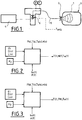
- the filling station illustrated schematically and partially at the figure 1 comprises an injector 2 located at the end of a hose 5 intended to be connected to the orifice of a reservoir 1 to be filled.
- the hose 5 is connected via at least one valve system 6 to a source 4 of gas under pressure.
- the method preferably uses a modeling of the macroscopic thermal phenomena that occur within the system comprising the hose 5, the tank 1 and its environment during filling of the tank 1.
- the model preferably uses simplifying assumptions to reduce the calculation time while maintaining a good approximation of the phenomena considered.
- the determination of the intensity of each of the phenomena must be related to the characteristic parameters of the tanks to be filled and communicated to the station by means of standardized communication according to the SAE standard.
- the geometric dimensions of the tank 1 are assumed to be known (length, diameter, surface area (s), etc.).
- the model relies on a Nusselt correlation to determine the evolution of the temperature in the reservoir.
- This Nusselt correlation is expressed through two adimensionnated numbers: the Reynolds number relative to the forced internal convection and the Rayleigh number relative to the internal natural convection.
- these two adimensionnated numbers are expressed according to an expression involving the geometry of the reservoir, in particular the ratios L int / Dint and Dint / di.
- Lint being the internal length of the tank in meter, Dint the internal diameter of the tank and di the diameter of the injector di in meter (known).
- This method makes it possible to fill any hydrogen vehicle efficiently and quickly without measuring the temperature of the gas in the tank.
- the model for estimating the temperature of the gas in the tank 1 is a mathematical model called "zero dimension" ("0D").
- the temperature of the gas T (0) in the tank 1 before filling is approximated at room temperature Tamb because the tank 1 is assumed to thermodynamic equilibrium before filling.
- the method for estimating the temperature T (t) is modeled according to a compromise between its precision and its complexity (the latter conditioning its speed of computation).
- the main physical phenomena involved in the filling are: the compression and the injection of gas into the tank 1, the internal convection between the gas and the wall 3 of the tank 1, the external convection between the wall 3 of the tank 1 and the ambient air and radiation from the outer wall 3 of the tank 1 to the atmosphere.
- This model can be broken down into two subsystems: 1) the gas (hydrogen) and 2) the tank wall (liner + composite when it is a composite tank).
- the gas will exchange heat with the wall 3 of the tank 1 which itself will interact with the external environment.
- Each subsystem is therefore characterized with its own variables of temperature, pressure and mass. These subsystems interact with each other and mutually exchange heat to find a balance.
- the gas injected into the tank 1 from the source 4 has its own enthalpy.
- the amount of heat exchanged is related to the exchange surface. Therefore, it is essential to know the characteristic dimensions of the tank 1 that are the internal diameter Dint and the internal length Lint.
- the forced convection linked to the movement generated by the flow of gas entering the reservoir will be characterized from the injection diameter di of the injector 2 at the neck of the reservoir (at the orifice).
- the composite wall 3 of a type IV reservoir known in itself is considered homogeneous with respect to heat exchange (homogeneous single wall whose properties correspond to the weighted average of each component , the temperature in the thickness of the wall 3 is modeled by a gradient).
- the device has a flow measurement of the gas entering the tank 1.
- the mass m (t) of the gas injected in real time in the tank 1 is an input data and the pressure P (t) gas in the tank is an output data (calculated).
- This formula is preferred to the ideal gas law for a wide range of pressures.
- Equations 3, 4 and 5 make it possible to determine the three unknowns (P, T, Tw).
- the chosen numerical scheme can be a diagram of the type "explicit time of Euler”. There is no discretization of the space if the model is of the zero dimension type (0D).
- thermodynamic parameters Cp, ⁇ , h, Z can be calculated precisely by interpolating the data grids of NIST knowing the pressure and the temperature (P and T).
- NIST is the abbreviation of the National Institute of Standards and Technology.
- the indices t and t-1 respectively correspond to the present instant t and the previous instant t-1.
- the derivatives are replaced by variations between two consecutive instants.
- the value of the specific thermal capacity of the gas is calculated at (t-1) in place of the instant (t). Indeed, not yet knowing the temperature T (t) it is not possible to read in the tables the value of Cp (t). This can be done because the specific heat capacity varies little between two close moments.
- This equation is the expression of the temperature T (t) of the gas at the discretized instant t that can be implemented in a "software sensor” algorithm.
- Equations 6, 7 8 make it possible to calculate the three unknowns T (t), T w (t) and P (t) (or m (t)) by iterative calculation.
- the heat exchange coefficients determine the temperature rise profile during filling are expressed via adimensionnated numbers.
- the convection is no longer mixed (forced + natural) but only natural in the tank.
- the grouping that governs natural convection is the Grashof number (Gr) but the currently accepted correlations involve the Rayleigh number (Ra).
- the number of the Nusselt defines the ratio of heat transmitted by conduction and convection at the limit of a wall and a fluid.
- the thermal conductivity ⁇ is a property of the gas evolving with the pressure P and the temperature T and can be precisely calculated for example by interpolation of the NIST data.
- a is a dimensionless coefficient function of the ratio (Lint / Dint) between the internal length of the reservoir Lint in meters and the internal diameter of the reservoir Dint in meters
- c being a coefficient without dimension depending on the ratio (Dint / di) between the internal diameter of the reservoir Dint in meter and the diameter of the injector di in meter
- a, b, c and d being positive real numbers without dimension, a being between 0 and 0.2, b being between 0.2 and 0.5, c being between 0 and 0.3 and d being between 0.5 and 0.9.
- the inventors have observed that the Reynolds number and its associated coefficients (c and d) make it possible to adjust the maximum temperature reached by the gas during a filling.
- the Rayleigh number and the associated coefficients (a and b) determine the temperature evolution profile of the gas, in particular outside the filling phase, although the two actions are combined during filling.
- the Reynolds number (Red) (dimensionless) relative to the forced convection in the tank 1 is preferably between 5.6 ⁇ 10 4 and 2.0 ⁇ 10 6 .
- the number of Rayleigh (Radint) (dimensionless) relative to the internal natural convection in the tank (1) is preferably between 8.0 ⁇ 10 8 and 1.0 ⁇ 10 12 .
- the relative error on the maximum temperature reached at the end of filling is less than 3%. This results in a mean deviation from the measured temperature of about 8K (the standard deviation being 3.45K).
- the method makes it possible to calculate the mass of gas (t) at each instant in the tank 1 and thus the mass transferred since the beginning of filling. Indeed, knowing the pressure, the volume and having an estimate of the temperature, the law of the real gases makes it possible to deduce the quantity of matter and thus the mass knowing the molar mass of the hydrogen.
- the temperature estimation during filling can be advantageously used in filling stations which do not use dynamic communication with the vehicle (the pressure and the temperature in the tank of the connected vehicle are not communicated to the vehicle). the station).
Description
La présente invention concerne procédé de remplissage d'un réservoir composite.The present invention relates to a method of filling a composite tank.
L'invention concerne plus particulièrement un procédé de remplissage d'un réservoir composite de type IV délimité par une paroi de forme générale cylindrique et de dimension connues avec un gaz carburant sous pression, notamment de l'hydrogène gazeux, le gaz étant injecté dans le réservoir via un injecteur de diamètre connu, dans lequel la température T(t) moyenne du gaz dans le réservoir est estimée en temps réel en fonction du temps t au cours du remplissage, le procédé comprenant, avant le remplissage, une étape de détermination de la température initiale T(0) du gaz dans le réservoir, une étape de détermination de la pression initiale P(0) du gaz dans le réservoir, une étape de détermination de la température moyenne initiale de la paroi du réservoir Tw(0) et une étape de détermination de la masse de gaz initiale dans le réservoir m(0), le procédé comprenant, au cours du remplissage, une étape de détermination de l'enthalpie he(t) du gaz entrant dans le réservoir en fonction du temps et une étape de détermination de la masse de gaz m(t) introduite dans le réservoir en fonction du temps ou, respectivement, une étape de détermination de la pression P(t) dans le réservoir en fonction du temps, le procédé comprenant une étape de détermination de la température moyenne du gaz T(t) à l'instant t dans le réservoir en degré K.The invention more particularly relates to a method for filling a type IV composite tank delimited by a generally cylindrical wall of known size with a fuel gas under pressure, in particular hydrogen gas, the gas being injected into the reservoir via an injector of known diameter, wherein the average temperature T (t) of the gas in the tank is estimated in real time as a function of time t during filling, the method comprising, before filling, a step of determining the the initial temperature T (0) of the gas in the tank, a step of determining the initial pressure P (0) of the gas in the tank, a step of determining the initial average temperature of the tank wall T w (0) and a step of determining the initial mass of gas in the tank m (0), the method comprising, during filling, a step of determining the enthalpy h e (t) of the gas ent in the tank as a function of time and a step of determining the mass of gas m (t) introduced into the tank as a function of time or, respectively, a step of determining the pressure P (t) in the tank in function time, the method comprising a step of determining the average temperature of the gas T (t) at time t in the tank in degree K.
Le remplissage de réservoirs de gaz à haute pression (tel que de l'hydrogène à une pression comprise entre 300 et 800bar) est soumis à des contraintes antagonistes. En effet, le remplissage de réservoirs de véhicules doit être réalisé dans un temps minimum (quelques minutes) tout en maximisant le taux de remplissage et en limitant le refroidissement du gaz injecté.The filling of high pressure gas tanks (such as hydrogen at a pressure between 300 and 800 bar) is subject to conflicting constraints. Indeed, the filling of vehicle tanks must be performed in a minimum time (a few minutes) while maximizing the filling rate and limiting the cooling of the injected gas.
La connaissance de la température du gaz dans le réservoir au cours du remplissage est préférable pour éviter un échauffement excessif.Knowledge of the temperature of the gas in the tank during filling is preferred to avoid overheating.
Cependant, dans un modèle de remplissage dit « sans communication », cette température n'est pas mesurée par un capteur de température et doit donc être calculée (estimée).However, in a so-called "no communication" filling model, this temperature is not measured by a temperature sensor and must therefore be calculated (estimated).
Un tel procédé de remplissage est connu de
Le procédé pourra utiliser notamment les paramètres évoqués dans la norme « SAE » concernant le remplissage des réservoirs d'hydrogène de véhicules.The method may use in particular the parameters mentioned in the "SAE" standard concerning the filling of the hydrogen tanks of vehicles.
Ce capteur logiciel peut notamment être utilisé sur les stations de remplissage dans le cas où il n'y a pas de communication dynamique avec le véhicule, c'est-à-dire quand la pression et la température dans le réservoir du véhicule à remplir ne sont pas communiquées à la station de remplissage.This software sensor can in particular be used on the filling stations in the case where there is no dynamic communication with the vehicle, that is to say when the pressure and the temperature in the tank of the vehicle to be filled do not are not communicated to the filling station.
Actuellement la technologie privilégiée consiste à déterminer des rampes d'augmentation de pression dans le réservoir en fonction de la capacité de la station à refroidir le gaz injecté à l'entrée du réservoir. Cependant, ces recommandations imposent un refroidissement exagéré pour être sûr que la température dans le réservoir reste toujours inférieure à la limite réglementaire (85°C).Currently the preferred technology is to determine pressure increase ramps in the tank depending on the capacity of the station to cool the gas injected at the tank inlet. However, these recommendations impose an excessive cooling to be sure that the temperature in the tank remains always lower than the regulatory limit (85 ° C).
Ce refroidissement excessif (coûteux) peut être réduit grâce au procédé selon l'invention.This excessive (expensive) cooling can be reduced by the process according to the invention.
Le procédé selon l'invention peut notamment être mis en oeuvre dans un procédé comprenant une étape préliminaire connue de pré-remplissage dans laquelle un jet de pression est réalisé dans un temps bref (quelques secondes) pour estimer les propriétés du réservoir telles que la masse, la pression et la température du gaz au sein du réservoir avant le remplissage.The process according to the invention may in particular be carried out in a process comprising a known preliminary pre-filling stage in which a pressure jet is produced in a short time (a few seconds) in order to estimate the properties of the reservoir such as the mass. , the pressure and temperature of the gas within the tank before filling.
Après cette étape préliminaire, une étape suivante peut être constituée du remplissage proprement dit. Au cours de celle-ci, l'évolution de la température du gaz dans le réservoir est estimée en temps réel pour en déduire la masse (ou la pression) et donc la masse volumique du gaz à chaque instant. Ce procédé, associé à une stratégie de contrôle du remplissage permet d'arrêter le remplissage sur un critère de masse, de masse volumique ou de pression finale à atteindre.After this preliminary step, a next step may consist of the actual filling. During this, the evolution of the gas temperature in the tank is estimated in real time to deduce the mass (or pressure) and therefore the density of the gas at each moment. This method, combined with a filling control strategy, makes it possible to stop the filling on a criterion of mass, density or final pressure to be achieved.
Un but de la présente invention est de pallier tout ou partie des inconvénients de l'art antérieur relevés ci-dessus.An object of the present invention is to overcome all or part of the disadvantages of the prior art noted above.
A cette fin, le procédé selon l'invention, par ailleurs conforme à la définition générique qu'en donne le préambule ci-dessus, est essentiellement caractérisé en ce que cette température moyenne T(t) est exprimée comme une fonction du premier degré de la température moyenne du gaz T(t-1) à l'instant précédent (t-1) et d'un coefficient d'échange chaleur kg(t-1) convectif entre le gaz et la paroi interne du réservoir à l'instant (t-1) en W.m-2.K-1, dans lequel le coefficient d'échange chaleur kg(t-1) est donné par la relation kg=(λg/Dint).Nuint dans laquelle λg est la conductivité thermique du gaz dans le réservoir en W.m-1.K-1, Dint est le diamètre interne du réservoir en mètre et Nuint le nombre de Nusselt du gaz dans le réservoir (sans dimension), et dans lequel le nombre de Nusselt du gaz est exprimé en fonction du nombre de Reynolds (Red) (sans dimension) relatif à la convection forcée dans le réservoir et du nombre de Rayleigh (Radint) (sans dimension) relatif à la convection naturelle interne dans le réservoir selon une formule Nuint= a.Radintb + c.Redddans laquelle a est un coefficient sans dimension fonction du rapport (Lint/Dint) entre la longueur interne du réservoir Lint en mètre et le diamètre interne du réservoir Dint en mètre, c étant un coefficient sans dimension fonction du rapport (Dint/di) entre le diamètre interne du réservoir Dint en mètre et le diamètre de l'injecteur di en mètre, a, b, c et d étant des nombres réels positifs sans dimension, a étant compris entre 0 et 0,2, b étant compris entre 0,2 et 0,5, c étant compris entre 0 et 0,3 et d étant compris entre 0.5 et 0.9.For this purpose, the method according to the invention, moreover in accordance with the generic definition given in the preamble above, is essentially characterized in that this average temperature T (t) is expressed as a function of the first degree of the average temperature of the gas T (t-1) at the previous instant (t-1) and a convective heat exchange coefficient k g (t-1) between the gas and the inner wall of the tank at the instant (t-1) in Wm -2 .K -1 , in which the heat exchange coefficient k g (t-1) is given by the relation k g = (λg / Dint) .Nuint in which λg is the thermal conductivity of the gas in the tank in Wm -1 .K -1 , Dint is the internal diameter of the tank in meter and Nuint the number of Nusselt gas in the tank (dimensionless), and in which the number of Nusselt gas is expressed as a function of the Reynolds number (Red) (dimensionless) relative to the forced convection in the reservoir and the Rayleigh number (Radint) (dimensionless) relative to the internal natural convection in the reservoir according to a formula Nuint = a. Radint b + c.Red d in which a is a dimensionless coefficient depending on the ratio (Lint / Dint) between the internal length of the reservoir Lint in meters and the internal diameter of the reservoir Dint in meters, c being a dimensionless coefficient depending on the ratio (Dint / di) between the internal diameter of the reservoir Dint in meters and the diameter of the injector di in meters, a, b, c and d being positive real numbers without dimension, a being between 0 and 0.2 , b being between 0.2 and 0.5, c being between 0 and 0.3 and d being between 0.5 and 0.9.
Par ailleurs, des modes de réalisation de l'invention peuvent comporter l'une ou plusieurs des caractéristiques suivantes :
- le coefficient a sans dimension fonction du rapport (Lint/Dint) est donné par la formule :
a= a1 * exp(a2*(Lint/Dint)) dans laquelle « exp » signifie la fonction exponentielle, avec a1 compris entre 0 et 0,04 et a2 compris entre 0,1 et 0,3- le coefficient c sans dimension fonction du rapport (Dint/di) est donné par la formule : c = c1 * exp(c2 * (Dint/d)) dans laquelle « exp » signifie la fonction exponentielle, c1 étant compris entre 0 et 0,05 et c2 étant compris entre 0,5 et 3,
- la paroi du réservoir composite comprend un liner plastique et une couche de matériau composite et est assimilée à une paroi homogène pour modéliser sa température (Tw), c'est-à-dire que la capacité calorifique et la masse de la paroi sont les moyennes de celles des deux constituants de la paroi que sont le liner et la couche de composite,
- la température moyenne du gaz T(t) est déterminée en temps réel par la résolution numérique de deux bilans enthalpiques : un premier bilan enthalpique appliqué au gaz injecté dans le réservoir et un second bilan enthalpique appliqué à la paroi du réservoir, en utilisant l'équation d'état des gaz réels appliquée au gaz dans le réservoir, les propriétés thermophysiques du gaz tel que le facteur de compressibilité Z, la capacité thermique massique cp et l'enthalpie massique h du gaz étant connues,
- la masse de gaz dans le réservoir est déterminée en temps réel par la résolution numérique de deux bilans enthalpiques : un premier bilan enthalpique appliqué au gaz injecté dans le réservoir et un second bilan enthalpique appliqué à la paroi du réservoir, en utilisant l'équation d'état des gaz réels appliquée au gaz dans le réservoir, les propriétés thermophysiques du gaz tel que le facteur de compressibilité Z, la capacité thermique massique cp et l'enthalpie massique h du gaz étant connues,
- la pression moyenne du gaz P(t) dans le réservoir est déterminée en temps réel par la résolution numérique de deux bilans enthalpiques : un premier bilan enthalpique appliqué au gaz injecté dans le réservoir et un second bilan enthalpique appliqué à la paroi du réservoir, en utilisant l'équation d'état des gaz réels appliquée au gaz dans le réservoir, les propriétés thermophysiques du gaz tel que le facteur de compressibilité Z, la capacité thermique massique cp et l'enthalpie massique h du gaz étant connues,
- la température moyenne de la paroi du réservoir Tw(t) est déterminée en temps réel par la résolution numérique de deux bilans enthalpiques : un premier bilan enthalpique appliqué au gaz injecté dans le réservoir et un second bilan enthalpique appliqué à la paroi du réservoir, en utilisant l'équation d'état des gaz réels appliquée au gaz dans le réservoir, les propriétés thermophysiques du gaz tel que le facteur de compressibilité Z, la capacité thermique massique Cp et l'enthalpie massique h du gaz étant connues,
- le réservoir a un rapport (Lint/Dint) entre la longueur interne du réservoir Lint en mètre et le diamètre interne du réservoir Dint en mètre compris entre 1,5 et 7 et de préférence compris entre 1,8 et 6,6,
- le rapport (Dint/di) entre le diamètre interne du réservoir Dint en mètre et le diamètre di de l'injecteur (2) en mètre est compris entre 30 et 80 et de préférence compris entre 35,0 et 72,3,
- le nombre de Reynolds (Red) (sans dimension) relatif à la convection forcée dans le réservoir est compris entre 5,6.104 et 2,0.106,
- le nombre de Rayleigh (Radint) (sans dimension) relatif à la convection naturelle interne dans le réservoir est compris entre 8,0.108 et 1,0.1012.
- the dimensionless coefficient function of the ratio (Lint / Dint) is given by the formula:
a = a1 * exp (a2 * (L int / D int )) where "exp" means the exponential function, with a1 between 0 and 0.04 and a2 between 0.1 and 0.3- the dimensionless coefficient c function of the ratio (Dint / di) is given by the formula: c = c1 * exp (c2 * (Dint / d)) in which "exp" signifies the exponential function, c1 being between 0 and 0 , 05 and c2 being between 0.5 and 3,
- the wall of the composite tank comprises a plastic liner and a layer of composite material and is assimilated to a homogeneous wall to model its temperature (T w ), that is to say that the heat capacity and the mass of the wall are the average of those of the two constituents of the wall which are the liner and the layer of composite,
- the average temperature of the gas T (t) is determined in real time by the numerical resolution of two enthalpic balances: a first enthalpy balance applied to the gas injected into the reservoir and a second enthalpy balance applied to the wall of the reservoir, using the the state equation of the real gases applied to the gas in the tank, the thermophysical properties of the gas such as the compressibility factor Z, the specific heat capacity cp and the gas mass enthalpy h being known,
- the mass of gas in the reservoir is determined in real time by the numerical resolution of two enthalpic balances: a first enthalpy balance applied to the gas injected into the reservoir and a second enthalpy balance applied to the wall of the reservoir, using the equation d the state of the real gases applied to the gas in the tank, the thermophysical properties of the gas such as the compressibility factor Z, the specific heat capacity cp and the mass enthalpy h of the gas being known,
- the average pressure of the gas P (t) in the reservoir is determined in real time by the numerical resolution of two enthalpic balances: a first enthalpy balance applied to the gas injected into the reservoir and a second enthalpy balance applied to the wall of the reservoir, in using the real gas state equation applied to the gas in the reservoir, the thermophysical properties of the gas such as the compressibility factor Z, the specific heat capacity c p and the gas mass enthalpy h being known,
- the mean temperature of the wall of the reservoir Tw (t) is determined in real time by the numerical resolution of two enthalpic balances: a first enthalpy balance applied to the gas injected into the reservoir and a second enthalpy balance applied to the wall of the reservoir, in using the real gas state equation applied to the gas in the reservoir, the thermophysical properties of the gas such as the compressibility factor Z, the specific heat capacity Cp and the gas mass enthalpy h being known,
- the reservoir has a ratio (Lint / Dint) between the internal length of the reservoir Lint in meters and the internal diameter of the reservoir Dint in meters of between 1.5 and 7 and preferably between 1.8 and 6.6,
- the ratio (Dint / di) between the internal diameter of the reservoir Dint in meters and the diameter di of the injector (2) in meters is between 30 and 80 and preferably between 35.0 and 72.3,
- Reynolds number (Red) (dimensionless) for the forced convection in the reservoir is between 5,6.10 4 and 2.0x10 6,
- the number of Rayleigh (Radint) (dimensionless) relative to the internal natural convection in the tank is between 8.0.10 8 and 1.0.10 12 .
L'invention peut concerner également tout dispositif ou procédé alternatif comprenant toute combinaison des caractéristiques ci-dessus ou ci-dessous.The invention may also relate to any alternative device or method comprising any combination of the above or below features.
D'autres particularités et avantages apparaîtront à la lecture de la description ci-après, faite en référence aux figures dans lesquelles :
- la
figure 1 représente une vue schématique et partielle illustrant un exemple de station de remplissage pouvant mettre en oeuvre le procédé selon l'invention, - les
figures 2 et 3 représentent des vues schématiques et partielles illustrant respectivement deux exemples de fonctionnement possibles du procédé selon l'invention.
- the
figure 1 represents a schematic and partial view illustrating an example filling station that can implement the method according to the invention, - the
Figures 2 and 3 are schematic and partial views respectively illustrating two examples of possible operation of the method according to the invention.
La station de remplissage illustrée schématiquement et partiellement à la
Le procédé utilise de préférence une modélisation des phénomènes thermiques macroscopiques qui interviennent au sein du système comprenant le flexible 5, le réservoir 1 et son environnement lors du remplissage du réservoir 1.The method preferably uses a modeling of the macroscopic thermal phenomena that occur within the system comprising the
Les propriétés physiques du gaz (ex : hydrogène) à la sortie de l'injecteur 2 ou juste en amont de celui-ci sont supposées connues (pression P et température T en temps réel). Ceci permet de connaître l'enthalpie h du gaz à cet endroit.The physical properties of the gas (eg hydrogen) at the outlet of the
Comme détaillé ci-après, le modèle utilise de préférence des hypothèses simplificatrices pour réduire le temps de calcul tout en conservant une bonne approximation des phénomènes considérés.As detailed below, the model preferably uses simplifying assumptions to reduce the calculation time while maintaining a good approximation of the phenomena considered.
De plus, pour répondre à l'interopérabilité souhaitée des stations, la détermination de l'intensité de chacun des phénomènes doit être reliée à des paramètres caractéristiques des réservoirs à remplir et communiqués à la station grâce à la communication standardisée selon le standard SAE. Ainsi, les dimensions géométriques du réservoir 1 sont supposées connues (longueur, diamètre, surface(s)...).In addition, in order to respond to the desired interoperability of the stations, the determination of the intensity of each of the phenomena must be related to the characteristic parameters of the tanks to be filled and communicated to the station by means of standardized communication according to the SAE standard. Thus, the geometric dimensions of the
Selon une caractéristique avantageuse, le modèle s'appuie sur une corrélation de Nusselt pour déterminer l'évolution de la température dans le réservoir. Cette corrélation de Nusselt est exprimée au travers de deux nombres adimensionnés : le nombre de Reynolds relatif à la convection forcée interne et le nombre de Rayleigh relatif à la convection naturelle interne. Selon une particularité particulièrement avantageuse ces deux nombres adimensionnés sont exprimés selon une expression faisant intervenir la géométrie du réservoir, en particulier les rapports Lint/Dint et Dint/di.According to an advantageous characteristic, the model relies on a Nusselt correlation to determine the evolution of the temperature in the reservoir. This Nusselt correlation is expressed through two adimensionnated numbers: the Reynolds number relative to the forced internal convection and the Rayleigh number relative to the internal natural convection. According to a particularly advantageous particularity these two adimensionnated numbers are expressed according to an expression involving the geometry of the reservoir, in particular the ratios L int / Dint and Dint / di.
Lint étant la longueur interne du réservoir en mètre, Dint le diamètre interne du réservoir et di le diamètre de l'injecteur di en mètre (connu).Lint being the internal length of the tank in meter, Dint the internal diameter of the tank and di the diameter of the injector di in meter (known).
Ce procédé permet de remplir efficacement et rapidement n'importe quel véhicule hydrogène sans mesurer la température du gaz dans le réservoir.This method makes it possible to fill any hydrogen vehicle efficiently and quickly without measuring the temperature of the gas in the tank.
De préférence, le modèle d'estimation de la température du gaz dans le réservoir 1 est un modèle mathématique dit à « zéro dimension » (« 0D »).Preferably, the model for estimating the temperature of the gas in the
Un tel modèle considère que le gaz (hydrogène dans notre exemple) entrant dans le réservoir 1 est immédiatement et parfaitement mélangé avec le gaz présent. De plus, la température T(t) de l'hydrogène dans le réservoir 1 est considérée homogène en tout point. Ainsi, et comme accepté par les normes ou projets de normes actuelles, la température T(t) du gaz dans le réservoir (1), qu'elle soit estimée ou mesurée, est considérée comme une température moyenne du gaz dans le réservoir 1.Such a model considers that the gas (hydrogen in our example) entering the
De plus, la température du gaz T(0) dans le réservoir 1 avant remplissage est approximée à la température ambiante Tamb car le réservoir 1 est supposé à l'équilibre thermodynamique avant le remplissage.In addition, the temperature of the gas T (0) in the
Le procédé d'estimation de la température T(t) est modélisé selon un compromis entre sa précision et sa complexité (cette dernière conditionnant sa vitesse de calcul).The method for estimating the temperature T (t) is modeled according to a compromise between its precision and its complexity (the latter conditioning its speed of computation).
Les principaux phénomènes physiques intervenant lors du remplissage sont : la compression et l'injection de gaz dans le réservoir 1, la convection interne entre le gaz et la paroi 3 du réservoir 1, la convection externe entre la paroi 3 du réservoir 1 et l'air ambiant et le rayonnement de la paroi 3 externe du réservoir 1 vers l'atmosphère.The main physical phenomena involved in the filling are: the compression and the injection of gas into the
Ce modèle peut être décomposé en deux sous-systèmes : 1) le gaz (hydrogène) et 2) la paroi du réservoir (liner + composite lorsqu'il s'agit d'un réservoir composite).This model can be broken down into two subsystems: 1) the gas (hydrogen) and 2) the tank wall (liner + composite when it is a composite tank).
Ainsi, le gaz va échanger de la chaleur avec la paroi 3 du réservoir 1 qui elle-même va interagir avec le milieu extérieur. Chaque sous-système est donc caractérisé avec ses propres variables de température, pression et masse. Ces sous-systèmes interagissent entre eux et échangent mutuellement de la chaleur afin de trouver un équilibre.Thus, the gas will exchange heat with the
De plus, lors du remplissage, le gaz injecté dans le réservoir 1 depuis la source 4 a sa propre enthalpie he.In addition, during filling, the gas injected into the
La quantité de chaleur échangée est liée à la surface d'échange. Par conséquent, il est primordial de connaître les dimensions caractéristiques du réservoir 1 que sont le diamètre interne Dint et la longueur interne Lint. La convection forcée liée au mouvement engendré par le débit de gaz entrant dans le réservoir sera caractérisée à partir du diamètre d'injection di de l'injecteur 2 au niveau du col du réservoir (au niveau de l'orifice).The amount of heat exchanged is related to the exchange surface. Therefore, it is essential to know the characteristic dimensions of the
Pour déterminer la température T du gaz dans le réservoir 1, il faut considérer les effets prépondérants se produisant au sein du système considéré pendant la phase de remplissage et ayant un impact sur cette température. Les phénomènes considérés sont
- l'admission du gaz, c'est-à-dire l'état thermodynamique de gaz injecté dans le réservoir 1 (qui diffère de celui présent initialement),
- la compression du gaz dans le réservoir 1 (pour l'hydrogène, le gaz se réchauffe en se comprimant),
- la convection interne (seule la paroi 3 limite l'échange entre l'intérieur et l'extérieur du réservoir 1 et donc la convection interne permet à la chaleur d'être évacuée vers l'extérieur),
- la convection externe (entre l'extérieur et le réservoir 1),
- le rayonnement entre la paroi 3 extérieure et l'air extérieur (échange de la chaleur par rayonnement avec l'atmosphère du fait de la différence entre la température Tw de la paroi 3 et la température extérieure ambiante Tamb).
- the admission of gas, that is to say the thermodynamic state of gas injected into the tank 1 (which differs from that initially present),
- the compression of the gas in the tank 1 (for hydrogen, the gas heats up by compressing),
- the internal convection (only the
wall 3 limits the exchange between the inside and the outside of thetank 1 and thus the internal convection allows the heat to be evacuated towards the outside), - external convection (between the outside and the tank 1),
- the radiation between the
outer wall 3 and the outside air (exchange of heat by radiation with the atmosphere due to the difference between the temperature Tw of thewall 3 and the ambient outside temperature Tamb).
Un phénomène prépondérant manque dans cette liste. Il s'agit de la conduction dans la paroi 3 du réservoir 1. Le paragraphe suivant donne l'explication et les hypothèses associées.A preponderant phenomenon is missing in this list. This is the conduction in the
Selon une particularité avantageuse la paroi 3 composite d'un réservoir de type IV connu en soit (liner + renfort de fibres) est considérée homogène en ce qui concerne les échanges thermiques (paroi unique homogène dont les propriétés correspondent à la moyenne pondérée de chaque composant, la température dans l'épaisseur de la paroi 3 est modélisée par un gradient).According to an advantageous feature, the
Tous les phénomènes physiques décrits précédemment peuvent être transcrits en équations mathématiques. Deux bilans d'énergie et une équation d'état peuvent permettre de déduire une expression de la température T(t) en fonction de données connues.All the physical phenomena described above can be transcribed into mathematical equations. Two energy balances and one state equation can be used to deduce an expression of the temperature T (t) as a function of known data.
Comme illustré à la
- les données constantes que sont : les propriétés physiques de l'hydrogène (H2), la géométrie du réservoir (Dint, Lint,...), le diamètre di de l'injecteur et les propriétés physiques des parois 3,
- les conditions initiales (variables) que sont : la pression initiale du gaz dans le réservoir P(0), la température initiale du gaz dans le réservoir 1 T(0), la température initiale de la paroi du réservoir Tw(0) et la masse initiale de gaz dans le réservoir m(0),
- l'enthalpie du gaz entrant he(t) et la pression P(t) mesurée au plus proche du réservoir 1, par exemple au niveau du flexible 5.
- the constant data that are: the physical properties of hydrogen (H2), the geometry of the reservoir (Dint, Lint, ...), the diameter di of the injector and the physical properties of the
walls 3, - the initial conditions (variables) that are: the initial pressure of the gas in the tank P (0), the initial temperature of the gas in the tank 1 T (0), the initial temperature of the tank wall Tw (0) and the initial mass of gas in the tank m (0),
- the enthalpy of the entering gas he (t) and the pressure P (t) measured closest to the
tank 1, for example at the level of thehose 5.
Ces données sont connues, déterminées ou mesurées aisément.These data are known, determined or easily measured.
A partir de ces données d'entrée le modèle peut calculer les données de sortie suivantes :
- la température T(t) du gaz dans le réservoir 1 à l'instant t,
- la masse m(t) du gaz dans le réservoir 1 à l'instant t,
- la température Tw(t) de la paroi du réservoir 1 à l'instant t.
- the temperature T (t) of the gas in the
tank 1 at time t, - the mass m (t) of the gas in the
tank 1 at time t, - the temperature Tw (t) of the wall of the
tank 1 at time t.
Dans la variante de la
Une première équation de bilan d'énergie peut faire le bilan enthalpique du gaz dans le réservoir 1. Trois termes ont un impact sur la variation d'enthalpie : le premier vient de la compression du gaz, le second représente la convection entre le gaz et la paroi interne du réservoir et le troisième terme provient de la quantité de gaz injecté dans le réservoir.
On obtient ![]()
- m = la masse de gaz dans le réservoir (en kg)
- dh/dt = la dérivée par rapport au temps de l'enthalpie massique du gaz dans le réservoir (en J.kg-1.s-1)
- V= le volume du réservoir (en m3)
- dP/dt = la dérivée par rapport au temps de la pression du gaz dans le réservoir (en Pa.s-1)
- kg= le coefficient d'échange convectif entre le gaz et la paroi interne (en W.m-2.K-1)
- Si= la surface interne de la paroi du réservoir (en m2)
- m = la masse du gaz dans le réservoir (en kg)
- he = l'enthalpie massique du gaz entrant dans le réservoir (en J.kg-1)
- h = l'enthalpie massique du gaz dans le réservoir (en J.kg-1)
- Twi = température de la paroi interne du réservoir en contact direct avec le gaz =(T+Tw)/2. Cette température est supposée égale à la moyenne de la température T du gaz et de celle Tw de la paroi (en K)
- m = le débit de masse entrant dans le réservoir (kg.s-1)
We obtain
- m = the mass of gas in the tank (in kg)
- dh / dt = the time derivative of the mass enthalpy of the gas in the reservoir (in J.kg -1 .s -1 )
- V = the volume of the tank (in m 3 )
- dP / dt = the derivative with respect to the time of the pressure of the gas in the tank (in Pa.s -1 )
- kg = the convective exchange coefficient between the gas and the inner wall (in Wm -2 .K -1 )
- Si = the internal surface of the tank wall (in m 2 )
- m = the mass of the gas in the tank (in kg)
- he = the mass enthalpy of the gas entering the tank (in J.kg -1 )
- h = the mass enthalpy of the gas in the tank (in J.kg -1 )
- T wi = temperature of the internal wall of the tank in direct contact with the gas = (T + T w ) / 2. This temperature is assumed equal to the average of the temperature T of the gas and that T w of the wall (in K)
- m = the mass flow entering the reservoir (kg.s -1 )
Pour calculer correctement la valeur de l'enthalpie massique la définition générale de l'enthalpie h d'un gaz réel est utilisée (cf. ci-dessous) : ![]()
- dh = la variation de l'enthalpie du fluide considéré (en J.kg-1)
- Cp= la capacité thermique massique à pression constante du fluide considéré (en J.kg-1.K-1)
- dT = la variation de température du fluide considéré (en K)
- β= le coefficient de compressibilité isochore du fluide considéré (en K-1)
- T= la température du fluide considéré en (en K)
- dP= la variation de pression du fluide considéré (en Pa)
- ρ = la masse volumique du fluide considéré (en kg.m-3)
- dh = the variation of the enthalpy of the fluid considered (in J.kg -1 )
- Cp = the constant heat capacity at constant pressure of the fluid in question (in J.kg -1 .K -1 )
- dT = the temperature variation of the fluid under consideration (in K)
- β = the isochoric compressibility coefficient of the fluid under consideration (in K -1 )
- T = the temperature of the fluid considered in (in K)
- dP = the pressure variation of the fluid considered (in Pa)
- ρ = the density of the fluid considered (in kg.m -3 )
En faisant intervenir la température du gaz T, la température Tw de la paroi et P la pression P du gaz dans le réservoir 1 on obtient (équation 3) : ![]()
![]()
La seconde équation définissant le bilan enthalpique appliqué à la paroi 3 du réservoir donne l'équation 4 suivante (les trois termes à droite de l'équation représentent respectivement la chaleur échangée avec la paroi par convection interne, par convection externe et par rayonnement). 
- kg = le coefficient d'échange convectif entre la paroi externe et l'air embiant (en W.m-2.K-1)
- Se = la surface externe de la paroi du réservoir (en m2)
- ε= l'émissivité de la paroi externe du réservoir (sans dimension)
- σ = la constante de Stéphan-Boltzmann (en W.m-2.K-4= 5,67.10-8)
- Tamb = la température ambiante (en K)
- Twe = la température de la surface externe de la paroi du réservoir. Cettte température est égale à la moyenne de la température ambiante Tamb et celle Tw de la paroi Twe=(Tw+Tamb)/2 (en K)
- Twi= la température de la surface interne de la paroi du réservoir (en K)
- Si = la surface interne de la paroi du réservoir (en m2)
- Cpw = la capacité thermique massique de la paroi du réservoir (en J.kg-1.K-1)
- k g = the convective exchange coefficient between the outer wall and the air embying (in Wm -2 .K -1 )
- S e = the external surface of the tank wall (in m 2 )
- ε = the emissivity of the outer wall of the reservoir (dimensionless)
- σ = the Stephan-Boltzmann constant (in Wm -2 .K -4 = 5,67.10 -8 )
- T amb = the ambient temperature (in K)
- T we = the temperature of the external surface of the tank wall. This temperature is equal to the average of the ambient temperature T amb and that T w of the wall T we = (T w + T amb ) / 2 (in K)
- T wi = the temperature of the internal surface of the tank wall (in K)
- S i = the internal surface of the tank wall (in m 2 )
- Cp w = the specific heat capacity of the tank wall (in J.kg -1 .K -1 )
La troisième équation est l'équation d'état appliquée au gaz dans le réservoir 1. ![]()
- n = quantité de matière dans le réservoir en mol
- R = constante des gaz parfaits (=8.314 Pa.m3.mol-1.K-1)
- Z(P,T) est le facteur de compressibilité du gaz réel considéré (sans dimension), fonction de la pression P et de la température T. Cette fonction est connue et tabulée pour chaque gaz en fonction de la température et de la pression.
- n = amount of material in the reservoir in mol
- R = constant of perfect gases (= 8.314 Pa.m 3 .mol -1 .K -1 )
- Z (P, T) is the compressibility factor of the real gas considered (dimensionless), a function of the pressure P and of the temperature T. This function is known and tabulated for each gas as a function of temperature and pressure.
Cette formule est préférée à la loi des gaz parfaits pour une large plage de pressions.This formula is preferred to the ideal gas law for a wide range of pressures.
Il est alors possible d'exprimer la pression P dans le réservoir comme une fonction de m (masse) et T (température) via l'équation 5. ![]()
![]()
Les équations 3, 4 et 5 permettent de déterminer les trois inconnues (P, T, Tw).
Ceci peut être obtenu par discrétisation pour réaliser un calcul pas à pas (par exemple avec le logiciel Matlab®). Le schéma numérique choisi peut être un schéma du type « temps explicite d'Euler ». Il n'y a pas de discrétisation de l'espace si le modèle est du type à zéro dimension (0D).This can be obtained by discretization to perform a step-by-step calculation (for example with the Matlab® software). The chosen numerical scheme can be a diagram of the type "explicit time of Euler". There is no discretization of the space if the model is of the zero dimension type (0D).
Les paramètres thermodynamiques Cp, β, h, Z peuvent être calculés précisément via l'interpolation des grilles de données du NIST connaissant la pression et la température (P et T). Le NIST est l'abréviation du « National Institute of Standards and Technology ».The thermodynamic parameters Cp, β, h, Z can be calculated precisely by interpolating the data grids of NIST knowing the pressure and the temperature (P and T). NIST is the abbreviation of the National Institute of Standards and Technology.
Dans les équations qui suivent, les indices t et t-1 correspondent respectivement à l'instant présent t et l'instant précédent t-1. Les dérivées sont remplacées par des variations entre deux instants consécutifs.In the following equations, the indices t and t-1 respectively correspond to the present instant t and the previous instant t-1. The derivatives are replaced by variations between two consecutive instants.
L'approximation suivante est utilisée : la valeur de la capacité thermique massique du gaz est calculée à (t-1) à la place de l'instant (t). En effet, ne connaissant pas encore la température T(t) il n'est pas possible de lire dans les tables la valeur de Cp(t). Ceci peut être fait car la capacité thermique massique varie peu entre deux instants proches. ![]()
![]()
![]()
![]()
En discrétisant l'équation 3 et en isolant T(t) via l'équation 6, il est possible d'exprimer T(t) sous la forme suivante (équation 7) : 
![]()

![]()
Cette équation est l'expression de la température T(t) du gaz à l'instant t discrétisée pouvant être implémentée dans un algorithme du « capteur logiciel ».This equation is the expression of the temperature T (t) of the gas at the discretized instant t that can be implemented in a "software sensor" algorithm.
De la même manière, il est possible de discrétiser la dernière inconnue, à savoir la température de paroi Tw(t) issue de l'équation 4 : 
- mw= la masse de la paroi en kg
- Cpw=la capacité thermique massique de la paroi (modélisée) en J.kg-1.K-1
- kg(t-1)= le coefficient d'échange convectif à l'instant t-1 entre le gaz et la paroi interne en W.M-2K-1
- ka(t-1)= le coefficient d'échange convectif à l'instant t-1 entre la paroi externe et l'air ambiant en W.m-2.K-1
- Si = la surface interne du réservoir en m2
- Se la surface de la paroi externe du réservoir en m2
- Twi(t-1) la température de la paroi du réservoir en surface interne à l'instant (t-1) en K
- Twe(t-1) la température de la paroi du réservoir en surface externe à l'instant (t-1) en K
- et ε l'émissivité du réservoir (sans dimension) et σ la constante de Boltzmann en W.m-2.k-4= 5,67.10-8
- m w = the mass of the wall in kg
- Cp w = the specific heat capacity of the wall (modeled) in J.kg -1 .K -1
- k g (t-1) = the convective exchange coefficient at time t-1 between the gas and the inner wall in WM -2 K -1
- k a (t-1) = the convective exchange coefficient at time t-1 between the outer wall and the ambient air in Wm -2. K -1
- S i = the internal surface of the tank in m 2
- S e the surface of the external wall of the tank in m 2
- T wi (t-1) the temperature of the tank wall at the inner surface at the moment (t-1) in K
- T we (t-1) the temperature of the tank wall at the external surface at time (t-1) in K
- and ε the emissivity of the reservoir (without dimension) and σ the Boltzmann constant in Wm -2 .k -4 = 5,67.10 -8
Les équations 6, 7 8 permettent de calculer les trois inconnus T(t), Tw(t) et P(t) (ou m(t)) par calcul itératif.
L'expression des coefficients d'échange ka et kg sont détaillés ci-après.The expression of the exchange coefficients k a and k g are detailed below.
Les coefficients d'échange de chaleur déterminent le profil de montée en température lors du remplissage sont exprimés via des nombres adimensionnés. Lorsque le fluide est en écoulement forcé (cas du remplissage), l'écriture sous forme universelle des corrélations de convection fait intervenir trois groupements adimensionnels : le nombre de Nusselt (Nu=(kg.Lc)/ λ), le nombre de Prandtl Pr=(µ.Cp)/ λ) et le nombre de Reynolds Re= V.Lc/v avec :
Nu le nombre de Nusselt (sans dimension), Pr le nombre de Prandtl (sans dimension), Re le nombre de Reynolds (sans dimension), Lc la longueur caractéristique du réservoir (en m), λ la conductivité thermique du gaz en W.m-1.K-1 , v la viscosité cinématique du gaz en m2.s-1.et µ la viscosité dynamique du gaz en kg.m-1.s-1 The heat exchange coefficients determine the temperature rise profile during filling are expressed via adimensionnated numbers. When the fluid is in forced flow (case of the filling), the writing in universal form of the convection correlations involves three adimensional groupings: the number of Nusselt (Nu = (k g .Lc) / λ), the number of Prandtl Pr = (μ.Cp) / λ) and the Reynolds number Re = V.Lc/v with:
Nude the number of Nusselt (dimensionless), Pr the number of Prandtl (dimensionless), Re the Reynolds number (dimensionless), Lc the characteristic length of the reservoir (in m), λ the thermal conductivity of the gas in Wm - 1 .K -1 , v the kinematic viscosity of the gas in m 2 .s -1 .and μ the dynamic viscosity of the gas in kg.m -1 .s -1
Lors des phases où le débit de masse entrant dans le réservoir est nul (pré-remplissage hors pulse de pression, lors d'un changement de buffer etc...) la convection n'est plus mixte (forcée + naturelle) mais seulement naturelle dans le réservoir. Dans ce cas, le groupement qui gouverne la convection naturelle est le nombre de Grashof (Gr) mais les corrélations couramment admises font intervenir le nombre de Rayleigh (Ra).During the phases where the mass flow entering the reservoir is zero (pre-filling off pressure pulse, during a buffer change etc ...) the convection is no longer mixed (forced + natural) but only natural in the tank. In this case, the grouping that governs natural convection is the Grashof number (Gr) but the currently accepted correlations involve the Rayleigh number (Ra).
En appliquant ces nombres adimensionnés à notre système thermodynamique, nous pouvons alors écrire avec les indices correspondants que la convection interne au réservoir kg et la convection externe ka s'écrivent : ![]()
![]()
La valeur du nombre de Nusselt dépend fortement des grandeurs de référence choisies et de la signification physique qu'on entend lui donner. Dans notre cas nous définissons les longueurs caractéristiques Lc= Dint (diamètre intérieur du réservoir) pour kg et Lc=Dext (diamètre extérieur du réservoir) pour ka.The value of the Nusselt number depends strongly on the chosen reference quantities and on the physical meaning that is intended to be given to it. In our case we define the characteristic lengths Lc = Dint (inside diameter of the tank) for k g and Lc = Dext (outer diameter of the tank) for k a .
Le nombre du Nusselt définit le ratio de chaleur transmise par conduction et convection à la limite d'une paroi et d'un fluide. La conductivité thermique λ est une propriété du gaz évoluant avec la pression P et la température T et peut être précisément calculée par exemple par interpolation des données du NIST.The number of the Nusselt defines the ratio of heat transmitted by conduction and convection at the limit of a wall and a fluid. The thermal conductivity λ is a property of the gas evolving with the pressure P and the temperature T and can be precisely calculated for example by interpolation of the NIST data.
Selon une particularité avantageuse le nombre de Nusselt du gaz est corrélé à la fois le nombre de Rayleigh (Ra) et avec le nombre de Reynolds (Re) selon la formule :
Nuint= a.Radintb + c.Redd dans laquelle a est un coefficient sans dimension fonction du rapport (Lint/Dint) entre la longueur interne du réservoir Lint en mètre et le diamètre interne du réservoir Dint en mètre, c étant un coefficient sans dimension fonction du rapport (Dint/di) entre le diamètre interne du réservoir Dint en mètre et le diamètre de l'injecteur di en mètre, a, b, c et d étant des nombres réels positifs sans dimension, a étant compris entre 0 et 0,2, b étant compris entre 0,2 et 0,5, c étant compris entre 0 et 0.3 et d étant compris entre 0.5 et 0.9.According to one advantageous feature, the Nusselt number of the gas correlates both the Rayleigh number (Ra) and the Reynolds number (Re) according to the formula:
Nuint = a.Radint b + c.Red d where a is a dimensionless coefficient function of the ratio (Lint / Dint) between the internal length of the reservoir Lint in meters and the internal diameter of the reservoir Dint in meters, c being a coefficient without dimension depending on the ratio (Dint / di) between the internal diameter of the reservoir Dint in meter and the diameter of the injector di in meter, a, b, c and d being positive real numbers without dimension, a being between 0 and 0.2, b being between 0.2 and 0.5, c being between 0 and 0.3 and d being between 0.5 and 0.9.
Cette expression a été validée par expérimentation (comparaison de la température T(t) estimée par le capteur logiciel à des mesures physiques réalisées sur des réservoirs instrumentés de capteurs de pression et température).This expression has been validated by experimentation (comparison of the temperature T (t) estimated by the software sensor with physical measurements made on instrumented pressure and temperature sensors).
Les inventeurs ont constaté que cette expression donne des résultats très satisfaisants pour les réservoirs de type IV dont le ratio Lint/Dint est compris entre 1,5 et 7 et de préférence 1,8 et 6,6 et avec un ratio Dint/di compris entre 30 et 80 et de préférence entre 35,0 et 72,3.The inventors have found that this expression gives very satisfactory results for type IV tanks whose Lint / Dint ratio is between 1.5 and 7 and preferably 1.8 and 6.6 and with a ratio Dint / di included between 30 and 80 and preferably between 35.0 and 72.3.
Les inventeurs ont observé que le nombre de Reynolds et ses coefficients associés (c et d) permettent d'ajuster la température maximale atteinte par le gaz lors d'un remplissage. De son côté, le nombre de Rayleigh et les coefficients associés (a et b) déterminent le profil d'évolution de température du gaz, en particulier en dehors de la phase de remplissage bien que les deux actions soient combinées lors du remplissage.The inventors have observed that the Reynolds number and its associated coefficients (c and d) make it possible to adjust the maximum temperature reached by the gas during a filling. For its part, the Rayleigh number and the associated coefficients (a and b) determine the temperature evolution profile of the gas, in particular outside the filling phase, although the two actions are combined during filling.
L'estimation est particulièrement fidèle dans le cas où le coefficient a sans dimension fonction du rapport (Lint/Dint) est donné par la formule :
a= a1 * exp(a2*(Lint/Dint)) dans laquelle « exp » signifie la fonction exponentielle, avec a1 compris entre 0 et 0,04 et a2 compris entre 0,1 et 0,3 et
le coefficient c sans dimension fonction du rapport (Dint/di) est donné par la formule : c = c1 * exp(c2 * (Dint/d)) dans laquelle « exp » signifie la fonction exponentielle, c1 étant compris entre 0 et 0,05 et c2 étant compris entre 0,5 et 3The estimation is particularly faithful in the case where the dimensionless coefficient function of the ratio (Lint / Dint) is given by the formula:
where exp = exponential function, where a1 is 0 to
the dimensionless coefficient c function of the ratio (Dint / di) is given by the formula: c = c1 * exp (c2 * (Dint / d)) in which "exp" signifies the exponential function, c1 being between 0 and 0 , 05 and c2 being between 0.5 and 3
Le nombre de Reynolds (Red) (sans dimension) relatif à la convection forcée dans le réservoir 1 est compris de préférence entre 5,6.104 et 2,0.106. de plus, le nombre de Rayleigh (Radint) (sans dimension) relatif à la convection naturelle interne dans le réservoir (1) est compris de préférence entre 8,0.108 et 1,0.1012.The Reynolds number (Red) (dimensionless) relative to the forced convection in the
L'efficacité de ce modèle a été validée à partir de quatre campagnes d'essais combinant des bancs de tests ou de réelles stations de remplissage et six réservoirs.The effectiveness of this model has been validated from four test campaigns combining test benches or actual filling stations and six tanks.
L'erreur relative sur la température maximale atteinte à la fin du remplissage est inférieure à 3%. Cela se traduit par un écart moyen par rapport à la température mesurée d'environ 8K (l'écart type étant de 3,45K).The relative error on the maximum temperature reached at the end of filling is less than 3%. This results in a mean deviation from the measured temperature of about 8K (the standard deviation being 3.45K).
Grâce à ces résultats, le procédé permet de calculer la masse de gaz (t) à chaque instant dans le réservoir 1 et donc la masse transférée depuis le début du remplissage. En effet, connaissant la pression, le volume et ayant une estimation de la température, la loi des gaz réels permet de déduire la quantité de matière et donc la masse connaissant la masse molaire de l'hydrogène.Thanks to these results, the method makes it possible to calculate the mass of gas (t) at each instant in the
Selon le procédé, l'estimation de température au cours du remplissage peut être utilisée avantageusement dans les stations de remplissages qui n'utilisent pas de communication dynamique avec le véhicule (la pression et la température dans le réservoir du véhicule connecté ne sont pas communiquées à la station).According to the method, the temperature estimation during filling can be advantageously used in filling stations which do not use dynamic communication with the vehicle (the pressure and the temperature in the tank of the connected vehicle are not communicated to the vehicle). the station).
Claims (12)
- Method for filling a type IV composite tank (1), delimited by a wall of a generally-cylindrical shape and known dimensions, with pressurised combustible gas, in particular gaseous hydrogen, the gas being injected into the tank (1) through an injector (2) with a known diameter (di), wherein the average gas temperature T(t) inside the tank (1) is estimated in real time according to time t during the filling, the method comprising, before filling, a step of determining the initial temperature T(0) of the gas inside the tank (1), a step of determining the initial pressure P(0) of the gas inside the tank (1), a step of determining the initial average temperature of the tank wall Tw(0), and a step determining the initial mass of gas inside the tank m(0), the method comprising, during filling, a step of determining the enthalpy he(t) of the gas entering into the tank (1) according to time, and a step of determining the mass of the gas m(t) introduced into the tank according to time or, respectively, a step of determining the average pressure P(t) inside the tank (1) according to time, the method comprising a step of determining the average temperature of the gas T(t) at the moment t inside the tank (1) in degrees K, this average temperature T(t) being expressed as a first degree function of the average temperature of the gas T(t-1) at the preceding moment (t-1) and of a convective heat transfer coefficient kg(t-1) between the gas and the inner wall of the tank (1) at the moment (t-1) in W.m-2.K-1, wherein the heat transfer coefficient kg(t-1) is given by the relationship kg=(λg/Dint).Nuint wherein λg is the thermal conductivity of the gas inside the tank in W.m-1.K-1, Dint is the inner diameter of the tank (1) in metres and Nuint is the Nusselt number of the gas inside the tank (1) (without dimension), and wherein the Nusselt number of the gas is expressed as a function of the Reynolds number (Red) (without dimension) relating to the forced convection inside the tank (1) and of the Rayleigh number (Radint) (without dimension) relating to the natural internal convection inside the tank (1) according to a formula Nuint= a.Radintb + c.Redd wherein a is a coefficient without dimension according to the ratio (Lint/Dint) between the inner length of the tank Lint in metres and the inner diameter of the tank Dint in metres, c being the coefficient without dimension according to the ratio (Dint/di) between the inner diameter of the tank Dint in metres and the diameter of the injector di in metres, a, b, c and d being real positive numbers without dimension, a being between 0 and 0.2, b being between 0.2 and 0.5, c being between 0 and 0.3 and d being between 0.5 and 0.9.
- Method according to claim 1, characterised in that the coefficient a without dimension as a function of the ratio (Lint/Dint) is determined with the following formula:
a= a1 * exp(a2*(LintDint)) wherein "exp" means the exponential function, with a1 being between 0 and 0.04 and a2 being between 0.1 and 0.3. - Method according to claim 1 or 2, characterised in that the coefficient c without dimension as a function of the ratio (Dint/di) is determined with the following formula: c = c1 * exp(c2 * (Dint/d)) wherein "exp" means the exponential function, with c1 being between 0 and 0.05 and c2 being between 0.5 and 3.
- Method according to any one of claims 1 to 3, characterised in that the wall (3) of the composite tank (1) comprises a plastic liner and a layer of composite material and is assimilated to a homogeneous wall to model the temperature (Tw) thereof, i.e. the heat capacity and the weight of the wall are the average values of the two components of the wall (3), which are the liner and the layer of composite material.
- Method according to any one of claims 1 to 4, characterised in that the average temperature of the gas T(t) is determined in real time by the numerical resolution of two enthalpy balances: a first enthalpy balance applied to the gas injected into the tank (1) and a second enthalpy balance applied to the wall (3) of the tank (1), using the real gas state equation applied to the gas inside the tank (1), the thermophysical properties of the gas, such as the compressibility factor Z, the specific heat capacity cp and the specific enthalpy h of the gas being known.
- Method according to any one of claims 1 to 5, characterised in that the mass of gas inside the tank(1) is determined in real time by the numerical resolution of two enthalpy balances: a first enthalpy balance applied to the gas injected into the tank (1) and a second enthalpy balance applied to the wall (3) of the tank (1), using the real gas state equation applied to the gas inside the tank (1), the thermophysical properties of the gas, such as the compressibility factor Z, the specific heat capacity cp and the specific enthalpy h of the gas being known.
- Method according to any one of claims 1 to 5, characterised in that the average pressure of the gas P(t) inside the tank (1) is determined in real time by the numerical resolution of two enthalpy balances: a first enthalpy balance applied to the gas injected into the tank (1) and a second enthalpy balance applied to the wall (3) of the tank (1), using the real gas state equation applied to the gas inside the tank (1), the thermophysical properties of the gas, such as the compressibility factor Z, the specific heat capacity cp and the specific enthalpy h of the gas being known.
- Method according to any one of claims 1 to 7, characterised in that the average temperature of the wall (3) of the tank (1) Tw(t) is determined in real time by the numerical resolution of two enthalpy balances: a first enthalpy balance applied to the gas injected into the tank (1) and a second enthalpy balance applied to the wall (3) of the tank(1), using the real gas state equation applied to the gas inside the tank(1), the thermophysical properties of the gas, such as the compressibility factor Z, the specific heat capacity Cp and the specific enthalpy h of the gas being known.
- Method according to any one of claims 1 to 8, characterised in that the tank (1) has a ratio (Lint/Dint) between the inner length of the tank Lint in metres and the inner diameter of the tank Dint in metres between 1.5 and 7, and preferably between 1.8 and 6.6.
- Method according to any one of claims 1 to 9, characterised in that the ratio (Lint/di) between the inner diameter of the tank Dint in metres and the diameter di of the injector (2) in metres is between 30 and 80, and preferably between 35.0 and 72.3.
- Method according to any one of claims 1 to 10, characterised in that the Reynolds number (Red) (without dimension) relating to the forced convection inside the tank (1) is between 5.6*104 and 2.0*106.
- Method according to any one of claims 1 to 11, characterised in that the Rayleigh number (Radint) (without dimension) relating to the natural convection inside the tank (1) is between 8.0*108 and 1.0*1012.
Applications Claiming Priority (1)
| Application Number | Priority Date | Filing Date | Title |
|---|---|---|---|
| FR1356753A FR3008472B1 (en) | 2013-07-10 | 2013-07-10 | METHOD FOR FILLING A GAS TANK |
Publications (2)
| Publication Number | Publication Date |
|---|---|
| EP2824378A1 EP2824378A1 (en) | 2015-01-14 |
| EP2824378B1 true EP2824378B1 (en) | 2018-12-05 |
Family
ID=49212927
Family Applications (1)
| Application Number | Title | Priority Date | Filing Date |
|---|---|---|---|
| EP14175724.5A Not-in-force EP2824378B1 (en) | 2013-07-10 | 2014-07-04 | Method for filling a gas tank |
Country Status (3)
| Country | Link |
|---|---|
| US (1) | US9574708B2 (en) |
| EP (1) | EP2824378B1 (en) |
| FR (1) | FR3008472B1 (en) |
Families Citing this family (11)
| Publication number | Priority date | Publication date | Assignee | Title |
|---|---|---|---|---|
| FR2989147B1 (en) * | 2012-04-06 | 2014-05-09 | Air Liquide | METHOD AND DEVICE FOR FILLING A PRESSURE GAS TANK |
| FR3036159B1 (en) | 2015-05-12 | 2017-05-05 | Air Liquide | METHOD AND DEVICE FOR FILLING OR STUCKING A PRESSURE GAS TANK |
| CN107882724B (en) * | 2016-09-30 | 2020-02-04 | 荆门宏图特种飞行器制造有限公司 | LNG (liquefied Natural gas) overwater filling and pump stopping control system and overwater filling type LNG station |
| EP3511188A1 (en) * | 2018-01-10 | 2019-07-17 | Linde Aktiengesellschaft | Method and system for determining fuel mass |
| US10883663B2 (en) | 2018-05-24 | 2021-01-05 | Rolls-Royce North American Technologies Inc | Rapid fill container system |
| WO2022108256A1 (en) * | 2020-11-17 | 2022-05-27 | (주)미래기준연구소 | Method for performing real-time response hydrogen-charging process, and device therefor |
| CN112902014B (en) * | 2021-04-07 | 2022-11-18 | 阳光新能源开发股份有限公司 | Hydrogen energy station and control system and control method thereof |
| CN115388317A (en) * | 2021-05-24 | 2022-11-25 | 卡明斯公司 | Multi-container fuel filling and storage systems and methods of using the same |
| CN114320828B (en) * | 2021-12-13 | 2024-01-23 | 中国能源建设集团江苏省电力设计院有限公司 | Heat accumulating type compressed air energy storage system and control method |
| CN116357882A (en) | 2021-12-28 | 2023-06-30 | 本田技研工业株式会社 | Gas filling method |
| DE102022200234A1 (en) * | 2022-01-12 | 2023-07-13 | Robert Bosch Gesellschaft mit beschränkter Haftung | Method for modeling and/or optimizing a fueling process of a fuel cell system |
Family Cites Families (14)
| Publication number | Priority date | Publication date | Assignee | Title |
|---|---|---|---|---|
| ATE159803T1 (en) * | 1993-11-08 | 1997-11-15 | Burckhardt Ag Maschf | METHOD AND DEVICE FOR QUICKLY FILLING A PRESSURE VESSEL WITH A GASEOUS MEDIUM |
| US5810058A (en) * | 1996-03-20 | 1998-09-22 | Gas Research Institute | Automated process and system for dispensing compressed natural gas |
| US5752552A (en) * | 1996-03-20 | 1998-05-19 | Gas Research Institute | Method and apparatus for dispensing compressed natural gas |
| FR2884592B1 (en) * | 2005-04-13 | 2007-08-03 | Air Liquide | METHOD FOR CONTROLLING THE FILLING OF GAS BOTTLES |
| US20080289591A1 (en) * | 2006-12-19 | 2008-11-27 | Pascal Tessier | Vehicle for Filing a Hydrogen Storage Vessel at Enhanced Flow Rates |
| US8286670B2 (en) * | 2007-06-22 | 2012-10-16 | L'air Liquide Societe Anonyme Pour L'etude Et L'exploitation Des Procedes Georges Claude | Method for controlled filling of pressurized gas tanks |
| FR2920858B1 (en) * | 2007-09-10 | 2009-11-27 | Air Liquide | METHOD OF FILLING A GAS CONTAINER UNDER PRESSURE |
| US7647194B1 (en) * | 2008-08-13 | 2010-01-12 | Daniel Glenn Casey | Method for calculating hydrogen temperature during vehicle fueling |
| FR2948438B1 (en) * | 2009-07-27 | 2015-04-03 | Air Liquide | METHOD OF ESTIMATING THE VOLUME OF A GAS TANK UNDER PRESSURE |
| JP2011080495A (en) * | 2009-10-05 | 2011-04-21 | National Institute Of Advanced Industrial Science & Technology | Hydrogen heat exchanger for hydrogen filling system |
| US9212783B2 (en) * | 2010-04-21 | 2015-12-15 | Honda Motor Co., Ltd. | Method and system for tank refilling |
| US8783303B2 (en) * | 2010-04-21 | 2014-07-22 | Ryan HARTY | Method and system for tank refilling |
| FR2978233B1 (en) | 2011-07-22 | 2016-05-06 | Air Liquide | METHOD FOR FILLING A RESERVOIR WITH PRESSURIZED GAS |
| FR2989147B1 (en) * | 2012-04-06 | 2014-05-09 | Air Liquide | METHOD AND DEVICE FOR FILLING A PRESSURE GAS TANK |
-
2013
- 2013-07-10 FR FR1356753A patent/FR3008472B1/en active Active
-
2014
- 2014-07-04 EP EP14175724.5A patent/EP2824378B1/en not_active Not-in-force
- 2014-07-09 US US14/326,574 patent/US9574708B2/en active Active
Non-Patent Citations (1)
| Title |
|---|
| None * |
Also Published As
| Publication number | Publication date |
|---|---|
| FR3008472B1 (en) | 2015-07-17 |
| US20150013830A1 (en) | 2015-01-15 |
| FR3008472A1 (en) | 2015-01-16 |
| EP2824378A1 (en) | 2015-01-14 |
| US9574708B2 (en) | 2017-02-21 |
Similar Documents
| Publication | Publication Date | Title |
|---|---|---|
| EP2824378B1 (en) | Method for filling a gas tank | |
| EP3295074B1 (en) | Method and device for filling or withdrawing from a pressurized gas tank | |
| FR2948438A1 (en) | METHOD OF ESTIMATING THE VOLUME OF A GAS TANK UNDER PRESSURE | |
| CA2697377C (en) | Method for filling a pressurised gas container | |
| FR2922992A1 (en) | METHOD FOR REAL-TIME DETERMINATION OF THE FILLING LEVEL OF A CRYOGENIC RESERVOIR | |
| EP3271636B1 (en) | Method and device for filling tanks | |
| FR2908825A1 (en) | ESTIMATION OF EXHAUST GAS TEMPERATURE OUTPUT OF EGR CIRCUIT OF COMBUSTION ENGINE | |
| FR2985019A1 (en) | SELF-CALIBRATION FLUXMETER | |
| CA2635970A1 (en) | Method and device for filling pressure gas containers | |
| FR2978233A1 (en) | METHOD FOR FILLING A RESERVOIR WITH PRESSURIZED GAS | |
| EP1643230B1 (en) | Process and device for the tightness control of an enclosure comprising pressurized gas | |
| WO2016146912A1 (en) | Method for filling tanks with pressurised gas | |
| WO2017103531A1 (en) | Method and system for calculating, in real-time, the duration of autonomy of a non-refrigerated tank containing lng | |
| FR2922991A1 (en) | METHOD FOR ESTIMATING CHARACTERISTIC PARAMETERS OF A CRYOGENIC RESERVOIR AND IN PARTICULAR OF GEOMETRIC PARAMETERS OF THE RESERVOIR | |
| EP3702661A1 (en) | Method and device for filling pressurised gas tanks | |
| EP3479006A1 (en) | Method and system for the real-time calculation of the amount of energy transported in a non-refrigerated, pressurised, liquefied natural gas tank | |
| FR2924788A1 (en) | METHOD FOR DETERMINING THE FLUID MASS IN A CRYOGENIC RESERVOIR AND MASS FLUID FLOW CONSUMED. | |
| WO2024017677A1 (en) | Device and method for filling a pressurised-gas tank | |
| FR2989147A1 (en) | METHOD AND DEVICE FOR FILLING A PRESSURE GAS TANK | |
| FR2935112A3 (en) | Fuel e.g. diesel, quantity estimating system for motor vehicle, has estimation units estimating fuel volume in reservoir using flow values of fuels respectively injected in engine and aspirated from reservoir and temperature measurements | |
| Kuroki et al. | Dynamic Simulation Software for Prediction of Hydrogen Temperature and Pressure during Fueling Process | |
| FR3098890A3 (en) | Pressurized gas tank (s) filling station | |
| EP2133226B1 (en) | Estimating method for the consumed power of a compressor for refrigerant fluid at the start of an air-conditioning installation | |
| FR2948437A1 (en) | Volume estimating method for hydrogen tank of motor vehicle in filling station, involves calculating initial quantity of gas according to formula expressing initial quantity according to variables such as determined gas pressure | |
| FR3038052A1 (en) | METHOD AND DEVICE FOR ESTIMATING THE MASS OF GAS CONTAINED IN A GAS TANK UNDER PRESSURE |
Legal Events
| Date | Code | Title | Description |
|---|---|---|---|
| 17P | Request for examination filed |
Effective date: 20140704 |
|
| AK | Designated contracting states |
Kind code of ref document: A1 Designated state(s): AL AT BE BG CH CY CZ DE DK EE ES FI FR GB GR HR HU IE IS IT LI LT LU LV MC MK MT NL NO PL PT RO RS SE SI SK SM TR |
|
| AX | Request for extension of the european patent |
Extension state: BA ME |
|
| PUAI | Public reference made under article 153(3) epc to a published international application that has entered the european phase |
Free format text: ORIGINAL CODE: 0009012 |
|
| R17P | Request for examination filed (corrected) |
Effective date: 20150714 |
|
| RBV | Designated contracting states (corrected) |
Designated state(s): AL AT BE BG CH CY CZ DE DK EE ES FI FR GB GR HR HU IE IS IT LI LT LU LV MC MK MT NL NO PL PT RO RS SE SI SK SM TR |
|
| GRAP | Despatch of communication of intention to grant a patent |
Free format text: ORIGINAL CODE: EPIDOSNIGR1 |
|
| STAA | Information on the status of an ep patent application or granted ep patent |
Free format text: STATUS: GRANT OF PATENT IS INTENDED |
|
| INTG | Intention to grant announced |
Effective date: 20180817 |
|
| GRAS | Grant fee paid |
Free format text: ORIGINAL CODE: EPIDOSNIGR3 |
|
| GRAA | (expected) grant |
Free format text: ORIGINAL CODE: 0009210 |
|
| STAA | Information on the status of an ep patent application or granted ep patent |
Free format text: STATUS: THE PATENT HAS BEEN GRANTED |
|
| AK | Designated contracting states |
Kind code of ref document: B1 Designated state(s): AL AT BE BG CH CY CZ DE DK EE ES FI FR GB GR HR HU IE IS IT LI LT LU LV MC MK MT NL NO PL PT RO RS SE SI SK SM TR |
|
| REG | Reference to a national code |
Ref country code: GB Ref legal event code: FG4D Free format text: NOT ENGLISH |
|
| REG | Reference to a national code |
Ref country code: CH Ref legal event code: EP |
|
| REG | Reference to a national code |
Ref country code: AT Ref legal event code: REF Ref document number: 1073501 Country of ref document: AT Kind code of ref document: T Effective date: 20181215 |
|
| REG | Reference to a national code |
Ref country code: IE Ref legal event code: FG4D Free format text: LANGUAGE OF EP DOCUMENT: FRENCH |
|
| REG | Reference to a national code |
Ref country code: DE Ref legal event code: R096 Ref document number: 602014037289 Country of ref document: DE |
|
| REG | Reference to a national code |
Ref country code: NL Ref legal event code: MP Effective date: 20181205 |
|
| REG | Reference to a national code |
Ref country code: AT Ref legal event code: MK05 Ref document number: 1073501 Country of ref document: AT Kind code of ref document: T Effective date: 20181205 |
|
| REG | Reference to a national code |
Ref country code: LT Ref legal event code: MG4D |
|
| PG25 | Lapsed in a contracting state [announced via postgrant information from national office to epo] |
Ref country code: LV Free format text: LAPSE BECAUSE OF FAILURE TO SUBMIT A TRANSLATION OF THE DESCRIPTION OR TO PAY THE FEE WITHIN THE PRESCRIBED TIME-LIMIT Effective date: 20181205 Ref country code: ES Free format text: LAPSE BECAUSE OF FAILURE TO SUBMIT A TRANSLATION OF THE DESCRIPTION OR TO PAY THE FEE WITHIN THE PRESCRIBED TIME-LIMIT Effective date: 20181205 Ref country code: LT Free format text: LAPSE BECAUSE OF FAILURE TO SUBMIT A TRANSLATION OF THE DESCRIPTION OR TO PAY THE FEE WITHIN THE PRESCRIBED TIME-LIMIT Effective date: 20181205 Ref country code: BG Free format text: LAPSE BECAUSE OF FAILURE TO SUBMIT A TRANSLATION OF THE DESCRIPTION OR TO PAY THE FEE WITHIN THE PRESCRIBED TIME-LIMIT Effective date: 20190305 Ref country code: HR Free format text: LAPSE BECAUSE OF FAILURE TO SUBMIT A TRANSLATION OF THE DESCRIPTION OR TO PAY THE FEE WITHIN THE PRESCRIBED TIME-LIMIT Effective date: 20181205 Ref country code: FI Free format text: LAPSE BECAUSE OF FAILURE TO SUBMIT A TRANSLATION OF THE DESCRIPTION OR TO PAY THE FEE WITHIN THE PRESCRIBED TIME-LIMIT Effective date: 20181205 Ref country code: NO Free format text: LAPSE BECAUSE OF FAILURE TO SUBMIT A TRANSLATION OF THE DESCRIPTION OR TO PAY THE FEE WITHIN THE PRESCRIBED TIME-LIMIT Effective date: 20190305 Ref country code: AT Free format text: LAPSE BECAUSE OF FAILURE TO SUBMIT A TRANSLATION OF THE DESCRIPTION OR TO PAY THE FEE WITHIN THE PRESCRIBED TIME-LIMIT Effective date: 20181205 |
|
| PG25 | Lapsed in a contracting state [announced via postgrant information from national office to epo] |
Ref country code: GR Free format text: LAPSE BECAUSE OF FAILURE TO SUBMIT A TRANSLATION OF THE DESCRIPTION OR TO PAY THE FEE WITHIN THE PRESCRIBED TIME-LIMIT Effective date: 20190306 Ref country code: RS Free format text: LAPSE BECAUSE OF FAILURE TO SUBMIT A TRANSLATION OF THE DESCRIPTION OR TO PAY THE FEE WITHIN THE PRESCRIBED TIME-LIMIT Effective date: 20181205 Ref country code: AL Free format text: LAPSE BECAUSE OF FAILURE TO SUBMIT A TRANSLATION OF THE DESCRIPTION OR TO PAY THE FEE WITHIN THE PRESCRIBED TIME-LIMIT Effective date: 20181205 Ref country code: SE Free format text: LAPSE BECAUSE OF FAILURE TO SUBMIT A TRANSLATION OF THE DESCRIPTION OR TO PAY THE FEE WITHIN THE PRESCRIBED TIME-LIMIT Effective date: 20181205 |
|
| PG25 | Lapsed in a contracting state [announced via postgrant information from national office to epo] |
Ref country code: NL Free format text: LAPSE BECAUSE OF FAILURE TO SUBMIT A TRANSLATION OF THE DESCRIPTION OR TO PAY THE FEE WITHIN THE PRESCRIBED TIME-LIMIT Effective date: 20181205 |
|
| PG25 | Lapsed in a contracting state [announced via postgrant information from national office to epo] |
Ref country code: IT Free format text: LAPSE BECAUSE OF FAILURE TO SUBMIT A TRANSLATION OF THE DESCRIPTION OR TO PAY THE FEE WITHIN THE PRESCRIBED TIME-LIMIT Effective date: 20181205 Ref country code: PT Free format text: LAPSE BECAUSE OF FAILURE TO SUBMIT A TRANSLATION OF THE DESCRIPTION OR TO PAY THE FEE WITHIN THE PRESCRIBED TIME-LIMIT Effective date: 20190405 Ref country code: CZ Free format text: LAPSE BECAUSE OF FAILURE TO SUBMIT A TRANSLATION OF THE DESCRIPTION OR TO PAY THE FEE WITHIN THE PRESCRIBED TIME-LIMIT Effective date: 20181205 Ref country code: PL Free format text: LAPSE BECAUSE OF FAILURE TO SUBMIT A TRANSLATION OF THE DESCRIPTION OR TO PAY THE FEE WITHIN THE PRESCRIBED TIME-LIMIT Effective date: 20181205 |
|
| PG25 | Lapsed in a contracting state [announced via postgrant information from national office to epo] |
Ref country code: RO Free format text: LAPSE BECAUSE OF FAILURE TO SUBMIT A TRANSLATION OF THE DESCRIPTION OR TO PAY THE FEE WITHIN THE PRESCRIBED TIME-LIMIT Effective date: 20181205 Ref country code: SK Free format text: LAPSE BECAUSE OF FAILURE TO SUBMIT A TRANSLATION OF THE DESCRIPTION OR TO PAY THE FEE WITHIN THE PRESCRIBED TIME-LIMIT Effective date: 20181205 Ref country code: IS Free format text: LAPSE BECAUSE OF FAILURE TO SUBMIT A TRANSLATION OF THE DESCRIPTION OR TO PAY THE FEE WITHIN THE PRESCRIBED TIME-LIMIT Effective date: 20190405 Ref country code: SM Free format text: LAPSE BECAUSE OF FAILURE TO SUBMIT A TRANSLATION OF THE DESCRIPTION OR TO PAY THE FEE WITHIN THE PRESCRIBED TIME-LIMIT Effective date: 20181205 Ref country code: EE Free format text: LAPSE BECAUSE OF FAILURE TO SUBMIT A TRANSLATION OF THE DESCRIPTION OR TO PAY THE FEE WITHIN THE PRESCRIBED TIME-LIMIT Effective date: 20181205 |
|
| REG | Reference to a national code |
Ref country code: DE Ref legal event code: R097 Ref document number: 602014037289 Country of ref document: DE |
|
| PLBE | No opposition filed within time limit |
Free format text: ORIGINAL CODE: 0009261 |
|
| STAA | Information on the status of an ep patent application or granted ep patent |
Free format text: STATUS: NO OPPOSITION FILED WITHIN TIME LIMIT |
|
| PG25 | Lapsed in a contracting state [announced via postgrant information from national office to epo] |
Ref country code: SI Free format text: LAPSE BECAUSE OF FAILURE TO SUBMIT A TRANSLATION OF THE DESCRIPTION OR TO PAY THE FEE WITHIN THE PRESCRIBED TIME-LIMIT Effective date: 20181205 Ref country code: DK Free format text: LAPSE BECAUSE OF FAILURE TO SUBMIT A TRANSLATION OF THE DESCRIPTION OR TO PAY THE FEE WITHIN THE PRESCRIBED TIME-LIMIT Effective date: 20181205 |
|
| 26N | No opposition filed |
Effective date: 20190906 |
|
| REG | Reference to a national code |
Ref country code: DE Ref legal event code: R119 Ref document number: 602014037289 Country of ref document: DE |
|
| PG25 | Lapsed in a contracting state [announced via postgrant information from national office to epo] |
Ref country code: MC Free format text: LAPSE BECAUSE OF FAILURE TO SUBMIT A TRANSLATION OF THE DESCRIPTION OR TO PAY THE FEE WITHIN THE PRESCRIBED TIME-LIMIT Effective date: 20181205 |
|
| REG | Reference to a national code |
Ref country code: CH Ref legal event code: PL |
|
| GBPC | Gb: european patent ceased through non-payment of renewal fee |
Effective date: 20190704 |
|
| PG25 | Lapsed in a contracting state [announced via postgrant information from national office to epo] |
Ref country code: TR Free format text: LAPSE BECAUSE OF FAILURE TO SUBMIT A TRANSLATION OF THE DESCRIPTION OR TO PAY THE FEE WITHIN THE PRESCRIBED TIME-LIMIT Effective date: 20181205 |
|
| REG | Reference to a national code |
Ref country code: BE Ref legal event code: MM Effective date: 20190731 |
|
| PG25 | Lapsed in a contracting state [announced via postgrant information from national office to epo] |
Ref country code: DE Free format text: LAPSE BECAUSE OF NON-PAYMENT OF DUE FEES Effective date: 20200201 Ref country code: GB Free format text: LAPSE BECAUSE OF NON-PAYMENT OF DUE FEES Effective date: 20190704 |
|
| PG25 | Lapsed in a contracting state [announced via postgrant information from national office to epo] |
Ref country code: CH Free format text: LAPSE BECAUSE OF NON-PAYMENT OF DUE FEES Effective date: 20190731 Ref country code: LI Free format text: LAPSE BECAUSE OF NON-PAYMENT OF DUE FEES Effective date: 20190731 Ref country code: LU Free format text: LAPSE BECAUSE OF NON-PAYMENT OF DUE FEES Effective date: 20190704 Ref country code: BE Free format text: LAPSE BECAUSE OF NON-PAYMENT OF DUE FEES Effective date: 20190731 |
|
| PG25 | Lapsed in a contracting state [announced via postgrant information from national office to epo] |
Ref country code: FR Free format text: LAPSE BECAUSE OF NON-PAYMENT OF DUE FEES Effective date: 20190731 |
|
| PG25 | Lapsed in a contracting state [announced via postgrant information from national office to epo] |
Ref country code: IE Free format text: LAPSE BECAUSE OF NON-PAYMENT OF DUE FEES Effective date: 20190704 |
|
| PG25 | Lapsed in a contracting state [announced via postgrant information from national office to epo] |
Ref country code: CY Free format text: LAPSE BECAUSE OF FAILURE TO SUBMIT A TRANSLATION OF THE DESCRIPTION OR TO PAY THE FEE WITHIN THE PRESCRIBED TIME-LIMIT Effective date: 20181205 |
|
| PG25 | Lapsed in a contracting state [announced via postgrant information from national office to epo] |
Ref country code: MT Free format text: LAPSE BECAUSE OF FAILURE TO SUBMIT A TRANSLATION OF THE DESCRIPTION OR TO PAY THE FEE WITHIN THE PRESCRIBED TIME-LIMIT Effective date: 20181205 Ref country code: HU Free format text: LAPSE BECAUSE OF FAILURE TO SUBMIT A TRANSLATION OF THE DESCRIPTION OR TO PAY THE FEE WITHIN THE PRESCRIBED TIME-LIMIT; INVALID AB INITIO Effective date: 20140704 |
|
| PG25 | Lapsed in a contracting state [announced via postgrant information from national office to epo] |
Ref country code: MK Free format text: LAPSE BECAUSE OF FAILURE TO SUBMIT A TRANSLATION OF THE DESCRIPTION OR TO PAY THE FEE WITHIN THE PRESCRIBED TIME-LIMIT Effective date: 20181205 |