EP2824366B1 - Moteur électrique - Google Patents
Moteur électrique Download PDFInfo
- Publication number
- EP2824366B1 EP2824366B1 EP14176623.8A EP14176623A EP2824366B1 EP 2824366 B1 EP2824366 B1 EP 2824366B1 EP 14176623 A EP14176623 A EP 14176623A EP 2824366 B1 EP2824366 B1 EP 2824366B1
- Authority
- EP
- European Patent Office
- Prior art keywords
- shaft
- motor according
- stator
- nut
- bearing
- Prior art date
- Legal status (The legal status is an assumption and is not a legal conclusion. Google has not performed a legal analysis and makes no representation as to the accuracy of the status listed.)
- Active
Links
Images

Classifications
-
- H—ELECTRICITY
- H02—GENERATION; CONVERSION OR DISTRIBUTION OF ELECTRIC POWER
- H02K—DYNAMO-ELECTRIC MACHINES
- H02K7/00—Arrangements for handling mechanical energy structurally associated with dynamo-electric machines, e.g. structural association with mechanical driving motors or auxiliary dynamo-electric machines
- H02K7/08—Structural association with bearings
- H02K7/081—Structural association with bearings specially adapted for worm gear drives
Definitions
- the present invention relates to electric motors and more particularly but not exclusively those intended for the production of actuators, in particular for robotic arms.
- the Applicant has proposed, in the past, an electric motor whose shaft is made in two parts assembled with each other by screwing, namely a front portion on which is formed an external helical thread which cooperates with a wheel toothed to realize the actuator, and a rear portion internal to the motor housing.
- the front portion is guided in rotation by two angular contact bearings axially locked between a shoulder of the front portion of the shaft and the rear portion of the shaft.
- the latter is guided in rotation by a rear bearing.
- a brake acts on the rear part of the tree.
- a lip seal is disposed within the engine, being carried by a forward flange which also holds the angular contact bearings. This lip seal is applied to the rear part of the shaft.
- a wiper seal is present at the front of the engine, and defines with the lip seal a space containing a lubricant of the front bearings.
- the patent application EP 1 437 819 discloses an electric motor having a monolithic shaft and permanent magnets rotating with the shaft and mechanically interacting with a stator.
- the magnets are carried by the nut.
- the nut engages a threaded internal portion of the shaft, which is located on the rear side of the stator, which allows the nut to be applied to exert a tensile stress on the shaft on a portion of relatively long length, extending from the aforementioned shoulder to the rear of the stator.
- the shaft portion under traction is confined to that in contact with the front bearings.
- a longer shaft length under tension makes it possible to stiffen the latter over a greater distance, and thus to further improve the engine performance and in particular the alignment and rotation accuracy, and to eliminate the risk of loosening. of the nut.
- the threaded portion above preferably extends, along the axis of the shaft, from a front end positioned at the rear half of the stator.
- the threaded portion extends axially advantageously behind the stator.
- the engine may have two front guide bearings between the shoulder and the nut. This or these front bearings may each be in oblique contact, the front bearing or bearings being preferably sealed and greased.
- the use of sealed and greased bearings makes it possible to avoid the use of a lip seal behind the at least one front bearing, and to eliminate the corresponding friction.
- this can make it possible to make the nut with a thickness which corresponds substantially to that of the radially inner ring of the front bearing in contact with it, in particular with a thickness equal to that of the ring at ⁇ 20%. Too strong contact pressure against this radially inner ring is thus avoided.
- the electric motor may comprise a monobloc housing which houses the stator and a brake, this housing being preferably cylindrical of revolution.
- the front flange can be attached to this housing, as well as a rear flange that supports the rear bearing.
- the stator preferably comprises a piece of injected thermoplastic material, serving as a support for at least one thermal sensor.
- This support piece may be arranged to cap the coil heads of the stator at one end, preferably its rear end.
- the support member preferably has an annular shape, with concentrically radially inner and outer tubular skirts, connected by an intermediate wall. perforated, the openings allow the passage of the son or sensors and passes a coating resin of the stator.
- the stator may include end insulators behind which the radially inner skirt slides, when mounting the support part in the motor housing.
- the support member comprises at least one sensor holding tab, molded with at least one of the intermediate wall and the inner and outer skirts.
- This tab can be elastically deformable, so as to exert a slight pressure on the sensor waiting for coating by the resin of the stator.
- the sensor is preferably a thermocouple.
- the shaft can be made with an external helical thread.
- the shaft may have a substantially constant diameter between the shoulder which serves to abut the (x) bearing (s) before and the threaded portion on which the nut engages.
- the engine 1 according to the invention represented on the figure 1 , has a shaft 2 rotating about an axis X.
- the shaft 2 is preferably metal and machined from a single block, steel for example.
- the shaft 2 externally has a drive means, such as for example, as illustrated, an external helical thread 3, which can engage with a toothed wheel not shown, the motor 1 belonging for example to an actuator of a robotic arm.
- a drive means such as for example, as illustrated, an external helical thread 3, which can engage with a toothed wheel not shown, the motor 1 belonging for example to an actuator of a robotic arm.
- the helical thread 3 may have been machined in the mass, as illustrated.
- the shaft 2 is guided in its rotation, at the front, by two bearings 4, preferably with oblique contacts, as illustrated, arranged one behind the other, and at the rear by a rear bearing 5.
- the bearings 4 and 5 are known in themselves, and are sealed and greased, having sealing discs 6 which contain the lubricant between the rings in contact with which the rolling elements 7 move.
- the front bearings 4 are carried by a front flange 10 which also houses a scraper seal 11 applying on the shaft 2.
- the radially outer rings 13 of the front bearings 4 are locked axially on the flange between a front wall thereof and by a circlip 12.
- the radially inner rings 79 are locked axially forwardly by a shoulder 16 of the shaft 2 .
- the flange 10 is assembled to a casing 14, cylindrical axis X, which houses a stator 15 and a brake 16 lack of current, known in itself, having a movable armature 17, recalled in the braking position against a gasket brake of a brake disc by one or more springs not shown.
- a solenoid 27 removes, when fed, the frame 17 of the brake lining 26 against the action of the spring or springs.
- the housing 14 is closed at the rear by a rear flange 18 which carries the rear bearing 5, and on which can be fixed, as illustrated, an encoder 19 known in itself, this encoder comprising a fixed portion 20 fixed to the screw aid 21 on the flange 18 and a movable part fixed on the shaft 2 by means of a screw 22.
- the rotor comprises permanent magnets 25 which interact magnetically with the stator 15, so as to generate the motor torque.
- magnets 25 are carried in the example in question by a nut 30 which is screwed onto a threaded portion 32 of the shaft 2.
- the threaded portion 32 is located on the rear side of the stator 15, and extends for example, as illustrated, axially along the X axis from a front end 32a located at the rear half 15a of the stator 15.
- rear end 32b of the threaded portion is located behind the stator 15.
- the latter is of length L.
- the front end 32a may be located substantially at a shoulder 48 of the nut 30, against which the magnets 25 abut by their rear end.
- the brake disc 26 is carried by a hub 53 which bears at its front end 53a against the rear end of the nut 30 and at its rear end 53b against the radially inner ring 38 of the rear bearing 5.
- a washer 39, elastically deformable, preload rear bearing 5, is interposed axially between the rear bearing 5 and the rear flange 18.
- the rear bearing 5 can move back towards the rear flange 18, the shaft being without axial clearance with respect to the front flange 10 due to the presence of the front bearings 4 with oblique contacts.
- the nut 30 abuts axially, at the front, by one end 35, against the radially inner ring 79 of the second front bearing 4.
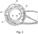
- the stator 15 comprises a support piece 60, represented more particularly in FIG. figure 2 , injected thermoplastic material, which maintains at least one temperature sensor 80 of the stator.
- the support piece 60 comprises a radially outer tubular skirt 91 and a radially inner skirt 92, concentric with an X axis, interconnected by an intermediate wall 93 extending perpendicularly to the axis X.
- the intermediate wall 93 has openings 94.
- a tab 95 for holding the sensor 80 is molded with the intermediate wall 93.
- the stator 15 comprises unrepresented coils and end insulators.
- the inner skirt 92 is placed behind these end insulators, while the outer skirt 91 faces the radially inner surface of the casing 14.
- a resin 96 coats the stator winding and the support piece 60, in favor of the openings. 94 of this one.
- the nut 30 has blind holes 50 at its rear end.
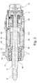
- the variant of the figure 3 differs from that of figure 1 in that the nut 30 no longer carries the magnets 25, these being carried by a hub 110 attached to the shaft 2.
- the threaded portion 32 extends between the second front bearing 4 and the stator 15.
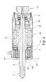
- the nut 30 is located at the front of the engine, at an opening 116 of the front flange 10.
- the threaded portion 32 extends forward of the front bearing 4, in the opening 116.
- the magnets 25 are worn directly by the tree 2.
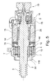
- the variant of the figure 5 differs from that of figure 4 in that the front flange 10 extends forwardly beyond the nut 30 and in that the brake is no longer carried by the casing 14 but by the rear flange 18.
- front bearing or bearings may be other than those described, as well as the rear bearing.
Landscapes
- Engineering & Computer Science (AREA)
- Power Engineering (AREA)
- Connection Of Motors, Electrical Generators, Mechanical Devices, And The Like (AREA)
Applications Claiming Priority (1)
| Application Number | Priority Date | Filing Date | Title |
|---|---|---|---|
| FR1356911A FR3008563B1 (fr) | 2013-07-12 | 2013-07-12 | Moteur electrique |
Publications (2)
| Publication Number | Publication Date |
|---|---|
| EP2824366A1 EP2824366A1 (fr) | 2015-01-14 |
| EP2824366B1 true EP2824366B1 (fr) | 2018-10-31 |
Family
ID=49713161
Family Applications (1)
| Application Number | Title | Priority Date | Filing Date |
|---|---|---|---|
| EP14176623.8A Active EP2824366B1 (fr) | 2013-07-12 | 2014-07-10 | Moteur électrique |
Country Status (3)
| Country | Link |
|---|---|
| EP (1) | EP2824366B1 (da) |
| DK (1) | DK2824366T3 (da) |
| FR (1) | FR3008563B1 (da) |
Family Cites Families (2)
| Publication number | Priority date | Publication date | Assignee | Title |
|---|---|---|---|---|
| US2688520A (en) * | 1950-09-11 | 1954-09-07 | Union Oil Co | Pressure seal for rotating shafts |
| EP1437819B1 (en) * | 2003-01-10 | 2008-11-05 | Askoll Holding S.r.l. | Permanent magnet synchronous electric motor for circulation pumps of heating and conditioning systems |
-
2013
- 2013-07-12 FR FR1356911A patent/FR3008563B1/fr active Active
-
2014
- 2014-07-10 EP EP14176623.8A patent/EP2824366B1/fr active Active
- 2014-07-10 DK DK14176623.8T patent/DK2824366T3/da active
Non-Patent Citations (1)
| Title |
|---|
| None * |
Also Published As
| Publication number | Publication date |
|---|---|
| EP2824366A1 (fr) | 2015-01-14 |
| FR3008563B1 (fr) | 2015-08-21 |
| DK2824366T3 (da) | 2019-02-25 |
| FR3008563A1 (fr) | 2015-01-16 |
Similar Documents
| Publication | Publication Date | Title |
|---|---|---|
| FR2932863A1 (fr) | Dispositif de poulie pour galet tendeur ou enrouleur. | |
| FR2968373A1 (fr) | Roulement pour dispositif de galet tendeur et galet tendeur associe | |
| EP3292315B1 (fr) | Ensemble electromecanique comportant une machine electrique couplee a un reducteur | |
| FR2954437A1 (fr) | Dispositif de poulie pour galet tendeur ou enrouleur. | |
| FR2729440A1 (fr) | Palier a roulement, notamment palier arriere d'alternateur de vehicule automobile | |
| FR3006711A1 (fr) | Systeme d'entrainement de pompe a eau et procede de montage | |
| EP2112402B1 (fr) | Actionneur à tige principale et tige auxiliaire | |
| FR2922605A1 (fr) | Module debrayable pour systeme de transmission d'un couple de demarrage a un moteur a combustion interne | |
| FR2915778A1 (fr) | Dispositif de palier a roulement pour colonne de direction | |
| FR2914381A1 (fr) | Dispositif de poulie debrayable. | |
| FR3037115A1 (fr) | Dispositif de poulie pour galet tendeur ou enrouleur | |
| WO2016177550A1 (fr) | Ensemble electromecanique comportant une machine electrique couplee a un reducteur | |
| EP1080317A1 (fr) | Butee de debrayage a auto-alignement par manchon | |
| EP1908980A1 (fr) | Dispositif de poulie debrayable | |
| FR3014144A1 (fr) | Unite de soupape, telle qu'une unite de clapet d'echappement pour vehicules automobiles | |
| EP2824366B1 (fr) | Moteur électrique | |
| FR2992367A1 (fr) | Dispositif de demarrage et procede de montage d'un dispositif de demarrage | |
| FR2898951A1 (fr) | Butee de debrayage auto-centreuse | |
| FR3034585A1 (fr) | Liaison entre un arbre de machine electrique et un reducteur | |
| FR2933460A1 (fr) | Dispositif de poulie debrayable | |
| EP3533133B1 (fr) | Machine avec système de blocage axial de l'arbre | |
| FR2669980A1 (fr) | Butee de debrayage a rondelle elastique externe, notamment pour vehicules automobiles. | |
| FR2938033A1 (fr) | Dispositif de poulie debrayable | |
| FR2992391A1 (fr) | Systeme d'entrainement a vis, notamment pour un frein d'immobilisation | |
| FR2939855A1 (fr) | Roue libre pour dispositif de poulie debrayable |
Legal Events
| Date | Code | Title | Description |
|---|---|---|---|
| 17P | Request for examination filed |
Effective date: 20140710 |
|
| AK | Designated contracting states |
Kind code of ref document: A1 Designated state(s): AL AT BE BG CH CY CZ DE DK EE ES FI FR GB GR HR HU IE IS IT LI LT LU LV MC MK MT NL NO PL PT RO RS SE SI SK SM TR |
|
| AX | Request for extension of the european patent |
Extension state: BA ME |
|
| PUAI | Public reference made under article 153(3) epc to a published international application that has entered the european phase |
Free format text: ORIGINAL CODE: 0009012 |
|
| R17P | Request for examination filed (corrected) |
Effective date: 20150714 |
|
| RBV | Designated contracting states (corrected) |
Designated state(s): AL AT BE BG CH CY CZ DE DK EE ES FI FR GB GR HR HU IE IS IT LI LT LU LV MC MK MT NL NO PL PT RO RS SE SI SK SM TR |
|
| GRAP | Despatch of communication of intention to grant a patent |
Free format text: ORIGINAL CODE: EPIDOSNIGR1 |
|
| STAA | Information on the status of an ep patent application or granted ep patent |
Free format text: STATUS: GRANT OF PATENT IS INTENDED |
|
| INTG | Intention to grant announced |
Effective date: 20180531 |
|
| GRAS | Grant fee paid |
Free format text: ORIGINAL CODE: EPIDOSNIGR3 |
|
| GRAA | (expected) grant |
Free format text: ORIGINAL CODE: 0009210 |
|
| STAA | Information on the status of an ep patent application or granted ep patent |
Free format text: STATUS: THE PATENT HAS BEEN GRANTED |
|
| AK | Designated contracting states |
Kind code of ref document: B1 Designated state(s): AL AT BE BG CH CY CZ DE DK EE ES FI FR GB GR HR HU IE IS IT LI LT LU LV MC MK MT NL NO PL PT RO RS SE SI SK SM TR |
|
| REG | Reference to a national code |
Ref country code: CH Ref legal event code: EP Ref country code: GB Ref legal event code: FG4D Free format text: NOT ENGLISH |
|
| REG | Reference to a national code |
Ref country code: AT Ref legal event code: REF Ref document number: 1059794 Country of ref document: AT Kind code of ref document: T Effective date: 20181115 |
|
| REG | Reference to a national code |
Ref country code: DE Ref legal event code: R096 Ref document number: 602014034986 Country of ref document: DE |
|
| REG | Reference to a national code |
Ref country code: IE Ref legal event code: FG4D Free format text: LANGUAGE OF EP DOCUMENT: FRENCH |
|
| REG | Reference to a national code |
Ref country code: DK Ref legal event code: T3 Effective date: 20190219 |
|
| REG | Reference to a national code |
Ref country code: SE Ref legal event code: TRGR |
|
| REG | Reference to a national code |
Ref country code: NL Ref legal event code: MP Effective date: 20181031 |
|
| REG | Reference to a national code |
Ref country code: LT Ref legal event code: MG4D |
|
| REG | Reference to a national code |
Ref country code: AT Ref legal event code: MK05 Ref document number: 1059794 Country of ref document: AT Kind code of ref document: T Effective date: 20181031 |
|
| PG25 | Lapsed in a contracting state [announced via postgrant information from national office to epo] |
Ref country code: ES Free format text: LAPSE BECAUSE OF FAILURE TO SUBMIT A TRANSLATION OF THE DESCRIPTION OR TO PAY THE FEE WITHIN THE PRESCRIBED TIME-LIMIT Effective date: 20181031 Ref country code: IS Free format text: LAPSE BECAUSE OF FAILURE TO SUBMIT A TRANSLATION OF THE DESCRIPTION OR TO PAY THE FEE WITHIN THE PRESCRIBED TIME-LIMIT Effective date: 20190228 Ref country code: AT Free format text: LAPSE BECAUSE OF FAILURE TO SUBMIT A TRANSLATION OF THE DESCRIPTION OR TO PAY THE FEE WITHIN THE PRESCRIBED TIME-LIMIT Effective date: 20181031 Ref country code: NO Free format text: LAPSE BECAUSE OF FAILURE TO SUBMIT A TRANSLATION OF THE DESCRIPTION OR TO PAY THE FEE WITHIN THE PRESCRIBED TIME-LIMIT Effective date: 20190131 Ref country code: BG Free format text: LAPSE BECAUSE OF FAILURE TO SUBMIT A TRANSLATION OF THE DESCRIPTION OR TO PAY THE FEE WITHIN THE PRESCRIBED TIME-LIMIT Effective date: 20190131 Ref country code: LT Free format text: LAPSE BECAUSE OF FAILURE TO SUBMIT A TRANSLATION OF THE DESCRIPTION OR TO PAY THE FEE WITHIN THE PRESCRIBED TIME-LIMIT Effective date: 20181031 Ref country code: FI Free format text: LAPSE BECAUSE OF FAILURE TO SUBMIT A TRANSLATION OF THE DESCRIPTION OR TO PAY THE FEE WITHIN THE PRESCRIBED TIME-LIMIT Effective date: 20181031 Ref country code: HR Free format text: LAPSE BECAUSE OF FAILURE TO SUBMIT A TRANSLATION OF THE DESCRIPTION OR TO PAY THE FEE WITHIN THE PRESCRIBED TIME-LIMIT Effective date: 20181031 Ref country code: PL Free format text: LAPSE BECAUSE OF FAILURE TO SUBMIT A TRANSLATION OF THE DESCRIPTION OR TO PAY THE FEE WITHIN THE PRESCRIBED TIME-LIMIT Effective date: 20181031 Ref country code: LV Free format text: LAPSE BECAUSE OF FAILURE TO SUBMIT A TRANSLATION OF THE DESCRIPTION OR TO PAY THE FEE WITHIN THE PRESCRIBED TIME-LIMIT Effective date: 20181031 |
|
| PG25 | Lapsed in a contracting state [announced via postgrant information from national office to epo] |
Ref country code: NL Free format text: LAPSE BECAUSE OF FAILURE TO SUBMIT A TRANSLATION OF THE DESCRIPTION OR TO PAY THE FEE WITHIN THE PRESCRIBED TIME-LIMIT Effective date: 20181031 Ref country code: RS Free format text: LAPSE BECAUSE OF FAILURE TO SUBMIT A TRANSLATION OF THE DESCRIPTION OR TO PAY THE FEE WITHIN THE PRESCRIBED TIME-LIMIT Effective date: 20181031 Ref country code: AL Free format text: LAPSE BECAUSE OF FAILURE TO SUBMIT A TRANSLATION OF THE DESCRIPTION OR TO PAY THE FEE WITHIN THE PRESCRIBED TIME-LIMIT Effective date: 20181031 Ref country code: GR Free format text: LAPSE BECAUSE OF FAILURE TO SUBMIT A TRANSLATION OF THE DESCRIPTION OR TO PAY THE FEE WITHIN THE PRESCRIBED TIME-LIMIT Effective date: 20190201 Ref country code: PT Free format text: LAPSE BECAUSE OF FAILURE TO SUBMIT A TRANSLATION OF THE DESCRIPTION OR TO PAY THE FEE WITHIN THE PRESCRIBED TIME-LIMIT Effective date: 20190301 |
|
| PG25 | Lapsed in a contracting state [announced via postgrant information from national office to epo] |
Ref country code: CZ Free format text: LAPSE BECAUSE OF FAILURE TO SUBMIT A TRANSLATION OF THE DESCRIPTION OR TO PAY THE FEE WITHIN THE PRESCRIBED TIME-LIMIT Effective date: 20181031 |
|
| REG | Reference to a national code |
Ref country code: DE Ref legal event code: R097 Ref document number: 602014034986 Country of ref document: DE |
|
| PG25 | Lapsed in a contracting state [announced via postgrant information from national office to epo] |
Ref country code: SK Free format text: LAPSE BECAUSE OF FAILURE TO SUBMIT A TRANSLATION OF THE DESCRIPTION OR TO PAY THE FEE WITHIN THE PRESCRIBED TIME-LIMIT Effective date: 20181031 Ref country code: SM Free format text: LAPSE BECAUSE OF FAILURE TO SUBMIT A TRANSLATION OF THE DESCRIPTION OR TO PAY THE FEE WITHIN THE PRESCRIBED TIME-LIMIT Effective date: 20181031 Ref country code: EE Free format text: LAPSE BECAUSE OF FAILURE TO SUBMIT A TRANSLATION OF THE DESCRIPTION OR TO PAY THE FEE WITHIN THE PRESCRIBED TIME-LIMIT Effective date: 20181031 Ref country code: RO Free format text: LAPSE BECAUSE OF FAILURE TO SUBMIT A TRANSLATION OF THE DESCRIPTION OR TO PAY THE FEE WITHIN THE PRESCRIBED TIME-LIMIT Effective date: 20181031 |
|
| PLBE | No opposition filed within time limit |
Free format text: ORIGINAL CODE: 0009261 |
|
| STAA | Information on the status of an ep patent application or granted ep patent |
Free format text: STATUS: NO OPPOSITION FILED WITHIN TIME LIMIT |
|
| 26N | No opposition filed |
Effective date: 20190801 |
|
| PG25 | Lapsed in a contracting state [announced via postgrant information from national office to epo] |
Ref country code: SI Free format text: LAPSE BECAUSE OF FAILURE TO SUBMIT A TRANSLATION OF THE DESCRIPTION OR TO PAY THE FEE WITHIN THE PRESCRIBED TIME-LIMIT Effective date: 20181031 |
|
| PG25 | Lapsed in a contracting state [announced via postgrant information from national office to epo] |
Ref country code: MC Free format text: LAPSE BECAUSE OF FAILURE TO SUBMIT A TRANSLATION OF THE DESCRIPTION OR TO PAY THE FEE WITHIN THE PRESCRIBED TIME-LIMIT Effective date: 20181031 |
|
| REG | Reference to a national code |
Ref country code: CH Ref legal event code: PL |
|
| GBPC | Gb: european patent ceased through non-payment of renewal fee |
Effective date: 20190710 |
|
| PG25 | Lapsed in a contracting state [announced via postgrant information from national office to epo] |
Ref country code: TR Free format text: LAPSE BECAUSE OF FAILURE TO SUBMIT A TRANSLATION OF THE DESCRIPTION OR TO PAY THE FEE WITHIN THE PRESCRIBED TIME-LIMIT Effective date: 20181031 |
|
| REG | Reference to a national code |
Ref country code: BE Ref legal event code: MM Effective date: 20190731 |
|
| PG25 | Lapsed in a contracting state [announced via postgrant information from national office to epo] |
Ref country code: GB Free format text: LAPSE BECAUSE OF NON-PAYMENT OF DUE FEES Effective date: 20190710 |
|
| PG25 | Lapsed in a contracting state [announced via postgrant information from national office to epo] |
Ref country code: BE Free format text: LAPSE BECAUSE OF NON-PAYMENT OF DUE FEES Effective date: 20190731 Ref country code: LU Free format text: LAPSE BECAUSE OF NON-PAYMENT OF DUE FEES Effective date: 20190710 Ref country code: CH Free format text: LAPSE BECAUSE OF NON-PAYMENT OF DUE FEES Effective date: 20190731 Ref country code: LI Free format text: LAPSE BECAUSE OF NON-PAYMENT OF DUE FEES Effective date: 20190731 |
|
| PG25 | Lapsed in a contracting state [announced via postgrant information from national office to epo] |
Ref country code: IE Free format text: LAPSE BECAUSE OF NON-PAYMENT OF DUE FEES Effective date: 20190710 |
|
| PG25 | Lapsed in a contracting state [announced via postgrant information from national office to epo] |
Ref country code: CY Free format text: LAPSE BECAUSE OF FAILURE TO SUBMIT A TRANSLATION OF THE DESCRIPTION OR TO PAY THE FEE WITHIN THE PRESCRIBED TIME-LIMIT Effective date: 20181031 |
|
| PG25 | Lapsed in a contracting state [announced via postgrant information from national office to epo] |
Ref country code: MT Free format text: LAPSE BECAUSE OF FAILURE TO SUBMIT A TRANSLATION OF THE DESCRIPTION OR TO PAY THE FEE WITHIN THE PRESCRIBED TIME-LIMIT Effective date: 20181031 Ref country code: HU Free format text: LAPSE BECAUSE OF FAILURE TO SUBMIT A TRANSLATION OF THE DESCRIPTION OR TO PAY THE FEE WITHIN THE PRESCRIBED TIME-LIMIT; INVALID AB INITIO Effective date: 20140710 |
|
| PG25 | Lapsed in a contracting state [announced via postgrant information from national office to epo] |
Ref country code: MK Free format text: LAPSE BECAUSE OF FAILURE TO SUBMIT A TRANSLATION OF THE DESCRIPTION OR TO PAY THE FEE WITHIN THE PRESCRIBED TIME-LIMIT Effective date: 20181031 |
|
| PGFP | Annual fee paid to national office [announced via postgrant information from national office to epo] |
Ref country code: DK Payment date: 20220622 Year of fee payment: 9 |
|
| PGFP | Annual fee paid to national office [announced via postgrant information from national office to epo] |
Ref country code: IT Payment date: 20230620 Year of fee payment: 10 |
|
| REG | Reference to a national code |
Ref country code: DK Ref legal event code: EBP Effective date: 20230731 |
|
| PG25 | Lapsed in a contracting state [announced via postgrant information from national office to epo] |
Ref country code: DK Free format text: LAPSE BECAUSE OF NON-PAYMENT OF DUE FEES Effective date: 20230731 |
|
| PG25 | Lapsed in a contracting state [announced via postgrant information from national office to epo] |
Ref country code: DK Free format text: LAPSE BECAUSE OF NON-PAYMENT OF DUE FEES Effective date: 20230731 |
|
| PGFP | Annual fee paid to national office [announced via postgrant information from national office to epo] |
Ref country code: SE Payment date: 20240730 Year of fee payment: 11 |
|
| PG25 | Lapsed in a contracting state [announced via postgrant information from national office to epo] |
Ref country code: IT Free format text: LAPSE BECAUSE OF NON-PAYMENT OF DUE FEES Effective date: 20240710 |
|
| PGFP | Annual fee paid to national office [announced via postgrant information from national office to epo] |
Ref country code: DE Payment date: 20250722 Year of fee payment: 12 |
|
| PGFP | Annual fee paid to national office [announced via postgrant information from national office to epo] |
Ref country code: FR Payment date: 20250725 Year of fee payment: 12 |