EP2824291B1 - Condenser - Google Patents
Condenser Download PDFInfo
- Publication number
- EP2824291B1 EP2824291B1 EP14174844.2A EP14174844A EP2824291B1 EP 2824291 B1 EP2824291 B1 EP 2824291B1 EP 14174844 A EP14174844 A EP 14174844A EP 2824291 B1 EP2824291 B1 EP 2824291B1
- Authority
- EP
- European Patent Office
- Prior art keywords
- plate
- body part
- condenser
- turbine
- steam
- Prior art date
- Legal status (The legal status is an assumption and is not a legal conclusion. Google has not performed a legal analysis and makes no representation as to the accuracy of the status listed.)
- Active
Links
- 238000001816 cooling Methods 0.000 description 11
- 230000000694 effects Effects 0.000 description 4
- CURLTUGMZLYLDI-UHFFFAOYSA-N Carbon dioxide Chemical compound O=C=O CURLTUGMZLYLDI-UHFFFAOYSA-N 0.000 description 3
- 238000000926 separation method Methods 0.000 description 3
- 238000011144 upstream manufacturing Methods 0.000 description 3
- XLYOFNOQVPJJNP-UHFFFAOYSA-N water Substances O XLYOFNOQVPJJNP-UHFFFAOYSA-N 0.000 description 3
- 229910002092 carbon dioxide Inorganic materials 0.000 description 2
- 239000001569 carbon dioxide Substances 0.000 description 2
- 230000001154 acute effect Effects 0.000 description 1
- 230000000903 blocking effect Effects 0.000 description 1
- 239000000470 constituent Substances 0.000 description 1
- 239000002826 coolant Substances 0.000 description 1
- 239000000498 cooling water Substances 0.000 description 1
- -1 for example Substances 0.000 description 1
- 238000004519 manufacturing process Methods 0.000 description 1
- 230000004048 modification Effects 0.000 description 1
- 238000012986 modification Methods 0.000 description 1
- 238000006467 substitution reaction Methods 0.000 description 1
Images


Classifications
-
- F—MECHANICAL ENGINEERING; LIGHTING; HEATING; WEAPONS; BLASTING
- F01—MACHINES OR ENGINES IN GENERAL; ENGINE PLANTS IN GENERAL; STEAM ENGINES
- F01K—STEAM ENGINE PLANTS; STEAM ACCUMULATORS; ENGINE PLANTS NOT OTHERWISE PROVIDED FOR; ENGINES USING SPECIAL WORKING FLUIDS OR CYCLES
- F01K11/00—Plants characterised by the engines being structurally combined with boilers or condensers
-
- F—MECHANICAL ENGINEERING; LIGHTING; HEATING; WEAPONS; BLASTING
- F01—MACHINES OR ENGINES IN GENERAL; ENGINE PLANTS IN GENERAL; STEAM ENGINES
- F01K—STEAM ENGINE PLANTS; STEAM ACCUMULATORS; ENGINE PLANTS NOT OTHERWISE PROVIDED FOR; ENGINES USING SPECIAL WORKING FLUIDS OR CYCLES
- F01K9/00—Plants characterised by condensers arranged or modified to co-operate with the engines
- F01K9/003—Plants characterised by condensers arranged or modified to co-operate with the engines condenser cooling circuits
-
- F—MECHANICAL ENGINEERING; LIGHTING; HEATING; WEAPONS; BLASTING
- F01—MACHINES OR ENGINES IN GENERAL; ENGINE PLANTS IN GENERAL; STEAM ENGINES
- F01K—STEAM ENGINE PLANTS; STEAM ACCUMULATORS; ENGINE PLANTS NOT OTHERWISE PROVIDED FOR; ENGINES USING SPECIAL WORKING FLUIDS OR CYCLES
- F01K11/00—Plants characterised by the engines being structurally combined with boilers or condensers
- F01K11/02—Plants characterised by the engines being structurally combined with boilers or condensers the engines being turbines
-
- F—MECHANICAL ENGINEERING; LIGHTING; HEATING; WEAPONS; BLASTING
- F01—MACHINES OR ENGINES IN GENERAL; ENGINE PLANTS IN GENERAL; STEAM ENGINES
- F01K—STEAM ENGINE PLANTS; STEAM ACCUMULATORS; ENGINE PLANTS NOT OTHERWISE PROVIDED FOR; ENGINES USING SPECIAL WORKING FLUIDS OR CYCLES
- F01K9/00—Plants characterised by condensers arranged or modified to co-operate with the engines
- F01K9/02—Arrangements or modifications of condensate or air pumps
-
- F—MECHANICAL ENGINEERING; LIGHTING; HEATING; WEAPONS; BLASTING
- F28—HEAT EXCHANGE IN GENERAL
- F28B—STEAM OR VAPOUR CONDENSERS
- F28B1/00—Condensers in which the steam or vapour is separate from the cooling medium by walls, e.g. surface condenser
-
- F—MECHANICAL ENGINEERING; LIGHTING; HEATING; WEAPONS; BLASTING
- F28—HEAT EXCHANGE IN GENERAL
- F28B—STEAM OR VAPOUR CONDENSERS
- F28B1/00—Condensers in which the steam or vapour is separate from the cooling medium by walls, e.g. surface condenser
- F28B1/06—Condensers in which the steam or vapour is separate from the cooling medium by walls, e.g. surface condenser using air or other gas as the cooling medium
-
- F—MECHANICAL ENGINEERING; LIGHTING; HEATING; WEAPONS; BLASTING
- F01—MACHINES OR ENGINES IN GENERAL; ENGINE PLANTS IN GENERAL; STEAM ENGINES
- F01D—NON-POSITIVE DISPLACEMENT MACHINES OR ENGINES, e.g. STEAM TURBINES
- F01D25/00—Component parts, details, or accessories, not provided for in, or of interest apart from, other groups
- F01D25/30—Exhaust heads, chambers, or the like
Definitions
- Embodiments described herein relate generally to a condenser.
- Improvement in thermal efficiency of a steam turbine used in a thermal power station and the like has become an important task leading to efficient use of energy resources and a reduction in carbon dioxide (CO 2 ) emission. Effectively converting given energy to mechanical work makes it possible to achieve the improvement in thermal efficiency of a steam turbine. To achieve this, reducing various internal losses is required.
- the internal losses of the steam turbine includes a profile loss ascribable to a blade shape, turbine cascade losses based on a secondary flow loss of steam, a leakage loss of steam, a moisture loss of steam, and so on, passage part losses in passages other than a cascade, represented by a steam valve and a crossover pipe, turbine exhaust losses ascribable a turbine exhaust chamber, condenser internal losses occurring inside a condenser, and so on.
- the condenser internal loss out of these losses is classified into a pressure loss occurring in a connecting body part connecting the exhaust chamber of the steam turbine and a condenser main body part and a pressure loss occurring in the condenser main body part.
- the condenser main body part provides under the connecting body part and has a cooling pipe bundle group to condense steam.
- Document WO. 99/51858 discloses such a condenser.
- the pressure loss in the connecting body part is a pressure loss in the steam flowing into the connecting body part.
- This pressure loss greatly depends on the shape of the connecting body part and the disposition of structures such as pipes.
- the pressure loss increases in proportion to the square of a flow velocity of the steam. Therefore, it is effective to reduce the flow velocity of the steam by increasing the size of the connecting body part in an allowable range.
- the increase of the size of the connecting body part is restricted by manufacturing cost, arrangement space of a building, and so on.
- the connecting body part has a diffuser shape whose passage sectional area increases from its inlet toward its outlet.
- structural strength members are installed inside the connecting body part in addition to pipes such as neck heater pipes and turbine bypass pipes.
- the area and shape of the outlet are decided based on the arrangement structure of the cooling pipe bundle group which is required in the condenser main body part. Therefore, a spreading angle of spreading sidewalls of the connecting body part having the diffuser shape is decided by the required area and shape of the outlet of the connecting body part. Note that the spreading angle of the spreading sidewalls is an angle made by a vertical direction and an inner surface of each of the spreading sidewalls.
- a condenser disposed under a steam turbine including an exhaust chamber of a downward exhaust type.
- the condenser includes: a condenser main body part which is disposed under the steam turbine to condense steam; and a connecting body part connecting the exhaust chamber and the condenser main body part and having a pair of lateral sidewalls which face each other in a direction perpendicular to a turbine rotor axial direction of the steam turbine and whose inner wall surfaces are inclined more outward in terms of the perpendicular direction as the inner wall surfaces go more downstream.
- the condenser further includes a pair of plate-shaped members which are provided on an inner wall surface of at least one of longitudinal sidewalls facing each other in the turbine rotor axial direction and adjacent to the lateral sidewalls, the plate-shaped members being located across a position of an inlet of the connecting body part and on more outer sides than the position of the inlet in terms of the perpendicular direction, projecting in the turbine rotor axial direction, and extending downstream.
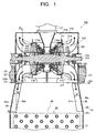
- Fig. 1 is a view illustrating a meridian cross section in a vertical direction of a steam turbine 100 including a condenser 10 of a first embodiment
- Fig. 2 is a view illustrating a cross section taken along A-A line in Fig. 1 .
- a low-pressure turbine of a double-flow exhaust type including exhaust chambers of a downward exhaust type is taken as an example of the steam turbine 100.
- the flows of steam are indicated by the arrows.
- the illustration of pipes such as neck heater pipes and turbine bypass pipes and structural strength members provided in a connecting body part 30 is omitted.
- the condenser 10 is disposed under the steam turbine 100.
- the structure of the steam turbine 100 will be first described.
- An inner casing 111 is provided in an outer casing 110 of the steam turbine 100.
- a turbine rotor 113 implanted rotor blades 112 is penetratingly disposed.
- the plural rotor blades 112 are implanted in a circumferential direction to form a rotor blade cascade.
- a plurality of stages of the rotor blade cascades are provided in a turbine rotor axial direction.
- the turbine rotor 113 is supported rotatably by a rotor bearing 114.
- stationary blades 116 supported by diaphragms 115a, 115b are disposed alternately with the rotor blades 112 in the turbine rotor axial direction.
- the plural stationary blades 116 are supported in the circumferential direction to form a stationary blade cascade.
- the stationary blade cascade and the rotor blade cascade located on an immediately downstream side of the stationary blade cascade form one turbine stage.
- an intake chamber 118 into which the steam from a crossover pipe 117 is led is provided. From this intake chamber 118, the steam is distributed and led to the left and right turbine stages.
- an annular diffuser 121 is formed by a steam guide 119 on an outer circumferential side and a bearing cone 120 on an inner circumferential side thereof.
- the annular diffuser 121 discharges the steam radially outward.
- the steam turbine 100 includes the exhaust chambers 122 of the downward exhaust type having the annular diffuser 121.
- the condenser 10 includes a condenser main body part 20 and the connecting body part 30 as illustrated in Fig. 1 .
- the condenser main body part 20 is disposed under the steam turbine 100 to condense the steam by cooling.
- the condenser main body part 20 is connected to the exhaust chambers 122 of the steam turbine 100 via the connecting body part 30.
- a plurality of cooling pipes 21 are disposed to form a cooling pipe bundle group 22 as illustrated in Fig. 1 .
- a cooling medium such as, for example, cooling water flows in the cooling pipes 211.
- the steam flowing into the condenser main body part 20 via the connecting body part 30 is condensed by coming into contact with the cooling pipes 21, to become condensed water.
- the connecting body part 30 has a pair of lateral sidewalls 31, 32 facing each other in a direction (hereinafter referred to as an axis perpendicular direction) perpendicular to a turbine rotor axial direction of the steam turbine 100 as illustrated in Fig. 2 .
- Inner wall surfaces 31 a, 32a of the lateral sidewalls 31, 32 are inclined more outward in terms of the axis perpendicular direction as they go more downstream.
- the lateral sidewall 31 is inclined leftward from an inlet 33 of the connecting body part 30, and the lateral sidewall 32 is inclined rightward from the inlet 33 of the connecting body part 30.
- an angle ⁇ made by the vertical direction and each of the inner wall surfaces 31a, 32a is decided by, for example, a set passage sectional area of an outlet 34 of the connecting body part 30. Then, the passage sectional area of the outlet 34 of the connecting body part 30 is decided by, for example, the specifications of the cooling pipe bundle group 22 in the condenser main body part 20 and so on.
- the connecting body part 30 has a pair of longitudinal sidewalls 35, 36 facing each other in the turbine rotor axial direction and adjacent to the lateral sidewalls 31, 32.
- Inner wall surfaces 35a, 36a of the longitudinal sidewalls 35, 36 are inclined more outward in terms of the turbine rotor axial direction as they go more downstream, for instance.
- the longitudinal sidewall 35 is inclined leftward from the inlet 33 of the connecting body part 30, and the longitudinal sidewall 36 is inclined rightward from the inlet 33 of the connecting body part 30.
- the structure of the longitudinal sidewalls 35,36 is not limited to such an inclined structure, and for example, they may be formed to extend in the vertical direction.
- the structure of the longitudinal sidewalls 35, 36 is decided by, for example, the specifications of the cooling pipe bundle group 22 in the condenser main body part 20 and so on.
- the connecting body part 30 forms a steam passage in a diffuser shape whose passage cross section continuously increases as it goes more downstream.
- the connecting body part 30 is formed in a diffuser shape whose passage cross section perpendicular to a flow direction of the steam has a quadrangular shape as illustrated in Fig. 1 and Fig. 2 , for instance.
- a pair of plate-shaped members 40a, 40b projecting in the turbine rotor axial direction and extending downstream are provided as illustrated in Fig. 1 and Fig. 2 .
- a pair of plate-shaped members 41a, 41b projecting in the turbine rotor axial direction and extending downstream are provided as illustrated in Fig. 1 .
- the pair of plate-shaped member 40a and plate-shaped member 40b are provided across a position of the inlet 33 of the connecting body part 30, on more outer sides than the position of the inlet 33 in terms of the axis perpendicular direction.
- the plate-shaped member 40a is provided on the inner wall surface 35a of the longitudinal sidewall 35 so as to be located more leftward than the inlet 33
- the plate-shaped member 40b is provided on the inner wall surface 35a of the longitudinal sidewall 35 so as to be located more rightward than the inlet 33.
- the pair of plate-shaped member 41a and plate-shaped member 41 b are provided across the position of the inlet 33 of the connecting body part 30, on more outer sides than the position of the inlet 33 in terms of the axis perpendicular direction.
- the plate-shaped members 40a, 40b are provided so as to extend in the vertical direction in the cross section perpendicular to the turbine rotor axial direction as illustrated in Fig. 2 .
- a distance L between the plate-shaped member 40a and the plate-shaped member 40b is preferably set so that, for example, L/X falls within a range of 1.1 to 1.7, where X is a width of the inlet 33 of the connecting body part 30 in the axis perpendicular direction.
- L/X is preferably within this range. Consequently, it is possible to prevent the separation of the flow along the lateral sidewalls 31, 32. Note that this description regarding the plate-shaped members 41a, 41b also applies to the plate-shaped members 40a, 40b.
- a projection width W of each of the plate-shaped members 40a, 40b, 41 a, 41b in the turbine rotor axial direction is set constant as illustrated in Fig. 1 , for instance.
- the projection width W is a width in a direction perpendicular to the inner wall surfaces 35a, 36a in Fig. 1 .
- the projection width W is preferably equal to or smaller than an outlet width Y of the annular diffuser 121 in the turbine rotor axial direction.
- the outlet width Y is a distance between the endmost portion 119a and the endmost portion 120a.
- the outlet width Y is the shortest distance from the outlet-side endmost portion 119a of the steam guide 119 to the bearing cone 120.
- a reason why the projection width W is preferably within this range here is that it is possible to lead the steam flowing out from the annular diffuser 121 to areas between the plate-shaped member 40a and the plate-shaped member 40b and between the plate-shaped member 41a and the plate-shaped member 41b, to lead the steam to the condenser main body part 20 without excessively blocking the flow of the steam.
- the plate-shaped members 40a, 40b, 41a, 41b each have, for example, a constant thickness t.
- the plate-shaped members 40a, 40b, 41 a, 41b are preferably provided, for example, up to a boundary of the connecting body part 30 and the condenser main body part 20 as illustrated in Fig. 1 and Fig. 2 .
- the plate-shaped members 40a, 40b, 41 a, 41b are provided on the longitudinal sidewalls 35, 36 on the sides where the outlets of the exhaust chambers 122 are provided. Since the low-pressure turbine of the double-flow exhaust type is illustrated as the steam turbine 100 here, the exhaust chambers 122 exist at two places in the turbine rotor axial direction respectively. Therefore, the plate-shaped members 40a, 40b and the plate-shaped members 41a, 41 b are provided on the longitudinal sidewall 35 and the longitudinal sidewall 36 respectively.
- the plate-shaped members are provided only on the longitudinal sidewall on the side where the outlet of the exhaust chamber 122 is provided.
- the steam discharged from an upper half of the annular diffuser 121 flows into the exhaust chambers 122, with its flow direction changed downward, while spreading also in the turbine rotor axial direction.
- the steam flowing into the connecting body part 30 from the exhaust chambers 122 flows downstream to flow into the condenser main body part 20.
- the steam flowing out from a lower half of the annular diffuser 121 to the exhaust chambers 122 to flow into the connecting body part 30 flows along the longitudinal sidewall 35 in the connecting body part 30 while spreading toward the lateral sidewalls 31, 32, that is, in the axis perpendicular direction.
- the steam flowing out into the connecting body part 30 is restricted in its spread in the axis perpendicular direction by the plate-shaped members 40a, 40b in the cross section illustrated in Fig. 2 and flows between the plate-shaped member 40a and the plate-shaped member 40b toward the downstream condenser main body part 20.
- the steam flowing out into the connecting body part 30 flows between the plate-shaped member 40a and the plate-shaped member 40b toward the downstream condenser main body part 20 without influenced by the inclination of the lateral sidewalls 31, 32.
- the steam flowing out from the lower half of the annular diffuser 121 to the exhaust chambers 122 to flow out into the connecting body part 30 does not flow along the lateral sidewalls 31, 32 which are on more outer sides than the plate-shaped members 40a, 40b in terms of the axis perpendicular direction.
- the steam flowing into the condenser main body part 20 comes into contact with the cooling pipes 21 to be condensed by cooling, thereby becoming condensed water.
- the condensed water is stored in, for example, a bottom portion of the condenser main body part 20 and is led to a boiler and so on again by a feed pump or the like.
- providing the plate-shaped members 40a, 40b, 41 a, 41 b causes the steam to flow into the condenser main body part 20 without separating in the connecting body part 30. This can reduce the pressure loss in the connecting body part 30.
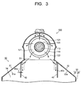
- Fig. 3 is a view illustrating a cross section corresponding to the cross section taken along A-A line in Fig. 1 , of the steam turbine 100 including the condenser 10 of the first embodiment having plate-shaped members 40a, 40b in another shape. Note that, though the structure of the plate-shaped members 40a, 40b is described here, the structure of the plate-shaped members 41a, 41b is also the same.
- a thickness t of the plate-shaped members 40a, 40b may become gradually smaller as they go more downstream.
- facing surfaces 42, 43 of the plate-shaped member 40a and the plate-shaped member 40b may be inclined surfaces inclined more outward in terms of the axis perpendicular direction as they go more downstream.
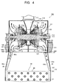
- Fig. 4 is a view illustrating a meridian cross section in the vertical direction of the steam turbine 100 including the condenser 10 of the first embodiment having plate-shaped members 40a, 40b, 41 a, 41b in another shape.
- a projection width W of each of the plate-shaped members 40a, 40b, 41a, 41b may become narrower as it goes more downstream.
- the projection width W of an exhaust chamber-side end portion of each of the plate-shaped members 40a, 40b, 41a, 41b is preferably equal to or smaller than the outlet width Y of the annular diffuser 21.
- the plate-shaped members 40a, 40b, 41a, 41b have such a structure, on the upstream side in the connecting body part 30, it is possible to lead the steam flowing out from the annular diffuser 121 to areas between the plate-shaped member 40a and the plate-shaped member 40b and between the plate-shaped member 41a and the plate-shaped member 41 b, and at the same time, on the downstream side, it is possible to reduce the contact area between the steam and the plate-shaped members 40a, 40b, 41 a, 41 b. This can further reduce the pressure loss of the steam flowing between the plate-shaped member 40a and the plate-shaped member 40b and between the plate-shaped member 41a and the plate-shaped member 41b.
- Fig. 5 is a view illustrating a cross section corresponding to the cross section taken along A-A line in Fig. 1 , of a steam turbine 100 including a condenser 10 of a second embodiment.
- Constituent parts having the same structures as those of the condenser 10 of the first embodiment will be denoted by the same reference signs, and redundant description thereof will be omitted or simplified.
- the condenser 10 of the second embodiment has the same structure as the structure of the condenser 10 of the first embodiment except the arrangement structure of plate-shaped members 40a, 40b. Therefore, the arrangement structure of the plate-shaped members 40a, 40b will be mainly described here. Note that the structure of plate-shaped members 41a, 41b is also the same as the structure of the plate-shaped members 40a, 40b.
- the plate-shaped members 40a, 40b are provided, being inclined toward lateral sidewalls 31, 32 in a cross section perpendicular to a turbine rotor axial direction.
- the plate-shaped member 40a is provided, being inclined toward the lateral sidewall 31, that is, outward in terms of an axis perpendicular direction.
- the plate-shaped member 40b is provided, being inclined toward the lateral sidewall 32, that is, outward in terms of the axis perpendicular direction.
- an angle ⁇ made by each of the plate-shaped members 40a, 40b and a vertical direction is set to an angle smaller than an angle which causes the flow of steam along their surfaces separates between the plate-shaped member 40a and the plate-shaped member 40b.
- the angle ⁇ is an acute angle out of angles made by each of the plate-shaped member 40a, 40b and the vertical direction.
- the distance L between the plate-shaped member 40a and the plate-shaped member 40b illustrated in Fig. 2 becomes a distance between an upstream end portion of the plate-shaped member 40a and an upstream end portion of the plate-shaped member 40b as illustrated in Fig. 5 .
- the condenser 10 of the second embodiment by providing the plate-shaped members 40a, 40b, 41 a, 41 b, it is possible to prevent the separation of the flow of the steam in the connecting body part 30 to reduce the pressure loss. Further, by inclining the plate-shaped members 40a, 40b, it is possible to further reduce the pressure loss in the connecting body part 30.
- the low-pressure turbine of the double-flow exhaust type including the exhaust chambers of the downward exhaust type is taken as an example of the steam turbine 100, but the steam turbine 100 is not limited to this.
- the steam turbine 100 may be any, provided that it includes the exhaust chamber of the downward exhaust type, and may have an exhaust chamber of, for example, a single-flow exhaust type.
Landscapes
- Engineering & Computer Science (AREA)
- Mechanical Engineering (AREA)
- General Engineering & Computer Science (AREA)
- Chemical & Material Sciences (AREA)
- Combustion & Propulsion (AREA)
- Engine Equipment That Uses Special Cycles (AREA)
- Turbine Rotor Nozzle Sealing (AREA)
Description
- Embodiments described herein relate generally to a condenser.
- Improvement in thermal efficiency of a steam turbine used in a thermal power station and the like has become an important task leading to efficient use of energy resources and a reduction in carbon dioxide (CO2) emission. Effectively converting given energy to mechanical work makes it possible to achieve the improvement in thermal efficiency of a steam turbine. To achieve this, reducing various internal losses is required.
- The internal losses of the steam turbine includes a profile loss ascribable to a blade shape, turbine cascade losses based on a secondary flow loss of steam, a leakage loss of steam, a moisture loss of steam, and so on, passage part losses in passages other than a cascade, represented by a steam valve and a crossover pipe, turbine exhaust losses ascribable a turbine exhaust chamber, condenser internal losses occurring inside a condenser, and so on.
- In a steam turbine including a turbine exhaust chamber of a downward exhaust type, the condenser internal loss out of these losses is classified into a pressure loss occurring in a connecting body part connecting the exhaust chamber of the steam turbine and a condenser main body part and a pressure loss occurring in the condenser main body part. Incidentally, the condenser main body part provides under the connecting body part and has a cooling pipe bundle group to condense steam. Document
WO. 99/51858 - The pressure loss in the connecting body part is a pressure loss in the steam flowing into the connecting body part. This pressure loss greatly depends on the shape of the connecting body part and the disposition of structures such as pipes. Generally, the pressure loss increases in proportion to the square of a flow velocity of the steam. Therefore, it is effective to reduce the flow velocity of the steam by increasing the size of the connecting body part in an allowable range. However, the increase of the size of the connecting body part is restricted by manufacturing cost, arrangement space of a building, and so on.
- The connecting body part has a diffuser shape whose passage sectional area increases from its inlet toward its outlet. Inside the connecting body part, structural strength members are installed in addition to pipes such as neck heater pipes and turbine bypass pipes. In order to reduce the pressure loss in such a connecting body part, various studies have been made.
- In the above-described connecting body part, the area and shape of the outlet are decided based on the arrangement structure of the cooling pipe bundle group which is required in the condenser main body part. Therefore, a spreading angle of spreading sidewalls of the connecting body part having the diffuser shape is decided by the required area and shape of the outlet of the connecting body part. Note that the spreading angle of the spreading sidewalls is an angle made by a vertical direction and an inner surface of each of the spreading sidewalls.
- When the spreading angle of each of the spreading sidewalls becomes larger than a predetermined angle and accordingly the spreading sidewalls spread greatly, the steam flowing from the exhaust chamber of the steam turbine into the connecting body part separates in a passage on the spreading sidewall sides. Consequently, a pressure loss in the steam flowing into the connecting body part increases.
-
-
Fig. 1 is a view illustrating a meridian cross section in a vertical direction of a steam turbine including a condenser of a first embodiment. -
Fig. 2 is a view illustrating a cross section taken along A-A line inFig. 1 . -
Fig. 3 is a view illustrating a cross section corresponding to the cross section taken along A-A line inFig. 1 , of a steam turbine including the condenser of the first embodiment having plate-shaped members in another shape. -
Fig. 4 is a view illustrating a meridian cross section in the vertical direction of the steam turbine including the condenser of the first embodiment having plate-shaped members in another shape. -
Fig. 5 is a view illustrating a cross section corresponding to the cross section taken along A-A inFig. 1 , of a steam turbine including a condenser of a second embodiment. - In one embodiment, there is provided a condenser disposed under a steam turbine including an exhaust chamber of a downward exhaust type. The condenser includes: a condenser main body part which is disposed under the steam turbine to condense steam; and a connecting body part connecting the exhaust chamber and the condenser main body part and having a pair of lateral sidewalls which face each other in a direction perpendicular to a turbine rotor axial direction of the steam turbine and whose inner wall surfaces are inclined more outward in terms of the perpendicular direction as the inner wall surfaces go more downstream. The condenser further includes a pair of plate-shaped members which are provided on an inner wall surface of at least one of longitudinal sidewalls facing each other in the turbine rotor axial direction and adjacent to the lateral sidewalls, the plate-shaped members being located across a position of an inlet of the connecting body part and on more outer sides than the position of the inlet in terms of the perpendicular direction, projecting in the turbine rotor axial direction, and extending downstream.
- Hereinafter, embodiments of the present invention will be described with reference to the drawings.
-
Fig. 1 is a view illustrating a meridian cross section in a vertical direction of asteam turbine 100 including acondenser 10 of a first embodimentFig. 2 is a view illustrating a cross section taken along A-A line inFig. 1 . - In the description here, a low-pressure turbine of a double-flow exhaust type including exhaust chambers of a downward exhaust type is taken as an example of the
steam turbine 100. InFig. 1 andFig. 2 , the flows of steam are indicated by the arrows. Further, inFig. 1 andFig. 2 , the illustration of pipes such as neck heater pipes and turbine bypass pipes and structural strength members provided in a connectingbody part 30 is omitted. - As illustrated in
Fig. 1 , thecondenser 10 is disposed under thesteam turbine 100. Here, the structure of thesteam turbine 100 will be first described. - An
inner casing 111 is provided in anouter casing 110 of thesteam turbine 100. In theinner casing 111, aturbine rotor 113 implantedrotor blades 112 is penetratingly disposed. Theplural rotor blades 112 are implanted in a circumferential direction to form a rotor blade cascade. A plurality of stages of the rotor blade cascades are provided in a turbine rotor axial direction. Theturbine rotor 113 is supported rotatably by a rotor bearing 114. - On an inner circumference of the
inner casing 111,stationary blades 116 supported bydiaphragms rotor blades 112 in the turbine rotor axial direction. The pluralstationary blades 116 are supported in the circumferential direction to form a stationary blade cascade. The stationary blade cascade and the rotor blade cascade located on an immediately downstream side of the stationary blade cascade form one turbine stage. - At a center of the
steam turbine 100, anintake chamber 118 into which the steam from acrossover pipe 117 is led is provided. From thisintake chamber 118, the steam is distributed and led to the left and right turbine stages. - On a downstream side of the final turbine stage, an
annular diffuser 121 is formed by asteam guide 119 on an outer circumferential side and abearing cone 120 on an inner circumferential side thereof. Theannular diffuser 121 discharges the steam radially outward. Thus, thesteam turbine 100 includes theexhaust chambers 122 of the downward exhaust type having theannular diffuser 121. - Next, the structure of the
condenser 10 will be described. - The
condenser 10 includes a condensermain body part 20 and the connectingbody part 30 as illustrated inFig. 1 . The condensermain body part 20 is disposed under thesteam turbine 100 to condense the steam by cooling. The condensermain body part 20 is connected to theexhaust chambers 122 of thesteam turbine 100 via the connectingbody part 30. - In the condenser
main body part 20, for example, a plurality ofcooling pipes 21 are disposed to form a coolingpipe bundle group 22 as illustrated inFig. 1 . For example, a cooling medium such as, for example, cooling water flows in the cooling pipes 211. The steam flowing into the condensermain body part 20 via the connectingbody part 30 is condensed by coming into contact with thecooling pipes 21, to become condensed water. - The
connecting body part 30 has a pair oflateral sidewalls steam turbine 100 as illustrated inFig. 2 .Inner wall surfaces lateral sidewalls Fig. 2 , thelateral sidewall 31 is inclined leftward from aninlet 33 of the connectingbody part 30, and thelateral sidewall 32 is inclined rightward from theinlet 33 of theconnecting body part 30. - In the cross section illustrated in
Fig. 2 , an angle θ made by the vertical direction and each of theinner wall surfaces outlet 34 of the connectingbody part 30. Then, the passage sectional area of theoutlet 34 of the connectingbody part 30 is decided by, for example, the specifications of the coolingpipe bundle group 22 in the condensermain body part 20 and so on. - Further, as illustrated in
Fig. 1 , the connectingbody part 30 has a pair oflongitudinal sidewalls lateral sidewalls Inner wall surfaces longitudinal sidewalls Fig. 1 , thelongitudinal sidewall 35 is inclined leftward from theinlet 33 of the connectingbody part 30, and thelongitudinal sidewall 36 is inclined rightward from theinlet 33 of the connectingbody part 30. - It should be noted that the structure of the
longitudinal sidewalls longitudinal sidewalls pipe bundle group 22 in the condensermain body part 20 and so on. - As described above, at least the
lateral sidewalls body part 30 forms a steam passage in a diffuser shape whose passage cross section continuously increases as it goes more downstream. The connectingbody part 30 is formed in a diffuser shape whose passage cross section perpendicular to a flow direction of the steam has a quadrangular shape as illustrated inFig. 1 andFig. 2 , for instance. - On the
inner wall surface 35a of thelongitudinal sidewall 35, a pair of plate-shapedmembers Fig. 1 andFig. 2 . Similarly to theinner wall surface 35a, on theinner wall surface 36a of thelongitudinal sidewall 36, a pair of plate-shapedmembers 41a, 41b projecting in the turbine rotor axial direction and extending downstream are provided as illustrated inFig. 1 . - As illustrated in
Fig. 2 , the pair of plate-shapedmember 40a and plate-shapedmember 40b are provided across a position of theinlet 33 of the connectingbody part 30, on more outer sides than the position of theinlet 33 in terms of the axis perpendicular direction. In other words, in the cross section illustrated inFig. 2 , the plate-shapedmember 40a is provided on theinner wall surface 35a of thelongitudinal sidewall 35 so as to be located more leftward than theinlet 33, and the plate-shapedmember 40b is provided on theinner wall surface 35a of thelongitudinal sidewall 35 so as to be located more rightward than theinlet 33. - Note that, similarly to the pair of plate-shaped
members member 41a and plate-shaped member 41 b, though their cross sectional view corresponding toFig. 2 is not illustrated, are provided across the position of theinlet 33 of the connectingbody part 30, on more outer sides than the position of theinlet 33 in terms of the axis perpendicular direction. - The plate-shaped
members Fig. 2 . InFig. 2 , a distance L between the plate-shapedmember 40a and the plate-shapedmember 40b is preferably set so that, for example, L/X falls within a range of 1.1 to 1.7, where X is a width of theinlet 33 of the connectingbody part 30 in the axis perpendicular direction. - A reason why L/X is preferably within this range is that, before the flow spreading in the axis perpendicular direction along the
longitudinal sidewall 35 separates, the spread can be restricted by the plate-shapedmembers lateral sidewalls members 41a, 41b also applies to the plate-shapedmembers - A projection width W of each of the plate-shaped
members Fig. 1 , for instance. Here, the projection width W is a width in a direction perpendicular to theinner wall surfaces Fig. 1 . The projection width W is preferably equal to or smaller than an outlet width Y of theannular diffuser 121 in the turbine rotor axial direction. - For example, as illustrated in
Fig. 1 , when an outlet-sideendmost portion 119a of thesteam guide 119 and an outlet-sideendmost portion 120a of the bearingcone 120 are on the same level, the outlet width Y is a distance between theendmost portion 119a and theendmost portion 120a. On the other hand, when the outlet-sideendmost portion 119a of thesteam guide 119 and the outlet-sideendmost portion 120a of the bearingcone 120 are not on the same level, the outlet width Y is the shortest distance from the outlet-sideendmost portion 119a of thesteam guide 119 to the bearingcone 120. - A reason why the projection width W is preferably within this range here is that it is possible to lead the steam flowing out from the
annular diffuser 121 to areas between the plate-shapedmember 40a and the plate-shapedmember 40b and between the plate-shapedmember 41a and the plate-shaped member 41b, to lead the steam to the condensermain body part 20 without excessively blocking the flow of the steam. - Incidentally, the plate-shaped
members members body part 30 and the condensermain body part 20 as illustrated inFig. 1 andFig. 2 . - The plate-shaped
members longitudinal sidewalls exhaust chambers 122 are provided. Since the low-pressure turbine of the double-flow exhaust type is illustrated as thesteam turbine 100 here, theexhaust chambers 122 exist at two places in the turbine rotor axial direction respectively. Therefore, the plate-shapedmembers members 41a, 41 b are provided on thelongitudinal sidewall 35 and thelongitudinal sidewall 36 respectively. - Incidentally, for example, when the number of the
exhaust chamber 122 is one as in a case where a low-pressure turbine of a single-flow exhaust type is used as thesteam turbine 100, the plate-shaped members are provided only on the longitudinal sidewall on the side where the outlet of theexhaust chamber 122 is provided. - Next, the flow of the steam in the
condenser 10 will be described. - Since the flow of the steam is the same on the
longitudinal sidewall 35 side and thelongitudinal sidewall 36 side, the flow on thelongitudinal sidewall 35 side will be described here. - For example, the steam discharged from an upper half of the
annular diffuser 121 flows into theexhaust chambers 122, with its flow direction changed downward, while spreading also in the turbine rotor axial direction. The steam flowing into the connectingbody part 30 from theexhaust chambers 122 flows downstream to flow into the condensermain body part 20. - On the other hand, the steam flowing out from a lower half of the
annular diffuser 121 to theexhaust chambers 122 to flow into the connectingbody part 30 flows along thelongitudinal sidewall 35 in the connectingbody part 30 while spreading toward thelateral sidewalls body part 30 is restricted in its spread in the axis perpendicular direction by the plate-shapedmembers Fig. 2 and flows between the plate-shapedmember 40a and the plate-shapedmember 40b toward the downstream condensermain body part 20. - That is, the steam flowing out into the connecting
body part 30 flows between the plate-shapedmember 40a and the plate-shapedmember 40b toward the downstream condensermain body part 20 without influenced by the inclination of thelateral sidewalls annular diffuser 121 to theexhaust chambers 122 to flow out into the connectingbody part 30 does not flow along thelateral sidewalls members - Therefore, even when the angle θ made by the vertical direction and each of the
inner wall surfaces inner wall surfaces main body part 20 without any separation of the flow being caused. - The steam flowing into the condenser
main body part 20 comes into contact with the coolingpipes 21 to be condensed by cooling, thereby becoming condensed water. The condensed water is stored in, for example, a bottom portion of the condensermain body part 20 and is led to a boiler and so on again by a feed pump or the like. - As described above, according to the
condenser 10 of the first embodiment, providing the plate-shapedmembers main body part 20 without separating in the connectingbody part 30. This can reduce the pressure loss in the connectingbody part 30. - Here, the structure of the plate-shaped
members condenser 10 of the first embodiment is not limited to the above-described structure.Fig. 3 is a view illustrating a cross section corresponding to the cross section taken along A-A line inFig. 1 , of thesteam turbine 100 including thecondenser 10 of the first embodiment having plate-shapedmembers members members 41a, 41b is also the same. - As illustrated in
Fig. 3 , a thickness t of the plate-shapedmembers surfaces member 40a and the plate-shapedmember 40b may be inclined surfaces inclined more outward in terms of the axis perpendicular direction as they go more downstream. - When the
surfaces member 40a and the plate-shapedmember 40b becomes a passage whose width increases as it goes more downstream. Consequently, a diffuser effect is obtained between the plate-shapedmember 40a and the plate-shapedmember 40b, which can further reduce the pressure loss. -
Fig. 4 is a view illustrating a meridian cross section in the vertical direction of thesteam turbine 100 including thecondenser 10 of the first embodiment having plate-shapedmembers - As illustrated in
Fig. 4 , a projection width W of each of the plate-shapedmembers members annular diffuser 21. - When the plate-shaped
members body part 30, it is possible to lead the steam flowing out from theannular diffuser 121 to areas between the plate-shapedmember 40a and the plate-shapedmember 40b and between the plate-shapedmember 41a and the plate-shaped member 41 b, and at the same time, on the downstream side, it is possible to reduce the contact area between the steam and the plate-shapedmembers member 40a and the plate-shapedmember 40b and between the plate-shapedmember 41a and the plate-shaped member 41b. -
Fig. 5 is a view illustrating a cross section corresponding to the cross section taken along A-A line inFig. 1 , of asteam turbine 100 including acondenser 10 of a second embodiment. Constituent parts having the same structures as those of thecondenser 10 of the first embodiment will be denoted by the same reference signs, and redundant description thereof will be omitted or simplified. - The
condenser 10 of the second embodiment has the same structure as the structure of thecondenser 10 of the first embodiment except the arrangement structure of plate-shapedmembers members members 41a, 41b is also the same as the structure of the plate-shapedmembers - As illustrated in
Fig. 5 , the plate-shapedmembers lateral sidewalls member 40a is provided, being inclined toward thelateral sidewall 31, that is, outward in terms of an axis perpendicular direction. Further, the plate-shapedmember 40b is provided, being inclined toward thelateral sidewall 32, that is, outward in terms of the axis perpendicular direction. - In the cross section illustrated in
Fig. 5 , an angle α made by each of the plate-shapedmembers member 40a and the plate-shapedmember 40b. Note that the angle α is an acute angle out of angles made by each of the plate-shapedmember - Here, when the plate-shaped
members member 40a and the plate-shapedmember 40b illustrated inFig. 2 becomes a distance between an upstream end portion of the plate-shapedmember 40a and an upstream end portion of the plate-shapedmember 40b as illustrated inFig. 5 . - By thus inclining the plate-shaped
members member 40a and the plate-shapedmember 40b becomes a passage whose width increases as it goes more downstream. Consequently, a diffuser effect is obtained between the plate-shapedmember 40a and the plate-shapedmember 40b, which can further reduce the pressure loss. - According to the
condenser 10 of the second embodiment, by providing the plate-shapedmembers body part 30 to reduce the pressure loss. Further, by inclining the plate-shapedmembers body part 30. - Note that the structure of the plate-shaped
members Fig. 3 andFig. 4 , which is described in the first embodiment, is also applicable to the second embodiment. Then, the same operation and effect as the operation and effect in the first embodiment can be obtained. - According to the above-described embodiments, it is possible to reduce the pressure loss in the connecting body part connecting the exhaust chambers of the steam turbine and the condenser main body part.
- In the description of the above embodiments, the low-pressure turbine of the double-flow exhaust type including the exhaust chambers of the downward exhaust type is taken as an example of the
steam turbine 100, but thesteam turbine 100 is not limited to this. Thesteam turbine 100 may be any, provided that it includes the exhaust chamber of the downward exhaust type, and may have an exhaust chamber of, for example, a single-flow exhaust type. - While certain embodiments have been described, these embodiments have been presented by way of example only, and are not intended to limit the scope of the inventions. Indeed, the novel embodiments described herein may be embodied in a variety of other forms; furthermore, various omissions, substitutions and changes in the form of the embodiments described herein may be made without departing from the scope of the inventions. The accompanying claims and their equivalents are intended to cover such forms or modifications as would fall within the scope of the inventions.
Claims (7)
- A condenser disposed under a steam turbine including an exhaust chamber of a downward exhaust type, the condenser comprises:a condenser main body part (20) which is disposed under the steam turbine to condense steam;a connecting body part (20) connecting the exhaust chamber and the condenser main body part (20) and having a pair of lateral sidewalls (31) (32) which face each other in a direction perpendicular to a turbine rotor axial direction of the steam turbine and whose inner wall surfaces are inclined more outward in terms of the perpendicular direction as the inner wall surfaces go more downstream; and characterized in that said condenser further comprises:a pair of plate-shaped members (40a)(40b) which are provided on an inner wall surface (35a)(36a) of at least one of longitudinal sidewalls (35)(36) facing each other in the turbine rotor axial direction and adjacent to the lateral sidewalls, the plate-shaped members being located across a position of an inlet of the connecting body part and on more outer sides than the position of the inlet in terms of the perpendicular direction, projecting in the turbine rotor axial direction, and extending downstream.
- The condenser according to claim 1,
wherein an outlet of the exhaust chamber is provided on at least one side out of the pair of longitudinal sidewalls, and
wherein the plate-shaped members (40a)(40b) are provided on the longitudinal sidewall on the side where the outlet of the exhaust chamber is provided. - The condenser according to claim 1 or 2,
wherein the plate-shaped members (40a)(40b) are provided to extend in a vertical direction in a cross section perpendicular to the turbine rotor axial direction. - The condenser according to claim 1 or 2,
wherein the plate-shaped members (40a)(40b) are inclined toward the lateral sidewalls in a cross section perpendicular to the turbine rotor axial direction. - The condenser according to any one of claims 1 to 4,
wherein the steam turbine includes an annular diffuser which is provided on a downstream side of a final turbine stage to lead steam passed through the final turbine stage to the exhaust chamber, and
wherein a projection width of the plate-shaped members (40a)(40b) in the turbine rotor axial direction is equal to or smaller than an outlet width of the annular diffuser in the turbine rotor axial direction. - The condenser according to any one of claims 1 to 4,
wherein the steam turbine includes an annular diffuser which is provided on a downstream side of a final turbine stage to lead steam passed through the final turbine stage to the exhaust chamber, and
wherein a projection width of an exhaust chamber-side end portion of each of the plate-shaped members (40a)(40b) in the turbine rotor axial direction is equal to or smaller than an outlet width of the annular diffuser in the turbine rotor axial direction, and the projection width becomes narrower toward a downstream side. - The condenser according to any one of claims 1 to 6,
wherein a thickness of the plate-shaped members (40a)(40b) becomes smaller toward a downstream side.
Applications Claiming Priority (1)
| Application Number | Priority Date | Filing Date | Title |
|---|---|---|---|
| JP2013134450A JP6113586B2 (en) | 2013-06-27 | 2013-06-27 | Condenser |
Publications (2)
| Publication Number | Publication Date |
|---|---|
| EP2824291A1 EP2824291A1 (en) | 2015-01-14 |
| EP2824291B1 true EP2824291B1 (en) | 2016-05-25 |
Family
ID=51162459
Family Applications (1)
| Application Number | Title | Priority Date | Filing Date |
|---|---|---|---|
| EP14174844.2A Active EP2824291B1 (en) | 2013-06-27 | 2014-06-27 | Condenser |
Country Status (4)
| Country | Link |
|---|---|
| US (1) | US9422831B2 (en) |
| EP (1) | EP2824291B1 (en) |
| JP (1) | JP6113586B2 (en) |
| KR (1) | KR101572113B1 (en) |
Families Citing this family (1)
| Publication number | Priority date | Publication date | Assignee | Title |
|---|---|---|---|---|
| CN112762725A (en) * | 2021-01-04 | 2021-05-07 | 山东电力工程咨询院有限公司 | Condenser exhaust steam extraction device and condenser system |
Family Cites Families (18)
| Publication number | Priority date | Publication date | Assignee | Title |
|---|---|---|---|---|
| DE325568C (en) * | 1916-02-04 | 1920-09-16 | Vickers Electrical Co Ltd | Exhaust housing for axially loaded steam turbines |
| US2394685A (en) * | 1943-03-29 | 1946-02-12 | Vickers Electrical Co Ltd | Turbine installation |
| JPS4116081Y1 (en) * | 1965-10-14 | 1966-07-27 | ||
| US3575392A (en) * | 1968-04-29 | 1971-04-20 | Ingersoll Rand Co | Direct contact condenser |
| DE1812487A1 (en) * | 1968-12-03 | 1970-08-13 | Siemens Ag | Housing arrangement for low pressure parts of steam turbines in fully welded multi-shell construction |
| US4287718A (en) * | 1977-11-30 | 1981-09-08 | Offshore Power Systems | Condenser vacuum load compensating system |
| US4189927A (en) * | 1978-06-27 | 1980-02-26 | Westinghouse Electric Corp. | Condenser vacuum load compensating system |
| EP1068429B1 (en) | 1998-04-06 | 2004-06-16 | Siemens Aktiengesellschaft | Steam turbine |
| JP3746614B2 (en) | 1998-07-28 | 2006-02-15 | 三菱重工業株式会社 | Low pressure steam turbine exhaust chamber |
| US6419448B1 (en) * | 2000-03-20 | 2002-07-16 | Jerzy A. Owczarek | Flow by-pass system for use in steam turbine exhaust hoods |
| JP3690973B2 (en) | 2000-08-09 | 2005-08-31 | 三菱重工業株式会社 | Steam turbine intermediate cylinder and condenser |
| JP2002195786A (en) | 2000-12-28 | 2002-07-10 | Toshiba Corp | Condenser |
| US6981455B2 (en) * | 2002-03-08 | 2006-01-03 | Lefcort Malcolm D | Two-stage wet waste gasifier and burner |
| JP2005337650A (en) * | 2004-05-31 | 2005-12-08 | Toshiba Corp | The upper body of the condenser |
| JP2007255218A (en) * | 2006-03-20 | 2007-10-04 | Toshiba Corp | Steam turbine |
| JP2009103099A (en) | 2007-10-25 | 2009-05-14 | Toshiba Corp | Steam turbine |
| US8221054B2 (en) * | 2009-05-28 | 2012-07-17 | General Electric Company | Corrugated hood for low pressure steam turbine |
| JP5642514B2 (en) * | 2010-11-19 | 2014-12-17 | 三菱重工業株式会社 | Cabin structure of low-pressure steam turbine |
-
2013
- 2013-06-27 JP JP2013134450A patent/JP6113586B2/en not_active Expired - Fee Related
-
2014
- 2014-06-24 US US14/312,969 patent/US9422831B2/en active Active
- 2014-06-25 KR KR1020140078188A patent/KR101572113B1/en not_active Expired - Fee Related
- 2014-06-27 EP EP14174844.2A patent/EP2824291B1/en active Active
Also Published As
| Publication number | Publication date |
|---|---|
| KR20150001661A (en) | 2015-01-06 |
| EP2824291A1 (en) | 2015-01-14 |
| US9422831B2 (en) | 2016-08-23 |
| JP6113586B2 (en) | 2017-04-12 |
| KR101572113B1 (en) | 2015-11-26 |
| US20150000879A1 (en) | 2015-01-01 |
| JP2015010483A (en) | 2015-01-19 |
Similar Documents
| Publication | Publication Date | Title |
|---|---|---|
| JP5606473B2 (en) | Steam turbine | |
| EP2853694B1 (en) | Steam turbine | |
| JP5606373B2 (en) | Steam turbine | |
| JP2019100342A (en) | Centrifugal compressor | |
| EP2431569A2 (en) | Steam turbine | |
| JP2015194085A (en) | Steam turbine | |
| US8690532B2 (en) | Nozzle box of axial flow turbine and axial flow turbine | |
| US10830146B2 (en) | Compressor bleed cooling system for mid-frame torque discs downstream from a compressor assembly in a gas turbine engine | |
| US9422831B2 (en) | Condenser | |
| US8870532B2 (en) | Exhaust hood diffuser | |
| US9650966B2 (en) | Gas turbine with an air bleeder tube | |
| US10550853B2 (en) | Gas turbine engine | |
| US20130022444A1 (en) | Low pressure turbine exhaust diffuser with turbulators | |
| KR20210098152A (en) | Condensing System | |
| JP7278903B2 (en) | turbine exhaust chamber | |
| JP2016217285A (en) | Steam turbine | |
| US20130174553A1 (en) | Diffuser having fluidic actuation | |
| KR20200042187A (en) | Low loss curved pipe exhaust duct | |
| US9109467B2 (en) | Exhaust system for use with a turbine and method of assembling same | |
| KR101811223B1 (en) | Steam turbine | |
| JP5802630B2 (en) | Steam turbine equipment | |
| WO2018077839A1 (en) | Gas turbine system with bleed routing arrangement | |
| JP6239908B2 (en) | Exhaust system for use in turbine and assembly method thereof | |
| JP5826706B2 (en) | Steam turbine |
Legal Events
| Date | Code | Title | Description |
|---|---|---|---|
| 17P | Request for examination filed |
Effective date: 20140627 |
|
| AK | Designated contracting states |
Kind code of ref document: A1 Designated state(s): AL AT BE BG CH CY CZ DE DK EE ES FI FR GB GR HR HU IE IS IT LI LT LU LV MC MK MT NL NO PL PT RO RS SE SI SK SM TR |
|
| AX | Request for extension of the european patent |
Extension state: BA ME |
|
| PUAI | Public reference made under article 153(3) epc to a published international application that has entered the european phase |
Free format text: ORIGINAL CODE: 0009012 |
|
| RIN1 | Information on inventor provided before grant (corrected) |
Inventor name: OHASHI, SHINICHIRO Inventor name: FUJISAWA, TAKESHI Inventor name: TSUDA, SHOTA Inventor name: SAEKI, HIROSHI Inventor name: NOGUCHI, TARO |
|
| REG | Reference to a national code |
Ref country code: DE Ref legal event code: R079 Ref document number: 602014002068 Country of ref document: DE Free format text: PREVIOUS MAIN CLASS: F01K0011020000 Ipc: F01K0009000000 |
|
| GRAP | Despatch of communication of intention to grant a patent |
Free format text: ORIGINAL CODE: EPIDOSNIGR1 |
|
| RIC1 | Information provided on ipc code assigned before grant |
Ipc: F01K 11/02 20060101ALI20151117BHEP Ipc: F01K 9/00 20060101AFI20151117BHEP Ipc: F28B 1/06 20060101ALI20151117BHEP Ipc: F01D 25/30 20060101ALI20151117BHEP |
|
| INTG | Intention to grant announced |
Effective date: 20151204 |
|
| GRAS | Grant fee paid |
Free format text: ORIGINAL CODE: EPIDOSNIGR3 |
|
| GRAA | (expected) grant |
Free format text: ORIGINAL CODE: 0009210 |
|
| AK | Designated contracting states |
Kind code of ref document: B1 Designated state(s): AL AT BE BG CH CY CZ DE DK EE ES FI FR GB GR HR HU IE IS IT LI LT LU LV MC MK MT NL NO PL PT RO RS SE SI SK SM TR |
|
| REG | Reference to a national code |
Ref country code: GB Ref legal event code: FG4D |
|
| REG | Reference to a national code |
Ref country code: CH Ref legal event code: EP |
|
| REG | Reference to a national code |
Ref country code: IE Ref legal event code: FG4D Ref country code: AT Ref legal event code: REF Ref document number: 802514 Country of ref document: AT Kind code of ref document: T Effective date: 20160615 |
|
| REG | Reference to a national code |
Ref country code: CH Ref legal event code: NV Representative=s name: MARKS AND CLERK (LUXEMBOURG) LLP, CH |
|
| REG | Reference to a national code |
Ref country code: DE Ref legal event code: R096 Ref document number: 602014002068 Country of ref document: DE |
|
| REG | Reference to a national code |
Ref country code: LT Ref legal event code: MG4D |
|
| REG | Reference to a national code |
Ref country code: NL Ref legal event code: MP Effective date: 20160525 |
|
| PG25 | Lapsed in a contracting state [announced via postgrant information from national office to epo] |
Ref country code: LT Free format text: LAPSE BECAUSE OF FAILURE TO SUBMIT A TRANSLATION OF THE DESCRIPTION OR TO PAY THE FEE WITHIN THE PRESCRIBED TIME-LIMIT Effective date: 20160525 Ref country code: NL Free format text: LAPSE BECAUSE OF FAILURE TO SUBMIT A TRANSLATION OF THE DESCRIPTION OR TO PAY THE FEE WITHIN THE PRESCRIBED TIME-LIMIT Effective date: 20160525 Ref country code: NO Free format text: LAPSE BECAUSE OF FAILURE TO SUBMIT A TRANSLATION OF THE DESCRIPTION OR TO PAY THE FEE WITHIN THE PRESCRIBED TIME-LIMIT Effective date: 20160825 Ref country code: FI Free format text: LAPSE BECAUSE OF FAILURE TO SUBMIT A TRANSLATION OF THE DESCRIPTION OR TO PAY THE FEE WITHIN THE PRESCRIBED TIME-LIMIT Effective date: 20160525 |
|
| REG | Reference to a national code |
Ref country code: AT Ref legal event code: MK05 Ref document number: 802514 Country of ref document: AT Kind code of ref document: T Effective date: 20160525 |
|
| PG25 | Lapsed in a contracting state [announced via postgrant information from national office to epo] |
Ref country code: LV Free format text: LAPSE BECAUSE OF FAILURE TO SUBMIT A TRANSLATION OF THE DESCRIPTION OR TO PAY THE FEE WITHIN THE PRESCRIBED TIME-LIMIT Effective date: 20160525 Ref country code: PT Free format text: LAPSE BECAUSE OF FAILURE TO SUBMIT A TRANSLATION OF THE DESCRIPTION OR TO PAY THE FEE WITHIN THE PRESCRIBED TIME-LIMIT Effective date: 20160926 Ref country code: GR Free format text: LAPSE BECAUSE OF FAILURE TO SUBMIT A TRANSLATION OF THE DESCRIPTION OR TO PAY THE FEE WITHIN THE PRESCRIBED TIME-LIMIT Effective date: 20160826 Ref country code: ES Free format text: LAPSE BECAUSE OF FAILURE TO SUBMIT A TRANSLATION OF THE DESCRIPTION OR TO PAY THE FEE WITHIN THE PRESCRIBED TIME-LIMIT Effective date: 20160525 Ref country code: RS Free format text: LAPSE BECAUSE OF FAILURE TO SUBMIT A TRANSLATION OF THE DESCRIPTION OR TO PAY THE FEE WITHIN THE PRESCRIBED TIME-LIMIT Effective date: 20160525 Ref country code: SE Free format text: LAPSE BECAUSE OF FAILURE TO SUBMIT A TRANSLATION OF THE DESCRIPTION OR TO PAY THE FEE WITHIN THE PRESCRIBED TIME-LIMIT Effective date: 20160525 |
|
| PG25 | Lapsed in a contracting state [announced via postgrant information from national office to epo] |
Ref country code: IT Free format text: LAPSE BECAUSE OF FAILURE TO SUBMIT A TRANSLATION OF THE DESCRIPTION OR TO PAY THE FEE WITHIN THE PRESCRIBED TIME-LIMIT Effective date: 20160525 Ref country code: BE Free format text: LAPSE BECAUSE OF NON-PAYMENT OF DUE FEES Effective date: 20160630 |
|
| PG25 | Lapsed in a contracting state [announced via postgrant information from national office to epo] |
Ref country code: DK Free format text: LAPSE BECAUSE OF FAILURE TO SUBMIT A TRANSLATION OF THE DESCRIPTION OR TO PAY THE FEE WITHIN THE PRESCRIBED TIME-LIMIT Effective date: 20160525 Ref country code: SK Free format text: LAPSE BECAUSE OF FAILURE TO SUBMIT A TRANSLATION OF THE DESCRIPTION OR TO PAY THE FEE WITHIN THE PRESCRIBED TIME-LIMIT Effective date: 20160525 Ref country code: EE Free format text: LAPSE BECAUSE OF FAILURE TO SUBMIT A TRANSLATION OF THE DESCRIPTION OR TO PAY THE FEE WITHIN THE PRESCRIBED TIME-LIMIT Effective date: 20160525 Ref country code: CZ Free format text: LAPSE BECAUSE OF FAILURE TO SUBMIT A TRANSLATION OF THE DESCRIPTION OR TO PAY THE FEE WITHIN THE PRESCRIBED TIME-LIMIT Effective date: 20160525 Ref country code: RO Free format text: LAPSE BECAUSE OF FAILURE TO SUBMIT A TRANSLATION OF THE DESCRIPTION OR TO PAY THE FEE WITHIN THE PRESCRIBED TIME-LIMIT Effective date: 20160525 |
|
| PG25 | Lapsed in a contracting state [announced via postgrant information from national office to epo] |
Ref country code: AT Free format text: LAPSE BECAUSE OF FAILURE TO SUBMIT A TRANSLATION OF THE DESCRIPTION OR TO PAY THE FEE WITHIN THE PRESCRIBED TIME-LIMIT Effective date: 20160525 Ref country code: SM Free format text: LAPSE BECAUSE OF FAILURE TO SUBMIT A TRANSLATION OF THE DESCRIPTION OR TO PAY THE FEE WITHIN THE PRESCRIBED TIME-LIMIT Effective date: 20160525 Ref country code: PL Free format text: LAPSE BECAUSE OF FAILURE TO SUBMIT A TRANSLATION OF THE DESCRIPTION OR TO PAY THE FEE WITHIN THE PRESCRIBED TIME-LIMIT Effective date: 20160525 Ref country code: BE Free format text: LAPSE BECAUSE OF FAILURE TO SUBMIT A TRANSLATION OF THE DESCRIPTION OR TO PAY THE FEE WITHIN THE PRESCRIBED TIME-LIMIT Effective date: 20160525 |
|
| REG | Reference to a national code |
Ref country code: DE Ref legal event code: R097 Ref document number: 602014002068 Country of ref document: DE |
|
| REG | Reference to a national code |
Ref country code: IE Ref legal event code: MM4A |
|
| PG25 | Lapsed in a contracting state [announced via postgrant information from national office to epo] |
Ref country code: MC Free format text: LAPSE BECAUSE OF FAILURE TO SUBMIT A TRANSLATION OF THE DESCRIPTION OR TO PAY THE FEE WITHIN THE PRESCRIBED TIME-LIMIT Effective date: 20160525 |
|
| PLBE | No opposition filed within time limit |
Free format text: ORIGINAL CODE: 0009261 |
|
| STAA | Information on the status of an ep patent application or granted ep patent |
Free format text: STATUS: NO OPPOSITION FILED WITHIN TIME LIMIT |
|
| 26N | No opposition filed |
Effective date: 20170228 |
|
| REG | Reference to a national code |
Ref country code: FR Ref legal event code: ST Effective date: 20170331 |
|
| PG25 | Lapsed in a contracting state [announced via postgrant information from national office to epo] |
Ref country code: SI Free format text: LAPSE BECAUSE OF FAILURE TO SUBMIT A TRANSLATION OF THE DESCRIPTION OR TO PAY THE FEE WITHIN THE PRESCRIBED TIME-LIMIT Effective date: 20160525 Ref country code: IE Free format text: LAPSE BECAUSE OF NON-PAYMENT OF DUE FEES Effective date: 20160627 |
|
| PG25 | Lapsed in a contracting state [announced via postgrant information from national office to epo] |
Ref country code: FR Free format text: LAPSE BECAUSE OF NON-PAYMENT OF DUE FEES Effective date: 20160725 |
|
| PG25 | Lapsed in a contracting state [announced via postgrant information from national office to epo] |
Ref country code: HU Free format text: LAPSE BECAUSE OF FAILURE TO SUBMIT A TRANSLATION OF THE DESCRIPTION OR TO PAY THE FEE WITHIN THE PRESCRIBED TIME-LIMIT; INVALID AB INITIO Effective date: 20140627 |
|
| PG25 | Lapsed in a contracting state [announced via postgrant information from national office to epo] |
Ref country code: IS Free format text: LAPSE BECAUSE OF FAILURE TO SUBMIT A TRANSLATION OF THE DESCRIPTION OR TO PAY THE FEE WITHIN THE PRESCRIBED TIME-LIMIT Effective date: 20160525 Ref country code: CY Free format text: LAPSE BECAUSE OF FAILURE TO SUBMIT A TRANSLATION OF THE DESCRIPTION OR TO PAY THE FEE WITHIN THE PRESCRIBED TIME-LIMIT Effective date: 20160525 Ref country code: HR Free format text: LAPSE BECAUSE OF FAILURE TO SUBMIT A TRANSLATION OF THE DESCRIPTION OR TO PAY THE FEE WITHIN THE PRESCRIBED TIME-LIMIT Effective date: 20160525 Ref country code: MK Free format text: LAPSE BECAUSE OF FAILURE TO SUBMIT A TRANSLATION OF THE DESCRIPTION OR TO PAY THE FEE WITHIN THE PRESCRIBED TIME-LIMIT Effective date: 20160525 Ref country code: MT Free format text: LAPSE BECAUSE OF NON-PAYMENT OF DUE FEES Effective date: 20160630 Ref country code: LU Free format text: LAPSE BECAUSE OF NON-PAYMENT OF DUE FEES Effective date: 20160627 |
|
| PG25 | Lapsed in a contracting state [announced via postgrant information from national office to epo] |
Ref country code: BG Free format text: LAPSE BECAUSE OF FAILURE TO SUBMIT A TRANSLATION OF THE DESCRIPTION OR TO PAY THE FEE WITHIN THE PRESCRIBED TIME-LIMIT Effective date: 20160525 |
|
| PG25 | Lapsed in a contracting state [announced via postgrant information from national office to epo] |
Ref country code: AL Free format text: LAPSE BECAUSE OF FAILURE TO SUBMIT A TRANSLATION OF THE DESCRIPTION OR TO PAY THE FEE WITHIN THE PRESCRIBED TIME-LIMIT Effective date: 20160525 Ref country code: TR Free format text: LAPSE BECAUSE OF FAILURE TO SUBMIT A TRANSLATION OF THE DESCRIPTION OR TO PAY THE FEE WITHIN THE PRESCRIBED TIME-LIMIT Effective date: 20160525 |
|
| GBPC | Gb: european patent ceased through non-payment of renewal fee |
Effective date: 20180627 |
|
| PG25 | Lapsed in a contracting state [announced via postgrant information from national office to epo] |
Ref country code: GB Free format text: LAPSE BECAUSE OF NON-PAYMENT OF DUE FEES Effective date: 20180627 |
|
| PGFP | Annual fee paid to national office [announced via postgrant information from national office to epo] |
Ref country code: DE Payment date: 20230502 Year of fee payment: 10 |
|
| PGFP | Annual fee paid to national office [announced via postgrant information from national office to epo] |
Ref country code: CH Payment date: 20230702 Year of fee payment: 10 |
|
| REG | Reference to a national code |
Ref country code: DE Ref legal event code: R119 Ref document number: 602014002068 Country of ref document: DE |
|
| REG | Reference to a national code |
Ref country code: CH Ref legal event code: PL |
|
| PG25 | Lapsed in a contracting state [announced via postgrant information from national office to epo] |
Ref country code: DE Free format text: LAPSE BECAUSE OF NON-PAYMENT OF DUE FEES Effective date: 20250101 |
|
| PG25 | Lapsed in a contracting state [announced via postgrant information from national office to epo] |
Ref country code: CH Free format text: LAPSE BECAUSE OF NON-PAYMENT OF DUE FEES Effective date: 20240630 |