EP2824059A1 - Hydraulic assembly and logging equipment using same - Google Patents
Hydraulic assembly and logging equipment using same Download PDFInfo
- Publication number
- EP2824059A1 EP2824059A1 EP20130181144 EP13181144A EP2824059A1 EP 2824059 A1 EP2824059 A1 EP 2824059A1 EP 20130181144 EP20130181144 EP 20130181144 EP 13181144 A EP13181144 A EP 13181144A EP 2824059 A1 EP2824059 A1 EP 2824059A1
- Authority
- EP
- European Patent Office
- Prior art keywords
- hydraulic
- axis
- rotator
- crane
- connection
- Prior art date
- Legal status (The legal status is an assumption and is not a legal conclusion. Google has not performed a legal analysis and makes no representation as to the accuracy of the status listed.)
- Granted
Links
Images








Classifications
-
- B—PERFORMING OPERATIONS; TRANSPORTING
- B66—HOISTING; LIFTING; HAULING
- B66C—CRANES; LOAD-ENGAGING ELEMENTS OR DEVICES FOR CRANES, CAPSTANS, WINCHES, OR TACKLES
- B66C13/00—Other constructional features or details
- B66C13/12—Arrangements of means for transmitting pneumatic, hydraulic, or electric power to movable parts of devices
- B66C13/14—Arrangements of means for transmitting pneumatic, hydraulic, or electric power to movable parts of devices to load-engaging elements or motors associated therewith
-
- A—HUMAN NECESSITIES
- A01—AGRICULTURE; FORESTRY; ANIMAL HUSBANDRY; HUNTING; TRAPPING; FISHING
- A01G—HORTICULTURE; CULTIVATION OF VEGETABLES, FLOWERS, RICE, FRUIT, VINES, HOPS OR SEAWEED; FORESTRY; WATERING
- A01G23/00—Forestry
- A01G23/003—Collecting felled trees
-
- B—PERFORMING OPERATIONS; TRANSPORTING
- B66—HOISTING; LIFTING; HAULING
- B66C—CRANES; LOAD-ENGAGING ELEMENTS OR DEVICES FOR CRANES, CAPSTANS, WINCHES, OR TACKLES
- B66C3/00—Load-engaging elements or devices attached to lifting or lowering gear of cranes or adapted for connection therewith and intended primarily for transmitting lifting forces to loose materials; Grabs
- B66C3/005—Grab supports, e.g. articulations; Oscillation dampers; Orientation
-
- E—FIXED CONSTRUCTIONS
- E02—HYDRAULIC ENGINEERING; FOUNDATIONS; SOIL SHIFTING
- E02F—DREDGING; SOIL-SHIFTING
- E02F3/00—Dredgers; Soil-shifting machines
- E02F3/04—Dredgers; Soil-shifting machines mechanically-driven
- E02F3/28—Dredgers; Soil-shifting machines mechanically-driven with digging tools mounted on a dipper- or bucket-arm, i.e. there is either one arm or a pair of arms, e.g. dippers, buckets
- E02F3/36—Component parts
- E02F3/3604—Devices to connect tools to arms, booms or the like
- E02F3/3677—Devices to connect tools to arms, booms or the like allowing movement, e.g. rotation or translation, of the tool around or along another axis as the movement implied by the boom or arms, e.g. for tilting buckets
- E02F3/3681—Rotators
-
- E—FIXED CONSTRUCTIONS
- E02—HYDRAULIC ENGINEERING; FOUNDATIONS; SOIL SHIFTING
- E02F—DREDGING; SOIL-SHIFTING
- E02F9/00—Component parts of dredgers or soil-shifting machines, not restricted to one of the kinds covered by groups E02F3/00 - E02F7/00
- E02F9/20—Drives; Control devices
- E02F9/22—Hydraulic or pneumatic drives
- E02F9/2264—Arrangements or adaptations of elements for hydraulic drives
- E02F9/2275—Hoses and supports therefor and protection therefor
Definitions
- the present disclosure relates generally to a hydraulic assembly. More particularly, the present disclosure relates to a hydraulic assembly for logging equipment and, even more particularly, to a hydraulic assembly for a rotator link assembly in logging equipment.
- Hydraulic assemblies including hydraulic conduits, are used for the communication of pressurized fluid to drive hydraulic components.
- the hydraulic components may be part of a mechanical system that includes pivot points for rotational movement of mechanical or hydraulic components.
- the hydraulic component may be for driving a rotator and an implement that are suspended at the end of a crane.
- hydraulic conduits run from a pressure medium source along a crane through a rotator link assembly and to the implement.
- the rotator link assembly includes a hydraulic component for driving rotation of the implement as well as a hydraulic component for operating the implement.
- the rotator link assembly also includes a pivot connection to the crane. In this situation, it may be difficult to provide durable hydraulic conduit connectors as the hydraulic conduits will be under stress as a result of the movement of the crane, pivot connection, rotator, and the implement.
- the hydraulic conduits when fed along a crane, via a rotator link assembly to an implement, the hydraulic conduits may be exposed to surrounding objects when the crane, pivot connection, or rotator moves and this may cause damage to the hydraulic conduits. Damage to the hydraulic conduits may lead to failure of the conduit and hydraulic fluid leakage. When damaged, the hydraulic conduits must be replaced causing reduced production and increased operational costs.
- the present disclosure provides a hydraulic assembly including a pivot connection defining a pivot axis, a hydraulic element linked to the pivot connection, and a connector for connecting a hydraulic conduit to the hydraulic element.
- the connector defines a connection axis and the connector is configured such that the connection axis approximately intersects the pivot axis.
- the hydraulic element may include a hydraulic drive.
- the pivot connection may include a pair of pins attaching the hydraulic element to a link and the hydraulic conduit passes between the pair of pins.
- the hydraulic drive defines a hydraulic drive axis and an angle between the connection axis and the hydraulic drive axis may be greater than approximately 5 degrees and less than approximately 85 degrees.
- the angle may be approximately 30 degrees.
- the hydraulic drive may include a rotational drive and the hydraulic drive axis is the axis of rotation of the rotational drive.
- the present disclosure provides equipment including a link, a rotator pivotally attached to the link at a first pivot connection defining a first pivot axis and a hydraulic assembly.
- the hydraulic assembly includes a hydraulic element provided to the rotator and a connector provided to the rotator for connecting a hydraulic conduit to the hydraulic element.
- the connector defines a connection axis and the connector is configured such that the connection axis approximately intersects the first pivot axis.
- the hydraulic element may be a rotational drive defining a rotation axis and an angle between the connection axis and the rotation axis may be greater than approximately 5 degrees and less than approximately 85 degrees. In a particular case, the angle may be approximately 30 degrees.
- the first pivot axis may be perpendicular to the rotation axis.
- the first pivot connection may include a first pair of pins attaching the rotator to the link and the hydraulic conduit passes between the first pair of pins.
- the equipment further may include a crane and the link may be pivotally attached to the crane at a second pivot connection defining a second pivot axis.
- the equipment may further include a crane connector provided to the crane for connecting the hydraulic conduit to the crane.
- the crane connector defines a crane connection axis and the crane connector is configured such that the crane connection axis approximately intersects the second pivot axis.
- the second pivot axis may be perpendicular to the first pivot axis.
- the second pivot connection may include a second pair of pins attaching the link to the crane and the hydraulic conduit passes between the second pair of pins.
- the hydraulic element may be an implement provided to the rotator and the hydraulic conduit supplies hydraulic fluid to the implement.
- the implement may be a grappler.
- the hydraulic element may include a plurality of hydraulic elements and the hydraulic conduit may include a plurality of hydraulic conduits supplying hydraulic fluid to the plurality of hydraulic elements.
- the plurality of hydraulic elements may include a rotational drive and a grappler.
- Figure 1 is a photograph of logging equipment, and, in particular, a forwarder, having a rotator link assembly;
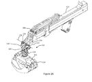
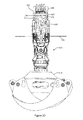
- Figures 2A , 2B , 2C , 2D , 2E , 2F, and 2G illustrate perspective, detailed, side, end, section (along section 2E-2E of Figure 2C ), top, and bottom views of a crane and a rotator link assembly, in accordance with an embodiment
- FIGS. 3A and 3B are perspective views of a rotator, in accordance with an embodiment.
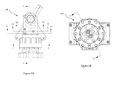
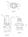
- Figures 4A, 4B , 4C, 4D, and 4E are front, bottom, top, side, and rear views, respectively, of the rotator of Figures 3A and 3B ;
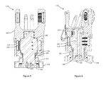
- Figure 5 is a section view of the rotator of Figures 3A and 3B along section 5-5 of Figure 4A ;
- Figure 6 is a section view of the rotator of Figures 3A and 3B along section 6-6 of Figure 4B ;
- Figure 7 is a section view of the rotator of Figures 3A and 3B along section 7-7 of Figure 4A ;
- Figure 8 is a section view of the rotator of Figures 3A and 3B along section 8-8 of Figure 4C ;
- Figure 9 is a section view of the rotator of Figures 3A and 3B along section 9-9 of Figure 4C ;
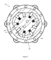
- Figure 10 is a section view of the rotator of Figures 3A and 3B along section 10-10 of Figure 4C ;
- Figure 11 is a section view of the rotator of Figures 3A and 3B along section 11-11 of Figure 4A ;
- Figure 12 is a section view of the rotator of Figures 3A and 3B along section 12-12 of Figure 4A ;
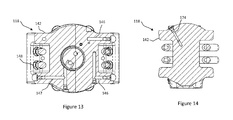
- Figure 13 is a section view of the rotator of Figures 3A and 3B along section 13-13 of Figure 4E ;
- Figure 14 is a section view of the rotator of Figures 3A and 3B along section 14-14 of Figure 4A ;
- Figure 15 is a schematic diagram of the connection axes of the rotator of Figures 3A and 3B ;
- Figure 16 is a schematic diagram of the crane connection axis of the crane of Figures 2A to 2G .
- the present disclosure provides a hydraulic assembly and, in particular a hydraulic assembly for a rotator link assembly for passing hydraulic fluid from a crane to a hydraulic drive.
- a hydraulic assembly for a rotator link assembly for passing hydraulic fluid from a crane to a hydraulic drive.
- the embodiments of the hydraulic assembly are described as an element of a rotator link assembly; however, one of skill in the art will understand that the hydraulic assembly may be applied in other hydraulic systems.
- FIG. 1 illustrates an example of logging equipment where a rotator link assembly 10 may be used.
- the logging equipment is a forwarder 12.
- An operator of the forwarder 12 maneuvers a crane 14 above objects (e.g. logs) 16 to be picked up and actuates a grapple implement 18 to close arms of the grapple implement 18 around the logs 16.
- the crane 14 may have a telescopic boom which extends telescopically along the length of the crane 14. Either before or after the arms of the grapple implement 18 are closed, the operator may use the rotator link assembly 10 to rotate the grapple implement 18 while also manipulating the crane 14.
- the operator can load the logs 16 into a trailer 20.
- the rotator link assembly 10 in Figure 1 is a conventional rotator link assembly but could be replaced by a rotator link assembly as described herein. It will further be understood that the rotator link assembly as described herein may be used in a variety of operations, not limited to the forwarder 12 or other logging applications.
- FIGS 2A to 2G illustrate various views of a crane 112 having a rotator link assembly 100, in accordance with an embodiment.
- the rotator link assembly 100 attaches on a distal end 113 of the crane 112.
- the other end of the rotator link assembly 100 connects to an implement 114.
- the implement 114 is a grappler.
- the implement 114 may be any type of implement 114 which operates using hydraulics, as is known in the art.
- the rotator link assembly 100 is particularly useful where rotation about at least one axis and actuation of an implement is desired.
- the rotator link assembly 100 includes a link 116 and a rotator 118.
- the link 116 connects to the rotator 118 by a first pivot connection 120 having a first axis 122.
- the first axis 122 may be horizontal in an at rest configuration.
- the link 116 also connects to the distal end 113 of the crane 112 by a second pivot connection 124 having a second axis 126.
- the second axis 126 may also be horizontal in an at rest configuration but is oriented perpendicular to the first pivot axis 122.
- the pivot connections 120, 124 thus allow the rotator 118 to rotate freely about the first and second axes 122, 126.
- the first pivot connection 120 includes a pair of laterally spaced pins 128, 130 and the second pivot connection 124 includes a pair of laterally spaced pins 132, 134.
- the pivot pins 128, 130, 132, 134 are spaced to allow hydraulic conduits 136, 137 to pass therebetween.
- the first pivot connection 120 may include a friction device 138 for dampening motion about the first axis 122 due to the movement of the rotator 118.
- Figures 3A and 3B illustrate the rotator 118, in accordance with an embodiment.
- Figures 4A, 4B , 4C, 4D, and 4E illustrate front, bottom, top, side, and rear views of the rotator 118.
- Figures 5-14 illustrate sectional views of the rotator 118.
- the rotator 118 rotates the implement 114 around a rotation axis 144.
- the rotation axis 144 is vertical in an at rest configuration and perpendicular to one or both of the first axis 122 and the second axis 126.
- the rotation axis 144 is perpendicular to the pins 128, 130 between the link 116 and rotator 118.
- the pins 128, 130 engage with bearings129a, 129b of the rotator 118.
- the rotator 118 includes a rotary manifold 142 housing a hydraulic motor 140 (rotational drive) and a rotate shaft 150.
- the hydraulic motor 140 is integral to the rotator 118 and powers rotation of the rotate shaft 150 about the rotation axis 144.
- the rotate shaft 150 is affixed to the implement 114 by a taper lock bushing 152, retaining bolts 154, and an implement attachment 156, such that the implement 114 will rotate with respect to the rotary manifold 142 about the rotation axis 144.
- hydraulic fluid is supplied from a hydraulic pump or controller (not shown) at the crane 112 to two hydraulic drives at the rotator 118 via hydraulic conduits 136, 137.
- the hydraulic drives include the hydraulic motor 140 and the implement 114 but there may be embodiments where there may be one hydraulic drive or a plurality of hydraulic drives.
- the hydraulic conduits 136, 137 are generally flexible hoses, as is known in the art.
- both the hydraulic pump/controller and the hydraulic drives will be referred to as hydraulic elements.
- the hydraulic controller includes a pump, valves, and user controls as is known in the art.
- a first pair of the hydraulic conduits 136 powers and controls the hydraulic motor 140.
- the hydraulic fluid supplied by the hydraulic conduits 136 passes into and out of passages 146 in the rotary manifold 142 and into pressure and return portions of the hydraulic motor 140.
- a check valve and check valve conduit 174 can be provided in the rotary manifold 142 to compensate for any hydraulic fluid leaks.
- the rotate shaft 150 includes vanes 158 which are driven by the hydraulic motor 140 to rotate the rotate shaft 150 about the rotation axis 144.
- a second pair of the hydraulic conduits 137 provides hydraulic fluid to actuate hydraulic cylinder 139 of the implement 114.
- the second set of hydraulic conduits 137 pass hydraulic fluid through passages 147 in the rotary manifold 142 to the rotate shaft 150.
- the hydraulic fluid then passes through passages 149 in the rotate shaft 150 to openings 162 on an external surface 164 at the opposite end of the rotate shaft 150.
- the hydraulic fluid then passes through to the hydraulic cylinder 139 of the implement 114.
- the hydraulic fluid in the passages 147 can be sealed with seals 160.
- the first pair of hydraulic conduits 136 includes a first motor conduit 136a for supplying hydraulic fluid to rotate the hydraulic motor 140 clockwise (as viewed from the top of the rotator 142, e.g. Figure 2F ).
- the first pair of hydraulic conduits 136 also includes a second motor conduit 136b for supplying hydraulic fluid to rotate the hydraulic motor 140 counter-clockwise (as viewed from the top of the rotator 142, e.g. Figure 2F ).
- the second pair of hydraulic conduits 137 includes a first grapple conduit 137a for supplying hydraulic fluid to close the implement 118.
- the second pair of hydraulic conduits 137 also includes a second grapple conduit 137b for supplying hydraulic fluid to open the implement 118.
- the rotate shaft 150 is supported by bearings 166 that transfer vertical loads from the implement 114 to the link 116 then to the crane 112 through the pins 128, 130, 132, 134. Horizontal loads are taken by contact between the rotate shaft 150 and the rotary manifold 142 at positions above and below the hydraulic motor 140.
- the rotator 118 includes connectors 148 for connecting the hydraulic conduits 136, 137 to the rotary manifold 142.
- Each of the connectors 148 has a connection axis 170 defined by the direction the hydraulic conduits 136, 137 connect to connectors 148.
- FIG 15 is a schematic drawing illustrating a hydraulic assembly 169, according to an embodiment herein.
- the hydraulic assembly 169 includes the first pivot connection 120 defining the first axis 122 and the connector 148 defining the connection axis 170 where the connectors 148 are configured such that the connection axis 170 approximately intersects the first axis 122.
- a generally similar hydraulic assembly 176 can be provided at the crane 112, where crane connectors 168 are provided to the crane 118 to connect the hydraulic conduits 136, 137 to the hydraulic controller (not shown).
- the placement of the crane connectors 168 defines a crane connection axis 171 which is directed to approximately intersect the second axis 126 of the second pivot connection 124 of the rotator link assembly 100.
- This configuration of the connectors 148, 168 on the rotator 118 and on the crane 112 such that the respective axes intersect related pivot axes is intended to reduce damage to the hydraulic conduits 136, 137 during operation. Further, the configuration is intended to permit the hydraulic conduits 136, 137 to flex naturally within hose design limits while minimizing the size of the rotator link assembly 100 with a compact design.
- approximately intersecting is intended to include a range of values based on various factors, for example, the diameter of the hydraulic conduit 136, 137, the allowable bend radius of the hydraulic conduit 136, 137, the distance between the connectors 148, 168 on either side of the first and second axes 122, 126, and the length of the hydraulic conduits 136, 137.
- “approximately intersecting” may include a situation where the connection axis 170, 171 is within a radius of the hydraulic conduit 136, 137 of intersecting the axis 122, 126.
- connectors 148 connected with hydraulic conduits 136, 137 having an outside diameter of 23.4 mm and the connection axis 170 passed within 18.5 mm of the first axis 122 (measured perpendicular to the first axis 122), the hydraulic conduits 136, 137 moved through a desired range of motion and appeared to function acceptably during testing.
- connection axes 170, 171 passes further away from the first and second pivot axis 122, 126, buckling of the hydraulic conduits 136, 137 may occur. Further, where the connection axes 170, 171 do not approximately intersect the first and second axes 122, 126, the hydraulic conduits 136, 137 may undesirably bend in the wrong direction during pivoting.
- the configuration of the embodiments herein is also beneficial because it allows for a compact design. For example, if the hydraulic conduits 136 or 137 are put into a linear position where the connectors 148 are rotated to face the connectors 168 and the respective connection axes pass through the first axis 122 and the second axis 126, this linear position determines the minimum length of the hydraulic conduit 136, 137. That is, to allow the connectors 148, 168 to be at the minimum distance possible for the most compact design, the connectors 148, 168 face directly at the first and second axes 122, 126. Although this configuration might provide the minimum distance, in practical applications, the hydraulic conduits 136, 137 may have some additional length, for example, at least one or two additional radius of length.
- the hydraulic conduits 136, 137 may buckle. If the connectors 148, 168 are farther from the first and second axes 122, 126, the hydraulic conduits 136, 137 may permissibly buckle within the bend radius of the hydraulic conduit 136, 137.
- a distance between the first axis 122 and the top of the rotator 118 may be reduced by also positioning the connectors 148 for the hydraulic conduits 136, 137 on the rotator 118 such that the connection axis 170 is not parallel with the rotation axis 144 of the hydraulic motor 140.
- the connection axis 170 may be at an angle 172 of 5 to 85 degrees with respect to the rotation axis 144. In other cases the angle may be between 20 and 70 degrees or between 30 and 60 degrees. In a particular case, the connection axis 170 may be at an angle 172 of approximately 30 degrees with respect to the rotation axis 144.
- the first axis 122 is positioned as close to the hydraulic connectors 148 as possible based on the flexibility and the design constraints of the hydraulic conduits 136, 137.
- the connectors 148, 168 are also positioned to generally route the hydraulic conduits 136, 137 between the pins 128, 130 of the first axis 122 and the pins 132, 134 of the second axis 126.
- hydraulic conduits typically run exposed outside of a link between the end of the crane and the implement.
- the hydraulic conduits 136, 137 pass through the pins 128, 130 of the first axis 122 and the pins 132, 134 of the second axis 126in a manner that reduces damage to the hydraulic conduits 136, 137 when the pivot pins 128, 130, 132, 134 articulate.
- the routing path of the hydraulic conduits 136, 137 between each pair of pins 128, 130 and 132, 134 at each axis 122, 126 is intended to protect the hydraulic conduits 136 from damage from external materials such as trees or the like to the rotator link assembly 100.
- the connectors 148 are not overly exposed, reducing the chance of accidental impact and damage and providing a compact design and access for repairs.
- the configuration of the connectors 148 to the rotator 118 may also reduce the need to provide a protective cover to the hydraulic conduits 136, 137.
- axes 122, 126, 144 are described as being, horizontal, horizontal, and vertical when at rest, it will be understood that these axes 122, 126, 144 need not be horizontal and vertical and the orientation may depend on the required orientation of the hydraulic assembly, and, in this embodiment, of the crane 112 and the rotator link assembly 100.
Landscapes
- Engineering & Computer Science (AREA)
- Mechanical Engineering (AREA)
- Life Sciences & Earth Sciences (AREA)
- Mining & Mineral Resources (AREA)
- Civil Engineering (AREA)
- General Engineering & Computer Science (AREA)
- Structural Engineering (AREA)
- Biodiversity & Conservation Biology (AREA)
- Ecology (AREA)
- Forests & Forestry (AREA)
- Environmental Sciences (AREA)
- Jib Cranes (AREA)
Abstract
Description
- The present disclosure relates generally to a hydraulic assembly. More particularly, the present disclosure relates to a hydraulic assembly for logging equipment and, even more particularly, to a hydraulic assembly for a rotator link assembly in logging equipment.
- Hydraulic assemblies, including hydraulic conduits, are used for the communication of pressurized fluid to drive hydraulic components. In some cases, the hydraulic components may be part of a mechanical system that includes pivot points for rotational movement of mechanical or hydraulic components.
- In a particular case, the hydraulic component may be for driving a rotator and an implement that are suspended at the end of a crane. In this case, hydraulic conduits run from a pressure medium source along a crane through a rotator link assembly and to the implement. The rotator link assembly includes a hydraulic component for driving rotation of the implement as well as a hydraulic component for operating the implement. The rotator link assembly also includes a pivot connection to the crane. In this situation, it may be difficult to provide durable hydraulic conduit connectors as the hydraulic conduits will be under stress as a result of the movement of the crane, pivot connection, rotator, and the implement.
- Further, when fed along a crane, via a rotator link assembly to an implement, the hydraulic conduits may be exposed to surrounding objects when the crane, pivot connection, or rotator moves and this may cause damage to the hydraulic conduits. Damage to the hydraulic conduits may lead to failure of the conduit and hydraulic fluid leakage. When damaged, the hydraulic conduits must be replaced causing reduced production and increased operational costs.
- Examples of conventional hydraulic conduit assemblies are described in United States Patent Application Publication No.
2013/0056588 to Harr et al. and United States Patent No.7,311,489 to Ekman . - It is, therefore, desirable to provide a hydraulic assembly configured to reduce hydraulic conduit failure.
- It is an object of the present disclosure to obviate or mitigate at least one disadvantage of previous hydraulic assemblies or systems.
- In an aspect, the present disclosure provides a hydraulic assembly including a pivot connection defining a pivot axis, a hydraulic element linked to the pivot connection, and a connector for connecting a hydraulic conduit to the hydraulic element. The connector defines a connection axis and the connector is configured such that the connection axis approximately intersects the pivot axis.
- In a particular case, the hydraulic element may include a hydraulic drive.
- In another particular case, the pivot connection may include a pair of pins attaching the hydraulic element to a link and the hydraulic conduit passes between the pair of pins.
- In the case of a hydraulic drive, the hydraulic drive defines a hydraulic drive axis and an angle between the connection axis and the hydraulic drive axis may be greater than approximately 5 degrees and less than approximately 85 degrees.
- In a further particular case, the angle may be approximately 30 degrees.
- In a further case, the hydraulic drive may include a rotational drive and the hydraulic drive axis is the axis of rotation of the rotational drive.
- In another aspect, the present disclosure provides equipment including a link, a rotator pivotally attached to the link at a first pivot connection defining a first pivot axis and a hydraulic assembly. The hydraulic assembly includes a hydraulic element provided to the rotator and a connector provided to the rotator for connecting a hydraulic conduit to the hydraulic element. The connector defines a connection axis and the connector is configured such that the connection axis approximately intersects the first pivot axis.
- In a particular case, the hydraulic element may be a rotational drive defining a rotation axis and an angle between the connection axis and the rotation axis may be greater than approximately 5 degrees and less than approximately 85 degrees. In a particular case, the angle may be approximately 30 degrees.
- In a particular case, the first pivot axis may be perpendicular to the rotation axis.
- In a further particular case, the first pivot connection may include a first pair of pins attaching the rotator to the link and the hydraulic conduit passes between the first pair of pins.
- In another particular case, the equipment further may include a crane and the link may be pivotally attached to the crane at a second pivot connection defining a second pivot axis.
- In a further particular case, the equipment may further include a crane connector provided to the crane for connecting the hydraulic conduit to the crane. The crane connector defines a crane connection axis and the crane connector is configured such that the crane connection axis approximately intersects the second pivot axis.
- In a further particular case, the second pivot axis may be perpendicular to the first pivot axis.
- In a further particular case, the second pivot connection may include a second pair of pins attaching the link to the crane and the hydraulic conduit passes between the second pair of pins.
- In a further case, the hydraulic element may be an implement provided to the rotator and the hydraulic conduit supplies hydraulic fluid to the implement.
- In still a further case, the implement may be a grappler.
- In yet a further case, the hydraulic element may include a plurality of hydraulic elements and the hydraulic conduit may include a plurality of hydraulic conduits supplying hydraulic fluid to the plurality of hydraulic elements.
- In this case, the plurality of hydraulic elements may include a rotational drive and a grappler.
- Other aspects and features of the present disclosure will become apparent to those ordinarily skilled in the art upon review of the following description of specific embodiments in conjunction with the accompanying figures.
- Embodiments of the present disclosure will now be described, by way of example only, with reference to the attached Figures.
-
Figure 1 is a photograph of logging equipment, and, in particular, a forwarder, having a rotator link assembly; -
Figures 2A ,2B ,2C ,2D ,2E ,2F, and 2G illustrate perspective, detailed, side, end, section (alongsection 2E-2E ofFigure 2C ), top, and bottom views of a crane and a rotator link assembly, in accordance with an embodiment; -
Figures 3A and 3B are perspective views of a rotator, in accordance with an embodiment. -
Figures 4A, 4B ,4C, 4D, and 4E are front, bottom, top, side, and rear views, respectively, of the rotator ofFigures 3A and 3B ; -
Figure 5 is a section view of the rotator ofFigures 3A and 3B along section 5-5 ofFigure 4A ; -
Figure 6 is a section view of the rotator ofFigures 3A and 3B along section 6-6 ofFigure 4B ; -
Figure 7 is a section view of the rotator ofFigures 3A and 3B along section 7-7 ofFigure 4A ; -
Figure 8 is a section view of the rotator ofFigures 3A and 3B along section 8-8 ofFigure 4C ; -
Figure 9 is a section view of the rotator ofFigures 3A and 3B along section 9-9 ofFigure 4C ; -
Figure 10 is a section view of the rotator ofFigures 3A and 3B along section 10-10 ofFigure 4C ; -
Figure 11 is a section view of the rotator ofFigures 3A and 3B along section 11-11 ofFigure 4A ; -
Figure 12 is a section view of the rotator ofFigures 3A and 3B along section 12-12 ofFigure 4A ; -
Figure 13 is a section view of the rotator ofFigures 3A and 3B along section 13-13 ofFigure 4E ; -
Figure 14 is a section view of the rotator ofFigures 3A and 3B along section 14-14 ofFigure 4A ; -
Figure 15 is a schematic diagram of the connection axes of the rotator ofFigures 3A and 3B ; and -
Figure 16 is a schematic diagram of the crane connection axis of the crane ofFigures 2A to 2G . - Generally, the present disclosure provides a hydraulic assembly and, in particular a hydraulic assembly for a rotator link assembly for passing hydraulic fluid from a crane to a hydraulic drive. In this disclosure, the embodiments of the hydraulic assembly are described as an element of a rotator link assembly; however, one of skill in the art will understand that the hydraulic assembly may be applied in other hydraulic systems.
-
Figure 1 illustrates an example of logging equipment where arotator link assembly 10 may be used. In this case, the logging equipment is aforwarder 12. An operator of the forwarder 12 maneuvers acrane 14 above objects (e.g. logs) 16 to be picked up and actuates a grapple implement 18 to close arms of the grapple implement 18 around thelogs 16. Thecrane 14 may have a telescopic boom which extends telescopically along the length of thecrane 14. Either before or after the arms of the grapple implement 18 are closed, the operator may use therotator link assembly 10 to rotate the grapple implement 18 while also manipulating thecrane 14. By appropriately operating therotator link assembly 10 and grapple implement 18, the operator can load thelogs 16 into atrailer 20. Therotator link assembly 10 inFigure 1 is a conventional rotator link assembly but could be replaced by a rotator link assembly as described herein. It will further be understood that the rotator link assembly as described herein may be used in a variety of operations, not limited to the forwarder 12 or other logging applications. -
Figures 2A to 2G illustrate various views of acrane 112 having arotator link assembly 100, in accordance with an embodiment. Therotator link assembly 100 attaches on adistal end 113 of thecrane 112. The other end of therotator link assembly 100 connects to an implement 114. In the embodiment shown, the implement 114 is a grappler. The implement 114 may be any type of implement 114 which operates using hydraulics, as is known in the art. Therotator link assembly 100 is particularly useful where rotation about at least one axis and actuation of an implement is desired. - As shown in more detail in
Figure 2B , therotator link assembly 100 includes alink 116 and arotator 118. Thelink 116 connects to therotator 118 by afirst pivot connection 120 having afirst axis 122. Thefirst axis 122 may be horizontal in an at rest configuration. Thelink 116 also connects to thedistal end 113 of thecrane 112 by asecond pivot connection 124 having asecond axis 126. Thesecond axis 126 may also be horizontal in an at rest configuration but is oriented perpendicular to thefirst pivot axis 122. Thepivot connections rotator 118 to rotate freely about the first andsecond axes first pivot connection 120 includes a pair of laterally spacedpins second pivot connection 124 includes a pair of laterally spacedpins hydraulic conduits first pivot connection 120 may include afriction device 138 for dampening motion about thefirst axis 122 due to the movement of therotator 118. -
Figures 3A and 3B illustrate therotator 118, in accordance with an embodiment.Figures 4A, 4B ,4C, 4D, and 4E illustrate front, bottom, top, side, and rear views of therotator 118.Figures 5-14 illustrate sectional views of therotator 118. - The
rotator 118 rotates the implement 114 around arotation axis 144. Therotation axis 144 is vertical in an at rest configuration and perpendicular to one or both of thefirst axis 122 and thesecond axis 126. Therotation axis 144 is perpendicular to thepins link 116 androtator 118. Thepins rotator 118. - The
rotator 118 includes arotary manifold 142 housing a hydraulic motor 140 (rotational drive) and a rotateshaft 150. Thehydraulic motor 140 is integral to therotator 118 and powers rotation of the rotateshaft 150 about therotation axis 144. The rotateshaft 150 is affixed to the implement 114 by ataper lock bushing 152, retainingbolts 154, and an implementattachment 156, such that the implement 114 will rotate with respect to therotary manifold 142 about therotation axis 144. - As shown in
Figures 2A-2G , hydraulic fluid is supplied from a hydraulic pump or controller (not shown) at thecrane 112 to two hydraulic drives at therotator 118 viahydraulic conduits hydraulic motor 140 and the implement 114 but there may be embodiments where there may be one hydraulic drive or a plurality of hydraulic drives. Thehydraulic conduits - A first pair of the
hydraulic conduits 136 powers and controls thehydraulic motor 140. The hydraulic fluid supplied by thehydraulic conduits 136 passes into and out ofpassages 146 in therotary manifold 142 and into pressure and return portions of thehydraulic motor 140. A check valve andcheck valve conduit 174 can be provided in therotary manifold 142 to compensate for any hydraulic fluid leaks. The rotateshaft 150 includesvanes 158 which are driven by thehydraulic motor 140 to rotate the rotateshaft 150 about therotation axis 144. - A second pair of the
hydraulic conduits 137 provides hydraulic fluid to actuatehydraulic cylinder 139 of the implement 114. The second set ofhydraulic conduits 137 pass hydraulic fluid throughpassages 147 in therotary manifold 142 to the rotateshaft 150. The hydraulic fluid then passes throughpassages 149 in the rotateshaft 150 toopenings 162 on anexternal surface 164 at the opposite end of the rotateshaft 150. The hydraulic fluid then passes through to thehydraulic cylinder 139 of the implement 114. The hydraulic fluid in thepassages 147 can be sealed withseals 160. - As shown in
Figures 3A and 3B , the first pair ofhydraulic conduits 136 includes afirst motor conduit 136a for supplying hydraulic fluid to rotate thehydraulic motor 140 clockwise (as viewed from the top of therotator 142, e.g.Figure 2F ). The first pair ofhydraulic conduits 136 also includes asecond motor conduit 136b for supplying hydraulic fluid to rotate thehydraulic motor 140 counter-clockwise (as viewed from the top of therotator 142, e.g.Figure 2F ). The second pair ofhydraulic conduits 137 includes a first grappleconduit 137a for supplying hydraulic fluid to close the implement 118. The second pair ofhydraulic conduits 137 also includes a second grappleconduit 137b for supplying hydraulic fluid to open the implement 118. - The rotate
shaft 150 is supported bybearings 166 that transfer vertical loads from the implement 114 to thelink 116 then to thecrane 112 through thepins shaft 150 and therotary manifold 142 at positions above and below thehydraulic motor 140. - The
rotator 118 includesconnectors 148 for connecting thehydraulic conduits rotary manifold 142. Each of theconnectors 148 has aconnection axis 170 defined by the direction thehydraulic conduits connectors 148. -
Figure 15 is a schematic drawing illustrating ahydraulic assembly 169, according to an embodiment herein. In particular, thehydraulic assembly 169 includes thefirst pivot connection 120 defining thefirst axis 122 and theconnector 148 defining theconnection axis 170 where theconnectors 148 are configured such that theconnection axis 170 approximately intersects thefirst axis 122. As shown infigure 16 with reference tofigures 2A to 2G , a generally similarhydraulic assembly 176 can be provided at thecrane 112, wherecrane connectors 168 are provided to thecrane 118 to connect thehydraulic conduits crane connectors 168 defines acrane connection axis 171 which is directed to approximately intersect thesecond axis 126 of thesecond pivot connection 124 of therotator link assembly 100. - This configuration of the
connectors rotator 118 and on thecrane 112 such that the respective axes intersect related pivot axes is intended to reduce damage to thehydraulic conduits hydraulic conduits rotator link assembly 100 with a compact design. - In embodiments herein, "approximately intersecting" is intended to include a range of values based on various factors, for example, the diameter of the
hydraulic conduit hydraulic conduit connectors second axes hydraulic conduits connection axis hydraulic conduit axis connectors 148 connected withhydraulic conduits connection axis 170 passed within 18.5 mm of the first axis 122 (measured perpendicular to the first axis 122), thehydraulic conduits - The configuration of the embodiments herein is beneficial because, when the connection axes 170, 171 passes further away from the first and
second pivot axis hydraulic conduits second axes hydraulic conduits - The configuration of the embodiments herein is also beneficial because it allows for a compact design. For example, if the
hydraulic conduits connectors 148 are rotated to face theconnectors 168 and the respective connection axes pass through thefirst axis 122 and thesecond axis 126, this linear position determines the minimum length of thehydraulic conduit connectors connectors second axes hydraulic conduits - When the
connectors second axes hydraulic conduits second axes hydraulic conduits connectors second axes hydraulic conduits hydraulic conduit - In the embodiment of the
rotator link assembly 100, a distance between thefirst axis 122 and the top of therotator 118 may be reduced by also positioning theconnectors 148 for thehydraulic conduits rotator 118 such that theconnection axis 170 is not parallel with therotation axis 144 of thehydraulic motor 140. For example, theconnection axis 170 may be at anangle 172 of 5 to 85 degrees with respect to therotation axis 144. In other cases the angle may be between 20 and 70 degrees or between 30 and 60 degrees. In a particular case, theconnection axis 170 may be at anangle 172 of approximately 30 degrees with respect to therotation axis 144. Generally speaking, thefirst axis 122 is positioned as close to thehydraulic connectors 148 as possible based on the flexibility and the design constraints of thehydraulic conduits - As shown in, for example,
figure 2B , theconnectors hydraulic conduits pins first axis 122 and thepins second axis 126. - In conventional systems, hydraulic conduits typically run exposed outside of a link between the end of the crane and the implement. In contrast, the
hydraulic conduits pins first axis 122 and thepins hydraulic conduits hydraulic conduits pins axis hydraulic conduits 136 from damage from external materials such as trees or the like to therotator link assembly 100. - The
connectors 148 are not overly exposed, reducing the chance of accidental impact and damage and providing a compact design and access for repairs. The configuration of theconnectors 148 to therotator 118 may also reduce the need to provide a protective cover to thehydraulic conduits - While the
axes axes crane 112 and therotator link assembly 100. - In the preceding description, for purposes of explanation, numerous details are set forth in order to provide a thorough understanding of the embodiments. However, it will be apparent to one skilled in the art that these specific details may not be required. In other instances, well-known structures may be shown in block diagram form in order not to obscure the understanding. The above-described embodiments are intended to be examples only. Alterations, modifications and variations can be effected to the particular embodiments by those of skill in the art without departing from the scope, which is defined solely by the claims appended hereto.
Claims (15)
- Equipment comprising:a link (116);a rotator (118) pivotally attached to the link (116) at a first pivot connection (120) defining a first pivot axis (122); anda hydraulic assembly, the hydraulic assembly comprising:a hydraulic element provided to the rotator (118); anda connector (148) provided to the rotator for connecting a hydraulic conduit (136, 137) to the hydraulic element, wherein the connector (148) defines a connection axis (170);wherein the connector (148) is configured such that the connection axis (170) approximately intersects the first pivot axis (122).
- The equipment of claim 1, wherein the hydraulic element is a rotational drive defining a rotation axis (144) and an angle (172) between the connection axis (170) and the rotation axis (144) is greater than approximately 5 degrees and less than approximately 85 degrees.
- The equipment of claim 2, wherein the angle (172) is approximately 30 degrees.
- The equipment of claim 2, wherein the first pivot axis (122) is perpendicular to the rotation axis (144).
- The equipment of claim 1 wherein the first pivot connection (170) comprises a first pair of pins (128, 130) attaching the rotator (118) to the link (116) and the hydraulic conduit (136, 137) passes between the first pair of pins (128, 130).
- The equipment of claim 1, further comprising a crane (112) and the link (116) is pivotally attached to the crane (112) at a second pivot connection (124) defining a second pivot axis (126).
- The equipment of claim 6 further comprising:a crane connector (168) provided to the crane (112) for connecting the hydraulic conduit (136, 137) to the crane (112), wherein the crane connector (168) defines a crane connection axis (171), and wherein the crane connector (168) is configured such that the crane connection axis (171) approximately intersects the second pivot axis (126).
- The equipment of claim 7, wherein the second pivot axis (126) is perpendicular to the first pivot axis (122).
- The equipment of claim 6, wherein the second pivot connection (124) comprises a second pair of pins (132, 134) attaching the link (116) to the crane (112) and the hydraulic conduit (136, 137) passes between the second pair of pins (132, 134).
- The equipment of claim 1, wherein the hydraulic element is an implement (114) provided to the rotator (118) and the hydraulic conduit (137) supplies hydraulic fluid to the implement (114).
- The equipment of claim 10, wherein the implement (114) is a grappler.
- The equipment of claim 1, wherein the hydraulic element comprises a plurality of hydraulic elements and the hydraulic conduit (136, 137) comprises a plurality of hydraulic conduits (136, 137) supplying hydraulic fluid to the plurality of hydraulic elements.
- The equipment of claim 12, wherein the plurality of hydraulic elements comprises a rotational drive and a grappler (114).
- A hydraulic assembly comprising:a pivot connection (120, 124) defining a pivot axis (122, 126);a hydraulic element linked to the pivot connection (120, 124); anda connector (148, 168) for connecting a hydraulic conduit (136, 137) to the hydraulic element, wherein the connector (148, 168) defines a connection axis (170, 171); andwherein the connector (148, 168) is configured such that the connection axis (170, 171) approximately intersects the pivot axis (122, 126).
- The hydraulic assembly of claim 14, wherein the pivot connection (120, 124) comprises:a pair of pins (128, 130, 132, 134) attaching the hydraulic elements to a link (116); andwherein the hydraulic conduit (136, 137) passes between the pair of pins (128, 130, 132, 134).
Applications Claiming Priority (2)
| Application Number | Priority Date | Filing Date | Title |
|---|---|---|---|
| CA2820565A CA2820565C (en) | 2013-07-10 | 2013-07-10 | Hydraulic assembly and logging equipment using same |
| US13/938,728 US10100487B2 (en) | 2013-07-10 | 2013-07-10 | Hydraulic assembly and logging equipment using same |
Publications (2)
| Publication Number | Publication Date |
|---|---|
| EP2824059A1 true EP2824059A1 (en) | 2015-01-14 |
| EP2824059B1 EP2824059B1 (en) | 2021-03-03 |
Family
ID=49033851
Family Applications (1)
| Application Number | Title | Priority Date | Filing Date |
|---|---|---|---|
| EP13181144.0A Active EP2824059B1 (en) | 2013-07-10 | 2013-08-21 | Hydraulic assembly and logging equipment using same |
Country Status (1)
| Country | Link |
|---|---|
| EP (1) | EP2824059B1 (en) |
Cited By (4)
| Publication number | Priority date | Publication date | Assignee | Title |
|---|---|---|---|---|
| WO2017191357A1 (en) * | 2016-05-03 | 2017-11-09 | Ponsse Oyj | Arrangement in the hoisting apparatus of a work machine, hoisting apparatus of a work machine, and work machine |
| WO2020099722A1 (en) * | 2018-11-15 | 2020-05-22 | Ponsse Oyj | Joint element provided with swing dampener brake, joint assembly comprising the joint element, and machine comprising the joint assembly |
| RU2781861C1 (en) * | 2018-11-15 | 2022-10-19 | Понссе Ойй | Connecting element supplied with swing damper brake, connecting assembly containing connecting element and machine containing connecting assembly |
| CN115289087A (en) * | 2022-09-28 | 2022-11-04 | 宁波中意液压马达有限公司 | Rotating motor for engineering vehicle gripping apparatus |
Citations (4)
| Publication number | Priority date | Publication date | Assignee | Title |
|---|---|---|---|---|
| US4211252A (en) * | 1978-02-01 | 1980-07-08 | The Yaun-Williams Bucket Co. | Hydraulic coupler |
| WO2003057615A1 (en) * | 2001-11-26 | 2003-07-17 | Cranab Ab | Device for mounting of a turnable implement |
| JP2009274806A (en) * | 2008-05-14 | 2009-11-26 | Hitachi Constr Mach Co Ltd | Handling device for hydraulic hose of suspended grapple |
| WO2011142704A1 (en) * | 2010-04-13 | 2011-11-17 | Indexator Ab | Arrangement related to guiding of hoses and/or cables |
Family Cites Families (4)
| Publication number | Priority date | Publication date | Assignee | Title |
|---|---|---|---|---|
| CA2353239A1 (en) * | 2001-07-18 | 2003-01-18 | Rotobec Inc. | Motor-driven, boom-mounted rotor assembly |
| DE10361583A1 (en) * | 2003-12-23 | 2005-07-21 | Holp Gmbh | Quick change system for the optional connection of various tools with a crane handle |
| JP4650571B2 (en) * | 2009-01-05 | 2011-03-16 | コベルコ建機株式会社 | Hydraulic crusher |
| EP2789565B1 (en) * | 2013-04-08 | 2015-09-09 | Penz crane GmbH | Fastening device for a rotatable tool attached to a crane |
-
2013
- 2013-08-21 EP EP13181144.0A patent/EP2824059B1/en active Active
Patent Citations (6)
| Publication number | Priority date | Publication date | Assignee | Title |
|---|---|---|---|---|
| US4211252A (en) * | 1978-02-01 | 1980-07-08 | The Yaun-Williams Bucket Co. | Hydraulic coupler |
| WO2003057615A1 (en) * | 2001-11-26 | 2003-07-17 | Cranab Ab | Device for mounting of a turnable implement |
| US7311489B2 (en) | 2001-11-26 | 2007-12-25 | Komatsu Forest Ab | Device for mounting of a turnable implement |
| JP2009274806A (en) * | 2008-05-14 | 2009-11-26 | Hitachi Constr Mach Co Ltd | Handling device for hydraulic hose of suspended grapple |
| WO2011142704A1 (en) * | 2010-04-13 | 2011-11-17 | Indexator Ab | Arrangement related to guiding of hoses and/or cables |
| US20130056588A1 (en) | 2010-04-13 | 2013-03-07 | Joakim Harr | Arrangement related to guiding of hoses and/or cables |
Cited By (8)
| Publication number | Priority date | Publication date | Assignee | Title |
|---|---|---|---|---|
| WO2017191357A1 (en) * | 2016-05-03 | 2017-11-09 | Ponsse Oyj | Arrangement in the hoisting apparatus of a work machine, hoisting apparatus of a work machine, and work machine |
| EP3452401A4 (en) * | 2016-05-03 | 2020-01-15 | Ponsse OYJ | ARRANGEMENT IN THE LIFTING APPARATUS OF A CONSTRUCTION MACHINE, APPARATUS FOR LIFTING A CONSTRUCTION MACHINE, AND CONSTRUCTION MACHINE |
| RU2735563C2 (en) * | 2016-05-03 | 2020-11-03 | Понссе Ойй | System in lifting mechanism of working machine, lifting mechanism of working machine and working machine |
| US11028552B2 (en) | 2016-05-03 | 2021-06-08 | Ponsse Oyj | Arrangement in the hoisting apparatus of a work machine, hoisting apparatus of a work machine, and work machine |
| WO2020099722A1 (en) * | 2018-11-15 | 2020-05-22 | Ponsse Oyj | Joint element provided with swing dampener brake, joint assembly comprising the joint element, and machine comprising the joint assembly |
| RU2781861C1 (en) * | 2018-11-15 | 2022-10-19 | Понссе Ойй | Connecting element supplied with swing damper brake, connecting assembly containing connecting element and machine containing connecting assembly |
| US12000430B2 (en) | 2018-11-15 | 2024-06-04 | Ponsse Oyj | Joint element provided with swing dampener brake, joint assembly comprising the joint element, and machine comprising the joint assembly |
| CN115289087A (en) * | 2022-09-28 | 2022-11-04 | 宁波中意液压马达有限公司 | Rotating motor for engineering vehicle gripping apparatus |
Also Published As
| Publication number | Publication date |
|---|---|
| EP2824059B1 (en) | 2021-03-03 |
Similar Documents
| Publication | Publication Date | Title |
|---|---|---|
| US10100487B2 (en) | Hydraulic assembly and logging equipment using same | |
| US11167958B2 (en) | Hose guiding device for a crane tool | |
| US5806313A (en) | Conduit arrangement for a construction machine | |
| RU2362725C2 (en) | Crane arm with fastening device for labour body | |
| US20070130935A1 (en) | Integrated valve assembly and computer controller for a distributed hydraulic control system | |
| US5049027A (en) | Hydro-electric tool lock | |
| EP2824059B1 (en) | Hydraulic assembly and logging equipment using same | |
| CA2820565C (en) | Hydraulic assembly and logging equipment using same | |
| EP3020874A1 (en) | A hydraulic control system for controlling a moveable device | |
| EP0719948A2 (en) | Straight travelling apparatus for heavy construction equipment | |
| EP2368065B1 (en) | Extendable pressurized fluid coupler | |
| US4382624A (en) | Grapple pivot snubber | |
| BRPI0823054B1 (en) | VARIABLE BITOLA SUBCHASSI FOR A VEHICLE AND METHOD FOR CONNECTING CABLES TO A SUBCHASSI | |
| US11028552B2 (en) | Arrangement in the hoisting apparatus of a work machine, hoisting apparatus of a work machine, and work machine | |
| GB2273282A (en) | Manipulator assembly | |
| EP3184699A1 (en) | A coupling apparatus | |
| US8905077B2 (en) | Hydraulic main valve and auxiliary valve | |
| FI111938B (en) | Control system for a boom set on a terrain moving machine | |
| US20050254933A1 (en) | Apparatus driven by a pressurized medium | |
| US20120160328A1 (en) | Hydraulic swivel | |
| EP3640514A1 (en) | Hydraulic joint and hydraulic boom crane assembly with a hydraulic joint | |
| US12331857B2 (en) | Apparatus with interlocking surfaces to secure angle of hydraulic coupling connections | |
| JP2556838Y2 (en) | Hydraulic circuit of cargo handling vehicle | |
| US12553215B2 (en) | Free rotating hydraulic joint for a vehicle attachment | |
| CZ17293U1 (en) | Crane boom |
Legal Events
| Date | Code | Title | Description |
|---|---|---|---|
| 17P | Request for examination filed |
Effective date: 20130821 |
|
| AK | Designated contracting states |
Kind code of ref document: A1 Designated state(s): AL AT BE BG CH CY CZ DE DK EE ES FI FR GB GR HR HU IE IS IT LI LT LU LV MC MK MT NL NO PL PT RO RS SE SI SK SM TR |
|
| AX | Request for extension of the european patent |
Extension state: BA ME |
|
| PUAI | Public reference made under article 153(3) epc to a published international application that has entered the european phase |
Free format text: ORIGINAL CODE: 0009012 |
|
| STAA | Information on the status of an ep patent application or granted ep patent |
Free format text: STATUS: EXAMINATION IS IN PROGRESS |
|
| 17Q | First examination report despatched |
Effective date: 20180327 |
|
| REG | Reference to a national code |
Ref country code: DE Ref legal event code: R079 Ref document number: 602013075986 Country of ref document: DE Free format text: PREVIOUS MAIN CLASS: B66C0013140000 Ipc: A01G0023000000 |
|
| GRAP | Despatch of communication of intention to grant a patent |
Free format text: ORIGINAL CODE: EPIDOSNIGR1 |
|
| STAA | Information on the status of an ep patent application or granted ep patent |
Free format text: STATUS: GRANT OF PATENT IS INTENDED |
|
| RIC1 | Information provided on ipc code assigned before grant |
Ipc: E02F 3/36 20060101ALI20200930BHEP Ipc: A01G 23/08 20060101ALI20200930BHEP Ipc: B66C 13/14 20060101ALI20200930BHEP Ipc: B66C 3/00 20060101ALI20200930BHEP Ipc: A01G 23/00 20060101AFI20200930BHEP Ipc: E02F 9/22 20060101ALI20200930BHEP |
|
| INTG | Intention to grant announced |
Effective date: 20201019 |
|
| GRAS | Grant fee paid |
Free format text: ORIGINAL CODE: EPIDOSNIGR3 |
|
| GRAA | (expected) grant |
Free format text: ORIGINAL CODE: 0009210 |
|
| STAA | Information on the status of an ep patent application or granted ep patent |
Free format text: STATUS: THE PATENT HAS BEEN GRANTED |
|
| AK | Designated contracting states |
Kind code of ref document: B1 Designated state(s): AL AT BE BG CH CY CZ DE DK EE ES FI FR GB GR HR HU IE IS IT LI LT LU LV MC MK MT NL NO PL PT RO RS SE SI SK SM TR |
|
| REG | Reference to a national code |
Ref country code: GB Ref legal event code: FG4D |
|
| REG | Reference to a national code |
Ref country code: AT Ref legal event code: REF Ref document number: 1366171 Country of ref document: AT Kind code of ref document: T Effective date: 20210315 Ref country code: CH Ref legal event code: EP |
|
| REG | Reference to a national code |
Ref country code: DE Ref legal event code: R096 Ref document number: 602013075986 Country of ref document: DE |
|
| REG | Reference to a national code |
Ref country code: IE Ref legal event code: FG4D |
|
| REG | Reference to a national code |
Ref country code: LT Ref legal event code: MG9D |
|
| PG25 | Lapsed in a contracting state [announced via postgrant information from national office to epo] |
Ref country code: NO Free format text: LAPSE BECAUSE OF FAILURE TO SUBMIT A TRANSLATION OF THE DESCRIPTION OR TO PAY THE FEE WITHIN THE PRESCRIBED TIME-LIMIT Effective date: 20210603 Ref country code: BG Free format text: LAPSE BECAUSE OF FAILURE TO SUBMIT A TRANSLATION OF THE DESCRIPTION OR TO PAY THE FEE WITHIN THE PRESCRIBED TIME-LIMIT Effective date: 20210603 Ref country code: HR Free format text: LAPSE BECAUSE OF FAILURE TO SUBMIT A TRANSLATION OF THE DESCRIPTION OR TO PAY THE FEE WITHIN THE PRESCRIBED TIME-LIMIT Effective date: 20210303 Ref country code: GR Free format text: LAPSE BECAUSE OF FAILURE TO SUBMIT A TRANSLATION OF THE DESCRIPTION OR TO PAY THE FEE WITHIN THE PRESCRIBED TIME-LIMIT Effective date: 20210604 Ref country code: FI Free format text: LAPSE BECAUSE OF FAILURE TO SUBMIT A TRANSLATION OF THE DESCRIPTION OR TO PAY THE FEE WITHIN THE PRESCRIBED TIME-LIMIT Effective date: 20210303 Ref country code: LT Free format text: LAPSE BECAUSE OF FAILURE TO SUBMIT A TRANSLATION OF THE DESCRIPTION OR TO PAY THE FEE WITHIN THE PRESCRIBED TIME-LIMIT Effective date: 20210303 |
|
| REG | Reference to a national code |
Ref country code: NL Ref legal event code: MP Effective date: 20210303 |
|
| REG | Reference to a national code |
Ref country code: AT Ref legal event code: MK05 Ref document number: 1366171 Country of ref document: AT Kind code of ref document: T Effective date: 20210303 |
|
| PG25 | Lapsed in a contracting state [announced via postgrant information from national office to epo] |
Ref country code: SE Free format text: LAPSE BECAUSE OF FAILURE TO SUBMIT A TRANSLATION OF THE DESCRIPTION OR TO PAY THE FEE WITHIN THE PRESCRIBED TIME-LIMIT Effective date: 20210303 Ref country code: LV Free format text: LAPSE BECAUSE OF FAILURE TO SUBMIT A TRANSLATION OF THE DESCRIPTION OR TO PAY THE FEE WITHIN THE PRESCRIBED TIME-LIMIT Effective date: 20210303 Ref country code: RS Free format text: LAPSE BECAUSE OF FAILURE TO SUBMIT A TRANSLATION OF THE DESCRIPTION OR TO PAY THE FEE WITHIN THE PRESCRIBED TIME-LIMIT Effective date: 20210303 Ref country code: PL Free format text: LAPSE BECAUSE OF FAILURE TO SUBMIT A TRANSLATION OF THE DESCRIPTION OR TO PAY THE FEE WITHIN THE PRESCRIBED TIME-LIMIT Effective date: 20210303 |
|
| PG25 | Lapsed in a contracting state [announced via postgrant information from national office to epo] |
Ref country code: NL Free format text: LAPSE BECAUSE OF FAILURE TO SUBMIT A TRANSLATION OF THE DESCRIPTION OR TO PAY THE FEE WITHIN THE PRESCRIBED TIME-LIMIT Effective date: 20210303 |
|
| PG25 | Lapsed in a contracting state [announced via postgrant information from national office to epo] |
Ref country code: SM Free format text: LAPSE BECAUSE OF FAILURE TO SUBMIT A TRANSLATION OF THE DESCRIPTION OR TO PAY THE FEE WITHIN THE PRESCRIBED TIME-LIMIT Effective date: 20210303 Ref country code: AT Free format text: LAPSE BECAUSE OF FAILURE TO SUBMIT A TRANSLATION OF THE DESCRIPTION OR TO PAY THE FEE WITHIN THE PRESCRIBED TIME-LIMIT Effective date: 20210303 Ref country code: CZ Free format text: LAPSE BECAUSE OF FAILURE TO SUBMIT A TRANSLATION OF THE DESCRIPTION OR TO PAY THE FEE WITHIN THE PRESCRIBED TIME-LIMIT Effective date: 20210303 Ref country code: EE Free format text: LAPSE BECAUSE OF FAILURE TO SUBMIT A TRANSLATION OF THE DESCRIPTION OR TO PAY THE FEE WITHIN THE PRESCRIBED TIME-LIMIT Effective date: 20210303 |
|
| PG25 | Lapsed in a contracting state [announced via postgrant information from national office to epo] |
Ref country code: IS Free format text: LAPSE BECAUSE OF FAILURE TO SUBMIT A TRANSLATION OF THE DESCRIPTION OR TO PAY THE FEE WITHIN THE PRESCRIBED TIME-LIMIT Effective date: 20210703 Ref country code: RO Free format text: LAPSE BECAUSE OF FAILURE TO SUBMIT A TRANSLATION OF THE DESCRIPTION OR TO PAY THE FEE WITHIN THE PRESCRIBED TIME-LIMIT Effective date: 20210303 Ref country code: ES Free format text: LAPSE BECAUSE OF FAILURE TO SUBMIT A TRANSLATION OF THE DESCRIPTION OR TO PAY THE FEE WITHIN THE PRESCRIBED TIME-LIMIT Effective date: 20210303 Ref country code: PT Free format text: LAPSE BECAUSE OF FAILURE TO SUBMIT A TRANSLATION OF THE DESCRIPTION OR TO PAY THE FEE WITHIN THE PRESCRIBED TIME-LIMIT Effective date: 20210705 Ref country code: SK Free format text: LAPSE BECAUSE OF FAILURE TO SUBMIT A TRANSLATION OF THE DESCRIPTION OR TO PAY THE FEE WITHIN THE PRESCRIBED TIME-LIMIT Effective date: 20210303 |
|
| REG | Reference to a national code |
Ref country code: DE Ref legal event code: R097 Ref document number: 602013075986 Country of ref document: DE |
|
| PLBE | No opposition filed within time limit |
Free format text: ORIGINAL CODE: 0009261 |
|
| STAA | Information on the status of an ep patent application or granted ep patent |
Free format text: STATUS: NO OPPOSITION FILED WITHIN TIME LIMIT |
|
| PG25 | Lapsed in a contracting state [announced via postgrant information from national office to epo] |
Ref country code: DK Free format text: LAPSE BECAUSE OF FAILURE TO SUBMIT A TRANSLATION OF THE DESCRIPTION OR TO PAY THE FEE WITHIN THE PRESCRIBED TIME-LIMIT Effective date: 20210303 Ref country code: AL Free format text: LAPSE BECAUSE OF FAILURE TO SUBMIT A TRANSLATION OF THE DESCRIPTION OR TO PAY THE FEE WITHIN THE PRESCRIBED TIME-LIMIT Effective date: 20210303 |
|
| 26N | No opposition filed |
Effective date: 20211206 |
|
| PG25 | Lapsed in a contracting state [announced via postgrant information from national office to epo] |
Ref country code: SI Free format text: LAPSE BECAUSE OF FAILURE TO SUBMIT A TRANSLATION OF THE DESCRIPTION OR TO PAY THE FEE WITHIN THE PRESCRIBED TIME-LIMIT Effective date: 20210303 |
|
| REG | Reference to a national code |
Ref country code: CH Ref legal event code: PL |
|
| PG25 | Lapsed in a contracting state [announced via postgrant information from national office to epo] |
Ref country code: MC Free format text: LAPSE BECAUSE OF FAILURE TO SUBMIT A TRANSLATION OF THE DESCRIPTION OR TO PAY THE FEE WITHIN THE PRESCRIBED TIME-LIMIT Effective date: 20210303 |
|
| REG | Reference to a national code |
Ref country code: BE Ref legal event code: MM Effective date: 20210831 |
|
| PG25 | Lapsed in a contracting state [announced via postgrant information from national office to epo] |
Ref country code: LI Free format text: LAPSE BECAUSE OF NON-PAYMENT OF DUE FEES Effective date: 20210831 Ref country code: IT Free format text: LAPSE BECAUSE OF FAILURE TO SUBMIT A TRANSLATION OF THE DESCRIPTION OR TO PAY THE FEE WITHIN THE PRESCRIBED TIME-LIMIT Effective date: 20210303 Ref country code: CH Free format text: LAPSE BECAUSE OF NON-PAYMENT OF DUE FEES Effective date: 20210831 |
|
| PG25 | Lapsed in a contracting state [announced via postgrant information from national office to epo] |
Ref country code: IS Free format text: LAPSE BECAUSE OF FAILURE TO SUBMIT A TRANSLATION OF THE DESCRIPTION OR TO PAY THE FEE WITHIN THE PRESCRIBED TIME-LIMIT Effective date: 20210703 Ref country code: LU Free format text: LAPSE BECAUSE OF NON-PAYMENT OF DUE FEES Effective date: 20210821 |
|
| PG25 | Lapsed in a contracting state [announced via postgrant information from national office to epo] |
Ref country code: IE Free format text: LAPSE BECAUSE OF NON-PAYMENT OF DUE FEES Effective date: 20210821 Ref country code: BE Free format text: LAPSE BECAUSE OF NON-PAYMENT OF DUE FEES Effective date: 20210831 |
|
| PG25 | Lapsed in a contracting state [announced via postgrant information from national office to epo] |
Ref country code: HU Free format text: LAPSE BECAUSE OF FAILURE TO SUBMIT A TRANSLATION OF THE DESCRIPTION OR TO PAY THE FEE WITHIN THE PRESCRIBED TIME-LIMIT; INVALID AB INITIO Effective date: 20130821 |
|
| PG25 | Lapsed in a contracting state [announced via postgrant information from national office to epo] |
Ref country code: CY Free format text: LAPSE BECAUSE OF FAILURE TO SUBMIT A TRANSLATION OF THE DESCRIPTION OR TO PAY THE FEE WITHIN THE PRESCRIBED TIME-LIMIT Effective date: 20210303 |
|
| PG25 | Lapsed in a contracting state [announced via postgrant information from national office to epo] |
Ref country code: MK Free format text: LAPSE BECAUSE OF FAILURE TO SUBMIT A TRANSLATION OF THE DESCRIPTION OR TO PAY THE FEE WITHIN THE PRESCRIBED TIME-LIMIT Effective date: 20210303 |
|
| PG25 | Lapsed in a contracting state [announced via postgrant information from national office to epo] |
Ref country code: TR Free format text: LAPSE BECAUSE OF FAILURE TO SUBMIT A TRANSLATION OF THE DESCRIPTION OR TO PAY THE FEE WITHIN THE PRESCRIBED TIME-LIMIT Effective date: 20210303 |
|
| PG25 | Lapsed in a contracting state [announced via postgrant information from national office to epo] |
Ref country code: MT Free format text: LAPSE BECAUSE OF FAILURE TO SUBMIT A TRANSLATION OF THE DESCRIPTION OR TO PAY THE FEE WITHIN THE PRESCRIBED TIME-LIMIT Effective date: 20210303 |
|
| PGFP | Annual fee paid to national office [announced via postgrant information from national office to epo] |
Ref country code: DE Payment date: 20250820 Year of fee payment: 13 |
|
| PGFP | Annual fee paid to national office [announced via postgrant information from national office to epo] |
Ref country code: GB Payment date: 20250807 Year of fee payment: 13 |
|
| PGFP | Annual fee paid to national office [announced via postgrant information from national office to epo] |
Ref country code: FR Payment date: 20250829 Year of fee payment: 13 |