EP2824016A1 - Steering device - Google Patents
Steering device Download PDFInfo
- Publication number
- EP2824016A1 EP2824016A1 EP13758464.5A EP13758464A EP2824016A1 EP 2824016 A1 EP2824016 A1 EP 2824016A1 EP 13758464 A EP13758464 A EP 13758464A EP 2824016 A1 EP2824016 A1 EP 2824016A1
- Authority
- EP
- European Patent Office
- Prior art keywords
- steering
- wheel
- gear set
- wheels
- shafts
- Prior art date
- Legal status (The legal status is an assumption and is not a legal conclusion. Google has not performed a legal analysis and makes no representation as to the accuracy of the status listed.)
- Granted
Links
- 230000007246 mechanism Effects 0.000 claims description 31
- 238000001514 detection method Methods 0.000 claims description 6
- 230000003100 immobilizing effect Effects 0.000 claims description 3
- 230000005540 biological transmission Effects 0.000 claims 1
- 230000014509 gene expression Effects 0.000 description 28
- 238000010586 diagram Methods 0.000 description 8
- 230000008859 change Effects 0.000 description 6
- 230000000694 effects Effects 0.000 description 5
- 230000009467 reduction Effects 0.000 description 4
- 238000005096 rolling process Methods 0.000 description 4
- 230000009286 beneficial effect Effects 0.000 description 1
- 230000008901 benefit Effects 0.000 description 1
- 238000005516 engineering process Methods 0.000 description 1
- 230000006872 improvement Effects 0.000 description 1
- 230000007257 malfunction Effects 0.000 description 1
- 238000000034 method Methods 0.000 description 1
Images








Classifications
-
- B—PERFORMING OPERATIONS; TRANSPORTING
- B62—LAND VEHICLES FOR TRAVELLING OTHERWISE THAN ON RAILS
- B62D—MOTOR VEHICLES; TRAILERS
- B62D11/00—Steering non-deflectable wheels; Steering endless tracks or the like
- B62D11/02—Steering non-deflectable wheels; Steering endless tracks or the like by differentially driving ground-engaging elements on opposite vehicle sides
-
- B—PERFORMING OPERATIONS; TRANSPORTING
- B62—LAND VEHICLES FOR TRAVELLING OTHERWISE THAN ON RAILS
- B62D—MOTOR VEHICLES; TRAILERS
- B62D3/00—Steering gears
- B62D3/02—Steering gears mechanical
-
- B—PERFORMING OPERATIONS; TRANSPORTING
- B62—LAND VEHICLES FOR TRAVELLING OTHERWISE THAN ON RAILS
- B62D—MOTOR VEHICLES; TRAILERS
- B62D6/00—Arrangements for automatically controlling steering depending on driving conditions sensed and responded to, e.g. control circuits
- B62D6/002—Arrangements for automatically controlling steering depending on driving conditions sensed and responded to, e.g. control circuits computing target steering angles for front or rear wheels
-
- B—PERFORMING OPERATIONS; TRANSPORTING
- B62—LAND VEHICLES FOR TRAVELLING OTHERWISE THAN ON RAILS
- B62D—MOTOR VEHICLES; TRAILERS
- B62D7/00—Steering linkage; Stub axles or their mountings
- B62D7/06—Steering linkage; Stub axles or their mountings for individually-pivoted wheels, e.g. on king-pins
- B62D7/08—Steering linkage; Stub axles or their mountings for individually-pivoted wheels, e.g. on king-pins the pivotal axes being situated in a single plane transverse to the longitudinal centre line of the vehicle
- B62D7/09—Steering linkage; Stub axles or their mountings for individually-pivoted wheels, e.g. on king-pins the pivotal axes being situated in a single plane transverse to the longitudinal centre line of the vehicle characterised by means varying the ratio between the steering angles of the steered wheels
-
- B—PERFORMING OPERATIONS; TRANSPORTING
- B62—LAND VEHICLES FOR TRAVELLING OTHERWISE THAN ON RAILS
- B62D—MOTOR VEHICLES; TRAILERS
- B62D7/00—Steering linkage; Stub axles or their mountings
- B62D7/06—Steering linkage; Stub axles or their mountings for individually-pivoted wheels, e.g. on king-pins
- B62D7/14—Steering linkage; Stub axles or their mountings for individually-pivoted wheels, e.g. on king-pins the pivotal axes being situated in more than one plane transverse to the longitudinal centre line of the vehicle, e.g. all-wheel steering
- B62D7/15—Steering linkage; Stub axles or their mountings for individually-pivoted wheels, e.g. on king-pins the pivotal axes being situated in more than one plane transverse to the longitudinal centre line of the vehicle, e.g. all-wheel steering characterised by means varying the ratio between the steering angles of the steered wheels
- B62D7/1509—Steering linkage; Stub axles or their mountings for individually-pivoted wheels, e.g. on king-pins the pivotal axes being situated in more than one plane transverse to the longitudinal centre line of the vehicle, e.g. all-wheel steering characterised by means varying the ratio between the steering angles of the steered wheels with different steering modes, e.g. crab-steering, or steering specially adapted for reversing of the vehicle
Definitions
- the present invention relates to an improvement proposal regarding a steering device in which left and right front wheels and left and right rear wheels are steered by rotation, about the longitudinal axis, of a steering shaft provided to each of the wheels so as to extend inwards along the vehicle width direction.
- Steering devices of such type are able to select, other than the common two-wheel maneuver mode through steering of left and right front wheels only, a variety of maneuver modes such as a sharp-turn mode in which the vehicle is made to perform a sharp turn by reverse-phase-steering the left and right front wheels and the left and right rear wheels, a pivot-turn (on-the-spot-turn) mode in which the vehicle is turned at the present position, or a parallel movement maneuver mode in which all of the left and right front wheels and the left and right rear wheels are similarly steered, and are useful for electric vehicles for which large steering actions are a strong-point.
- maneuver modes such as a sharp-turn mode in which the vehicle is made to perform a sharp turn by reverse-phase-steering the left and right front wheels and the left and right rear wheels, a pivot-turn (on-the-spot-turn) mode in which the vehicle is turned at the present position, or a parallel movement maneuver mode in which all of the left and right front wheels and the left and right rear wheels are similarly
- Steering devices of such description proposed in the past include, e.g., the device disclosed in Patent Citation 1.
- a forward/reverse switching mechanism for switching the rotation direction between the left- and right-wheel steering shafts
- a steering gear set for converting the rotation of the left- and right-wheel steering shafts into a rotation about left- and right-wheel kingpin axes in assisting with steering of the left and right wheels
- the steering gear set comprising variable speed ratio gears, and non-circular gears in which the pitch curve is changed in two stages are used as the variable speed ratio gears.
- this steering device it is possible to operate the forward/reverse switching mechanism to select the required vehicle maneuver mode, i.e., one of the above-mentioned two-wheel maneuver mode, sharp-turn mode, pivot-turn mode, and parallel movement maneuver mode.
- the required vehicle maneuver mode i.e., one of the above-mentioned two-wheel maneuver mode, sharp-turn mode, pivot-turn mode, and parallel movement maneuver mode.
- Patent Document 1 Japanese Laid-Open Patent Application No. 2007-022159
- the pitch curve of the steering gear set is set so that the center of vehicle turn is located at two locations, i.e., the extension line of the rear wheel axis or the extension line, in the vehicle width direction, passing through the center of the wheel base. Therefore, a problem is presented in that when an attempt is made to set the center of vehicle turn to an arbitrary position, the steering angle of the left and right front wheels and the steering angle of the left and right rear wheels do not satisfy the Ackermann-Jeantaud relationship, and uneven wear and squealing of the wheel tires occur.
- the pitch curve of the steering gear set used for large steering of the front wheels is set as described below, i.e., the pitch curve of the steering gear set is set so that the center of vehicle turn is positioned on the extension line, in the vehicle width direction, passing through the center of the wheel base on the assumption that the rear wheels are also steered, the turning angle of the left and right front wheels no longer satisfies the Ackermann-Jeantaud relationship, and uneven wear and squealing of the wheel tires occur.
- an object of the present invention is to propose a steering device in which the rotation ratio can be changed between the left and right steering shafts and the center of vehicle turn can be set to an arbitrary position while satisfying the Ackermann-Jeantaud relationship, whereby the various maneuver modes can be realized without the above problems of uneven wear and squealing of the wheel tires being generated.
- a steering device configured as follows. First, a description will be given for a steering device that is the premise of the present invention.
- the steering device that is the premise of the present invention is a steering device for a vehicle in which left and right front wheels and left and right rear wheels are steered through a rotation, about the longitudinal axis, of a steering shaft provided to each wheel so as to extend inwards along the vehicle width direction.
- the steering device of the present invention it is possible to change the rotation ratio between left- and right-front-wheel steering shafts using the front-wheel steering angle adjustment actuator through the corresponding differential gear set, and to change the rotation ratio between left- and right-rear-wheel steering shafts using the rear-wheel steering angle adjustment actuator through the corresponding differential gear set.
- FIG. 1 is a schematic plan view showing front- and rear-wheel steering systems of an electric vehicle provided with a steering device corresponding to a first embodiment of the present invention.
- the electric vehicle in FIG. 1 is provided with left and right front wheels 10fL, 10fR and left and right rear wheels 10rL, 10rR, and is guided by all of the wheels being steered in correspondence with an operation (steering amount and steering speed) performed on a steering wheel 1.
- FIG. 1 shows the state in which only the left and right front wheels 10fL, 10fR are steered and the electric vehicle is capable of turning about a point O located on an extension line of the axes of the left and right rear wheels 10rL, 10rR.
- the left and right front wheels 10fL, 10fR are respectively provided with left-and right-front-wheel steering shafts 6fL, 6fR extending inwards in the vehicle width direction from the wheels, and are steered by rotation, about the longitudinal axes of the left-and right-front-wheel steering shafts 6fL, 6fR.
- steering gear sets 7fL, 7fR (having gear ratios i fL , i fR ) for converting the rotation of the steering shafts 6fL, 6fR about the longitudinal axes into a rotation of the corresponding left and right front wheels 10fL, 10fR. about kingpin axes in assisting with the steering of the left and right front wheels 10fL, 10fR.
- the left and right front wheels 10fL, 10fR are respectively steerably coupled to outer ends, with respect to the vehicle width direction, of the steering shafts 6fL, 6fR with the steering gear sets 7fL, 7fR interposed therebetween.
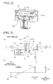
- the steering gear sets 7fL, 7fR are similar, and are configured as described below with reference to FIG. 2 for the left-front-wheel steering gear set 7fL.
- the left-front-wheel steering gear set 7fL is provided with a pinion 7pfL drivably coupled to the outer end of the left front wheel steering shaft 6fL, and a face gear 7ffL disposed on the kingpin axis Kp of the left front wheel 10fL and adapted so as to be capable of rotating about the axis.
- the pinion 7pfL is caused to engage with the face gear 7ffL so that the rotation of the steering shaft 6fL can be converted to a rotation of the face gear 7ffL about the kingpin axis Kp, and the left front wheel 10fL is coupled to the face gear 7ffL so as to be capable of being steered about the kingpin axis Kp.
- the face gear 7ffL is pressed against the pinion 7pfL by an elastic body such as a spring (not shown), and adapted to remove the backlash between the face gear 7ffL and the pinion 7pfL.
- an elastic body such as a spring (not shown)
- the left and right front wheels 10fL, 10fR use the steering wheel 1 and a power steering assist motor 3f for assisting the steering force from the steering wheel 1 as steering force sources.
- the output shaft of the assist motor 3f is coupled in an intersecting manner by an intersecting shaft gear 4f to the steering shaft 6fR of the right front wheel 10fR.
- a front-wheel differential gear set 5f is interposed between mutually adjacent ends of the left- and right-front-wheel steering shafts 6fL, 6fR on the inward side with respect to the vehicle width direction.
- the mutually adjacent ends of the left- and right-front-wheel steering shafts 6fL, 6fR are associated across the differential gear set 5f as follows.
- the front-wheel differential gear set 5f comprises a single-pinion-type planetary gear set (simple planetary gear set) 51f as shown in FIG. 3(a) .
- the single-pinion-type planetary gear set 51f comprises a sun gear 51sf, a ring gear 51 rf, and a carrier 51cf for rotatably supporting a pinion 51pf which engages with each of the gears.
- the sun gear 51sf is coupled to the steering shaft 6fR on the side at which the steering force from the steering wheel 1 is inputted.
- the ring gear 51rf is coupled to the steering shaft 6fL on the opposite side.
- the carrier 51cf is drivably coupled to a steering angle adjustment motor 52f through a reduction gear 53f.
- the arrows on the front wheel side in FIG. 1 are directions of rotation of the respective elements when the left and right front wheels 10fL, 10fR are steered to the right.
- the steering force from the steering wheel 1 after being amplified by the assist motor 3f, reaches the right front wheel 10fR through the intersecting shaft gear 4f, the steering shaft 6fR, and the steering gear set 7fR, and enables the right front wheel 10fR to be steered at a value corresponding to the steering angle of the steering wheel 1.
- the steering force on the steering shaft 6fR reaches, from the sun gear 51sf, the ring gear 51rf with the carrier 51cf acting as a reaction force receiver, then reaches the left front wheel 10fL through the steering shaft 6fL and the steering gear set 7fL, whereby the left front wheel 10fL can be steered.
- the steering angle adjustment motor 52f can be operated, whereby the rotation ratio of the steering shaft 6fL relative to the steering shaft 6fR can be arbitrarily changed, and the steering angle of the left front wheel 10fL relative to the steering angle of the right front wheel 10fR can be set as shown in FIG. 1 or otherwise arbitrarily set as described in detail further below.
- a steering sensor 2f for detecting the amount of operation (steering angle) and the speed of operation (steering speed) of the steering wheel 1 is provided to a steering column shaft which rotates with the steering wheel 1.
- the steering sensor 2f corresponding to the steering operation detection means of the present invention.
- the left and right rear wheels 10rL, 10rR are respectively provided with left- and right-rear-wheel steering shafts 6rL, 6rR extending inwards in the vehicle width direction from the wheels, and are steered by rotation of the left- and right-rear-wheel steering shafts 6rL, 6rR about the longitudinal axes.
- steering gear sets 7rL, 7rR (having gear ratios i rL , i rR ) for converting the rotation of the steering shafts 6rL, 6rR about the longitudinal axes into a rotation of the corresponding left and right rear wheels 10rL, 10rR about kingpin axes in assisting the steering in assisting the steering of the left and right rear wheels 10rL, 10rR.
- the left and right rear wheels 10rL, 10rR are respectively steerably coupled to outer ends, with respect to the vehicle width direction, of the steering shafts 6rL, 6rR with the steering gear sets 7rL, 7rR interposed therebetween.
- Each of the steering gear sets 7rL, 7rR are similar to the left-front-wheel steering gear set 7fL described above with reference to FIG. 2 .
- the left and right rear wheels 10rL, 10rR use a rear-wheel steering motor 3r as a steering force source.
- the output shaft of the rear-wheel steering motor 3r is drivably coupled to the steering shaft 6rR of the right rear wheel 10rR.
- a rear-wheel differential gear set 5r is interposed between mutually adjacent ends of the left- and right-rear-wheel steering shafts 6rL, 6rR on the inward side with respect to the vehicle width direction.
- the mutually adjacent ends of the left- and right-rear-wheel steering shafts 6rL, 6rR are linked across the rear-wheel differential gear set 5r as follows.
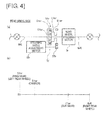
- the rear-wheel differential gear set 5r comprises a single-pinion-type planetary gear set (simple planetary gear set) 51r as shown in FIG. 4(a) .
- the single-pinion-type planetary gear set 51r comprises a sun gear 51sr, a ring gear 51rr, and a carrier 51cr for rotatably supporting a pinion 51pr which engages with each of the gears.
- the sun gear 51sr is coupled to the steering shaft 6rR on the side at which the steering force from the rear-wheel steering motor 3r is inputted.
- the ring gear 51rr is coupled to the steering shaft 6rL on the opposite side.
- the carrier 51cr is drivably coupled to a steering angle adjustment motor 52r through a reduction gear 53r.
- the steering force from the rear-wheel steering motor 3r reaches the right rear wheel 10rR through the steering shaft 6rR and the steering gear set 7rR, and enables the right front wheel 10rR to be steered at a value corresponding to the rotation angle of the rear-wheel steering motor 3r.
- the steering force on the steering shaft 6rR reaches, from the sun gear 51sr, the ring gear 51rr with the carrier 51cr acting as a reaction force receiver, then reaches the left rear wheel 10rL through the steering shaft 6rL and the steering gear set 7rL, whereby the left rear wheel 10rL can be steered.
- the steering angle adjustment motor 52r can be operated, whereby the rotation ratio of the steering shaft 6rL relative to the steering shaft 6rR can be arbitrarily changed, and the steering angle of the left rear wheel 10rL relative to the steering angle of the right rear wheel 10rR can be arbitrarily set.
- FIG. 1 shows a state in which neither of the left and right rear wheels 10rL, 10rR are being steered.
- FIG. 3(b) is a nomogram showing the rotation speed relationship between the members in the differential gear set 5f in an instance in which the rotation axes of the left and right front wheels 10fL, 10fR intersect the extension line of the rear axes of the left and right rear wheels 10rL, 10rR in a non-steered state as shown in FIG. 1 at the same point O as a result of the left front wheel 10fL being imparted, by the steering angle adjustment motor 52f in FIG. 3(a) through the differential gear set 5f, with a steering angle ⁇ different from the steering angle ⁇ of the right front wheel 10fR as shown in FIG. 1 .
- the rotation angular velocity ⁇ cf of the carrier 51cf is controlled by the steering angle adjustment motor 52f so that the rotation angular velocity ⁇ L2 of the left front wheel steering shaft 6fL satisfies the above relationship, whereby the left and right front wheels 10fL, 10fR can be steered as shown in FIG. 1 .
- FIG. 4(b) is a nomogram showing the rotation speed relationship between the members in the differential gear set 5r in an instance in which the rear-wheel steering motor 3r and the steering angle adjustment motor 52r in FIG. 4(a) are maintained in a non-operating state and the left and right rear wheels 10rL, 10rR are not steered together as in FIG. 1 .
- a brake for immobilizing the left-and right-rear-wheel steering shafts 6rL, 6rR so as to be incapable of rotating may be provided for such an instance.
- the maneuver mode shown in FIG. 1 is a two-wheel maneuver mode through steering of the left and right front wheels 10fL, 10fR only.
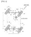
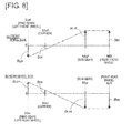
- FIGS. 6(a) and 6(b) are nomograms showing the rotation speed relationship between the members in the front-wheel-side differential gear set 5f (single-pinion-type planetary gear set 51f) and the rotation speed relationship between the members in the rear-wheel-side differential gear set 5r (single-pinion-type planetary gear set 51r), respectively, in an instance of the parallel movement maneuver mode shown in FIG. 5 .
- the steering angular velocity d ⁇ F of the left front wheel 10fL is obtained from expressions (4) and (5).
- the gear ratio of the left-front-wheel steering gear set 7fL is represented by i fL
- the sharp-turn mode shown in FIGS. 7 and 8 is a mode in which the left and right front wheels 10fL, 10fR. and the left and right rear wheels 10rL, 10rR are reverse-phase-steered so that the center of vehicle turn is positioned further forward from the extension line of the rear wheel axis by distance L R as shown in FIG. 7 , whereby the vehicle is made to perform a sharp turn.
- FIGS. 8(a) and 8(b) are nomograms showing the rotation speed relationship between the members in the front-wheel-side differential gear set 5f (single-pinion-type planetary gear set 51f) and the rotation speed relationship between the members in the rear-wheel-side differential gear set 5r (single-pinion-type planetary gear set 51r), respectively, in an instance of the sharp-turn mode shown in FIG. 7 .
- the steering angular velocity d ⁇ F of the left front wheel 10fL is obtained from expressions (9) and (12).
- the gear ratio of the left-front-wheel steering gear set 7fL is represented by i fL
- the rear wheel steering control in the sharp-turn mode will now be described with reference to the nomogram in FIG. 8(b) .
- the steering angular velocity d ⁇ R of the right rear wheel 10rR is obtained from expressions (10) and (12).
- the gear ratio of the right rear wheel steering gear set 7rR is represented by i rR
- the steering angular velocity d ⁇ R of the left rear wheel 10rL is obtained from expression (12).
- the gear ratio of the left rear wheel steering gear set 7rL is represented by i rL
- the pivot-turn mode shown in FIGS. 9 and 10 is a maneuver mode in which, as shown in FIG. 9 , the vehicle is caused to turn on the spot about a point at the center of the vehicle body in top view.
- the pivot-turn mode can be achieved by steering the left and right front wheels 10fL, 10fR and the left and right rear wheels 10rL, 10rR so that the respective rotational axes pass through the point at the center of the vehicle body as shown in FIG. 9 .
- each of the right front wheel steering angle ⁇ F , the left-front-wheel steering angle ⁇ F , the right rear wheel steering angle ⁇ R , and the left rear wheel steering angle ⁇ R is univocally determined from the tread W and the wheel base L.
- FIGS. 10(a) and 10(b) are nomograms showing the rotation speed relationship between the members in the front-wheel-side differential gear set 5f (single-pinion-type planetary gear set 51f) and the rotation speed relationship between the members in the rear-wheel-side differential gear set 5r (single-pinion-type planetary gear set 51r), respectively, in an instance of the pivot-turn mode shown in FIG. 9 .
- the left front steering shaft 6fL is caused to rotate in the same direction as the right front wheel steering shaft 6fR.
- a configuration is present so that the rotation ratio can be changed between the left- and right-front-wheel steering shafts 6fL, 6fR using the steering angle adjustment motor 52f through the corresponding differential gear set 5f, and the rotation ratio can be changed between the left- and right-rear-wheel steering shafts 6rL, 6rR using the rear-wheel steering angle adjustment motor 52r through the corresponding differential gear set 5r. Therefore, as described above with reference to FIGS.
- a steering system provided with a maneuver mode selection means (not shown) for the driver to select the maneuver mode for the vehicle automatically or by manual operation, a steering operation detection means 2f (see FIG. 1 ) for detecting the amount and speed of the steering operation, and a steering angle detection means (not shown) for detecting the steering angles of the left and right front wheels 10fL, 10fR and the left and right rear wheels 10rL, 10rR (not shown), in which an actuator control means (not shown) controls, on the basis of signals from the above means, the steering angle adjustment motor 52f and the steering angle adjustment motor 52r so as to achieve the selected maneuver mode while satisfying the Ackermann-Jeantaud relationship.
- a maneuver mode selection means for the driver to select the maneuver mode for the vehicle automatically or by manual operation
- a steering operation detection means 2f for detecting the amount and speed of the steering operation
- a steering angle detection means for detecting the steering angles of the left and right front wheels 10fL, 10fR and the left and right rear wheels 10rL, 10rR
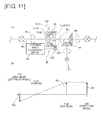
- FIG. 11a is a detailed drawing, similar to FIG. 3(a) , showing a steering angle adjustment differential gear set 5f of a front wheel steering system in a steering device representing a second embodiment of the present invention.
- the present embodiment is configured so that a lock mechanism 54 enabling two-directional braking is provided to the differential gear set 5f so that the carrier 51cf of the differential gear set 5f can be immobilized in both rotation directions.
- the steering device for the vehicle has otherwise a similar configuration as that described above with reference to FIG. 1 .
- the steering angle adjustment motor 52f does not function, and in order for the steering angle relationship between the left and right front wheels 10fL, 10fR to satisfy the aforementioned Ackermann-Jeantaud relationship represented in expression (1), it is necessary that the gear ratio (speed ratio) between the left- and right-front-wheel steering gear sets 7fL, 7fR be a variable speed ratio.
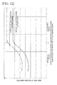
- variable speed ratio gear set having the gear ratio change characteristics shown in FIG. 12 is used for each of the left- and right-front-wheel steering gear sets 7fL, 7fR.
- FIG. 12 shows the gear ratio change characteristics of the left- and right-front-wheel steering gear sets 7fL, 7fR relative to the output-side rotation angle of the left- and right-front-wheel steering gear sets 7fL, 7fR, i.e., the left and right-front-wheel steering angle.
- a variable speed ratio is used such that from amongst the left- and right-front-wheel steering gear sets 7fL, 7fR, the steering gear set 7fR or 7fL on the outer-wheel side has a constant gear ratio and the steering gear set 7fR or 7fL on the inner-wheel side has a gear ratio satisfying expression (1).
- the lock mechanism 54 described above can be configured as shown, e.g., in FIGS. 13 and 14 .
- FIG. 13 is a schematic side view showing the lock mechanism 54 embedded into the front-wheel differential gear set 5f (single-pinion-type planetary gear set 51f), and FIG. 14 is a vertical cross-section front view of the lock mechanism 54.
- An inner ring 541 of the lock mechanism (two-directional brake) 54 is coupled to the carrier 51cf of the front-wheel differential gear set 5f (single-pinion-type planetary gear set 51f).
- An outer ring 542 of the lock mechanism (two-directional brake) 54 is fixed to a case of the front-wheel differential gear set 5f (single-pinion-type planetary gear set 51f).
- An inner circumferential rolling surface of the outer ring 542 is shaped as a regular polygon so as to function as a cam surface, and a plurality of rollers 543 are interposed between the inner circumferential rolling surface of the outer ring 542 and an outer circumferential surface of the inner ring 541.
- rollers 543 are held at regular intervals along the circumferential direction between the inner and outer circumferential cam surfaces by a spring 544 and a holder 545.
- An electromagnet 548 is provided in the axial direction of the holder 545 so as to face the holder 545.
- the electromagnet 548 when not energized, allows the holder 545 to rotate, and when energized, suctions an armature 546 integral with the holder 545 to an outer ring plate 547 and thereby immobilizes the holder 545 at a center position.
- the holder 545 While the electromagnet 548 is not energized and the holder 545 is capable of rotating, the holder 545 is able to rotate with the carrier 51cf, the gap between the inner and outer circumferential cam surfaces and the rollers 543 is eliminated, and the carrier 51cf is locked with regards to both rotations.
- the lock mechanism (two-directional brake) 54 may also be conversely configured so that the holder 545 is able to rotate when the electromagnet 548 is energized and the holder 545 is immobilized at the center position when the electromagnet 548 is not energized.
- a configuration is present so that the carrier 51cf of the differential gear set 5f can be immobilized using the lock mechanism 54 so that, in the two-wheel maneuver mode in which only the left and right front wheels 10fL, 10fR are steered, the lock mechanism 54 can be operated to immobilize the carrier 51cf of the differential gear set 5f, whereby the two-wheel maneuver mode can be realized while satisfying the Ackermann-Jeantaud relationship without relying on operation of the steering angle adjustment motor 52f.
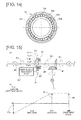
- FIG. 15(a) is a detailed drawing, similar to FIG. 3(a) , showing a steering angle adjustment differential gear set 5f of a front wheel steering system in a steering device representing a third embodiment of the present invention.
- the differential gear set 5f comprises a planetary gear set 51f, and a double-pinion planetary gear set is used as the planetary gear set 51f.
- the double-pinion planetary gear set is one in which the aforementioned pinion 51pf is replaced by a double pinion 51pfi, 51pfo engaging with each other.
- An inside pinion 51pfi is engaged with the sun gear 51sf, and an outside pinion 51pfo is engaged with the ring gear 51rf.
- the sun gear 51 sf is coupled to the inner end of the right front wheel steering shaft 6fR, as with the aforementioned embodiments.
- the carrier 5cf of the double pinion 51pfi, 51pfo is coupled to the left front wheel steering shaft 6fL.
- the steering angle adjustment motor 52f is drivably coupled to the ring gear 51rf through the reduction gear 53f.
- a lock mechanism 54 enabling two-directional braking is provided to the differential gear set 5f so that a configuration is present in which the ring gear 51rf of the differential gear set 5f can be immobilized in both rotation directions.
- the lock mechanism 54 is capable of locking the rotation of the ring gear 51rf as appropriate through the same principal as that described above with reference to FIGS. 13 and 14 .
- the outer ring of the lock mechanism 54 is coupled to the ring gear 51rf and the inner ring is fixed to the case of the differential gear set 5f.
- the steering device for the vehicle has otherwise the same configuration as that described above with reference to FIG. 1 .
- the arrows shown in FIG. 15(a) are directions of rotation of the respective axes when the front wheels are steered to the right.
- FIG. 15(b) The rotation speed relationship between the rotation members in the differential gear set 5f when the lock mechanism 54 is operating (i.e., when the ring gear 51rf is immobilized) is shown in FIG. 15(b) .
- the steering angle adjustment motor 52f does not function, and in order for the steering angle relationship between the left and right front wheels 10fL, 10fR to satisfy the aforementioned Ackermann-Jeantaud relationship represented in expression (1), it is necessary that the gear ratio (speed ratio) between the left- and right-front-wheel steering gear sets 7fL, 7fR be a variable speed ratio.
- the steering angle adjustment differential gear set 5f for the front wheel steering system comprises the double-pinion planetary gear set 51f, the teeth number ratio ⁇ (number of sun gear teeth/number of ring gear teeth) thereof can readily be made to approximate 0.5.
- the rotation angles ⁇ L2 , ⁇ L1 ( ⁇ R ) of the left- and right-front-wheel steering shafts 6fL, 6fR can be made even, and the gear ratios ⁇ i fR ( ⁇ R ) ⁇ , ⁇ i fL ( ⁇ L2 ) ⁇ of the front wheel steering gear sets 7fL, 7fR can also be made even.
- the front wheel steering gear sets 7fL, 7fR can thereby be made more compact, allowing the size of the steering device to be reduced.
- FIG. 16 is a detailed drawing, similar to FIG. 4(a) , showing a rear wheel steering system of the steering device according to a fourth embodiment of the present invention.
- the steering angle adjustment differential gear set 5r of the rear wheel steering system comprises a planetary gear set 51r, and a double-pinion planetary gear set is used as the planetary gear set 51r.
- the double-pinion planetary gear set is one in which the aforementioned pinion 51pr is replaced by a double pinion 51pri, 51pro engaging with each other.
- An inside pinion 51pri is engaged with the sun gear 51sr, and an outside pinion 51pro is engaged with the ring gear 51rr
- the sun gear 51 sr is coupled to the inner end of the right rear wheel steering shaft 6rR, as with the aforementioned embodiments.
- the carrier 51cr of the double pinion 51pri, 51pro is coupled to the left rear wheel steering shaft 6rL.
- the steering angle adjustment motor 52r is drivably coupled to the ring gear 51rr through the reduction gear 53r.
- the steering angle adjustment differential gear set 5f of the front wheel steering system comprises a double-pinion planetary gear set 51 f, as with the instance of the aforementioned third embodiment described above with reference to FIG. 15(a) .
- the lock mechanism 54 in FIG. 15(a) is not always required. The following description is given on the assumption that the lock mechanism 54 is in a non-operating state and the ring gear 51rf is not locked.
- FIGS. 17(a), 17(b) are nomograms showing the rotation speed relationship between the members in the front-wheel-side differential gear set 5f (double-pinion planetary gear set 51f shown in FIG. 15 ) and the rotation speed relationship between the members in the rear-wheel-side differential gear set 5r (double-pinion planetary gear set 51r shown in FIG. 16 ), respectively, in the parallel movement maneuver mode in which all of the left and right front wheels 10fL, 10fR and the left and right rear wheels 10rL, 10rR are similarly steered and the vehicle is moved in parallel in the direction in which all of the wheels are steered as shown in FIG. 5 .
- each of the front-wheel-side differential gear set 5f and the rear-wheel-side differential gear set 5r comprises a single-pinion-type planetary gear set
- the rotation of each of the steering angle adjustment motors 52f, 52r is controlled so that the aforementioned expression (4) is satisfied.
- the single-pinion-type planetary gear set shown in FIG. 4(a) may also be used as the rear-wheel-side differential gear set 5r.
- each of the steering angle adjustment motors 52f, 52r being controlled as described above results in the nomogram for the front-wheel-side differential gear set 5f shown in FIG. 17(a) and the nomogram for the rear-wheel-side differential gear set 5r shown in FIG. 17(b) being completely identical, and it being possible to steer all of the left and right front wheels 10fL, 10fR and the left and right rear wheels 10rL, 10rR in a similar manner and to move the vehicle in parallel in the direction in which all of the wheels are steered.
- FIGS. 18(a), 18(b) are nomograms showing the rotation speed relationship between the members in the front-wheel-side differential gear set 5f (double-pinion planetary gear set 51f shown in FIG. 15 ) and the rotation speed relationship between the members in the rear-wheel-side differential gear set 5r (double-pinion planetary gear set 51r shown in FIG. 16 ), respectively, in the sharp-turn mode in which the left and right front wheels 10fL, 10fR and the left and right rear wheels 10rL, 10rR are reverse-phase-steered so that the vehicle is made to perform a sharp turn about a center point positioned further forward from the extension line of the rear wheel axis by distance L R as shown in FIG. 7 .
- each of the front-wheel-side differential gear set 5f and the rear-wheel-side differential gear set 5r comprises a single-pinion-type planetary gear set
- the rotation of each of the steering angle adjustment motors 52f, 52r is controlled so that the aforementioned expressions (9) to (11) are satisfied.
- the single-pinion-type planetary gear set shown in FIG. 4(a) may also be used as the rear-wheel-side differential gear set 5r.
- each of the steering angle adjustment motors 52f, 52r being controlled as described above results in the nomogram for the front-wheel-side differential gear set 5f shown in FIG. 18(a) and the nomogram for the rear-wheel-side differential gear set 5r shown in FIG. 18(b) being completely symmetrical about the reference line representing a rotation speed of zero, and it being possible to reverse-phase-steer the left and right front wheels 10fL, 10fR and the left and right rear wheels 10rL, 10rR as shown as an example in FIG. 7 and cause the vehicle to perform a sharp turn.
- FIGS. 19(a) , 17(b) are nomograms showing the rotation speed relationship between the members in the front-wheel-side differential gear set 5f (double-pinion planetary gear set 51f shown in FIG. 15 ) and the rotation speed relationship between the members in the rear-wheel-side differential gear set 5r (double-pinion planetary gear set 51r shown in FIG. 16 ), respectively, in the pivot-turn mode in which the left and right front wheels 10fL, 10fR and the left and right rear wheels 10rL, 10rR are steered so that the respective rotational axes pass through the point at the center of the vehicle body, whereby the vehicle is caused to turn on the spot about the center of the vehicle body, as shown in FIG. 9 .
- each of the front-wheel-side differential gear set 5f and the rear-wheel-side differential gear set 5r comprises a single-pinion-type planetary gear set
- the rotation of each of the steering angle adjustment motors 52f, 52r is controlled so that the aforementioned expression (16) is satisfied.
- the single-pinion-type planetary gear set shown in FIG. 4(a) may also be used as the rear-wheel-side differential gear set 5r.
- each of the steering angle adjustment motors 52f, 52r being controlled as described above results in the nomogram for the front-wheel-side differential gear set 5f shown in FIG. 19(a) and the nomogram for the rear-wheel-side differential gear set 5r shown in FIG. 19(b) being shaped as rectangles that are completely symmetrical about the reference line representing a rotation speed of zero, and it being possible to steer the left and right front wheels 10fL, 10fR and the left and right rear wheels 10rL, 10rR as shown as an example in FIG. 9 .
- steering the left and right front wheels 10fL, 10fR and the left and right rear wheels 10rL, 10rR as described above in the parallel movement maneuver mode, the sharp-turn mode, or the pivot-turn mode makes it possible to realize each of the modes while satisfying the Ackermann-Jeantaud relationship and prevent the problems of uneven wear and squealing of the wheel tires from being generated in any of the modes.
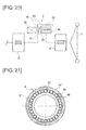
- FIGS. 20 and 21 show a steering column shaft of a steering device representing an example of a fifth embodiment of the present invention.
- This steering column is divided between the steering wheel 1 and the assist motor 3f, and a connecting/disconnecting clutch 8 functioning as a connecting/disconnecting means is interposed between the division sections, as shown in FIG. 20 .
- the connecting/disconnecting clutch 8 is concentrically provided with an inner ring 81 and an outer ring 82.
- the inner ring 81 is coupled to the column shaft division section on the side towards the steering wheel 1 and the outer ring 82 is coupled to the column shaft division section on the side towards the assist motor 3f by an outer ring plate 87.
- An inner circumferential rolling surface of the outer ring 82 is shaped as a regular polygon so as to function as a cam surface, and a plurality of rollers 83 are interposed between the inner circumferential rolling surface of the outer ring 82 and an outer circumferential surface of the inner ring 81.
- rollers 83 are held at regular intervals along the circumferential direction between the inner and outer circumferential cam surfaces by a spring 84 and a holder 85.
- An electromagnet 88 is provided in the axial direction of the holder 85 so as to face the holder 85.
- the electromagnet 88 when not energized, allows the holder 55 to rotate, and when energized, suctions an armature 86 integral with the holder 85 to an outer ring plate 87 and thereby immobilizes the holder 85 at a center position.
- the holder 85 While the electromagnet 88 is not energized and the holder 85 is capable of rotating, the holder 85 is able to rotate with the outer ring plate 87, the gap between the inner and outer circumferential cam surfaces and the rollers 83 is eliminated, the column shaft division portions are coupled to each other, and the rotation of the steering wheel 1 can be transmitted to the assist motor 3f.
- the steering device otherwise has a similar configuration to any of the first through fourth embodiments.
- the connecting/disconnecting clutch 8 is left disconnected while a maneuver mode unrelated to the operation of the steering wheel 1, such as the parallel movement maneuver mode (including a 90° lateral movement) such as that shown in FIG. 5 or the pivot-turn mode such as that shown in FIG. 9 , is enabled.
- a maneuver mode unrelated to the operation of the steering wheel 1 such as the parallel movement maneuver mode (including a 90° lateral movement) such as that shown in FIG. 5 or the pivot-turn mode such as that shown in FIG. 9 , is enabled.
- the connecting/disconnecting clutch 8 is disconnected by energization of the electromagnet 88 only when the pivot-turn mode or the 90° lateral movement mode, which are not used frequently, is enabled, making it possible to minimize the amount of power consumed by the energization and delivering a benefit in terms of energy efficiency.
- front-wheel-side differential gear set 5f and the rear-wheel-side differential gear set 5r both comprise a single-pinion-type planetary gear set or instances in which the front-wheel-side differential gear set 5f and the rear-wheel-side differential gear set 5r both comprise a double-pinion planetary gear set.
- one of the front-wheel-side differential gear set 5f and the rear-wheel-side differential gear set 5r to comprise a single-pinion-type planetary gear set and the other to comprise a double-pinion planetary gear set.
- steering gear sets 7fL, 7fR for the left and right front wheels prefferably be variable speed ratio gear and the steering gear sets 7rL, 7rR for the left and right rear wheels to be non-variable speed ratio gear for the following reason.
- the frequency of use of a maneuver mode employing only the rear-wheel side is extremely low; therefore, it is rare for the differential gear set 3r to be used in a locked state as in the front-wheel side.
- the rear-wheel side differential gear set 3r does not require a lock mechanism, and controlling of the left- and right-wheel steering angles can be performed using the steering angle adjustment motor 52r. Accordingly, the left- and right-rear-wheel steering gear sets 7rL, 7rR need not necessarily be variable speed ratio gear , and may be non-variable speed ratio gear.
- the size will be smaller than that of variable speed ratio gear, making it possible to reduce the size of the left- and right-rear-wheel steering gear sets 7rL, 7rR.
Landscapes
- Engineering & Computer Science (AREA)
- Chemical & Material Sciences (AREA)
- Combustion & Propulsion (AREA)
- Transportation (AREA)
- Mechanical Engineering (AREA)
- Physics & Mathematics (AREA)
- Mathematical Physics (AREA)
- Steering-Linkage Mechanisms And Four-Wheel Steering (AREA)
- Power Steering Mechanism (AREA)
- Steering Control In Accordance With Driving Conditions (AREA)
Abstract
Description
- The present invention relates to an improvement proposal regarding a steering device in which left and right front wheels and left and right rear wheels are steered by rotation, about the longitudinal axis, of a steering shaft provided to each of the wheels so as to extend inwards along the vehicle width direction.
- Steering devices of such type are able to select, other than the common two-wheel maneuver mode through steering of left and right front wheels only, a variety of maneuver modes such as a sharp-turn mode in which the vehicle is made to perform a sharp turn by reverse-phase-steering the left and right front wheels and the left and right rear wheels, a pivot-turn (on-the-spot-turn) mode in which the vehicle is turned at the present position, or a parallel movement maneuver mode in which all of the left and right front wheels and the left and right rear wheels are similarly steered, and are useful for electric vehicles for which large steering actions are a strong-point.
- Steering devices of such description proposed in the past include, e.g., the device disclosed in Patent Citation 1.
- In this proposed technique, there are provided a forward/reverse switching mechanism for switching the rotation direction between the left- and right-wheel steering shafts, and a steering gear set for converting the rotation of the left- and right-wheel steering shafts into a rotation about left- and right-wheel kingpin axes in assisting with steering of the left and right wheels, the steering gear set comprising variable speed ratio gears, and non-circular gears in which the pitch curve is changed in two stages are used as the variable speed ratio gears.
- According to this steering device, it is possible to operate the forward/reverse switching mechanism to select the required vehicle maneuver mode, i.e., one of the above-mentioned two-wheel maneuver mode, sharp-turn mode, pivot-turn mode, and parallel movement maneuver mode.
- Patent Document 1: Japanese Laid-Open Patent Application No.
2007-022159 - However, in the conventional steering device proposed in Patent Citation 1, the pitch curve of the steering gear set is set so that the center of vehicle turn is located at two locations, i.e., the extension line of the rear wheel axis or the extension line, in the vehicle width direction, passing through the center of the wheel base. Therefore, a problem is presented in that when an attempt is made to set the center of vehicle turn to an arbitrary position, the steering angle of the left and right front wheels and the steering angle of the left and right rear wheels do not satisfy the Ackermann-Jeantaud relationship, and uneven wear and squealing of the wheel tires occur.
- When an attempt is made to perform a sharp turn through large-steering-angle steering of left and right front wheels only, since the pitch curve of the steering gear set used for large steering of the front wheels is set as described below, i.e., the pitch curve of the steering gear set is set so that the center of vehicle turn is positioned on the extension line, in the vehicle width direction, passing through the center of the wheel base on the assumption that the rear wheels are also steered, the turning angle of the left and right front wheels no longer satisfies the Ackermann-Jeantaud relationship, and uneven wear and squealing of the wheel tires occur.
- If the turning angle of the left and right front wheels is made to satisfy the Ackermann-Jeantaud relationship in order to solve this problem, a problem is presented in that the steering angle of the left and right front wheels is restricted, and a result, the desired sharp turn is prevented from being realized.
- On the basis of a recognition of the fact that conventionally, since the rotation ratio is fixed between left and right steering shafts, when the wheels are steered so as to set the center of vehicle turn to an arbitrary position in order to realize a variety of maneuver modes, the Ackermann-Jeantaud relationship is no longer satisfied and the above problems of uneven wear and squealing of wheel tires are generated, an object of the present invention is to propose a steering device in which the rotation ratio can be changed between the left and right steering shafts and the center of vehicle turn can be set to an arbitrary position while satisfying the Ackermann-Jeantaud relationship, whereby the various maneuver modes can be realized without the above problems of uneven wear and squealing of the wheel tires being generated.
- In order to achieve the above objective, a steering device according to the present invention is configured as follows. First, a description will be given for a steering device that is the premise of the present invention. The steering device that is the premise of the present invention is a steering device for a vehicle in which left and right front wheels and left and right rear wheels are steered through a rotation, about the longitudinal axis, of a steering shaft provided to each wheel so as to extend inwards along the vehicle width direction.
- The present invention is characterized in a configuration of a steering device of such description in which:
- a steering force source for transmitting a steering force in correspondence with a steering operation performed by a driver is provided individually to one of the left- and right-front-wheel steering shaft and to one of the left- and right-rear-wheel steering shaft;
- a differential gear set is interposed respectively between mutually adjacent ends of the left- and right-front-wheel steering shafts and between mutually adjacent ends of the left- and right-rear-wheel steering shafts; and
- two rotation elements of each of the differential gear sets are coupled respectively to corresponding mutually adjacent ends of the left- and right-front-wheel steering shafts and mutually adjacent ends of left- and right-rear-wheel steering shafts, and a corresponding front-wheel steering angle adjustment actuator and rear-wheel steering angle adjustment actuator are drivably coupled to a remaining rotation element of each of the differential gear sets.
- In the steering device of the present invention, it is possible to change the rotation ratio between left- and right-front-wheel steering shafts using the front-wheel steering angle adjustment actuator through the corresponding differential gear set, and to change the rotation ratio between left- and right-rear-wheel steering shafts using the rear-wheel steering angle adjustment actuator through the corresponding differential gear set.
- Therefore, it is possible to steer the left and right front wheels and the left and right rear wheels in a manner in which the center of vehicle turn can be set to an arbitrary position while satisfying the Ackermann-Jeantaud relationship, and to achieve a variety of maneuver modes without the problems of uneven wear and squealing of the wheel tires being generated.
-
- [
FIG. 1 ] is a schematic plan view in which front- and rear-wheel steering systems of an electric vehicle provided with a steering device representing a first embodiment of the present invention are shown for an instance in which a two-wheel maneuver mode in which only the left and right front wheels are steered is selected; - [
FIG. 2 ] is a main part cutaway perspective view showing a wheel-steering gear set for the left front wheel as a representative of a wheel-steering gear set in the steering device inFIG. 1 ; - [
FIG. 3 ] shows the front-wheel steering system in the steering device ofFIG. 1 , whereFIG. 3(a) is an outline diagram schematically showing the main parts of the front-wheel steering system andFIG. 3(b) is a nomogram showing the rotation speed relationship between members in the steering angle adjustment differential gear set in the front-wheel steering system in an instance in which the left and right front wheels are steered as shown inFIG. 1 ; - [
FIG. 4 ] shows the rear-wheel steering system in the steering device ofFIG. 1 , whereFIG. 4(a) is an outline diagram schematically showing the main parts of the rear-wheel steering system andFIG. 4(b) is a nomogram showing the rotation speed relationship between members in the steering angle adjustment differential gear set in the rear-wheel steering system in an instance in which the left and right rear wheels are in a non-steering state as shown inFIG. 1 ; - [
FIG. 5 ] is a schematic plan view in which front- and rear-wheel steering systems of an electric vehicle provided with the steering device representing the first embodiment of the present invention shown inFIG. 1 are shown for an instance in which a parallel movement maneuver mode, in which all of the left and right front wheels and the left and right rear wheels are similarly steered, whereby the vehicle moves in parallel, is enabled; - [
FIG. 6 ] shows nomograms showing the rotation speed relationship between members in the front-wheel steering angle adjustment differential gear set and the rotation speed relationship between members in the rear-wheel steering angle adjustment differential gear set when the parallel movement maneuver mode shown inFIG. 5 is enabled, whereFIG. 6(a) is a nomogram for the front-wheel steering angle adjustment differential gear set in an instance in which the left and right front wheels are steered as shown inFIG. 5 andFIG. 6(b) is a nomogram for the rear-wheel steering angle adjustment differential gear set in an instance in which the left and right rear wheels are steered as shown inFIG. 5 ; - [
FIG. 7 ] is a schematic plan view in which front- and rear-wheel steering systems of an electric vehicle provided with the steering device representing the first embodiment of the present invention shown inFIG. 1 are shown for an instance in which a sharp-turn mode, in which the left and right front wheels and the left and right rear wheels are reverse-phase-steered and the vehicle is thereby caused to perform a sharp turn, is enabled; - [
FIG. 8 ] shows nomograms showing the rotation speed relationship between members in the front-wheel steering angle adjustment differential gear set and the rotation speed relationship between members in the rear-wheel steering angle adjustment differential gear set when the sharp-turn mode shown inFIG. 7 is enabled, whereFIG. 8(a) is a nomogram for the front-wheel steering angle adjustment differential gear set in an instance in which the left and right front wheels are steered as shown inFIG. 7 andFIG. 8(b) is a nomogram for the rear-wheel steering angle adjustment differential gear set in an instance in which the left and right rear wheels are steered as shown inFIG. 7 ; - [
FIG. 9 ] is a schematic plan view in which front- and rear-wheel steering systems of an electric vehicle provided with the steering device representing the first embodiment of the present invention shown inFIG. 1 are shown for an instance in which a pivot-turn mode, in which the vehicle is turned at the present position, is enabled; - [
FIG. 10 ] shows nomograms showing the rotation speed relationship between members in the front-wheel steering angle adjustment differential gear set and the rotation speed relationship between members in the rear-wheel steering angle adjustment differential gear set when the pivot-turn mode shown inFIG. 9 is enabled, whereFIG. 10(a) is a nomogram for the front-wheel steering angle adjustment differential gear set in an instance in which the left and right front wheels are steered as shown inFIG. 9 andFIG. 10(b) is a nomogram for the rear-wheel steering angle adjustment differential gear set in an instance in which the left and right rear wheels are steered as shown inFIG. 9 ; - [
FIG. 11 ] shows the front-wheel steering system in a steering device representing a second embodiment of the present invention, whereFIG. 11(a) is an outline diagram schematically showing the main parts of the front-wheel steering system including the front-wheel steering angle adjustment differential gear set, andFIG. 11(b) is a nomogram showing the rotation speed relationship between members in the front-wheel steering angle adjustment differential gear set in an instance in which the two-wheel maneuver mode shown inFIG. 1 , in which only the left and right front wheels are steered, is enabled; - [
FIG. 12 ] is a gear ratio change characteristic diagram showing how the gear ratios of the left- and right-front-wheel steering gear sets in the steering device representing the second embodiment change with the left- and right-front-wheel steering angles; - [
FIG. 13 ] is an outline diagram schematically showing, in detail, a lock mechanism of the front-wheel steering angle adjustment differential gear set shown inFIG. 11(a) ; - [
FIG. 14 ] is a vertical cross-section front view showing the lock mechanism of the front-wheel steering angle adjustment differential gear set shown in detail inFIG. 13 ; - [
FIG. 15 ] shows the front-wheel steering system in a steering device representing a third embodiment of the present invention, whereFIG. 15(a) is an outline diagram schematically showing the main parts of the front-wheel steering system including the front-wheel steering angle adjustment differential gear set, andFIG. 15(b) is a nomogram showing the rotation speed relationship between members in the front-wheel steering angle adjustment differential gear set in an instance in which the lock mechanism of the front-wheel steering angle adjustment differential gear set is operating; - [
FIG. 16 ] is outline diagram schematically showing the main parts of the rear-wheel steering system including the rear-wheel steering angle adjustment differential gear set in the steering device representing a fourth embodiment of the present invention; - [
FIG. 17 ] shows nomograms for the front-wheel steering angle adjustment differential gear set and the rear-wheel steering angle adjustment differential gear set of the steering device representing the fourth embodiment of the present invention provided with the rear-wheel steering system shown inFIG. 16 when the parallel movement maneuver mode is enabled, whereFIG. 17(a) is a nomogram for the front-wheel steering angle adjustment differential gear set andFIG. 17(b) is a nomogram for the rear-wheel steering angle adjustment differential gear set; - [
FIG. 18 ] shows nomograms for the front-wheel steering angle adjustment differential gear set and the rear-wheel steering angle adjustment differential gear set of the steering device representing the fourth embodiment of the present invention provided when the sharp-turn mode is enabled, whereFIG. 18(a) is a nomogram for the front-wheel steering angle adjustment differential gear set andFIG. 18(b) is a nomogram for the rear-wheel steering angle adjustment differential gear set; - [
FIG. 19 ] shows nomograms for the front-wheel steering angle adjustment differential gear set and the rear-wheel steering angle adjustment differential gear set of the steering device representing the fourth embodiment of the present invention provided when the pivot-turn mode is enabled, whereFIG. 19(a) is a nomogram for the front-wheel steering angle adjustment differential gear set andFIG. 19(b) is a nomogram for the rear-wheel steering angle adjustment differential gear set; - [
FIG. 20 ] is an outline diagram schematically showing the steering column shaft portion of the front-wheel steering system in the steering device representing a fifth embodiment of the present invention; and - [
FIG. 21 ] is a vertical cross-section front view showing, in detail, the connection/disconnection clutch provided to the steering column shaft shown inFIG. 20 . -
- 1
- Steering wheel
- 2f
- Steering sensor (steering operation detection means)
- 3f
- Assist motor (steering force source)
- 3r
- Rear-wheel steering motor (steering force source)
- 4f
- Intersecting shaft gear
- 5f, 5r
- Steering angle adjustment differential gear set
- 6fL, 6fR, 6rL, 6rR
- Steering shaft
- 7fL, 7fR, 7rL, 7rR
- Steering gear set
- 8
- Connection/disconnection clutch (steering force connection/disconnection means)
- 10fL, 10fR
- Left and right front wheels
- 10rL, 10rR
- Left and right rear wheels
- 52f, 52r
- Steering angle adjustment motor
- 54
- Lock mechanism
- Embodiments of the present invention will now be described with reference to the accompanying drawings.
-
FIG. 1 is a schematic plan view showing front- and rear-wheel steering systems of an electric vehicle provided with a steering device corresponding to a first embodiment of the present invention. - The electric vehicle in
FIG. 1 is provided with left and right front wheels 10fL, 10fR and left and right rear wheels 10rL, 10rR, and is guided by all of the wheels being steered in correspondence with an operation (steering amount and steering speed) performed on asteering wheel 1. -
FIG. 1 shows the state in which only the left and right front wheels 10fL, 10fR are steered and the electric vehicle is capable of turning about a point O located on an extension line of the axes of the left and right rear wheels 10rL, 10rR. - First, the steering system for the left and right front wheels 10fL, 10fR will be described below.
- The left and right front wheels 10fL, 10fR are respectively provided with left-and right-front-wheel steering shafts 6fL, 6fR extending inwards in the vehicle width direction from the wheels, and are steered by rotation, about the longitudinal axes of the left-and right-front-wheel steering shafts 6fL, 6fR.
- Therefore, there are provided steering gear sets 7fL, 7fR (having gear ratios ifL, ifR) for converting the rotation of the steering shafts 6fL, 6fR about the longitudinal axes into a rotation of the corresponding left and right front wheels 10fL, 10fR. about kingpin axes in assisting with the steering of the left and right front wheels 10fL, 10fR. The left and right front wheels 10fL, 10fR are respectively steerably coupled to outer ends, with respect to the vehicle width direction, of the steering shafts 6fL, 6fR with the steering gear sets 7fL, 7fR interposed therebetween.
- The steering gear sets 7fL, 7fR are similar, and are configured as described below with reference to
FIG. 2 for the left-front-wheel steering gear set 7fL. - The left-front-wheel steering gear set 7fL is provided with a pinion 7pfL drivably coupled to the outer end of the left front wheel steering shaft 6fL, and a face gear 7ffL disposed on the kingpin axis Kp of the left front wheel 10fL and adapted so as to be capable of rotating about the axis.
- The pinion 7pfL is caused to engage with the face gear 7ffL so that the rotation of the steering shaft 6fL can be converted to a rotation of the face gear 7ffL about the kingpin axis Kp, and the left front wheel 10fL is coupled to the face gear 7ffL so as to be capable of being steered about the kingpin axis Kp.
- The face gear 7ffL is pressed against the pinion 7pfL by an elastic body such as a spring (not shown), and adapted to remove the backlash between the face gear 7ffL and the pinion 7pfL.
- The left and right front wheels 10fL, 10fR use the
steering wheel 1 and a power steering assistmotor 3f for assisting the steering force from thesteering wheel 1 as steering force sources. The output shaft of theassist motor 3f is coupled in an intersecting manner by an intersectingshaft gear 4f to the steering shaft 6fR of the right front wheel 10fR. - A front-wheel differential gear set 5f is interposed between mutually adjacent ends of the left- and right-front-wheel steering shafts 6fL, 6fR on the inward side with respect to the vehicle width direction. The mutually adjacent ends of the left- and right-front-wheel steering shafts 6fL, 6fR are associated across the
differential gear set 5f as follows. - The front-wheel differential gear set 5f comprises a single-pinion-type planetary gear set (simple planetary gear set) 51f as shown in
FIG. 3(a) . The single-pinion-type planetary gear set 51f comprises a sun gear 51sf, aring gear 51 rf, and a carrier 51cf for rotatably supporting a pinion 51pf which engages with each of the gears. The sun gear 51sf is coupled to the steering shaft 6fR on the side at which the steering force from thesteering wheel 1 is inputted. The ring gear 51rf is coupled to the steering shaft 6fL on the opposite side. The carrier 51cf is drivably coupled to a steeringangle adjustment motor 52f through areduction gear 53f. - The arrows on the front wheel side in
FIG. 1 are directions of rotation of the respective elements when the left and right front wheels 10fL, 10fR are steered to the right. - According to the above front wheel steering system shown in
FIGS. 1 and3(a) , the steering force from thesteering wheel 1, after being amplified by theassist motor 3f, reaches the right front wheel 10fR through the intersectingshaft gear 4f, the steering shaft 6fR, and the steering gear set 7fR, and enables the right front wheel 10fR to be steered at a value corresponding to the steering angle of thesteering wheel 1. - Meanwhile, the steering force on the steering shaft 6fR reaches, from the sun gear 51sf, the ring gear 51rf with the carrier 51cf acting as a reaction force receiver, then reaches the left front wheel 10fL through the steering shaft 6fL and the steering gear set 7fL, whereby the left front wheel 10fL can be steered.
- At this time, the steering
angle adjustment motor 52f can be operated, whereby the rotation ratio of the steering shaft 6fL relative to the steering shaft 6fR can be arbitrarily changed, and the steering angle of the left front wheel 10fL relative to the steering angle of the right front wheel 10fR can be set as shown inFIG. 1 or otherwise arbitrarily set as described in detail further below. - In order to perform a control when the rotation ratio of the steering shaft 6fL relative to the steering shaft 6fR is changed, a
steering sensor 2f for detecting the amount of operation (steering angle) and the speed of operation (steering speed) of thesteering wheel 1 is provided to a steering column shaft which rotates with thesteering wheel 1. - Therefore, the
steering sensor 2f corresponding to the steering operation detection means of the present invention. - Next, the steering system for the left and right rear wheels 10rL, 10rR will be described below.
- The left and right rear wheels 10rL, 10rR are respectively provided with left- and right-rear-wheel steering shafts 6rL, 6rR extending inwards in the vehicle width direction from the wheels, and are steered by rotation of the left- and right-rear-wheel steering shafts 6rL, 6rR about the longitudinal axes.
- Therefore, there are provided steering gear sets 7rL, 7rR (having gear ratios irL, irR) for converting the rotation of the steering shafts 6rL, 6rR about the longitudinal axes into a rotation of the corresponding left and right rear wheels 10rL, 10rR about kingpin axes in assisting the steering in assisting the steering of the left and right rear wheels 10rL, 10rR. The left and right rear wheels 10rL, 10rR are respectively steerably coupled to outer ends, with respect to the vehicle width direction, of the steering shafts 6rL, 6rR with the steering gear sets 7rL, 7rR interposed therebetween. Each of the steering gear sets 7rL, 7rR are similar to the left-front-wheel steering gear set 7fL described above with reference to
FIG. 2 . - The left and right rear wheels 10rL, 10rR use a rear-
wheel steering motor 3r as a steering force source. The output shaft of the rear-wheel steering motor 3r is drivably coupled to the steering shaft 6rR of the right rear wheel 10rR. - A rear-wheel differential gear set 5r is interposed between mutually adjacent ends of the left- and right-rear-wheel steering shafts 6rL, 6rR on the inward side with respect to the vehicle width direction. The mutually adjacent ends of the left- and right-rear-wheel steering shafts 6rL, 6rR are linked across the rear-wheel
differential gear set 5r as follows. - The rear-wheel differential gear set 5r comprises a single-pinion-type planetary gear set (simple planetary gear set) 51r as shown in
FIG. 4(a) . The single-pinion-type planetary gear set 51r comprises a sun gear 51sr, a ring gear 51rr, and a carrier 51cr for rotatably supporting a pinion 51pr which engages with each of the gears. - The sun gear 51sr is coupled to the steering shaft 6rR on the side at which the steering force from the rear-
wheel steering motor 3r is inputted. The ring gear 51rr is coupled to the steering shaft 6rL on the opposite side. The carrier 51cr is drivably coupled to a steeringangle adjustment motor 52r through areduction gear 53r. - According to the above rear wheel steering system shown in
FIGS. 1 and4(a) , the steering force from the rear-wheel steering motor 3r reaches the right rear wheel 10rR through the steering shaft 6rR and the steering gear set 7rR, and enables the right front wheel 10rR to be steered at a value corresponding to the rotation angle of the rear-wheel steering motor 3r. - Meanwhile, the steering force on the steering shaft 6rR reaches, from the sun gear 51sr, the ring gear 51rr with the carrier 51cr acting as a reaction force receiver, then reaches the left rear wheel 10rL through the steering shaft 6rL and the steering gear set 7rL, whereby the left rear wheel 10rL can be steered.
- At this time, the steering
angle adjustment motor 52r can be operated, whereby the rotation ratio of the steering shaft 6rL relative to the steering shaft 6rR can be arbitrarily changed, and the steering angle of the left rear wheel 10rL relative to the steering angle of the right rear wheel 10rR can be arbitrarily set. -
FIG. 1 shows a state in which neither of the left and right rear wheels 10rL, 10rR are being steered. -
FIG. 3(b) is a nomogram showing the rotation speed relationship between the members in the differential gear set 5f in an instance in which the rotation axes of the left and right front wheels 10fL, 10fR intersect the extension line of the rear axes of the left and right rear wheels 10rL, 10rR in a non-steered state as shown inFIG. 1 at the same point O as a result of the left front wheel 10fL being imparted, by the steeringangle adjustment motor 52f inFIG. 3(a) through the differential gear set 5f, with a steering angle β different from the steering angle α of the right front wheel 10fR as shown inFIG. 1 . - If the tread of the vehicle is represented by W and the wheel base is represented by L as shown in
FIG. 1 , the relationship between the steering angles α, β of the inner and outer wheels 10fR, 10fL is represented, from the Ackermann-Jeantaud relationship, by the following expression:
- When the right front wheel steering shaft 6fR rotates at an angular velocity θR, if the gear ratio of the steering gear set 7fR is represented by ifR, the steering angle velocity dα of the right front wheel 10fR (inner wheel in
FIG. 1 ) is:
- From expressions (1) and (2), the steering angle velocity dβ of the left front wheel 10fL (outer wheel in
FIG. 1 ) satisfying the Ackermann-Jeantaud relationship when the steering angle velocity of the right front wheel 10fR. (inner wheel inFIG. 1 ) is dα. When the gear ratio of the left-front-wheel steering gear set 7fL is ifL, the rotation angular velocity θL2 of the left front wheel steering shaft 6fL can be obtained from the following expression:
- The minus sign on the right side of the above expression (3) signifies that the left front wheel steering shaft 6fL is caused to rotate in the opposite direction to the right front wheel steering shaft 6fR.
- The rotation angular velocity θcf of the carrier 51cf is controlled by the steering
angle adjustment motor 52f so that the rotation angular velocity θL2 of the left front wheel steering shaft 6fL satisfies the above relationship, whereby the left and right front wheels 10fL, 10fR can be steered as shown inFIG. 1 . -
FIG. 4(b) is a nomogram showing the rotation speed relationship between the members in the differential gear set 5r in an instance in which the rear-wheel steering motor 3r and the steeringangle adjustment motor 52r inFIG. 4(a) are maintained in a non-operating state and the left and right rear wheels 10rL, 10rR are not steered together as inFIG. 1 . - In this instance, the left and right rear wheels 10rL, 10rR are not steered; therefore, the angular velocity of each of the rotation members in the differential gear set 5r is zero as shown in
FIG. 4(b) . - Although not shown, it shall be apparent that a brake for immobilizing the left-and right-rear-wheel steering shafts 6rL, 6rR so as to be incapable of rotating may be provided for such an instance.
- As is clear from the above description, the maneuver mode shown in
FIG. 1 is a two-wheel maneuver mode through steering of the left and right front wheels 10fL, 10fR only. However, in the present embodiment, it is possible to select: - a parallel movement maneuver mode in which all of the left and right front wheels 10fL, 10fR and the left and right rear wheels 10rL, 10rR are similarly steered and the vehicle is moved in parallel in the direction in which all of the wheels are steered as shown in
FIGS. 5 and6 ; - a sharp turn mode in which the vehicle is made to perform a sharp turn by reverse-phase-steering the left and right front wheels 10fL, 10fR and the left and right rear wheels 10rL, 10rR as shown in
FIGS. 7 and8 ; or - a pivot-turn (on-the-spot-turn) mode in which the vehicle is turned at the present position by steering the left and right front wheels 10fL, 10fR and the left and right rear wheels 10rL, 10rR as shown in
FIGS. 9 and10 . - The parallel movement maneuver mode will now be described with reference to
FIGS. 5 and6 . - As shown in
FIG. 5 , when the steering angle of the left and right front wheels 10fL, 10fR is βF and αF, respectively, and the steering angle of the left and right rear wheels 10rL, 10rR is βR and αR, respectively, in the parallel movement maneuver mode, the following relationship is true:
-
FIGS. 6(a) and 6(b) are nomograms showing the rotation speed relationship between the members in the front-wheel-side differential gear set 5f (single-pinion-type planetary gear set 51f) and the rotation speed relationship between the members in the rear-wheel-side differential gear set 5r (single-pinion-type planetary gear set 51r), respectively, in an instance of the parallel movement maneuver mode shown inFIG. 5 . - The front wheel steering control in the parallel movement maneuver mode will now be described with reference to the nomogram in
FIG. 6(a) . - When the right front wheel steering shaft 6fR rotates at an angular velocity of θRF, and the gear ratio of the right front wheel steering gear set 7fR is represented by ifR, the steering angular velocity dαF of the right front wheel 10fR is represented by the following expression:

- The steering angular velocity dβF of the left front wheel 10fL is obtained from expressions (4) and (5). When the gear ratio of the left-front-wheel steering gear set 7fL is represented by ifL, the rotation angular velocity θL2F of the left front wheel steering shaft 6fL is obtained from the following expression:

- Controlling the rotation angular velocity θcf of the
carrier 51 cf using the steeringangle adjustment motor 52f so that the rotation angular velocity θL2F of the left front wheel steering shaft 6fL satisfies the above relationship makes it possible to steer the left and right front wheels 10fL, 10fR as shown inFIG. 5 . - The rear wheel steering control in the parallel movement maneuver mode will now be described with reference to the nomogram in
FIG. 6(b) . When the gear ratio of the right rear wheel steering gear set 7rR is represented by irR, the angular velocity θRR of the right rear wheel steering shaft 6rR is represented by the following expression:
- Controlling the rotation speed of the rear-
wheel steering motor 3r so that the angular velocity θRR of the right rear wheel steering shaft 6rR satisfies the above relationship makes it possible to steer the right rear wheel 10rR as shown inFIG. 5 . - When the gear ratio of the left rear wheel steering gear set 7rL is represented by irL, the rotation angular velocity θL2R of the left rear wheel steering shaft 6rL is obtained from the following expression.

- Controlling the rotation angular velocity θCR of the carrier 51cr using the steering
angle adjustment motor 52r so that the θL2R of the left rear wheel steering shaft 6rL satisfies the above relationship makes it possible to steer the left rear wheel 10rL as shown inFIG. 5 . - The sharp-turn mode will now be described with reference to
FIGS. 7 and8 . - The sharp-turn mode shown in
FIGS. 7 and8 is a mode in which the left and right front wheels 10fL, 10fR. and the left and right rear wheels 10rL, 10rR are reverse-phase-steered so that the center of vehicle turn is positioned further forward from the extension line of the rear wheel axis by distance LR as shown inFIG. 7 , whereby the vehicle is made to perform a sharp turn. - From the Ackermann-Jeantaud relationship, the right front wheel steering angle αF, the left-front-wheel steering angle βF, the right rear wheel steering angle αR, and the left rear wheel steering angle βR are represented by the following expressions:



-
FIGS. 8(a) and 8(b) are nomograms showing the rotation speed relationship between the members in the front-wheel-side differential gear set 5f (single-pinion-type planetary gear set 51f) and the rotation speed relationship between the members in the rear-wheel-side differential gear set 5r (single-pinion-type planetary gear set 51r), respectively, in an instance of the sharp-turn mode shown inFIG. 7 . - The front wheel steering control in the sharp-turn mode will now be described with reference to the nomogram in
FIG. 8(a) . When the right front wheel steering shaft 6fR rotates at an angular velocity of θRF, and the gear ratio of the right front wheel steering gear set 7fR is represented by ifR, the steering angular velocity dαF of the right front wheel 10fR. is represented by the following expression:
- The steering angular velocity dβF of the left front wheel 10fL is obtained from expressions (9) and (12). When the gear ratio of the left-front-wheel steering gear set 7fL is represented by ifL, the rotation angular velocity θL2F of the left front wheel steering shaft 6fL is obtained from the following expression:

- Controlling the rotation angular velocity θcf of the
carrier 51 cf using the steeringangle adjustment motor 52f so that the rotation angular velocity θL2F of the left front wheel steering shaft 6fL satisfies the above relationship makes it possible to steer the left and right front wheels 10fL, 10fR as shown inFIG. 7 . - The rear wheel steering control in the sharp-turn mode will now be described with reference to the nomogram in
FIG. 8(b) . The steering angular velocity dαR of the right rear wheel 10rR is obtained from expressions (10) and (12). When the gear ratio of the right rear wheel steering gear set 7rR is represented by irR, the angular velocity θRR of the right rear wheel steering shaft 6rR is represented by the following expression:
- Controlling the rotation speed of the rear-
wheel steering motor 3r so that the angular velocity θRR of the right rear wheel steering shaft 6rR satisfies the above relationship makes it possible to steer the right rear wheel 10rR as shown inFIG. 7 . - Meanwhile, the steering angular velocity dβR of the left rear wheel 10rL is obtained from expression (12). When the gear ratio of the left rear wheel steering gear set 7rL is represented by irL, the rotation angular velocity θL2R of the left rear wheel steering shaft 6rL is obtained from the following expression:

- Controlling the rotation angular velocity θCR of the carrier 51cr using the steering
angle adjustment motor 52r so that the θL2R of the left rear wheel steering shaft 6rL satisfies the above relationship makes it possible to steer the left rear wheel 10rL as shown inFIG. 7 . - The pivot-turn (on-the-spot-turn) mode will now be described with reference to
FIGS. 9 and10 . - The pivot-turn mode shown in
FIGS. 9 and10 is a maneuver mode in which, as shown inFIG. 9 , the vehicle is caused to turn on the spot about a point at the center of the vehicle body in top view. The pivot-turn mode can be achieved by steering the left and right front wheels 10fL, 10fR and the left and right rear wheels 10rL, 10rR so that the respective rotational axes pass through the point at the center of the vehicle body as shown inFIG. 9 . - From the Ackermann-Jeantaud relationship, the right-front-wheel steering angle αF, the left-front-wheel steering angle βF, the right rear wheel steering angle αR, and the left rear wheel steering angle βR shown in
FIG. 9 are represented by the following expression:
- In other words, each of the right front wheel steering angle αF, the left-front-wheel steering angle βF, the right rear wheel steering angle αR, and the left rear wheel steering angle βR is univocally determined from the tread W and the wheel base L.
-
FIGS. 10(a) and 10(b) are nomograms showing the rotation speed relationship between the members in the front-wheel-side differential gear set 5f (single-pinion-type planetary gear set 51f) and the rotation speed relationship between the members in the rear-wheel-side differential gear set 5r (single-pinion-type planetary gear set 51r), respectively, in an instance of the pivot-turn mode shown inFIG. 9 . - The front wheel steering control in the pivot-turn mode will now be described with reference to the nomogram in
FIG. 10(a) . When the right front wheel steering shaft 6fR rotates at an angular velocity of θRF, and the gear ratio of the right front wheel steering gear set 7fR is represented by ifR, the steering angular velocity dαF of the right front wheel 10fR is represented by the following expression:
- Here, it is necessary to steer the left front wheel 10fL at the same steering speed as the steering angular velocity dαF of the right front wheel 10fR, but in the opposite direction.
- Therefore, the left front steering shaft 6fL is caused to rotate in the same direction as the right front wheel steering shaft 6fR.
- When the gear ratio of the left-front-wheel steering gear set 7fL is represented by ifL, the rotation angular velocity θL2F of the left front wheel steering shaft 6fL is obtained from the following expression.

- Controlling the rotation angular velocity θcf of the carrier 5 1 cf using the steering
angle adjustment motor 52f so that the rotation angular velocity θL2F of the left front wheel steering shaft 6fL satisfies the above relationship makes it possible to steer the left and right front wheels 10fL, 10fR as shown inFIG. 9 . - The rear wheel steering control in the pivot-turn mode will now be described with reference to the nomogram in
FIG. 10(b) . - The left and right front wheels 10fL, 10fR are steered at the same steering speed and in the opposite steering direction as the side of the left and right rear wheels 10rL, 10rR. Therefore, when the gear ratio of the right rear wheel steering gear set 7rR is represented by irR, the angular velocity θRR of the right rear wheel steering shaft 6rR is represented by the following expression:

- Controlling the rotation speed of the rear-
wheel steering motor 3r so that the angular velocity θRR of the right rear wheel steering shaft 6rR satisfies the above relationship makes it possible to steer the right rear wheel 10rR as shown inFIG. 9 . - Meanwhile, when the gear ratio of the left rear wheel steering gear set 7rL is represented by irL, the rotation angular velocity θL2R of the left rear wheel steering shaft 6rL is obtained from the following expression:

- Controlling the rotation angular velocity θCR of the carrier 51cr using the steering
angle adjustment motor 52r so that the θL2R of the left rear wheel steering shaft 6rL satisfies the above relationship makes it possible to steer the left rear wheel 10rL as shown inFIG. 9 . - In the steering device according to the first embodiment described above, a configuration is present so that the rotation ratio can be changed between the left- and right-front-wheel steering shafts 6fL, 6fR using the steering
angle adjustment motor 52f through the corresponding differential gear set 5f, and the rotation ratio can be changed between the left- and right-rear-wheel steering shafts 6rL, 6rR using the rear-wheel steeringangle adjustment motor 52r through the corresponding differential gear set 5r. Therefore, as described above with reference toFIGS. 1 to 9 , it is possible to steer the left and right front wheels 10fL, 10fR and the left and right rear wheels 106rL, 10rR in a manner in which the center of vehicle turn can be set to an arbitrary position while satisfying the Ackermann-Jeantaud relationship, and to achieve a variety of maneuver modes without the problems of uneven wear and squealing of the wheel tires being generated. - In order to achieve the above, it is preferable to build a steering system provided with a maneuver mode selection means (not shown) for the driver to select the maneuver mode for the vehicle automatically or by manual operation,
a steering operation detection means 2f (seeFIG. 1 ) for detecting the amount and speed of the steering operation, and
a steering angle detection means (not shown) for detecting the steering angles of the left and right front wheels 10fL, 10fR and the left and right rear wheels 10rL, 10rR (not shown), in which
an actuator control means (not shown) controls, on the basis of signals from the above means, the steeringangle adjustment motor 52f and the steeringangle adjustment motor 52r so as to achieve the selected maneuver mode while satisfying the Ackermann-Jeantaud relationship. - If the wheels are to be individually steered using an actuator such as a motor provided to each of the wheels to achieve the desired maneuver mode, a problem will be presented in that a complex steering control involving synchronizing each of the wheels becomes necessary, and there will need to be as many of the costly actuators as there are wheels, so that structural as well as control-related issues will contribute to increased cost. In addition, a problem is also presented in that because the steering systems for each of the wheels are not mechanically linked, a fail-safe measure to prepare for a malfunction in the control system for the steering device becomes necessary, again increasing the cost.
- However, the above steering device of the present embodiment is completely free of such problems, and beneficial in terms of cost as well as in terms of safety.
-
FIG. 11a is a detailed drawing, similar toFIG. 3(a) , showing a steering angle adjustment differential gear set 5f of a front wheel steering system in a steering device representing a second embodiment of the present invention. - The present embodiment is configured so that a
lock mechanism 54 enabling two-directional braking is provided to the differential gear set 5f so that the carrier 51cf of the differential gear set 5f can be immobilized in both rotation directions. - The steering device for the vehicle has otherwise a similar configuration as that described above with reference to
FIG. 1 . - In the present embodiment, in the two-wheel maneuver mode shown in
FIG. 1 in which only the left and right front wheels 10fL, 10fR are steered, theabove lock mechanism 54 is operated and the carrier 51cf of the differential gear set 5f is immobilized in both rotation directions. - The rotation speed relationship between the rotation members in the differential gear set 5f at this time is shown in
FIG. 11(b) . - Because the carrier 51cf is locked by the
lock mechanism 54, the rotation of the carrier 51cf is zero as shown inFIG. 11(b) . - Therefore, the steering
angle adjustment motor 52f does not function, and in order for the steering angle relationship between the left and right front wheels 10fL, 10fR to satisfy the aforementioned Ackermann-Jeantaud relationship represented in expression (1), it is necessary that the gear ratio (speed ratio) between the left- and right-front-wheel steering gear sets 7fL, 7fR be a variable speed ratio. - In order to achieve the above, in the present embodiment, a variable speed ratio gear set having the gear ratio change characteristics shown in
FIG. 12 is used for each of the left- and right-front-wheel steering gear sets 7fL, 7fR. -
FIG. 12 shows the gear ratio change characteristics of the left- and right-front-wheel steering gear sets 7fL, 7fR relative to the output-side rotation angle of the left- and right-front-wheel steering gear sets 7fL, 7fR, i.e., the left and right-front-wheel steering angle. - In the present embodiment, a variable speed ratio is used such that from amongst the left- and right-front-wheel steering gear sets 7fL, 7fR, the steering gear set 7fR or 7fL on the outer-wheel side has a constant gear ratio and the steering gear set 7fR or 7fL on the inner-wheel side has a gear ratio satisfying expression (1).
- As shown in
FIG. 11(b) , when the teeth number ratio (i.e., the number of sun gear teeth/number of ring gear teeth) of the single-pinion-type planetary gear set 51f is represented by λ, the input rotation angles for the left- and right-front-wheel steering gear sets 7fL, 7fR, i.e., the rotation angles θL2, θL1 (θR) of the left- and right-front-wheel steering shafts 6fL, 6fR have a relationship:
- Therefore, the gear ratios {ifR(θR)}, {ifL(θL2)} of the left- and right-front-wheel steering gear sets 7fL, 7fR must satisfy the relationship:

- The
lock mechanism 54 described above can be configured as shown, e.g., inFIGS. 13 and14 . -
FIG. 13 is a schematic side view showing thelock mechanism 54 embedded into the front-wheel differential gear set 5f (single-pinion-type planetary gear set 51f), andFIG. 14 is a vertical cross-section front view of thelock mechanism 54. - An
inner ring 541 of the lock mechanism (two-directional brake) 54 is coupled to the carrier 51cf of the front-wheel differential gear set 5f (single-pinion-type planetary gear set 51f). - An
outer ring 542 of the lock mechanism (two-directional brake) 54 is fixed to a case of the front-wheel differential gear set 5f (single-pinion-type planetary gear set 51f). - An inner circumferential rolling surface of the
outer ring 542 is shaped as a regular polygon so as to function as a cam surface, and a plurality ofrollers 543 are interposed between the inner circumferential rolling surface of theouter ring 542 and an outer circumferential surface of theinner ring 541. - The
rollers 543 are held at regular intervals along the circumferential direction between the inner and outer circumferential cam surfaces by aspring 544 and aholder 545. - An
electromagnet 548 is provided in the axial direction of theholder 545 so as to face theholder 545. Theelectromagnet 548, when not energized, allows theholder 545 to rotate, and when energized, suctions anarmature 546 integral with theholder 545 to anouter ring plate 547 and thereby immobilizes theholder 545 at a center position. - While the
electromagnet 548 is not energized and theholder 545 is capable of rotating, theholder 545 is able to rotate with the carrier 51cf, the gap between the inner and outer circumferential cam surfaces and therollers 543 is eliminated, and the carrier 51cf is locked with regards to both rotations. - While the
electromagnet 548 is energized and theholder 545 is immobilized at the center position, a gap is present between the inner and outer cam surfaces and therollers 543, and the carrier 51cf is capable of rotating in either direction. - The lock mechanism (two-directional brake) 54 may also be conversely configured so that the
holder 545 is able to rotate when theelectromagnet 548 is energized and theholder 545 is immobilized at the center position when theelectromagnet 548 is not energized. - In the steering device of the second embodiment described above, a configuration is present so that the carrier 51cf of the differential gear set 5f can be immobilized using the
lock mechanism 54 so that, in the two-wheel maneuver mode in which only the left and right front wheels 10fL, 10fR are steered, thelock mechanism 54 can be operated to immobilize the carrier 51cf of the differential gear set 5f, whereby the two-wheel maneuver mode can be realized while satisfying the Ackermann-Jeantaud relationship without relying on operation of the steeringangle adjustment motor 52f. -
FIG. 15(a) is a detailed drawing, similar toFIG. 3(a) , showing a steering angle adjustment differential gear set 5f of a front wheel steering system in a steering device representing a third embodiment of the present invention. - In the present embodiment, the differential gear set 5f comprises a planetary gear set 51f, and a double-pinion planetary gear set is used as the planetary gear set 51f.
- The double-pinion planetary gear set is one in which the aforementioned pinion 51pf is replaced by a double pinion 51pfi, 51pfo engaging with each other. An inside pinion 51pfi is engaged with the sun gear 51sf, and an outside pinion 51pfo is engaged with the ring gear 51rf.
- The
sun gear 51 sf is coupled to the inner end of the right front wheel steering shaft 6fR, as with the aforementioned embodiments. However, in the present embodiment, the carrier 5cf of the double pinion 51pfi, 51pfo is coupled to the left front wheel steering shaft 6fL. - The steering
angle adjustment motor 52f is drivably coupled to the ring gear 51rf through thereduction gear 53f. - A
lock mechanism 54 enabling two-directional braking is provided to the differential gear set 5f so that a configuration is present in which the ring gear 51rf of the differential gear set 5f can be immobilized in both rotation directions. - In the present embodiment, the
lock mechanism 54 is capable of locking the rotation of the ring gear 51rf as appropriate through the same principal as that described above with reference toFIGS. 13 and14 . - In order to achieve the above, the outer ring of the
lock mechanism 54 is coupled to the ring gear 51rf and the inner ring is fixed to the case of the differential gear set 5f. - The steering device for the vehicle has otherwise the same configuration as that described above with reference to
FIG. 1 . - In the present embodiment, in the two-wheel maneuver mode shown in
FIG. 1 in which only the left and right front wheels 10fL, 10fR are steered, theabovementioned lock mechanism 54 is operated and the ring gear 51rf of the differential gear set 5f is immobilized in both rotation directions. - The arrows shown in
FIG. 15(a) are directions of rotation of the respective axes when the front wheels are steered to the right. - The rotation speed relationship between the rotation members in the differential gear set 5f when the
lock mechanism 54 is operating (i.e., when the ring gear 51rf is immobilized) is shown inFIG. 15(b) . - Because the ring gear 51rf is immobilized by the
lock mechanism 54, the rotation of the ring gear 51rf is zero as shown inFIG. 15(b) . - Therefore, the steering
angle adjustment motor 52f does not function, and in order for the steering angle relationship between the left and right front wheels 10fL, 10fR to satisfy the aforementioned Ackermann-Jeantaud relationship represented in expression (1), it is necessary that the gear ratio (speed ratio) between the left- and right-front-wheel steering gear sets 7fL, 7fR be a variable speed ratio. - In the present embodiment, the steering angle adjustment differential gear set 5f for the front wheel steering system comprises the double-pinion planetary gear set 51f, the teeth number ratio λ (number of sun gear teeth/number of ring gear teeth) thereof can readily be made to approximate 0.5.
- Therefore, the rotation angles θL2, θL1 (θR) of the left- and right-front-wheel steering shafts 6fL, 6fR can be made even, and the gear ratios {ifR(θR)}, {ifL(θL2)} of the front wheel steering gear sets 7fL, 7fR can also be made even.
- It follows that setting the double-pinion planetary gear set 51f so that the teeth number ratio λ, thereof is 0.5 makes it possible to equalize the rotation angles θL2, θL1 (θR) of the left- and right-front-wheel steering shafts 6fL, 6fR and equalize the gear ratios {ifR(θR)}, {ifL(θL2)} of the front wheel steering gear sets 7fL, 7fR.
- The front wheel steering gear sets 7fL, 7fR can thereby be made more compact, allowing the size of the steering device to be reduced.
-
FIG. 16 is a detailed drawing, similar toFIG. 4(a) , showing a rear wheel steering system of the steering device according to a fourth embodiment of the present invention. - In the present embodiment, the steering angle adjustment differential gear set 5r of the rear wheel steering system comprises a planetary gear set 51r, and a double-pinion planetary gear set is used as the planetary gear set 51r.
- The double-pinion planetary gear set is one in which the aforementioned pinion 51pr is replaced by a double pinion 51pri, 51pro engaging with each other. An inside pinion 51pri is engaged with the sun gear 51sr, and an outside pinion 51pro is engaged with the ring gear 51rr
- The
sun gear 51 sr is coupled to the inner end of the right rear wheel steering shaft 6rR, as with the aforementioned embodiments. However, in the present embodiment, the carrier 51cr of the double pinion 51pri, 51pro is coupled to the left rear wheel steering shaft 6rL. - The steering
angle adjustment motor 52r is drivably coupled to the ring gear 51rr through thereduction gear 53r. - In the present embodiment, the steering angle adjustment differential gear set 5f of the front wheel steering system comprises a double-pinion planetary gear set 51 f, as with the instance of the aforementioned third embodiment described above with reference to
FIG. 15(a) . - However, the
lock mechanism 54 inFIG. 15(a) is not always required. The following description is given on the assumption that thelock mechanism 54 is in a non-operating state and the ring gear 51rf is not locked. - The operation of the steering device representing the fourth embodiment above will now be described for each of the maneuver modes with reference to
FIGS. 17 to 19 . -
FIGS. 17(a), 17(b) are nomograms showing the rotation speed relationship between the members in the front-wheel-side differential gear set 5f (double-pinion planetary gear set 51f shown inFIG. 15 ) and the rotation speed relationship between the members in the rear-wheel-side differential gear set 5r (double-pinion planetary gear set 51r shown inFIG. 16 ), respectively, in the parallel movement maneuver mode in which all of the left and right front wheels 10fL, 10fR and the left and right rear wheels 10rL, 10rR are similarly steered and the vehicle is moved in parallel in the direction in which all of the wheels are steered as shown inFIG. 5 . - As with the instances in which each of the front-wheel-side differential gear set 5f and the rear-wheel-side differential gear set 5r comprises a single-pinion-type planetary gear set, the rotation of each of the steering
angle adjustment motors - The single-pinion-type planetary gear set shown in
FIG. 4(a) may also be used as the rear-wheel-side differential gear set 5r. - The rotation of each of the steering
angle adjustment motors FIG. 17(a) and the nomogram for the rear-wheel-side differential gear set 5r shown inFIG. 17(b) being completely identical, and it being possible to steer all of the left and right front wheels 10fL, 10fR and the left and right rear wheels 10rL, 10rR in a similar manner and to move the vehicle in parallel in the direction in which all of the wheels are steered. -
FIGS. 18(a), 18(b) are nomograms showing the rotation speed relationship between the members in the front-wheel-side differential gear set 5f (double-pinion planetary gear set 51f shown inFIG. 15 ) and the rotation speed relationship between the members in the rear-wheel-side differential gear set 5r (double-pinion planetary gear set 51r shown inFIG. 16 ), respectively, in the sharp-turn mode in which the left and right front wheels 10fL, 10fR and the left and right rear wheels 10rL, 10rR are reverse-phase-steered so that the vehicle is made to perform a sharp turn about a center point positioned further forward from the extension line of the rear wheel axis by distance LR as shown inFIG. 7 . - As with the instances in which each of the front-wheel-side differential gear set 5f and the rear-wheel-side differential gear set 5r comprises a single-pinion-type planetary gear set, the rotation of each of the steering
angle adjustment motors - The single-pinion-type planetary gear set shown in
FIG. 4(a) may also be used as the rear-wheel-side differential gear set 5r. - The rotation of each of the steering
angle adjustment motors FIG. 18(a) and the nomogram for the rear-wheel-side differential gear set 5r shown inFIG. 18(b) being completely symmetrical about the reference line representing a rotation speed of zero, and it being possible to reverse-phase-steer the left and right front wheels 10fL, 10fR and the left and right rear wheels 10rL, 10rR as shown as an example inFIG. 7 and cause the vehicle to perform a sharp turn. -
FIGS. 19(a) ,17(b) are nomograms showing the rotation speed relationship between the members in the front-wheel-side differential gear set 5f (double-pinion planetary gear set 51f shown inFIG. 15 ) and the rotation speed relationship between the members in the rear-wheel-side differential gear set 5r (double-pinion planetary gear set 51r shown inFIG. 16 ), respectively, in the pivot-turn mode in which the left and right front wheels 10fL, 10fR and the left and right rear wheels 10rL, 10rR are steered so that the respective rotational axes pass through the point at the center of the vehicle body, whereby the vehicle is caused to turn on the spot about the center of the vehicle body, as shown inFIG. 9 . - As with the instances in which each of the front-wheel-side differential gear set 5f and the rear-wheel-side differential gear set 5r comprises a single-pinion-type planetary gear set, the rotation of each of the steering
angle adjustment motors - The single-pinion-type planetary gear set shown in
FIG. 4(a) may also be used as the rear-wheel-side differential gear set 5r. - The rotation of each of the steering
angle adjustment motors FIG. 19(a) and the nomogram for the rear-wheel-side differential gear set 5r shown inFIG. 19(b) being shaped as rectangles that are completely symmetrical about the reference line representing a rotation speed of zero, and it being possible to steer the left and right front wheels 10fL, 10fR and the left and right rear wheels 10rL, 10rR as shown as an example inFIG. 9 . - In the present embodiment, again, steering the left and right front wheels 10fL, 10fR and the left and right rear wheels 10rL, 10rR as described above in the parallel movement maneuver mode, the sharp-turn mode, or the pivot-turn mode makes it possible to realize each of the modes while satisfying the Ackermann-Jeantaud relationship and prevent the problems of uneven wear and squealing of the wheel tires from being generated in any of the modes.
-
FIGS. 20 and 21 show a steering column shaft of a steering device representing an example of a fifth embodiment of the present invention. - This steering column is divided between the
steering wheel 1 and theassist motor 3f, and a connecting/disconnectingclutch 8 functioning as a connecting/disconnecting means is interposed between the division sections, as shown inFIG. 20 . - As shown in the vertical cross-section front view in
FIG. 21 , the connecting/disconnectingclutch 8 is concentrically provided with aninner ring 81 and anouter ring 82. Theinner ring 81 is coupled to the column shaft division section on the side towards thesteering wheel 1 and theouter ring 82 is coupled to the column shaft division section on the side towards theassist motor 3f by anouter ring plate 87. - An inner circumferential rolling surface of the
outer ring 82 is shaped as a regular polygon so as to function as a cam surface, and a plurality ofrollers 83 are interposed between the inner circumferential rolling surface of theouter ring 82 and an outer circumferential surface of theinner ring 81. - The
rollers 83 are held at regular intervals along the circumferential direction between the inner and outer circumferential cam surfaces by aspring 84 and aholder 85. - An
electromagnet 88 is provided in the axial direction of theholder 85 so as to face theholder 85. Theelectromagnet 88, when not energized, allows the holder 55 to rotate, and when energized, suctions anarmature 86 integral with theholder 85 to anouter ring plate 87 and thereby immobilizes theholder 85 at a center position. - While the
electromagnet 88 is not energized and theholder 85 is capable of rotating, theholder 85 is able to rotate with theouter ring plate 87, the gap between the inner and outer circumferential cam surfaces and therollers 83 is eliminated, the column shaft division portions are coupled to each other, and the rotation of thesteering wheel 1 can be transmitted to the assistmotor 3f. - While the
electromagnet 88 is energized and theholder 85 is immobilized at the center position, a gap is present between the inner and outer cam surfaces and therollers 83 allowing the connecting/disconnectingclutch 8 to be disconnected, making it possible to prevent the rotation from being transmitted between the column shaft division portions. - The steering device otherwise has a similar configuration to any of the first through fourth embodiments.
- In the present embodiment, the connecting/disconnecting
clutch 8 is left disconnected while a maneuver mode unrelated to the operation of thesteering wheel 1, such as the parallel movement maneuver mode (including a 90° lateral movement) such as that shown inFIG. 5 or the pivot-turn mode such as that shown inFIG. 9 , is enabled. - It is thereby possible, while a maneuver mode unrelated to the operation of the
steering wheel 1 is enabled, to prevent thesteering wheel 1 from rotating even when the wheels are being steered, and avoid confusion on the part of the driver due to thesteering wheel 1 unexpectedly rotating. - A configuration in which, conversely from the above, the connecting/disconnecting
clutch 8 is put in a disconnected state when theelectromagnet 88 is energized and in a coupled state when theelectromagnet 88 is non-energized, the connecting/disconnectingclutch 8 is put in a coupled state when a fault such as a power failure or a loss of control occurs, allowing the driver to mechanically steer the wheels and making it possible to obtain a fail-safe function without using a complex mechanism or control. - In addition, the connecting/disconnecting
clutch 8 is disconnected by energization of theelectromagnet 88 only when the pivot-turn mode or the 90° lateral movement mode, which are not used frequently, is enabled, making it possible to minimize the amount of power consumed by the energization and delivering a benefit in terms of energy efficiency. - In the above first through fifth embodiments, descriptions were given for instances in which the front-wheel-side differential gear set 5f and the rear-wheel-side
differential gear set 5r both comprise a single-pinion-type planetary gear set or instances in which the front-wheel-side differential gear set 5f and the rear-wheel-sidedifferential gear set 5r both comprise a double-pinion planetary gear set. However, it shall be apparent that it is also possible for one of the front-wheel-side differential gear set 5f and the rear-wheel-side differential gear set 5r to comprise a single-pinion-type planetary gear set and the other to comprise a double-pinion planetary gear set. - It is also possible for the steering gear sets 7fL, 7fR for the left and right front wheels to be variable speed ratio gear and the steering gear sets 7rL, 7rR for the left and right rear wheels to be non-variable speed ratio gear for the following reason.
- The frequency of use of a maneuver mode employing only the rear-wheel side is extremely low; therefore, it is rare for the differential gear set 3r to be used in a locked state as in the front-wheel side.
- Therefore, the rear-wheel side differential gear set 3r does not require a lock mechanism, and controlling of the left- and right-wheel steering angles can be performed using the steering
angle adjustment motor 52r. Accordingly, the left- and right-rear-wheel steering gear sets 7rL, 7rR need not necessarily be variable speed ratio gear , and may be non-variable speed ratio gear. - In an instance in which the left- and right-rear-wheel steering gear sets 7rL, 7rR are non-variable speed ratio gear, the size will be smaller than that of variable speed ratio gear, making it possible to reduce the size of the left- and right-rear-wheel steering gear sets 7rL, 7rR.
Claims (8)
- A steering device for a vehicle in which left and right front wheels and left and right rear wheels are steered by rotation, about a longitudinal axis, of a steering shaft provided to each of the wheels so as to extend inwards along the vehicle width direction,
wherein the steering device is characterized in that:a steering force source for transmitting a steering force in correspondence with a steering operation performed by a driver is provided individually to one of the left- and right-front-wheel steering shafts and to one of the left- and right-rear-wheel steering shafts;a differential gear set is interposed respectively between mutually adjacent ends of the left- and right-front-wheel steering shafts and between mutually adjacent ends of the left- and right-rear-wheel steering shafts; andtwo rotation elements of the differential gear sets are coupled respectively to corresponding mutually adjacent ends of the left- and right-front-wheel steering shafts and mutually adjacent ends of the left- and right-rear-wheel steering shafts, and a corresponding front-wheel steering angle adjustment actuator and rear-wheel steering angle adjustment actuator is drivably coupled to a remaining rotation element of each of the differential gear sets. - The steering device according to claim 1, characterized in that:each of the two differential gear sets comprises a simple planetary gear set; a sun gear and a ring gear of the simple planetary gear set are coupled to corresponding mutually adjacent ends of the left- and right-front-wheel steering shafts and mutually adjacent ends of the left- and right-rear-wheel steering shafts; and the corresponding front-wheel steering angle adjustment actuator and rear-wheel steering angle adjustment actuator are drivably coupled to a carrier.
- The steering device according to claim 2 provided with steering gear sets, each of which converting a rotation of the steering shafts about the longitudinal axis into a rotation about a kingpin axis of a corresponding wheel in assisting with the steering of the corresponding wheel,
wherein the steering device is characterized in that:a locking mechanism capable of immobilizing the carrier of the simple planetary gear set in both rotation directions is provided; andeach of the steering gear sets for the left and right wheels comprises a variable speed ratio gear set so that the steering angles of the wheels satisfy the Ackermann-Jeantaud relationship when the lock mechanism is in operation. - The steering device according to claim 1, characterized in that:each of the two differential gear sets comprises a double-pinion planetary gear set; a sun gear and a carrier of the double-pinion planetary gear set are coupled to corresponding mutually adjacent ends of the left- and right-front-wheel steering shafts and mutually adjacent ends of the left- and right-rear-wheel steering shafts; and the corresponding front-wheel steering angle adjustment actuator and rear-wheel steering angle adjustment actuator are drivably coupled to ring gears.
- The steering device according to claim 4 provided with steering gear sets, each of which converting a rotation of the steering shafts about the longitudinal axis into a rotation about a kingpin axis of a corresponding wheel in assisting with the steering of the corresponding wheel,
wherein the steering device is characterized in that:a locking mechanism capable of immobilizing the ring gear of the double-pinion planetary gear set in both rotation directions is provided; andeach of the steering gear sets for the left and right wheels comprises a variable speed ratio gear set so that the steering angles of the wheels satisfy the Ackermann-Jeantaud relationship when the lock mechanism is in operation. - The steering device according to claim 3 or 5, characterized in that:each of the steering gear sets relating to the left and right front wheels comprises a variable speed ratio gear set, and each of the steering gear sets relating to the left and right rear wheels comprises a non-variable speed ratio gear set.
- The steering device according to any of claims 1 through 6 in which the steering force source relating to main steering wheels from amongst the left and right front wheels and
the left and right rear wheels is a steering column shaft coupled to a steering wheel operated by the driver, the steering column shaft being drivably coupled in a mechanical manner to one of the steering shafts relating to the main steering wheels,
wherein the steering device is characterized in that:a steering force connection/disconnection means is inserted in a steering force transmission system extending from the steering wheel through the steering column shaft to the one of the steering shafts. - The steering device according to any of claims 1 through 7, characterized in comprising:a vehicle maneuver mode selection means;a steering operation detection means for detecting the amount and speed of the steering operation;a steering angle detection means for detecting the steering angles of the left and right front wheels and the left and right rear wheels; andan actuator control means for controlling, on the basis of signals from the above means, the front-wheel steering angle adjustment actuator and the rear-wheel steering angle adjustment actuator so as to achieve a selected maneuver mode while satisfying the Ackermann-Jeantaud relationship.
Applications Claiming Priority (2)
| Application Number | Priority Date | Filing Date | Title |
|---|---|---|---|
| JP2012051372A JP5919900B2 (en) | 2012-03-08 | 2012-03-08 | Steering device |
| PCT/JP2013/054922 WO2013133089A1 (en) | 2012-03-08 | 2013-02-26 | Steering device |
Publications (3)
| Publication Number | Publication Date |
|---|---|
| EP2824016A1 true EP2824016A1 (en) | 2015-01-14 |
| EP2824016A4 EP2824016A4 (en) | 2015-10-07 |
| EP2824016B1 EP2824016B1 (en) | 2018-10-24 |
Family
ID=49116571
Family Applications (1)
| Application Number | Title | Priority Date | Filing Date |
|---|---|---|---|
| EP13758464.5A Not-in-force EP2824016B1 (en) | 2012-03-08 | 2013-02-26 | Steering device |
Country Status (5)
| Country | Link |
|---|---|
| US (1) | US9321482B2 (en) |
| EP (1) | EP2824016B1 (en) |
| JP (1) | JP5919900B2 (en) |
| CN (1) | CN104159809B (en) |
| WO (1) | WO2013133089A1 (en) |
Cited By (2)
| Publication number | Priority date | Publication date | Assignee | Title |
|---|---|---|---|---|
| WO2018156990A1 (en) | 2017-02-25 | 2018-08-30 | Pride Mobility Products Corporation | Mobility vehicle |
| DE102018127731B3 (en) | 2018-11-07 | 2020-04-23 | Schaeffler Technologies AG & Co. KG | Motor vehicle and method for steering a motor vehicle |
Families Citing this family (27)
| Publication number | Priority date | Publication date | Assignee | Title |
|---|---|---|---|---|
| US9434412B2 (en) * | 2010-08-23 | 2016-09-06 | Terex South Dakota, Inc. | Apparatuses and methods for steering a vehicle |
| FR3010965B1 (en) * | 2013-09-20 | 2017-08-18 | Exel Ind | ASSEMBLY COMPRISING A CHASSIS FOR A VARIABLE-WAY GEAR, SUCH AS AN AGRICULTURAL ENGINE OF THE PULVERIZER TYPE OR AN ENCLOSURE MACHINE |
| US9408344B1 (en) * | 2013-11-08 | 2016-08-09 | Hydro-Gear Limited Partnership | Three wheeled vehicle |
| JP6382597B2 (en) * | 2014-06-27 | 2018-08-29 | Ntn株式会社 | vehicle |
| US9686273B2 (en) * | 2015-02-24 | 2017-06-20 | Avatier Corporation | Aggregator technology without usernames and passwords |
| CN104773201A (en) * | 2015-03-17 | 2015-07-15 | 北京理工大学 | Composite steering auxiliary system for multi-shaft distributive mechanical and electrical driving vehicle |
| US10822924B2 (en) | 2016-03-07 | 2020-11-03 | National Oilwell Varco, L.P. | Multi-well bop cellar trailer |
| CN105946969B (en) * | 2016-05-27 | 2018-08-31 | 北京航空航天大学 | A kind of balancing rocker arm formula chassis vehicle steering mechanism |
| US10293854B2 (en) * | 2016-10-05 | 2019-05-21 | Dreco Energy Services Ulc | Movable rig and steering system |
| CN108016495B (en) * | 2016-10-28 | 2020-09-04 | 长城汽车股份有限公司 | Turn to trapezoidal platform design method |
| CN108016491B (en) * | 2016-10-31 | 2019-11-08 | 比亚迪股份有限公司 | Vehicle and rear wheel steering control system and method therefor |
| CN107651011A (en) * | 2017-10-09 | 2018-02-02 | 大连艾欧信息技术有限公司 | Logistics delivery car is turned to for garden |
| JP7202930B2 (en) | 2018-03-20 | 2023-01-12 | Ntn株式会社 | Steering system and vehicle equipped with it |
| US11454067B2 (en) | 2018-08-06 | 2022-09-27 | Nov Canada Ulc | Drill floor support structures |
| CN110027619A (en) * | 2019-05-05 | 2019-07-19 | 杭州阿博思新能源汽车科技有限公司 | A kind of wheel steering control method and wheel steering control system |
| CN110171472B (en) * | 2019-07-11 | 2023-07-07 | 吉林大学 | A dual-mode rear wheel active steering device |
| CN112238896B (en) * | 2019-07-18 | 2021-10-22 | 上海燧方智能科技有限公司 | Vehicle steering method, system, steering method of running mechanism and running mechanism |
| US11603723B2 (en) | 2019-08-30 | 2023-03-14 | Nov Canada Ulc | Cuttings processing unit |
| CN110775155A (en) * | 2019-10-25 | 2020-02-11 | 北京星航机电装备有限公司 | STM32 control-based control method for rear wheel drive front wheel steering AGV |
| CN111232052B (en) * | 2020-02-25 | 2022-03-04 | 东南大学 | A four-wheel steering method for a four-wheel independent drive electric vehicle |
| US11993262B2 (en) * | 2020-09-30 | 2024-05-28 | Ford Global Technologies, Llc | Crawl operations for four-wheel steering vehicles |
| CN112849256A (en) * | 2020-12-31 | 2021-05-28 | 宿州学院 | Steering mechanism of small agricultural crawler tractor |
| CN113401219B (en) * | 2021-07-29 | 2022-12-13 | 松灵机器人(深圳)有限公司 | Switchable multi-mode trolley |
| JP7811451B2 (en) * | 2021-09-30 | 2026-02-05 | 株式会社アドヴィックス | Vehicle control device and vehicle control program |
| CN115384656B (en) * | 2022-08-18 | 2023-08-01 | 湖南工业大学 | A multi-degree-of-freedom robot walking mechanism |
| KR20250007139A (en) | 2023-07-05 | 2025-01-14 | 현대자동차주식회사 | Apparatus for Controlling of the Independent Steering System and Method thereof |
| CN117125137A (en) * | 2023-08-21 | 2023-11-28 | 华电煤业集团数智技术有限公司 | A cooperative steering control system and method for mining hydraulic four-wheel drive vehicles |
Family Cites Families (14)
| Publication number | Priority date | Publication date | Assignee | Title |
|---|---|---|---|---|
| US5143400A (en) * | 1989-08-10 | 1992-09-01 | Michelin Recherche Et Technique | Active toe adjustment apparatus |
| US5014802A (en) * | 1990-06-04 | 1991-05-14 | General Motors Corporation | Rear steer controller |
| US5402344A (en) * | 1993-08-23 | 1995-03-28 | Martin Marietta Energy Systems, Inc. | Method for controlling a vehicle with two or more independently steered wheels |
| AUPR047300A0 (en) * | 2000-10-03 | 2000-10-26 | Spark, Ian James | Improved off road vehicle |
| WO2003059720A1 (en) * | 2002-01-15 | 2003-07-24 | Terratronics Pty Ltd | Vehicle with integrated control of steering and wheel speed |
| WO2005101945A2 (en) * | 2003-04-02 | 2005-11-03 | Ian James Spark | Off road vehicle steering systems |
| JP2005053471A (en) * | 2003-07-23 | 2005-03-03 | Nissan Motor Co Ltd | Vehicle steering device |
| JP4285310B2 (en) | 2004-04-16 | 2009-06-24 | トヨタ自動車株式会社 | Vehicle steering device |
| WO2006095487A1 (en) * | 2005-03-10 | 2006-09-14 | Niigata University | Driving form changeover device and control method |
| JP4635754B2 (en) * | 2005-07-12 | 2011-02-23 | 日産自動車株式会社 | Steering device |
| JP5481022B2 (en) * | 2007-09-25 | 2014-04-23 | 富士重工業株式会社 | Vehicle steering device |
| JP5332446B2 (en) * | 2008-09-25 | 2013-11-06 | 日産自動車株式会社 | Suspension with steering device |
| CN201305019Y (en) * | 2008-10-13 | 2009-09-09 | 湖北三江航天万山特种车辆有限公司 | Multilevel inverting and steering control mechanism |
| CN201633774U (en) * | 2010-04-28 | 2010-11-17 | 袁洪海 | Automobile four-wheel steering controller |
-
2012
- 2012-03-08 JP JP2012051372A patent/JP5919900B2/en active Active
-
2013
- 2013-02-26 EP EP13758464.5A patent/EP2824016B1/en not_active Not-in-force
- 2013-02-26 CN CN201380012157.XA patent/CN104159809B/en not_active Expired - Fee Related
- 2013-02-26 US US14/374,683 patent/US9321482B2/en not_active Expired - Fee Related
- 2013-02-26 WO PCT/JP2013/054922 patent/WO2013133089A1/en not_active Ceased
Cited By (5)
| Publication number | Priority date | Publication date | Assignee | Title |
|---|---|---|---|---|
| WO2018156990A1 (en) | 2017-02-25 | 2018-08-30 | Pride Mobility Products Corporation | Mobility vehicle |
| EP3585674A4 (en) * | 2017-02-25 | 2021-04-07 | Pride Mobility Products Corporation | MOBILITY VEHICLE |
| DE102018127731B3 (en) | 2018-11-07 | 2020-04-23 | Schaeffler Technologies AG & Co. KG | Motor vehicle and method for steering a motor vehicle |
| WO2020094172A1 (en) * | 2018-11-07 | 2020-05-14 | Schaeffler Technologies AG & Co. KG | Motor vehicle and method for steering a motor vehicle |
| US12391311B2 (en) | 2018-11-07 | 2025-08-19 | Schaeffler Technologies AG & Co. KG | Motor vehicle and method for steering a motor vehicle |
Also Published As
| Publication number | Publication date |
|---|---|
| CN104159809B (en) | 2017-02-22 |
| CN104159809A (en) | 2014-11-19 |
| WO2013133089A1 (en) | 2013-09-12 |
| US20150014952A1 (en) | 2015-01-15 |
| EP2824016A4 (en) | 2015-10-07 |
| EP2824016B1 (en) | 2018-10-24 |
| JP5919900B2 (en) | 2016-05-18 |
| JP2013184577A (en) | 2013-09-19 |
| US9321482B2 (en) | 2016-04-26 |
Similar Documents
| Publication | Publication Date | Title |
|---|---|---|
| EP2824016B1 (en) | Steering device | |
| JP4635754B2 (en) | Steering device | |
| US8690173B2 (en) | Double pinion steering gear | |
| EP3050780B1 (en) | Steering device | |
| CN102180194B (en) | Adaptive steering system of timely four-wheel drive electric wheel automobile and control method thereof | |
| DE102011087073A1 (en) | Electromechanical drive vehicle e.g. electric car has control device that causes wheel rotations at low vehicle speed and performs control criterion on front and rear axles to produce vehicle pivoting by imposing transverse wheel slip | |
| EP3162664A1 (en) | Vehicle | |
| JP2020099119A (en) | Vehicle drive system | |
| JP5481022B2 (en) | Vehicle steering device | |
| US7607669B2 (en) | Split electromechanical motor vehicle stabilizer having a locking device, and method for roll stabilization in the event of failure or shutoff of the active motor vehicle stabilizer | |
| EP3533688B1 (en) | Active steering system for use in hoisting machinery, and hoisting machinery | |
| CN106458256A (en) | Steering device control method and vehicle | |
| JP4635753B2 (en) | Steering device | |
| WO2014203574A1 (en) | Steering device | |
| WO1990006252A1 (en) | Parking and manoeuvring aid for motor vehicles | |
| JP2010254129A (en) | Steering device | |
| US20180237061A1 (en) | Power steering assembly comprising steering torque overlay | |
| JP2016137874A (en) | Steering device and vehicle including the same | |
| WO2016208565A1 (en) | Steering device and vehicle equipped with steering device | |
| CN101134472A (en) | Multi-shaft all-wheel electric steering system for vehicle | |
| JPH0649463B2 (en) | 4-wheel steering system for vehicles | |
| JP7484740B2 (en) | Vehicle steering control device | |
| JPH0330220Y2 (en) | ||
| WO2025196479A1 (en) | A differential system and method for vehicles | |
| JPH04266569A (en) | Device for controlling steering force and steering angle |
Legal Events
| Date | Code | Title | Description |
|---|---|---|---|
| PUAI | Public reference made under article 153(3) epc to a published international application that has entered the european phase |
Free format text: ORIGINAL CODE: 0009012 |
|
| 17P | Request for examination filed |
Effective date: 20140905 |
|
| AK | Designated contracting states |
Kind code of ref document: A1 Designated state(s): AL AT BE BG CH CY CZ DE DK EE ES FI FR GB GR HR HU IE IS IT LI LT LU LV MC MK MT NL NO PL PT RO RS SE SI SK SM TR |
|
| AX | Request for extension of the european patent |
Extension state: BA ME |
|
| DAX | Request for extension of the european patent (deleted) | ||
| RA4 | Supplementary search report drawn up and despatched (corrected) |
Effective date: 20150904 |
|
| RIC1 | Information provided on ipc code assigned before grant |
Ipc: B62D 5/04 20060101ALI20150831BHEP Ipc: B62D 7/18 20060101AFI20150831BHEP |
|
| STAA | Information on the status of an ep patent application or granted ep patent |
Free format text: STATUS: EXAMINATION IS IN PROGRESS |
|
| 17Q | First examination report despatched |
Effective date: 20170627 |
|
| GRAP | Despatch of communication of intention to grant a patent |
Free format text: ORIGINAL CODE: EPIDOSNIGR1 |
|
| STAA | Information on the status of an ep patent application or granted ep patent |
Free format text: STATUS: GRANT OF PATENT IS INTENDED |
|
| INTG | Intention to grant announced |
Effective date: 20180523 |
|
| RIN1 | Information on inventor provided before grant (corrected) |
Inventor name: MORIKAWA, KUNIHIKO |
|
| GRAS | Grant fee paid |
Free format text: ORIGINAL CODE: EPIDOSNIGR3 |
|
| GRAA | (expected) grant |
Free format text: ORIGINAL CODE: 0009210 |
|
| STAA | Information on the status of an ep patent application or granted ep patent |
Free format text: STATUS: THE PATENT HAS BEEN GRANTED |
|
| AK | Designated contracting states |
Kind code of ref document: B1 Designated state(s): AL AT BE BG CH CY CZ DE DK EE ES FI FR GB GR HR HU IE IS IT LI LT LU LV MC MK MT NL NO PL PT RO RS SE SI SK SM TR |
|
| REG | Reference to a national code |
Ref country code: CH Ref legal event code: EP |
|
| REG | Reference to a national code |
Ref country code: IE Ref legal event code: FG4D |
|
| REG | Reference to a national code |
Ref country code: AT Ref legal event code: REF Ref document number: 1056336 Country of ref document: AT Kind code of ref document: T Effective date: 20181115 |
|
| REG | Reference to a national code |
Ref country code: DE Ref legal event code: R096 Ref document number: 602013045581 Country of ref document: DE |
|
| REG | Reference to a national code |
Ref country code: NL Ref legal event code: MP Effective date: 20181024 |
|
| REG | Reference to a national code |
Ref country code: LT Ref legal event code: MG4D |
|
| REG | Reference to a national code |
Ref country code: AT Ref legal event code: MK05 Ref document number: 1056336 Country of ref document: AT Kind code of ref document: T Effective date: 20181024 |
|
| PG25 | Lapsed in a contracting state [announced via postgrant information from national office to epo] |
Ref country code: NL Free format text: LAPSE BECAUSE OF FAILURE TO SUBMIT A TRANSLATION OF THE DESCRIPTION OR TO PAY THE FEE WITHIN THE PRESCRIBED TIME-LIMIT Effective date: 20181024 |
|
| PG25 | Lapsed in a contracting state [announced via postgrant information from national office to epo] |
Ref country code: LV Free format text: LAPSE BECAUSE OF FAILURE TO SUBMIT A TRANSLATION OF THE DESCRIPTION OR TO PAY THE FEE WITHIN THE PRESCRIBED TIME-LIMIT Effective date: 20181024 Ref country code: HR Free format text: LAPSE BECAUSE OF FAILURE TO SUBMIT A TRANSLATION OF THE DESCRIPTION OR TO PAY THE FEE WITHIN THE PRESCRIBED TIME-LIMIT Effective date: 20181024 Ref country code: AT Free format text: LAPSE BECAUSE OF FAILURE TO SUBMIT A TRANSLATION OF THE DESCRIPTION OR TO PAY THE FEE WITHIN THE PRESCRIBED TIME-LIMIT Effective date: 20181024 Ref country code: FI Free format text: LAPSE BECAUSE OF FAILURE TO SUBMIT A TRANSLATION OF THE DESCRIPTION OR TO PAY THE FEE WITHIN THE PRESCRIBED TIME-LIMIT Effective date: 20181024 Ref country code: IS Free format text: LAPSE BECAUSE OF FAILURE TO SUBMIT A TRANSLATION OF THE DESCRIPTION OR TO PAY THE FEE WITHIN THE PRESCRIBED TIME-LIMIT Effective date: 20190224 Ref country code: NO Free format text: LAPSE BECAUSE OF FAILURE TO SUBMIT A TRANSLATION OF THE DESCRIPTION OR TO PAY THE FEE WITHIN THE PRESCRIBED TIME-LIMIT Effective date: 20190124 Ref country code: BG Free format text: LAPSE BECAUSE OF FAILURE TO SUBMIT A TRANSLATION OF THE DESCRIPTION OR TO PAY THE FEE WITHIN THE PRESCRIBED TIME-LIMIT Effective date: 20190124 Ref country code: PL Free format text: LAPSE BECAUSE OF FAILURE TO SUBMIT A TRANSLATION OF THE DESCRIPTION OR TO PAY THE FEE WITHIN THE PRESCRIBED TIME-LIMIT Effective date: 20181024 Ref country code: LT Free format text: LAPSE BECAUSE OF FAILURE TO SUBMIT A TRANSLATION OF THE DESCRIPTION OR TO PAY THE FEE WITHIN THE PRESCRIBED TIME-LIMIT Effective date: 20181024 Ref country code: ES Free format text: LAPSE BECAUSE OF FAILURE TO SUBMIT A TRANSLATION OF THE DESCRIPTION OR TO PAY THE FEE WITHIN THE PRESCRIBED TIME-LIMIT Effective date: 20181024 |
|
| PGFP | Annual fee paid to national office [announced via postgrant information from national office to epo] |
Ref country code: DE Payment date: 20190228 Year of fee payment: 7 Ref country code: GB Payment date: 20190221 Year of fee payment: 7 |
|
| PG25 | Lapsed in a contracting state [announced via postgrant information from national office to epo] |
Ref country code: GR Free format text: LAPSE BECAUSE OF FAILURE TO SUBMIT A TRANSLATION OF THE DESCRIPTION OR TO PAY THE FEE WITHIN THE PRESCRIBED TIME-LIMIT Effective date: 20190125 Ref country code: RS Free format text: LAPSE BECAUSE OF FAILURE TO SUBMIT A TRANSLATION OF THE DESCRIPTION OR TO PAY THE FEE WITHIN THE PRESCRIBED TIME-LIMIT Effective date: 20181024 Ref country code: PT Free format text: LAPSE BECAUSE OF FAILURE TO SUBMIT A TRANSLATION OF THE DESCRIPTION OR TO PAY THE FEE WITHIN THE PRESCRIBED TIME-LIMIT Effective date: 20190224 Ref country code: SE Free format text: LAPSE BECAUSE OF FAILURE TO SUBMIT A TRANSLATION OF THE DESCRIPTION OR TO PAY THE FEE WITHIN THE PRESCRIBED TIME-LIMIT Effective date: 20181024 Ref country code: AL Free format text: LAPSE BECAUSE OF FAILURE TO SUBMIT A TRANSLATION OF THE DESCRIPTION OR TO PAY THE FEE WITHIN THE PRESCRIBED TIME-LIMIT Effective date: 20181024 |
|
| PGFP | Annual fee paid to national office [announced via postgrant information from national office to epo] |
Ref country code: FR Payment date: 20190221 Year of fee payment: 7 |
|
| REG | Reference to a national code |
Ref country code: DE Ref legal event code: R097 Ref document number: 602013045581 Country of ref document: DE |
|
| PG25 | Lapsed in a contracting state [announced via postgrant information from national office to epo] |
Ref country code: DK Free format text: LAPSE BECAUSE OF FAILURE TO SUBMIT A TRANSLATION OF THE DESCRIPTION OR TO PAY THE FEE WITHIN THE PRESCRIBED TIME-LIMIT Effective date: 20181024 Ref country code: CZ Free format text: LAPSE BECAUSE OF FAILURE TO SUBMIT A TRANSLATION OF THE DESCRIPTION OR TO PAY THE FEE WITHIN THE PRESCRIBED TIME-LIMIT Effective date: 20181024 Ref country code: IT Free format text: LAPSE BECAUSE OF FAILURE TO SUBMIT A TRANSLATION OF THE DESCRIPTION OR TO PAY THE FEE WITHIN THE PRESCRIBED TIME-LIMIT Effective date: 20181024 |
|
| PG25 | Lapsed in a contracting state [announced via postgrant information from national office to epo] |
Ref country code: RO Free format text: LAPSE BECAUSE OF FAILURE TO SUBMIT A TRANSLATION OF THE DESCRIPTION OR TO PAY THE FEE WITHIN THE PRESCRIBED TIME-LIMIT Effective date: 20181024 Ref country code: SK Free format text: LAPSE BECAUSE OF FAILURE TO SUBMIT A TRANSLATION OF THE DESCRIPTION OR TO PAY THE FEE WITHIN THE PRESCRIBED TIME-LIMIT Effective date: 20181024 Ref country code: SM Free format text: LAPSE BECAUSE OF FAILURE TO SUBMIT A TRANSLATION OF THE DESCRIPTION OR TO PAY THE FEE WITHIN THE PRESCRIBED TIME-LIMIT Effective date: 20181024 Ref country code: EE Free format text: LAPSE BECAUSE OF FAILURE TO SUBMIT A TRANSLATION OF THE DESCRIPTION OR TO PAY THE FEE WITHIN THE PRESCRIBED TIME-LIMIT Effective date: 20181024 |
|
| PLBE | No opposition filed within time limit |
Free format text: ORIGINAL CODE: 0009261 |
|
| STAA | Information on the status of an ep patent application or granted ep patent |
Free format text: STATUS: NO OPPOSITION FILED WITHIN TIME LIMIT |
|
| REG | Reference to a national code |
Ref country code: CH Ref legal event code: PL |
|
| 26N | No opposition filed |
Effective date: 20190725 |
|
| PG25 | Lapsed in a contracting state [announced via postgrant information from national office to epo] |
Ref country code: SI Free format text: LAPSE BECAUSE OF FAILURE TO SUBMIT A TRANSLATION OF THE DESCRIPTION OR TO PAY THE FEE WITHIN THE PRESCRIBED TIME-LIMIT Effective date: 20181024 Ref country code: LU Free format text: LAPSE BECAUSE OF NON-PAYMENT OF DUE FEES Effective date: 20190226 Ref country code: MC Free format text: LAPSE BECAUSE OF FAILURE TO SUBMIT A TRANSLATION OF THE DESCRIPTION OR TO PAY THE FEE WITHIN THE PRESCRIBED TIME-LIMIT Effective date: 20181024 |
|
| REG | Reference to a national code |
Ref country code: BE Ref legal event code: MM Effective date: 20190228 |
|
| REG | Reference to a national code |
Ref country code: IE Ref legal event code: MM4A |
|
| PG25 | Lapsed in a contracting state [announced via postgrant information from national office to epo] |
Ref country code: LI Free format text: LAPSE BECAUSE OF NON-PAYMENT OF DUE FEES Effective date: 20190228 Ref country code: CH Free format text: LAPSE BECAUSE OF NON-PAYMENT OF DUE FEES Effective date: 20190228 |
|
| PG25 | Lapsed in a contracting state [announced via postgrant information from national office to epo] |
Ref country code: IE Free format text: LAPSE BECAUSE OF NON-PAYMENT OF DUE FEES Effective date: 20190226 |
|
| PG25 | Lapsed in a contracting state [announced via postgrant information from national office to epo] |
Ref country code: BE Free format text: LAPSE BECAUSE OF NON-PAYMENT OF DUE FEES Effective date: 20190228 |
|
| PG25 | Lapsed in a contracting state [announced via postgrant information from national office to epo] |
Ref country code: TR Free format text: LAPSE BECAUSE OF FAILURE TO SUBMIT A TRANSLATION OF THE DESCRIPTION OR TO PAY THE FEE WITHIN THE PRESCRIBED TIME-LIMIT Effective date: 20181024 |
|
| PG25 | Lapsed in a contracting state [announced via postgrant information from national office to epo] |
Ref country code: MT Free format text: LAPSE BECAUSE OF NON-PAYMENT OF DUE FEES Effective date: 20190226 |
|
| REG | Reference to a national code |
Ref country code: DE Ref legal event code: R119 Ref document number: 602013045581 Country of ref document: DE |
|
| GBPC | Gb: european patent ceased through non-payment of renewal fee |
Effective date: 20200226 |
|
| PG25 | Lapsed in a contracting state [announced via postgrant information from national office to epo] |
Ref country code: DE Free format text: LAPSE BECAUSE OF NON-PAYMENT OF DUE FEES Effective date: 20200901 Ref country code: GB Free format text: LAPSE BECAUSE OF NON-PAYMENT OF DUE FEES Effective date: 20200226 Ref country code: FR Free format text: LAPSE BECAUSE OF NON-PAYMENT OF DUE FEES Effective date: 20200229 |
|
| PG25 | Lapsed in a contracting state [announced via postgrant information from national office to epo] |
Ref country code: CY Free format text: LAPSE BECAUSE OF FAILURE TO SUBMIT A TRANSLATION OF THE DESCRIPTION OR TO PAY THE FEE WITHIN THE PRESCRIBED TIME-LIMIT Effective date: 20181024 |
|
| PG25 | Lapsed in a contracting state [announced via postgrant information from national office to epo] |
Ref country code: HU Free format text: LAPSE BECAUSE OF FAILURE TO SUBMIT A TRANSLATION OF THE DESCRIPTION OR TO PAY THE FEE WITHIN THE PRESCRIBED TIME-LIMIT; INVALID AB INITIO Effective date: 20130226 |
|
| PG25 | Lapsed in a contracting state [announced via postgrant information from national office to epo] |
Ref country code: MK Free format text: LAPSE BECAUSE OF FAILURE TO SUBMIT A TRANSLATION OF THE DESCRIPTION OR TO PAY THE FEE WITHIN THE PRESCRIBED TIME-LIMIT Effective date: 20181024 |