EP2823987A1 - Electric-powered vehicle and method for controlling same - Google Patents
Electric-powered vehicle and method for controlling same Download PDFInfo
- Publication number
- EP2823987A1 EP2823987A1 EP12870544.9A EP12870544A EP2823987A1 EP 2823987 A1 EP2823987 A1 EP 2823987A1 EP 12870544 A EP12870544 A EP 12870544A EP 2823987 A1 EP2823987 A1 EP 2823987A1
- Authority
- EP
- European Patent Office
- Prior art keywords
- power
- storage device
- power storage
- main
- auxiliary
- Prior art date
- Legal status (The legal status is an assumption and is not a legal conclusion. Google has not performed a legal analysis and makes no representation as to the accuracy of the status listed.)
- Granted
Links
Images






Classifications
-
- B—PERFORMING OPERATIONS; TRANSPORTING
- B60—VEHICLES IN GENERAL
- B60L—PROPULSION OF ELECTRICALLY-PROPELLED VEHICLES; SUPPLYING ELECTRIC POWER FOR AUXILIARY EQUIPMENT OF ELECTRICALLY-PROPELLED VEHICLES; ELECTRODYNAMIC BRAKE SYSTEMS FOR VEHICLES IN GENERAL; MAGNETIC SUSPENSION OR LEVITATION FOR VEHICLES; MONITORING OPERATING VARIABLES OF ELECTRICALLY-PROPELLED VEHICLES; ELECTRIC SAFETY DEVICES FOR ELECTRICALLY-PROPELLED VEHICLES
- B60L1/00—Supplying electric power to auxiliary equipment of vehicles
- B60L1/006—Supplying electric power to auxiliary equipment of vehicles to power outlets
-
- B—PERFORMING OPERATIONS; TRANSPORTING
- B60—VEHICLES IN GENERAL
- B60L—PROPULSION OF ELECTRICALLY-PROPELLED VEHICLES; SUPPLYING ELECTRIC POWER FOR AUXILIARY EQUIPMENT OF ELECTRICALLY-PROPELLED VEHICLES; ELECTRODYNAMIC BRAKE SYSTEMS FOR VEHICLES IN GENERAL; MAGNETIC SUSPENSION OR LEVITATION FOR VEHICLES; MONITORING OPERATING VARIABLES OF ELECTRICALLY-PROPELLED VEHICLES; ELECTRIC SAFETY DEVICES FOR ELECTRICALLY-PROPELLED VEHICLES
- B60L1/00—Supplying electric power to auxiliary equipment of vehicles
- B60L1/003—Supplying electric power to auxiliary equipment of vehicles to auxiliary motors, e.g. for pumps, compressors
-
- B—PERFORMING OPERATIONS; TRANSPORTING
- B60—VEHICLES IN GENERAL
- B60L—PROPULSION OF ELECTRICALLY-PROPELLED VEHICLES; SUPPLYING ELECTRIC POWER FOR AUXILIARY EQUIPMENT OF ELECTRICALLY-PROPELLED VEHICLES; ELECTRODYNAMIC BRAKE SYSTEMS FOR VEHICLES IN GENERAL; MAGNETIC SUSPENSION OR LEVITATION FOR VEHICLES; MONITORING OPERATING VARIABLES OF ELECTRICALLY-PROPELLED VEHICLES; ELECTRIC SAFETY DEVICES FOR ELECTRICALLY-PROPELLED VEHICLES
- B60L15/00—Methods, circuits, or devices for controlling the traction-motor speed of electrically-propelled vehicles
- B60L15/007—Physical arrangements or structures of drive train converters specially adapted for the propulsion motors of electric vehicles
-
- B—PERFORMING OPERATIONS; TRANSPORTING
- B60—VEHICLES IN GENERAL
- B60L—PROPULSION OF ELECTRICALLY-PROPELLED VEHICLES; SUPPLYING ELECTRIC POWER FOR AUXILIARY EQUIPMENT OF ELECTRICALLY-PROPELLED VEHICLES; ELECTRODYNAMIC BRAKE SYSTEMS FOR VEHICLES IN GENERAL; MAGNETIC SUSPENSION OR LEVITATION FOR VEHICLES; MONITORING OPERATING VARIABLES OF ELECTRICALLY-PROPELLED VEHICLES; ELECTRIC SAFETY DEVICES FOR ELECTRICALLY-PROPELLED VEHICLES
- B60L50/00—Electric propulsion with power supplied within the vehicle
- B60L50/10—Electric propulsion with power supplied within the vehicle using propulsion power supplied by engine-driven generators, e.g. generators driven by combustion engines
- B60L50/16—Electric propulsion with power supplied within the vehicle using propulsion power supplied by engine-driven generators, e.g. generators driven by combustion engines with provision for separate direct mechanical propulsion
-
- B—PERFORMING OPERATIONS; TRANSPORTING
- B60—VEHICLES IN GENERAL
- B60L—PROPULSION OF ELECTRICALLY-PROPELLED VEHICLES; SUPPLYING ELECTRIC POWER FOR AUXILIARY EQUIPMENT OF ELECTRICALLY-PROPELLED VEHICLES; ELECTRODYNAMIC BRAKE SYSTEMS FOR VEHICLES IN GENERAL; MAGNETIC SUSPENSION OR LEVITATION FOR VEHICLES; MONITORING OPERATING VARIABLES OF ELECTRICALLY-PROPELLED VEHICLES; ELECTRIC SAFETY DEVICES FOR ELECTRICALLY-PROPELLED VEHICLES
- B60L50/00—Electric propulsion with power supplied within the vehicle
- B60L50/50—Electric propulsion with power supplied within the vehicle using propulsion power supplied by batteries or fuel cells
- B60L50/60—Electric propulsion with power supplied within the vehicle using propulsion power supplied by batteries or fuel cells using power supplied by batteries
- B60L50/61—Electric propulsion with power supplied within the vehicle using propulsion power supplied by batteries or fuel cells using power supplied by batteries by batteries charged by engine-driven generators, e.g. series hybrid electric vehicles
- B60L50/62—Electric propulsion with power supplied within the vehicle using propulsion power supplied by batteries or fuel cells using power supplied by batteries by batteries charged by engine-driven generators, e.g. series hybrid electric vehicles charged by low-power generators primarily intended to support the batteries, e.g. range extenders
-
- B—PERFORMING OPERATIONS; TRANSPORTING
- B60—VEHICLES IN GENERAL
- B60L—PROPULSION OF ELECTRICALLY-PROPELLED VEHICLES; SUPPLYING ELECTRIC POWER FOR AUXILIARY EQUIPMENT OF ELECTRICALLY-PROPELLED VEHICLES; ELECTRODYNAMIC BRAKE SYSTEMS FOR VEHICLES IN GENERAL; MAGNETIC SUSPENSION OR LEVITATION FOR VEHICLES; MONITORING OPERATING VARIABLES OF ELECTRICALLY-PROPELLED VEHICLES; ELECTRIC SAFETY DEVICES FOR ELECTRICALLY-PROPELLED VEHICLES
- B60L53/00—Methods of charging batteries, specially adapted for electric vehicles; Charging stations or on-board charging equipment therefor; Exchange of energy storage elements in electric vehicles
- B60L53/10—Methods of charging batteries, specially adapted for electric vehicles; Charging stations or on-board charging equipment therefor; Exchange of energy storage elements in electric vehicles characterised by the energy transfer between the charging station and the vehicle
- B60L53/14—Conductive energy transfer
-
- B—PERFORMING OPERATIONS; TRANSPORTING
- B60—VEHICLES IN GENERAL
- B60L—PROPULSION OF ELECTRICALLY-PROPELLED VEHICLES; SUPPLYING ELECTRIC POWER FOR AUXILIARY EQUIPMENT OF ELECTRICALLY-PROPELLED VEHICLES; ELECTRODYNAMIC BRAKE SYSTEMS FOR VEHICLES IN GENERAL; MAGNETIC SUSPENSION OR LEVITATION FOR VEHICLES; MONITORING OPERATING VARIABLES OF ELECTRICALLY-PROPELLED VEHICLES; ELECTRIC SAFETY DEVICES FOR ELECTRICALLY-PROPELLED VEHICLES
- B60L55/00—Arrangements for supplying energy stored within a vehicle to a power network, i.e. vehicle-to-grid [V2G] arrangements
-
- B—PERFORMING OPERATIONS; TRANSPORTING
- B60—VEHICLES IN GENERAL
- B60L—PROPULSION OF ELECTRICALLY-PROPELLED VEHICLES; SUPPLYING ELECTRIC POWER FOR AUXILIARY EQUIPMENT OF ELECTRICALLY-PROPELLED VEHICLES; ELECTRODYNAMIC BRAKE SYSTEMS FOR VEHICLES IN GENERAL; MAGNETIC SUSPENSION OR LEVITATION FOR VEHICLES; MONITORING OPERATING VARIABLES OF ELECTRICALLY-PROPELLED VEHICLES; ELECTRIC SAFETY DEVICES FOR ELECTRICALLY-PROPELLED VEHICLES
- B60L58/00—Methods or circuit arrangements for monitoring or controlling batteries or fuel cells, specially adapted for electric vehicles
- B60L58/10—Methods or circuit arrangements for monitoring or controlling batteries or fuel cells, specially adapted for electric vehicles for monitoring or controlling batteries
- B60L58/18—Methods or circuit arrangements for monitoring or controlling batteries or fuel cells, specially adapted for electric vehicles for monitoring or controlling batteries of two or more battery modules
- B60L58/20—Methods or circuit arrangements for monitoring or controlling batteries or fuel cells, specially adapted for electric vehicles for monitoring or controlling batteries of two or more battery modules having different nominal voltages
-
- B—PERFORMING OPERATIONS; TRANSPORTING
- B60—VEHICLES IN GENERAL
- B60L—PROPULSION OF ELECTRICALLY-PROPELLED VEHICLES; SUPPLYING ELECTRIC POWER FOR AUXILIARY EQUIPMENT OF ELECTRICALLY-PROPELLED VEHICLES; ELECTRODYNAMIC BRAKE SYSTEMS FOR VEHICLES IN GENERAL; MAGNETIC SUSPENSION OR LEVITATION FOR VEHICLES; MONITORING OPERATING VARIABLES OF ELECTRICALLY-PROPELLED VEHICLES; ELECTRIC SAFETY DEVICES FOR ELECTRICALLY-PROPELLED VEHICLES
- B60L58/00—Methods or circuit arrangements for monitoring or controlling batteries or fuel cells, specially adapted for electric vehicles
- B60L58/10—Methods or circuit arrangements for monitoring or controlling batteries or fuel cells, specially adapted for electric vehicles for monitoring or controlling batteries
- B60L58/18—Methods or circuit arrangements for monitoring or controlling batteries or fuel cells, specially adapted for electric vehicles for monitoring or controlling batteries of two or more battery modules
- B60L58/21—Methods or circuit arrangements for monitoring or controlling batteries or fuel cells, specially adapted for electric vehicles for monitoring or controlling batteries of two or more battery modules having the same nominal voltage
-
- B—PERFORMING OPERATIONS; TRANSPORTING
- B60—VEHICLES IN GENERAL
- B60L—PROPULSION OF ELECTRICALLY-PROPELLED VEHICLES; SUPPLYING ELECTRIC POWER FOR AUXILIARY EQUIPMENT OF ELECTRICALLY-PROPELLED VEHICLES; ELECTRODYNAMIC BRAKE SYSTEMS FOR VEHICLES IN GENERAL; MAGNETIC SUSPENSION OR LEVITATION FOR VEHICLES; MONITORING OPERATING VARIABLES OF ELECTRICALLY-PROPELLED VEHICLES; ELECTRIC SAFETY DEVICES FOR ELECTRICALLY-PROPELLED VEHICLES
- B60L2210/00—Converter types
- B60L2210/10—DC to DC converters
-
- B—PERFORMING OPERATIONS; TRANSPORTING
- B60—VEHICLES IN GENERAL
- B60L—PROPULSION OF ELECTRICALLY-PROPELLED VEHICLES; SUPPLYING ELECTRIC POWER FOR AUXILIARY EQUIPMENT OF ELECTRICALLY-PROPELLED VEHICLES; ELECTRODYNAMIC BRAKE SYSTEMS FOR VEHICLES IN GENERAL; MAGNETIC SUSPENSION OR LEVITATION FOR VEHICLES; MONITORING OPERATING VARIABLES OF ELECTRICALLY-PROPELLED VEHICLES; ELECTRIC SAFETY DEVICES FOR ELECTRICALLY-PROPELLED VEHICLES
- B60L2210/00—Converter types
- B60L2210/30—AC to DC converters
-
- B—PERFORMING OPERATIONS; TRANSPORTING
- B60—VEHICLES IN GENERAL
- B60L—PROPULSION OF ELECTRICALLY-PROPELLED VEHICLES; SUPPLYING ELECTRIC POWER FOR AUXILIARY EQUIPMENT OF ELECTRICALLY-PROPELLED VEHICLES; ELECTRODYNAMIC BRAKE SYSTEMS FOR VEHICLES IN GENERAL; MAGNETIC SUSPENSION OR LEVITATION FOR VEHICLES; MONITORING OPERATING VARIABLES OF ELECTRICALLY-PROPELLED VEHICLES; ELECTRIC SAFETY DEVICES FOR ELECTRICALLY-PROPELLED VEHICLES
- B60L2210/00—Converter types
- B60L2210/40—DC to AC converters
-
- B—PERFORMING OPERATIONS; TRANSPORTING
- B60—VEHICLES IN GENERAL
- B60L—PROPULSION OF ELECTRICALLY-PROPELLED VEHICLES; SUPPLYING ELECTRIC POWER FOR AUXILIARY EQUIPMENT OF ELECTRICALLY-PROPELLED VEHICLES; ELECTRODYNAMIC BRAKE SYSTEMS FOR VEHICLES IN GENERAL; MAGNETIC SUSPENSION OR LEVITATION FOR VEHICLES; MONITORING OPERATING VARIABLES OF ELECTRICALLY-PROPELLED VEHICLES; ELECTRIC SAFETY DEVICES FOR ELECTRICALLY-PROPELLED VEHICLES
- B60L2220/00—Electrical machine types; Structures or applications thereof
- B60L2220/10—Electrical machine types
- B60L2220/14—Synchronous machines
-
- B—PERFORMING OPERATIONS; TRANSPORTING
- B60—VEHICLES IN GENERAL
- B60L—PROPULSION OF ELECTRICALLY-PROPELLED VEHICLES; SUPPLYING ELECTRIC POWER FOR AUXILIARY EQUIPMENT OF ELECTRICALLY-PROPELLED VEHICLES; ELECTRODYNAMIC BRAKE SYSTEMS FOR VEHICLES IN GENERAL; MAGNETIC SUSPENSION OR LEVITATION FOR VEHICLES; MONITORING OPERATING VARIABLES OF ELECTRICALLY-PROPELLED VEHICLES; ELECTRIC SAFETY DEVICES FOR ELECTRICALLY-PROPELLED VEHICLES
- B60L2240/00—Control parameters of input or output; Target parameters
- B60L2240/60—Navigation input
- B60L2240/62—Vehicle position
- B60L2240/622—Vehicle position by satellite navigation
-
- B—PERFORMING OPERATIONS; TRANSPORTING
- B60—VEHICLES IN GENERAL
- B60L—PROPULSION OF ELECTRICALLY-PROPELLED VEHICLES; SUPPLYING ELECTRIC POWER FOR AUXILIARY EQUIPMENT OF ELECTRICALLY-PROPELLED VEHICLES; ELECTRODYNAMIC BRAKE SYSTEMS FOR VEHICLES IN GENERAL; MAGNETIC SUSPENSION OR LEVITATION FOR VEHICLES; MONITORING OPERATING VARIABLES OF ELECTRICALLY-PROPELLED VEHICLES; ELECTRIC SAFETY DEVICES FOR ELECTRICALLY-PROPELLED VEHICLES
- B60L2240/00—Control parameters of input or output; Target parameters
- B60L2240/70—Interactions with external data bases, e.g. traffic centres
- B60L2240/72—Charging station selection relying on external data
-
- B—PERFORMING OPERATIONS; TRANSPORTING
- B60—VEHICLES IN GENERAL
- B60L—PROPULSION OF ELECTRICALLY-PROPELLED VEHICLES; SUPPLYING ELECTRIC POWER FOR AUXILIARY EQUIPMENT OF ELECTRICALLY-PROPELLED VEHICLES; ELECTRODYNAMIC BRAKE SYSTEMS FOR VEHICLES IN GENERAL; MAGNETIC SUSPENSION OR LEVITATION FOR VEHICLES; MONITORING OPERATING VARIABLES OF ELECTRICALLY-PROPELLED VEHICLES; ELECTRIC SAFETY DEVICES FOR ELECTRICALLY-PROPELLED VEHICLES
- B60L2240/00—Control parameters of input or output; Target parameters
- B60L2240/80—Time limits
-
- B—PERFORMING OPERATIONS; TRANSPORTING
- B60—VEHICLES IN GENERAL
- B60L—PROPULSION OF ELECTRICALLY-PROPELLED VEHICLES; SUPPLYING ELECTRIC POWER FOR AUXILIARY EQUIPMENT OF ELECTRICALLY-PROPELLED VEHICLES; ELECTRODYNAMIC BRAKE SYSTEMS FOR VEHICLES IN GENERAL; MAGNETIC SUSPENSION OR LEVITATION FOR VEHICLES; MONITORING OPERATING VARIABLES OF ELECTRICALLY-PROPELLED VEHICLES; ELECTRIC SAFETY DEVICES FOR ELECTRICALLY-PROPELLED VEHICLES
- B60L2250/00—Driver interactions
- B60L2250/12—Driver interactions by confirmation, e.g. of the input
-
- B—PERFORMING OPERATIONS; TRANSPORTING
- B60—VEHICLES IN GENERAL
- B60L—PROPULSION OF ELECTRICALLY-PROPELLED VEHICLES; SUPPLYING ELECTRIC POWER FOR AUXILIARY EQUIPMENT OF ELECTRICALLY-PROPELLED VEHICLES; ELECTRODYNAMIC BRAKE SYSTEMS FOR VEHICLES IN GENERAL; MAGNETIC SUSPENSION OR LEVITATION FOR VEHICLES; MONITORING OPERATING VARIABLES OF ELECTRICALLY-PROPELLED VEHICLES; ELECTRIC SAFETY DEVICES FOR ELECTRICALLY-PROPELLED VEHICLES
- B60L2260/00—Operating Modes
- B60L2260/40—Control modes
- B60L2260/50—Control modes by future state prediction
- B60L2260/52—Control modes by future state prediction drive range estimation, e.g. of estimation of available travel distance
-
- B—PERFORMING OPERATIONS; TRANSPORTING
- B60—VEHICLES IN GENERAL
- B60L—PROPULSION OF ELECTRICALLY-PROPELLED VEHICLES; SUPPLYING ELECTRIC POWER FOR AUXILIARY EQUIPMENT OF ELECTRICALLY-PROPELLED VEHICLES; ELECTRODYNAMIC BRAKE SYSTEMS FOR VEHICLES IN GENERAL; MAGNETIC SUSPENSION OR LEVITATION FOR VEHICLES; MONITORING OPERATING VARIABLES OF ELECTRICALLY-PROPELLED VEHICLES; ELECTRIC SAFETY DEVICES FOR ELECTRICALLY-PROPELLED VEHICLES
- B60L2260/00—Operating Modes
- B60L2260/40—Control modes
- B60L2260/50—Control modes by future state prediction
- B60L2260/54—Energy consumption estimation
-
- Y—GENERAL TAGGING OF NEW TECHNOLOGICAL DEVELOPMENTS; GENERAL TAGGING OF CROSS-SECTIONAL TECHNOLOGIES SPANNING OVER SEVERAL SECTIONS OF THE IPC; TECHNICAL SUBJECTS COVERED BY FORMER USPC CROSS-REFERENCE ART COLLECTIONS [XRACs] AND DIGESTS
- Y02—TECHNOLOGIES OR APPLICATIONS FOR MITIGATION OR ADAPTATION AGAINST CLIMATE CHANGE
- Y02E—REDUCTION OF GREENHOUSE GAS [GHG] EMISSIONS, RELATED TO ENERGY GENERATION, TRANSMISSION OR DISTRIBUTION
- Y02E60/00—Enabling technologies; Technologies with a potential or indirect contribution to GHG emissions mitigation
-
- Y—GENERAL TAGGING OF NEW TECHNOLOGICAL DEVELOPMENTS; GENERAL TAGGING OF CROSS-SECTIONAL TECHNOLOGIES SPANNING OVER SEVERAL SECTIONS OF THE IPC; TECHNICAL SUBJECTS COVERED BY FORMER USPC CROSS-REFERENCE ART COLLECTIONS [XRACs] AND DIGESTS
- Y02—TECHNOLOGIES OR APPLICATIONS FOR MITIGATION OR ADAPTATION AGAINST CLIMATE CHANGE
- Y02T—CLIMATE CHANGE MITIGATION TECHNOLOGIES RELATED TO TRANSPORTATION
- Y02T10/00—Road transport of goods or passengers
- Y02T10/60—Other road transportation technologies with climate change mitigation effect
- Y02T10/62—Hybrid vehicles
-
- Y—GENERAL TAGGING OF NEW TECHNOLOGICAL DEVELOPMENTS; GENERAL TAGGING OF CROSS-SECTIONAL TECHNOLOGIES SPANNING OVER SEVERAL SECTIONS OF THE IPC; TECHNICAL SUBJECTS COVERED BY FORMER USPC CROSS-REFERENCE ART COLLECTIONS [XRACs] AND DIGESTS
- Y02—TECHNOLOGIES OR APPLICATIONS FOR MITIGATION OR ADAPTATION AGAINST CLIMATE CHANGE
- Y02T—CLIMATE CHANGE MITIGATION TECHNOLOGIES RELATED TO TRANSPORTATION
- Y02T10/00—Road transport of goods or passengers
- Y02T10/60—Other road transportation technologies with climate change mitigation effect
- Y02T10/64—Electric machine technologies in electromobility
-
- Y—GENERAL TAGGING OF NEW TECHNOLOGICAL DEVELOPMENTS; GENERAL TAGGING OF CROSS-SECTIONAL TECHNOLOGIES SPANNING OVER SEVERAL SECTIONS OF THE IPC; TECHNICAL SUBJECTS COVERED BY FORMER USPC CROSS-REFERENCE ART COLLECTIONS [XRACs] AND DIGESTS
- Y02—TECHNOLOGIES OR APPLICATIONS FOR MITIGATION OR ADAPTATION AGAINST CLIMATE CHANGE
- Y02T—CLIMATE CHANGE MITIGATION TECHNOLOGIES RELATED TO TRANSPORTATION
- Y02T10/00—Road transport of goods or passengers
- Y02T10/60—Other road transportation technologies with climate change mitigation effect
- Y02T10/70—Energy storage systems for electromobility, e.g. batteries
-
- Y—GENERAL TAGGING OF NEW TECHNOLOGICAL DEVELOPMENTS; GENERAL TAGGING OF CROSS-SECTIONAL TECHNOLOGIES SPANNING OVER SEVERAL SECTIONS OF THE IPC; TECHNICAL SUBJECTS COVERED BY FORMER USPC CROSS-REFERENCE ART COLLECTIONS [XRACs] AND DIGESTS
- Y02—TECHNOLOGIES OR APPLICATIONS FOR MITIGATION OR ADAPTATION AGAINST CLIMATE CHANGE
- Y02T—CLIMATE CHANGE MITIGATION TECHNOLOGIES RELATED TO TRANSPORTATION
- Y02T10/00—Road transport of goods or passengers
- Y02T10/60—Other road transportation technologies with climate change mitigation effect
- Y02T10/7072—Electromobility specific charging systems or methods for batteries, ultracapacitors, supercapacitors or double-layer capacitors
-
- Y—GENERAL TAGGING OF NEW TECHNOLOGICAL DEVELOPMENTS; GENERAL TAGGING OF CROSS-SECTIONAL TECHNOLOGIES SPANNING OVER SEVERAL SECTIONS OF THE IPC; TECHNICAL SUBJECTS COVERED BY FORMER USPC CROSS-REFERENCE ART COLLECTIONS [XRACs] AND DIGESTS
- Y02—TECHNOLOGIES OR APPLICATIONS FOR MITIGATION OR ADAPTATION AGAINST CLIMATE CHANGE
- Y02T—CLIMATE CHANGE MITIGATION TECHNOLOGIES RELATED TO TRANSPORTATION
- Y02T10/00—Road transport of goods or passengers
- Y02T10/60—Other road transportation technologies with climate change mitigation effect
- Y02T10/72—Electric energy management in electromobility
-
- Y—GENERAL TAGGING OF NEW TECHNOLOGICAL DEVELOPMENTS; GENERAL TAGGING OF CROSS-SECTIONAL TECHNOLOGIES SPANNING OVER SEVERAL SECTIONS OF THE IPC; TECHNICAL SUBJECTS COVERED BY FORMER USPC CROSS-REFERENCE ART COLLECTIONS [XRACs] AND DIGESTS
- Y02—TECHNOLOGIES OR APPLICATIONS FOR MITIGATION OR ADAPTATION AGAINST CLIMATE CHANGE
- Y02T—CLIMATE CHANGE MITIGATION TECHNOLOGIES RELATED TO TRANSPORTATION
- Y02T90/00—Enabling technologies or technologies with a potential or indirect contribution to GHG emissions mitigation
- Y02T90/10—Technologies relating to charging of electric vehicles
- Y02T90/12—Electric charging stations
-
- Y—GENERAL TAGGING OF NEW TECHNOLOGICAL DEVELOPMENTS; GENERAL TAGGING OF CROSS-SECTIONAL TECHNOLOGIES SPANNING OVER SEVERAL SECTIONS OF THE IPC; TECHNICAL SUBJECTS COVERED BY FORMER USPC CROSS-REFERENCE ART COLLECTIONS [XRACs] AND DIGESTS
- Y02—TECHNOLOGIES OR APPLICATIONS FOR MITIGATION OR ADAPTATION AGAINST CLIMATE CHANGE
- Y02T—CLIMATE CHANGE MITIGATION TECHNOLOGIES RELATED TO TRANSPORTATION
- Y02T90/00—Enabling technologies or technologies with a potential or indirect contribution to GHG emissions mitigation
- Y02T90/10—Technologies relating to charging of electric vehicles
- Y02T90/14—Plug-in electric vehicles
-
- Y—GENERAL TAGGING OF NEW TECHNOLOGICAL DEVELOPMENTS; GENERAL TAGGING OF CROSS-SECTIONAL TECHNOLOGIES SPANNING OVER SEVERAL SECTIONS OF THE IPC; TECHNICAL SUBJECTS COVERED BY FORMER USPC CROSS-REFERENCE ART COLLECTIONS [XRACs] AND DIGESTS
- Y02—TECHNOLOGIES OR APPLICATIONS FOR MITIGATION OR ADAPTATION AGAINST CLIMATE CHANGE
- Y02T—CLIMATE CHANGE MITIGATION TECHNOLOGIES RELATED TO TRANSPORTATION
- Y02T90/00—Enabling technologies or technologies with a potential or indirect contribution to GHG emissions mitigation
- Y02T90/10—Technologies relating to charging of electric vehicles
- Y02T90/16—Information or communication technologies improving the operation of electric vehicles
-
- Y—GENERAL TAGGING OF NEW TECHNOLOGICAL DEVELOPMENTS; GENERAL TAGGING OF CROSS-SECTIONAL TECHNOLOGIES SPANNING OVER SEVERAL SECTIONS OF THE IPC; TECHNICAL SUBJECTS COVERED BY FORMER USPC CROSS-REFERENCE ART COLLECTIONS [XRACs] AND DIGESTS
- Y04—INFORMATION OR COMMUNICATION TECHNOLOGIES HAVING AN IMPACT ON OTHER TECHNOLOGY AREAS
- Y04S—SYSTEMS INTEGRATING TECHNOLOGIES RELATED TO POWER NETWORK OPERATION, COMMUNICATION OR INFORMATION TECHNOLOGIES FOR IMPROVING THE ELECTRICAL POWER GENERATION, TRANSMISSION, DISTRIBUTION, MANAGEMENT OR USAGE, i.e. SMART GRIDS
- Y04S10/00—Systems supporting electrical power generation, transmission or distribution
- Y04S10/12—Monitoring or controlling equipment for energy generation units, e.g. distributed energy generation [DER] or load-side generation
- Y04S10/126—Monitoring or controlling equipment for energy generation units, e.g. distributed energy generation [DER] or load-side generation the energy generation units being or involving electric vehicles [EV] or hybrid vehicles [HEV], i.e. power aggregation of EV or HEV, vehicle to grid arrangements [V2G]
Definitions
- the present invention relates to an electrically-driven vehicle and a method for controlling the same, and more particularly to an electrically-driven vehicle provided with a power output unit which outputs power to an electrical appliance including a home appliance, and a method for controlling the same.
- Japanese Patent Laying-Open No. 2002-374604 discloses a vehicle which is able to convert power stored in a battery to predetermined alternate-current power (for example, AC 100V) and output power.
- This vehicle includes a battery which supplies power to a traveling motor, and an AC 100V inverter which converts direct-current power outputted from the battery to AC 100V power and outputs power to an AC electrical outlet.
- determination is made on whether or not to output the AC 100V output based on a state of the AC 100V inverter, a vehicle control system, the battery, and the like.
- a favorable drive control of the vehicle can be secured, and the power stored in the battery can be used to output the AC 100V (refer to PTD 1).
- This invention was made to solve the problem described above, and its object is to provide an electrically-driven vehicle which is able to supply power to an electrical appliance including a home appliance while maintaining the traveling performance.
- Another object of this invention is to provide a method for controlling an electrically-driven vehicle which is able to supply power to an electrical appliance including a home appliance while maintaining the traveling performance.
- an electrically-driven vehicle includes a main power storage device, an electric motor, an auxiliary power storage device, a power output unit, a power conversion device, and a control device.
- the electric motor receives a supply of power from the main power storage device and generates a travel driving force.
- the power output unit is configured to be able to output power to an electrical appliance including a home appliance.
- the power conversion device is electrically connected to the main power storage device, the auxiliary power storage device and the power output unit, and is configured to be able to subject power stored in the main power storage device or power stored in the auxiliary power storage device to voltage conversion and output power to the power output unit.
- the control device controls the power conversion device to subject power stored in the auxiliary power storage device to voltage conversion and output power to the power output unit when the travel driving force increases during use of the power output unit.
- the control device controls the power conversion device to subject power stored in the auxiliary power storage device to voltage conversion and output power to the power output unit.
- the power conversion device includes a charger which subjects power supplied from a power supply provided outside of the vehicle to voltage conversion and charges the main power storage device and the auxiliary power storage device.
- the charger is configured to be able to subject power conversion in a bidirectional manner so as to be able to subject power stored in the main power storage device or power stored in the auxiliary power storage device to voltage conversion and output power to the power output unit.
- the charger includes a main circuit and a sub power supply circuit.
- the main circuit is configured to be able to subject voltage conversion in a bidirectional manner between the power supply provided outside of the vehicle and the main power storage device.
- the sub power supply circuit is configured to be able to subject voltage conversion in a bidirectional manner between the power supply provided outside of the vehicle and the auxiliary power storage device and has a smaller capacity than the main circuit.
- control device when the travel driving force increases, the control device further controls a state of charge of the auxiliary power storage device so as to raise a state of charge of the auxiliary power storage device in advance.
- the electrically-driven vehicle further includes an information device having information related to a traveling path.
- the control device controls a state of charge of the auxiliary power storage device so as to raise a state of charge of the auxiliary power storage device in advance.
- the electrically-driven vehicle further includes a voltage converter.
- the voltage converter sujects power outputted from the main power storage device to voltage conversion and outputs power to the auxiliary power storage device.
- the power conversion device includes a charger which subjects power supplied from a power supply provided outside of the vehicle to voltage conversion and charges the main power storage device and the auxiliary power storage device.
- the charger includes a main circuit and a sub power supply circuit.
- the main circuit is configured to be able to subject voltage conversion in a bidirectional manner between the power supply provided outside of the vehicle and the main power storage device.
- the sub power supply circuit is configured to be able to subject voltage conversion in a bidirectional manner between the power supply provided outside of the vehicle and the auxiliary power storage device and has a smaller capacity than the main circuit.
- the sub power supply circuit is electrically connected to the main circuit on a side of the main power storage device.
- the control device controls a state of charge of the auxiliary power storage device so as to raise a state of charge of the auxiliary power storage device in advance
- the control device controls the sub power supply circuit such that power is supplied from the main power storage device to the auxiliary power storage device by the sub power supply circuit
- the control device controls the voltage converter such that power is supplied from the main power storage device to the auxiliary power storage device by the voltage converter.
- a control method is a method for controlling an electrically-driven vehicle.
- the electrically-driven vehicle includes a main power storage device, an electric motor, an auxiliary power storage device, a power output unit, and a power conversion device.
- the electric motor receives a supply of power from the main power storage device and generates a travel driving force.
- the power output unit is configured to be able to output power to an electrical appliance including a home appliance.
- the power conversion device is electrically connected to the main power storage device, the auxiliary power storage device and the power output unit, and is configured to be able to subject power stored in the main power storage device or power stored in the auxiliary power storage device to voltage conversion and output power to the power output unit.
- the controlling method includes the steps of determining whether or not a use of the power output unit is requested, and controlling the power conversion device to subject power stored in the auxiliary power storage device to voltage conversion and output power to the power output unit when the travel driving force increases in a case where a use of the power output unit is requested.
- the step of controlling the power conversion device includes the steps of determining whether or not an increase in the travel driving force causes an output of the main power storage device to exceed outputtable power indicating power which can be outputted by the main power storage device during use of the power output unit, and controlling the power conversion device to subject power stored in the auxiliary power storage device to voltage conversion and output power to the power output unit when it is determined that an output of the main power storage device exceeds the outputtable power.
- the controlling method further includes the step of controlling a state of charge of the auxiliary power storage device so as to raise a state of charge of the auxiliary power storage device in advance when the travel driving force increases.
- the electrically-driven vehicle further includes a voltage converter.
- the voltage converter subjects power outputted from the main power storage device to voltage conversion and outputs power to the auxiliary power storage device.
- the power conversion device includes a charger which subjects power supplied from a power supply provided outside of the vehicle to voltage conversion and charges the main power storage device and the auxiliary power storage device.
- the charger includes a main circuit and a sub power supply circuit.
- the main circuit is configured to be able to subject voltage conversion in a bidirectional manner between the power supply provided outside of the vehicle and the main power storage device.
- the sub power supply circuit is configured to be able to subject voltage conversion in a bidirectional manner between the power supply provided outside of the vehicle and the auxiliary power storage device and has a smaller capacity than the main circuit.
- the sub power supply circuit is electrically connected to the main circuit on a side of the main power storage device.
- the step of controlling a state of charge of the auxiliary power storage device includes the steps of determining whether or not power supplied to the auxiliary power storage device is within rating of the sub power supply circuit, controlling the sub power supply circuit such that power is supplied from the main power storage device to the auxiliary power storage device by the sub power supply circuit when it is determined that the power is within rating of the sub power supply circuit in the step of determining, and controlling the voltage converter such that power is supplied from the main power supply circuit to the auxiliary power storage device by the voltage converter when it is determined that power exceeds the rating of the sub power supply circuit in the step of determining.
- the power conversion device when a travel driving force increases during use of the power output unit, the power conversion device is controlled so as to subject power stored in the auxiliary power storage device to voltage conversion and output power to the power output unit. Accordingly, it would not be necessary to allow power outputted from the main power storage device during use of the power output unit to be distributed to the power output unit.
- power can be supplied to an electrical appliance including a home appliance while securing traveling performance.
- Fig. 1 represents an overall configuration of a hybrid vehicle shown as one example of an electrically-driven vehicle according to the first embodiment of the present invention.
- a hybrid vehicle 100 includes a main power storage device 10, a system main relay (hereinafter, also referred to as "SMR (System Main Relay)") 15, a converter 20, inverters 22, 24, and motor generators 32, 34.
- SMR System Main Relay
- hybrid vehicle 100 further includes an engine 36, planetary gears 38, 40, a transmission gear 42, drive wheels 44, a DC/DC converter 50, positive lines PL1, PL2, and negative lines NL1, NL2.
- Main power storage device 10 is a rechargeable direct-current power supply, and is constituted of, for example, a secondary battery of nickel metal hydride, lithium ion, or the like. Main power storage device 10 stores power supplied from a power supply provided outside of the vehicle (hereinafter, referred to as "external power supply") 90 as well as power generated by motor generators 32, 34. A capacitor having a large capacity may also be used as main power storage device 10.
- Main power storage device 10 supplies stored power to converter 20. Moreover, main power storage device 10 can supply power via DC/DC converter 50 to a positive line PL3 and a negative line NL3 to which an auxiliary power storage device 65 and an auxiliary load 70 are connected. Further, main power storage device 10 can supply power also to an electrical outlet 75 via a bidirectional charger 60.
- SMR 15 is provided between a positive line PL1, a negative line NL1 connected to main power storage device 10 and a positive line PL2, a negative line NL2 connected to converter 20.
- SMR 15 is a relay for performing electrical connection/disconnection between positive line PL1, negative line NL1 and positive line PL2, negative line NL2.
- Converter 20 is provided between positive line PL2, negative line NL2 and inverters 22, 24.
- Converter 20 raises an input voltage of inverters 22, 24 (a voltage between converter 20 and inverters 22, 24) to be higher than or equal to a voltage of main power storage device 10 based on a signal PWC from an MG-ECU 48.
- Converter 20 is constituted of, for example, a current reversible chopper circuit.
- Inverters 22, 24 are connected to converter 20 in parallel with each other.
- Inverter 22 drives motor generator 32 based on a signal PWI1 from MG-ECU 48.
- Inverter 24 drives motor generator 34 based on a signal PWI2 from MG-ECU 48.
- Each of inverters 22, 24 is constituted of, for example, a three-phase PWM inverter including switching elements for three phases.
- Each of motor generators 32, 34 is a motor generator capable of performing powering operation and regenerative operation, and is constituted of, for example, a three-phase alternate-current synchronous motor generator having a permanent magnet buried in a rotor.
- Motor generator 32 is mechanically connected to planetary gear 38.
- Motor generator 32 generates starting torque of engine 36 mechanically coupled via planetary gear 38 and starts engine 36. After engine 36 is started, motor generator 32 is driven by engine 36 and generates power.
- Motor generator 34 is mechanically connected to planetary gear 40. Motor generator 34 then generates driving torque for traveling and drives drive wheels 44 via planetary gear 40 and transmission gear 42. At the time of braking of the vehicle, motor generator 34 receives kinetic energy of the vehicle from drive wheels 44 and generates power. Planetary gear 40 shifts an output of motor generator 34 and transmits the output to transmission gear 42. It should be noted that planetary gear 40 may be omitted, and motor generator 34 may be directly connected to transmission gear 42.
- Engine 36 converts thermal energy generated by combustion of fuel to kinetic energy for motion elements such as a piston, a rotor, or the like, and outputs the converted kinetic energy to at least one of drive wheels 44 and motor generator 32 via planetary gear 38.
- planetary gear 38 is mechanically connected to motor generator 32, engine 36, and transmission gear 42, and the output of engine 36 is distributed to motor generator 32 and transmission gear 42 and outputted.
- DC/DC converter 50 is connected between positive line PL2, negative line NL2 and positive line PL3, negative line NL3.
- DC/DC converter 50 converts power supplied from positive line PL2, negative line NL2 to a voltage level of auxiliary load 70 and outputs power to positive line PL3 based on a signal CNTL2 from PM-ECU 80.
- hybrid vehicle 100 further includes a power receiving unit 55, bidirectional charger 60, auxiliary power storage device 65, auxiliary load 70, electrical outlet 75, positive line PL3, and negative line NL3. Further, hybrid vehicle 100 includes a battery ECU (Electronic Control Unit) 46, MG-ECU 48, and PM-ECU 80.
- ECU Electronic Control Unit
- Power receiving unit 55 is configured to be connectable to external power supply 90 and outputs power supplied from external power supply 90 to bidirectional charger 60. Moreover, power receiving unit 55 outputs a connection signal CNCT indicating a connection state with external power supply 90 to PM-ECU 80. When external power supply 90 is connected to power receiving unit 55, power receiving unit 55 activates connection signal CNCT. Power receiving unit 55 may be constituted of an inlet which can be engaged with a connector on a side of external power supply 90, or a plug which can be engaged with an outlet of external power supply 90.
- Bidirectional charger 60 is electrically connected to power receiving unit 55, positive line PL1 and negative line NL1 to which main power storage device 10 is connected, positive line PL3 and negative line NL3 to which auxiliary power storage device 65 and auxiliary load 70 are connected, and electrical outlet 75.
- Bidirectional charger 60 converts power supplied from external power supply 90 to a voltage level of main power storage device 10 and outputs power to positive line PL1 and negative line NL1 based on a signal CNTL1 from PM-ECU 80, and charges main power storage device 10. Further, bidirectional charger 60 converts power supplied from external power supply 90 to a voltage level of auxiliary load 70 and outputs power to positive line PL3 and negative line NL3, and supplies power to auxiliary load 70.
- bidirectional charger 60 is configured to be able to subject power outputted from main power storage device 10 to voltage conversion and output power to electrical outlet 75. Moreover, bidirectional charger 60 is further configured to be able to subject power outputted from auxiliary power storage device 65 to voltage conversion and output power to electrical outlet 75. In other words, bidirectional charger 60 can subject power supplied from external power supply 90 to voltage conversion, and charge main power storage device 10 and supply power to auxiliary load 70, and can subject power stored in main power storage device 10 and auxiliary power storage device 65 to voltage conversion and output power to electrical outlet 75. As one example, bidirectional charger 60 subjects power stored in main power storage device 10 and auxiliary power storage device 65 to voltage conversion to AC 100V and outputs power to electrical outlet 75. Detailed configuration of bidirectional charger 60 will be described later.
- Auxiliary power storage device 65 is a rechargeable direct-current power supply and is constituted of, for example, a secondary battery of lead, nickel-metal hydride, lithium ion, or the like. A capacitor may be used in place of the secondary battery.
- Auxiliary power storage device 65 is connected to positive line PL3 and negative line NL3 and receives power from bidirectional charger 60 or DC/DC converter 50 to be charged.
- Auxiliary load 70 generally represents an auxiliary of hybrid vehicle 100 which receives power from DC/DC converter 50, bidirectional charger 60, or auxiliary power storage device 65 charged by those and operates.
- Electrical outlet 75 is a power output unit which outputs power to an electrical appliance such as a home appliance, a personal computer, or the like. Electrical outlet 75 is electrically connected to bidirectional charger 60 and outputs power received from bidirectional charger 60 to an electrical appliance connected to electrical outlet 75. Moreover, for electrical outlet 75, an AC switch (not illustrated) for rendering it to be usable is provided. When the AC switch is turned on, a signal ACSW outputted to PM-ECU 80 is activated.
- Battery ECU 46 sets outputtable power Wout indicating power which can be outputted by main power storage device 10.
- Outputtable power W is set through a software processing of executing pre-stored program at a CPU (Central Processing Unit) and/or a hardware processing by means of a dedicated electronic circuit.
- Outputtable power Wout is set to suppress over-discharging of main power storage device 10.
- battery ECU 46 calculates a state of charge of main power storage device 10 (hereinafter, referred to as "SOC (State Of Charge)," and is expressed for example by a percentage with respect to a capacity of main power storage device 10).
- SOC State Of Charge
- a method for calculating the SOC various known methods can be used, such as a calculation method of using a relationship between an open circuit voltage (OCV (Open Circuit Voltage)) and an SOC of main power storage device 10, a calculation method of using an integrated value of an input/output current, and the like.
- Battery ECU 46 then outputs outputtable power Wout and the SOC of main power storage device 10 to MG-ECU 48 and PM-ECU 80.
- OCV Open Circuit Voltage
- MG-ECU 48 controls operation of converter 20 and inverters 22, 24 through a software processing of executing pre-stored program at a CPU and/or a hardware processing by means of a dedicated electronic circuit. Specifically, MG-ECU 48 calculates a requested value of traveling power (hereinafter, referred to as "requested traveling power") from an operation amount on an accelerator pedal, a vehicle speed, and the like. MG-ECU 48 then generates a signal for driving motor generator 34 (for example, PWM (Pulse Width Modulation) signal) based on the calculated requested traveling power, and outputs the generated signal as signal PWI2 to inverter 24.
- PWM Pulse Width Modulation
- MG-ECU48 When the requested traveling power exceeds outputtable power Wout of main power storage device 10, MG-ECU48 generates a signal for driving motor generator 32 (for example, PWM signal) and outputs the generated signal as signal PWI1 to inverter 22. Accordingly, engine 36 is started. Further, when the SOC is lowered to a predetermined threshold value indicating lowering of the SOC of main power storage device 10, MG-ECU 48 also generates signal PWI1 and outputs the signal to inverter 22 to start engine 36. Accordingly, motor generator 32 generates power with use of an output of engine 36, so that main power storage device 10 is charged.
- PWM signal for example, PWM signal
- EV Electric Vehicle
- HV Hybrid Vehicle
- MG-ECU 48 then outputs requested traveling power during EV traveling as EV requested power Pev to PM-ECU 80. Moreover, MG-ECU 48 generates a signal for driving converter 20 (for example, PWM signal) and outputs the generated signal as signal PWC to converter 20.
- PWM pulse width modulator
- PM-ECU 80 controls operation of bidirectional charger 60 through a software processing of executing pre-stored program at a CPU and/or a hardware processing by means of a dedicated electronic circuit. Specifically, during charging of main power storage device 10 by external power supply 90 (hereinafter referred to as "external charging"), PM-ECU 80 generates signal CNTL1 for driving bidirectional charger 60 so as to supply power received from power receiving unit 55 to main power storage device 10 and auxiliary load 70 and outputs the signal to bidirectional charger 60.
- PM-ECU 80 determines use/non-use of electrical outlet 75 based on signal ACSW from electrical outlet 75 and executes a control of supplying power from bidirectional charger 60 to electrical outlet 75 during the use of electrical outlet 75. Specifically, when EV requested power Pev received from MG-ECU 48 increases during the use of electrical outlet 75, PM-ECU 80 generates signal CNTL1 so as to subject power stored in auxiliary power storage device 65 to voltage conversion and supply power to electrical outlet 75.
- PM-ECU 80 when EV requested power Pev increases to an extent that a sum of EV requested power Pev and an output from electrical outlet 75 exceeds outputtable power Wout of main power storage device 10, PM-ECU 80 generates CNTL1 so as to subject power stored in auxiliary power storage device 65 to voltage conversion and output power to electrical outlet 75.
- PM-ECU 80 when EV requested power Pev is not large, PM-ECU 80 generates signal CNTL1 so as to supply power stored in main power storage device 10 to electrical outlet 75.
- PM-ECU 80 when EV requested power Pev is not large to an extent that a sum of EV requested power Pev and an output from electrical outlet 75 is smaller than outputtable power Wout of main power storage device 10, PM-ECU 80 generates signal CNTL1 so as to subject power stored in main power storage device 10 to voltage conversion and supply power to electrical outlet 75. PM-ECU 80 then outputs generated signal CNTL1 to bidirectional charger 60.
- PM-ECU 80 In a case where power receiving unit 55 is not connected to external power supply 90 (for example, during traveling), and when the SOC of auxiliary power storage device 65 is lowered, PM-ECU 80 generates signal CNTL2 so as to supply power from positive line PL2 and negative line NL2 to auxiliary power storage device 65 and auxiliary load 70 and outputs generated signal CNTL2 to bidirectional charger 60.
- Fig. 2 represents a flow of power during external charging.
- bidirectional charger 60 is used to charge main power storage device 10 by external power supply 90 (path “a”).
- bidirectional charger 60 is used to supply power from external power supply 90 to auxiliary load 70 (path “b").
- Fig. 3 represents a flow of power during use of electrical outlet 75.
- traveling requested power EV requested power Pev
- power is supplied from main power storage device 10 via converter 20 to inverter 24 (path “c")
- power is supplied from main power storage device 10 via bidirectional charger 60 to electrical outlet 75 (path “d”).
- the power of path “c” is zero during stopping.
- traveling requested power EV requested power Pev
- auxiliary power storage device 65 via bidirectional charger 60 to electrical outlet 75
- electrical outlet 75 can be used while securing the EV traveling performance.
- engine 36 since the traveling power and an output of the electrical outlet conventionally have been covered only with an output of main power storage device 10, even when the traveling power does not reach outputtable power Wout of main power storage device 10, engine 36 starts when a sum of the traveling power and the output of the electrical outlet reaches outputtable power Wout.
- engine 36 is readily started during the use of electrical outlet 75 (reduction of EV traveling range) in a case where a preference is given to the use of electrical outlet 75, while electrical outlet 75 is disabled when a sum of the traveling power and the output of the electrical outlet exceeds outputtable power Wout in a case where a preference is given to securing of the EV traveling performance.
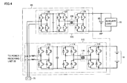
- Fig. 4 represents a circuit of bidirectional charger 60 shown in Fig. 1 .
- bidirectional charger 60 includes a main circuit 110 and a sub power supply circuit 120.
- Main circuit 110 includes AC/DC conversion units 112, 114, 118, and insulation transformer 116.
- Each of AC/DC conversion units 112, 114, 118 is constituted of a single-phase bridge circuit and can perform power conversion in a bidirectional manner.
- AC/DC conversion unit 112 converts alternate-current power from external power supply 90 inputted from power receiving unit 55 during external charging to direct-current power and outputs power to AC/DC conversion unit 114 based on signal CNTL1 from PM-ECU 80 ( Fig. 1 ).
- AC/DC conversion unit 112 can convert direct-current power received from AC/DC conversion unit 114 to alternate-current power and supply power to electrical outlet 75.
- AC/DC conversion unit 114 converts direct-current power received from AC/DC conversion unit 112 to high-frequency alternate-current power and outputs power to insulation transformer 116. Moreover, during a supply of power from main power storage device 10 to electrical outlet 75, AC/DC conversion unit 114 can convert alternate-current power received from insulation transformer 116 to direct-current power and output power to AC/DC conversion unit 112.
- Insulation transformer 116 includes a core made of magnetic material, and a primary coil and a secondary coil wound around the core.
- the primary coil and the secondary coil are electrically insulated and are connected respectively to AC/DC conversion units 114, 118.
- Insulation transformer 116 then performs voltage conversion between AC/DC conversion units 114,118 in accordance with a winding ratio of the primary coil and the secondary coil.
- AC/DC conversion unit 118 converts alternate-current power outputted from insulation transformer 116 to direct-current power and outputs power to main power storage device 10 ( Fig. 1 ). Moreover, during a supply of power from main power storage device 10 to electrical outlet 75, AC/DC conversion unit 118 can convert direct-current power outputted from main power storage device 10 to high-frequency alternate-current power and output power to insulation transformer 116.
- Electrical outlet 75 is then connected to AC/DC conversion unit 112 on a side of power receiving unit 55.
- the location of connection of electrical outlet 75 is not limited to this.
- Electrical outlet 75 may be connected to a primary side or a secondary side of insulation transformer 116.
- Electrical outlet 75 may also be connected to the direct-current line between AC/DC conversion unit 112 and AC/DC conversion unit 114 as long as the output of electrical outlet 75 is direct-current power.
- Sub power supply circuit 120 is connected to AC/DC conversion unit 112 of main circuit 110 on a side of power receiving unit 55.
- a circuit configuration of sub power supply circuit 120 is similar to that of main circuit 110.
- a capacity of sub power supply circuit 120 is smaller than that of main circuit 110. This is because sub power supply circuit 120 is provided to obtain auxiliary power during external charging from external power supply 90, and a capacity is sufficient even if it is smaller than that of main circuit 110.
- Sub power supply circuit 120 includes AC/DC conversion units 122, 124, 128 and an insulation transformer 126.
- Each of AC/DC conversion units 122, 124, 128 is constituted of a single-phase bridge circuit and can perform power conversion in a bidirectional manner.
- AC/DC conversion unit 122 converts alternate-current power from external power supply 90 inputted from power receiving unit 55 during eternal charging to direct-current power and outputs power to AC/DC conversion unit 124 based on signal CNTL1 from PM-ECU 80.
- AC/DC conversion unit 122 can convert direct-current power received from AC/DC conversion unit 124 to alternate-current power and supply power to electrical outlet 75.
- AC/DC conversion unit 124 converts direct-current power received from AC/DC conversion unit 122 to high-frequency alternate-current power and outputs power to insulation transformer 126. Moreover, during a supply of power from auxiliary power storage device 65 to electrical outlet 75, AC/DC conversion unit 124 can convert alternate-current power received from insulation transformer 126 to direct-current power and output power to AC/DC conversion unit 122.
- Insulation transformer 126 includes a core made of magnetic material, and a primary coil and a secondary coil wound around the core.
- the primary coil and the secondary coil are electrically insulated and are connected respectively to AC/DC conversion units 124, 128.
- Insulation transformer 126 then performs voltage conversion between AC/DC conversion units 124, 128 in accordance with a winding ratio of the primary coil and the secondary coil.
- AC/DC conversion unit 128 converts alternate-current power outputted from insulation transformer 126 to direct-current power and outputs power to auxiliary power storage device 65. Moreover, during a supply of power from auxiliary power storage device 65 to electrical outlet 75, AC/DC conversion unit 128 can convert direct-current power outputted from auxiliary power storage device 65 to high-frequency alternate-current power and output power to insulation transformer 126.
- a part of power from external power supply 90 inputted from power receiving unit 55 is further converted by AC/DC conversion unit 122 of sub power supply circuit 120 to direct-current power, and converted by AC/DC conversion unit 124 to high-frequency alternate-current power.
- High-frequency alternate-current power outputted from AC/DC conversion unit 124 is given via insulation transformer 126 to AC/DC conversion unit 128, converted by AC/DC conversion unit 128 to direct-current power, and supplied to auxiliary load 70 and auxiliary power storage device 65.
- power outputted from main power storage device 10 is converted by AC/DC conversion unit 118 of main circuit 110 to high-frequency alternate-current power.
- High-frequency alternate-current power outputted from AC/DC conversion unit 118 is given via insulation transformer 116 to AC/DC conversion unit 114, converted by AC/DC conversion unit 112 to alternate-current power, and supplied to electrical outlet 75.
- auxiliary power storage device 65 power outputted from auxiliary power storage device 65 is converted by AC/DC conversion unit 128 of sub power supply circuit 120 to high-frequency alternate-current power.
- High-frequency alternate-current power outputted from AC/DC conversion unit 128 is given via insulation transformer 126 to AC/DC conversion unit 124, converted by AC/DC conversion unit 122 to alternate-current power, and supplied to electrical outlet 75.
- Fig. 5 represents a flowchart for determination of a power supply path to electrical outlet 75. It should be noted that the processes shown in this flowchart are invoked from a main routine at every constant time or at each time when a certain condition is met, and then the processes are executed. Referring to Fig. 5 , PM-ECU 80 determines whether or not an AC switch for allowing a user to request use of electrical outlet 75 is turned on (step S10). When it is determined that the AC switch is turned off (NO in step S10), PM-ECU 80 shifts the process to step S80 without executing subsequent series of processes.
- step S10 when it is determined that the AC switch is turned on (YES in step S10), PM-ECU 80 determines whether or not the SOC of main power storage device 10 is higher than a predetermined threshold value indicating lowering of the SOC (step S20). When it is determined that the SOC is higher than the threshold value (YES in step S20), PM-ECU 80 determines whether or not a state of the vehicle is in a READY-ON state (step S30). The READY-ON state indicates that a vehicle system is started.
- PM-ECU 80 determines whether or not a sum of EV requested power Pev received from MG-ECU 48 ( Fig. 1 ) and an output power Pout indicating power outputted from electrical outlet 75 is smaller than or equal to outputtable power Wout of main power storage device 10 (step S40).
- Output power Pout is detected by a power sensor, a voltage sensor, and a current sensor, which are not illustrated in the drawings.
- Rated power of electrical outlet 75 indicating maximum used power of electrical outlet 75 may be used in place of output power Pout of a measured value.
- PM-ECU 80 controls inverter 24 and converter 20 so that motor generator 34 generates EV requested power Pev, and controls bidirectional charger 60 so that power is supplied from main power storage device 10 to electrical outlet 75 (step S50). Accordingly, traveling power is supplied via path "c" shown in Fig. 3 from main power storage device 10 to motor generator 34, and power is supplied via path "d" from main power storage device 10 to electrical outlet 75.
- step S40 when it is determined that a sum of EV requested power Pev and output power Pout of electrical outlet 75 is larger than outputtable power Wout of main power storage device 10 (NO in step S40), PM-ECU 80 controls inverter 24 and converter 20 so that motor generator 34 generates EV requested power Pev, and controls bidirectional charger 60 so that power is supplied from auxiliary power storage device 65 to electrical outlet 75 (step S60). Accordingly, traveling power is supplied via path "c" shown in Fig. 3 from main power storage device 10 to motor generator 34, and power is supplied via path "e” from auxiliary power storage device 65 to electrical outlet 75.
- PM-ECU 80 disables use of electrical outlet 75 (step S70).
- the disabling of electrical outlet 75 is achieved by, for example, shutting down bidirectional charger 60, turning off a non-illustrated relay provided between bidirectional charger 60 and electrical outlet 75, or the like.
- auxiliary power storage device 65 when travel driving force (EV requested power Pev) increases during the use of electrical outlet 75, power stored in auxiliary power storage device 65 is outputted via sub power supply circuit 120 of bidirectional charger 60 to electrical outlet 75. Accordingly, it is not necessary to distribute power outputted from main power storage device 10 during the use of electrical outlet 75 to electrical outlet 75.
- power can be supplied to an electrical appliance including a home appliance while securing traveling performance.
- the charger for external charging is set to be bidirectional so that power can be outputted from main power storage device 10 and auxiliary power storage device 65 to electrical outlet 75. Therefore, it is not necessary to separately provide a dedicated converter for outputting power to electrical outlet 75.
- sub power supply circuit 120 having a small capacity is set to be bidirectional so that power can be outputted from auxiliary power storage device 65 to electrical outlet 75. Therefore, a loss can be reduced when power is outputted from auxiliary power storage device 65 to electrical outlet 75.
- auxiliary power storage device 65 when an increase in traveling power is expected based on information of a traveling path, the SOC of auxiliary power storage device 65 is raised in advance to prepare for a supply of power from auxiliary power storage device 65 to electrical outlet 75.
- Fig. 6 represents an overall configuration of a hybrid vehicle shown as one example of an electrically-driven vehicle according to the second embodiment.
- this hybrid vehicle 100A further includes a car navigation device 85 and also includes a PM-ECU 80A in place of PM-ECU 80 in the configuration of hybrid vehicle 100 according to the first embodiment shown in Fig. 1 .
- Car navigation device 85 collects information related to a traveling path to a destination and transmits the information to PM-ECU 80A.
- the traveling path information includes, for example, a distance to a destination, a gradient of a traveling path, a speed limit, and the like.
- PM-ECU 80A estimates EV traveling power along a traveling path to a destination based on traveling path information received from car navigation device 85. For example, EV traveling power is estimated along a traveling path at each predetermined unit interval, and an increase in EV traveling power is estimated in a traveling section such as a slope, a highway, or the like. PM-ECU 80A executes a control of raising the SOC of auxiliary power storage device 65 before hybrid vehicle 100A travels in the traveling section for which an increase in the EV traveling power is estimated. Specifically, PM-ECU 80A controls DC/DC converter 50 so that power is supplied from main power storage device 10 via DC/DC converter 50 to auxiliary power storage device 65.
- PM-ECU 80A Other functions of PM-ECU 80A are the same as those of PM-ECU 80 of the first embodiment. Further, other configuration of hybrid vehicle 100A is also the same as that of hybrid vehicle 100 of the first embodiment.
- Fig. 7 represents a flowchart for describing the control executed by PM-ECU 80A shown in Fig. 6 .
- the processes shown in this flowchart are also invoked from a main routine at every constant time or at each time when a certain condition is met, and then the processes are executed.
- PM-ECU 80A determines whether or not an AC switch for allowing a user to request use of electrical outlet 75 is turned on (step S110). When it is determined that the AC switch is turned off (NO in step S110), PM-ECU 80A shifts the process to step S210 without executing subsequent series of processes.
- step S110 when it is determined that the AC switch is turned on (YES in step S110), PM-ECU 80A determines whether or not a destination is set in car navigation device 85 (step S120). When the destination is not set (NO in step S120), PM-ECU 80A shifts the process to step S210.
- step S120 when it is determined that a destination is set (YES in step S120), PM-ECU 80A obtains traveling path information to the destination (information such as a gradient of the traveling path, a speed limit, or the like) from car navigation device 85 (step S130). PM-ECU 80A then uses the obtained traveling path information to calculate EV requested power Pev along the traveling path to the destination, so that EV traveling power along the traveling path to the destination is estimated (step S140).
- traveling path information to the destination information such as a gradient of the traveling path, a speed limit, or the like
- PM-ECU 80A extracts a traveling section in which a value obtained by adding output power Pout of electrical outlet 75 to EV requested power Pev calculated in step S140 is larger than outputtable power Wout of main power storage device 10 (step S150).
- Output power Pout (W) of electrical outlet 75 is the rated power of electrical outlet 75 to prepare for the maximum use of electrical outlet 75.
- PM-ECU 80A estimates an output power amount (Wh) of electrical outlet 75 in each traveling section extracted in step S150 (step S160). For example, a traveling time in each of extracted traveling section can be estimated based on traveling path information to the destination obtained from car navigation device 85, so that the output power amount (Wh) of electrical outlet 75 in each traveling section can be calculated based on the estimated traveling time.
- PM-ECU 80A calculates the SOC of auxiliary power storage device 65 (step S170).
- the SOC of auxiliary power storage device 65 can be calculated by using various known methods based on a voltage, an input/output current, and the like of auxiliary power storage device 65.
- PM-ECU 80A determines whether or not it is necessary to charge auxiliary power storage device 65 in advance for the next traveling section from a current traveling point among traveling sections extracted in step S150 (step S180). Specifically, determination is made on whether or not it is necessary to charge auxiliary power storage device for the next traveling section extracted in step S150 based on the electrical outlet output power amount of the next traveling section calculated in step S160 and the SOC of auxiliary power storage device 65 calculated in step S170.
- PM-ECU 80A controls operation of DC/DC converter 50 so that power is supplied from main power storage device 10 via DC/DC converter 50 to auxiliary power storage device 65 (step S190).
- PM-ECU 80A shifts the process to step S200.
- PM-ECU 80A determines whether or not hybrid vehicle 100A has arrived at the destination based on the traveling path information from car navigation device 85 (step S200). When it is determined that hybrid vehicle 100A has not yet arrived at the destination (NO in step S200), PM-ECU 80A returns the process to step S170. When it is determined that hybrid vehicle 100A has arrived at the destination (YES in step S200), PM-ECU 80A shifts the process to step S210.
- the SOC of auxiliary power storage device 65 is raised in advance to prepare for a supply of power from auxiliary power storage device 65 to electrical outlet 75 when an increase in the traveling power is expected.
- disabling of electrical outlet 75 due to a shortage of power of auxiliary power storage device 65 can be avoided.
- auxiliary power storage device 65 when an increase in traveling power is expected based on a traveling path, the SOC of auxiliary power storage device 65 is raised in advance to prepare for a supply of power from auxiliary power storage device 65 to electrical outlet 75.
- auxiliary power storage device 65 when power is supplied from main power storage device 10 to auxiliary power storage device 65 to raise the SOC of auxiliary power storage device 65, power can be supplied via the sub power supply circuit of the bidirectional charger from main power storage device 10 to auxiliary power storage device 65.
- the sub power supply circuit of the bidirectional charger is provided to supply power from external power supply 90 to auxiliary load 70 during the external charging, and the loss is small even though a capacity is small. Therefore, in this third embodiment, a power supply path is switched from main power storage device 10 to auxiliary power storage device 65 in accordance with the amount of power supplied from main power storage device 10 to auxiliary power storage device 65.
- Fig. 8 represents an overall configuration of a hybrid vehicle which is shown as one example of an electrically-driven vehicle according to the third embodiment.
- this hybrid vehicle 100B includes a bidirectional charger 60A and a PM-ECU 80B in place of bidirectional charger 60 and PM-ECU 80A respectively in the configuration of hybrid vehicle 100A in the second embodiment shown in Fig. 6 .
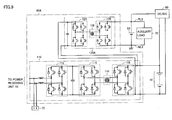
- Fig. 9 represents a circuit of bidirectional charger 60A shown in Fig. 8 .
- bidirectional charger 60A includes a sub power supply circuit 120A in place of sub power supply circuit 120 in the configuration of bidirectional charger 60 shown in Fig. 4 .
- Sub power supply circuit 120A has a configuration in which AC/DC conversion unit 122 is not included in sub power supply circuit 120 shown in Fig. 4 .
- the direct-current side of AC/DC conversion unit 124 is connected to the direct-current side of main circuit 110 (on the side of main power storage device 10).
- This bidirectional charger 60A can supply power from main power storage device 10 via sub power supply circuit 120A to auxiliary power storage device 65.
- power outputted from main power storage device 10 is supplied to AC/DC conversion unit 124 of sub power supply circuit 120A and converted by AC/DC conversion unit 124 to high-frequency alternate-current power.
- the high-frequency alternate-current power outputted from AC/DC conversion unit 124 is given via insulation transformer 126 to AC/DC conversion unit 128, converted by AC/DC conversion unit 128 to direct-current power, and supplied to auxiliary power storage device 65.
- main power storage device 10 During charging of main power storage device 10 by external power supply 90 ( Fig. 8 ), power is supplied from power receiving unit 55 via main circuit 110 to main power storage device 10, and an output of main circuit 110 is further subjected to voltage conversion by sub power supply circuit 120A and supplied to auxiliary load 70 and auxiliary power storage device 65.
- power can be supplied from main power storage device 10 via bidirectional charger 60A to auxiliary power storage device 65 as described above.
- auxiliary power storage device 65 there are two paths for supplying power from main power storage device 10 to auxiliary power storage device 65 to raise the SOC of auxiliary power storage device 65 in advance when an increase in traveling power is expected.
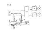
- Fig. 10 represents a power supply path from main power storage device 10 to auxiliary power storage device 65.
- paths for supplying power from main power storage device 10 to auxiliary power storage device 65 there are two paths including a path "f" passing through DC/DC converter 50 and a path “g” passing through bidirectional charger 60A (more specifically, sub power supply circuit 120A).
- DC/DC converter 50 is provided originally to generate power for auxiliary load 70, and it has enough capacity to supply power to auxiliary load 70.
- bidirectional charger 60A is provided for external charging, it is configured to be bidirectional so as to enable a supply of power from main power storage device 10 and auxiliary power storage device 65 to electrical outlet 75 and a supply of power from main power storage device 10 to auxiliary power storage device 65. As shown in Fig. 9 , a supply of power from main power storage device 10 to auxiliary power storage device 65 is performed via sub power supply circuit 120A of bidirectional charger 60A.
- Sub power supply circuit 120A is provided to secure limited power of auxiliary load 70 operated during the external charging from external power supply 90, and it has a smaller capacity and a smaller loss as compared to DC/DC converter 50. Therefore, in this third embodiment, when power supplied from main power storage device 10 to auxiliary power storage device 65 to raise the SOC of auxiliary power storage device 65 in advance is within the rating of sub power supply circuit 120A of bidirectional charger 60A, power is supplied via sub power supply circuit 120A of bidirectional charger 60A from main power storage device 10 to auxiliary power storage device 65.
- Fig. 11 represents a flowchart for describing the control executed by PM-ECU 80B shown in Fig. 8 .
- this flowchart further includes steps S182, S 184 in the flowchart shown in Fig. 7 .
- step S180 when it is determined that it is necessary to charge auxiliary power storage device 65 in advance for the next traveling section from a current traveling point among traveling sections extracted in step S150 (YES in step S180), PM-ECU 80B determines whether or not charging power is within the rating of sub power supply circuit 120A (step S182). For example, when the SOC of auxiliary power storage device 65 is lowered significantly, and charging with power exceeding the rating of sub power supply circuit 120A is requested, it is determined that charging power exceeds the rating of sub power supply circuit 120A.
- step S182 when it is determined that charging power from main power storage device 10 to auxiliary power storage device 65 is within the rating of sub power supply circuit 120A (YES in step S182), PM-ECU 80B controls operation of sub power supply circuit 120A so that power is supplied from main power storage device 10 via sub power supply circuit 120A of bidirectional charger 60A to auxiliary power storage device 65 (step S184).
- step S182 when it is determined that charging power from main power storage device 10 to auxiliary power storage device 65 exceeds the rating of sub power supply circuit 120A (NO in step S182), the process is shifted to step S190, and DC/DC converter 50 is controlled so that power is supplied from main power storage device 10 via DC/DC converter 50 to auxiliary power storage device 65.
- auxiliary power storage device 65 in the case where the SOC of auxiliary power storage device 65 is raised in advance to prepare for a supply of power from auxiliary power storage device 65 to electrical outlet 75, when the amount of power supplied to auxiliary power storage device 65 is not large, power is supplied from main power storage device 10 to auxiliary power storage device 65 via sub power supply circuit 120A having a smaller capacity than DC/DC converter 50.
- the loss can be suppressed more than the case where a supply of power is uniformly performed via DC/DC converter 50 from main power storage device 10 to auxiliary power storage device 65.
- Fig. 12 represents an overall configuration of a hybrid vehicle shown as one example of an electrically-driven vehicle according to the fourth embodiment.
- this hybrid vehicle 100C includes power converter 150 and PM-ECU 80C in place of bidirectional charger 60 and PM-ECU 80 respectively in the configuration of hybrid vehicle 100 shown in Fig. 1 .
- Fig. 13 represents a configuration of power converter 150 shown in Fig. 12 .
- power converter 150 includes a voltage-lowering circuit 152, a voltage-raising circuit 154, and an inverter 156.
- Voltage-lowering circuit 152 is electrically connected to positive line PL1 and negative line NL1 to which main power storage device 10 is connected.
- Inverter 156 is connected between voltage-lowering circuit 152 and electrical outlet 75.
- Voltage-raising circuit 154 is connected between power lines and auxiliary power storage device 65, where the power lines are provided between voltage-lowering circuit 152 and inverter 156.
- Voltage-lowering circuit 152 lowers the voltage of power outputted from main power storage device 10 and output the power to inverter 156.
- Voltage-raising circuit 154 raises the voltage of power outputted from auxiliary power storage device 65 and supplies the power to inverter 156.
- Inverter 156 converts direct-current power received from voltage-lowering circuit 152 or voltage-raising circuit 154 to predetermined alternate-current power and supply the power to electrical outlet 75.
- PM-ECU 80C executes a control of supplying power from bidirectional charger 60 to electrical outlet 75. Specifically, when EV requested power Pev received from MG-ECU 48 increases during the use of electrical outlet 75, PM-ECU 80C generates signal CNTL3 so as to subject power stored in auxiliary power storage device 65 to voltage conversion and supply the power to electrical outlet 17, and outputs the signal to power converter 150. For example, on the other hand, when EV requested power Pev is not large, PM-ECU 80C generates signal CNTL3 so as to supply power stored in main power storage device 10 to electrical outlet 75 and outputs the signal to power converter 150.
- hybrid vehicle 100C Other configurations of hybrid vehicle 100C are the same as those of hybrid vehicle 100 shown in Fig. 1 .
- auxiliary power storage device 65 can be charged from main power storage device 10 via voltage-lowering circuit 152 and voltage-raising circuit 154. Accordingly, the functions similar to those of second and third embodiments can be achieved except for the external charging function.
- electrical outlet 75 is connected to AC/DC conversion unit 112 of main circuit 110 on a side of power receiving unit 55.
- connection part of electrical outlet 75 is not limited to that location.
- Electrical outlet 75 may be connected to insulation transformer 116 on the primary side or the secondary side.
- hybrid vehicle 100 (100A to 100C) is described.
- this invention is not limited to the control during EV traveling of the hybrid vehicle, and it can be applied also to the HV traveling. Further, the scope of application of this invention is not limited to a hybrid vehicle but also includes electrically-driven vehicles such as an electric vehicle and a fuel cell vehicle having no engine mounted.
- hybrid vehicle 100 shown as one example of an electrically-driven vehicle is described as a series/parallel type hybrid vehicle capable of splitting motive power of engine 36 by planetary gear 38 and transmitting the motive power to drive wheels 44 and motor generator 32.
- this invention can be applied also to hybrid vehicles of other types.
- this invention can be applied also to, for example, a so-called series-type hybrid vehicle which uses engine 36 only for driving motor generator 32 and generates drive force of a vehicle only with motor generator 34, and a motor-assist type hybrid vehicle with an engine as a main motive power and a motor providing an assist as needed.
- motor generator 34 corresponds to one example of "electric motor” in the present invention
- each of bidirectional chargers 60, 60A and power converter 150 corresponds to one example of “power conversion device” in this invention.
- PM-ECU 80, 80A to 80C corresponds to one example of "control device” in this invention
- car navigation device 85 corresponds to one example of "information device” in this invention.
Landscapes
- Engineering & Computer Science (AREA)
- Power Engineering (AREA)
- Transportation (AREA)
- Mechanical Engineering (AREA)
- Life Sciences & Earth Sciences (AREA)
- Sustainable Development (AREA)
- Sustainable Energy (AREA)
- Electric Propulsion And Braking For Vehicles (AREA)
- Charge And Discharge Circuits For Batteries Or The Like (AREA)
- Dc-Dc Converters (AREA)
Abstract
Description
- The present invention relates to an electrically-driven vehicle and a method for controlling the same, and more particularly to an electrically-driven vehicle provided with a power output unit which outputs power to an electrical appliance including a home appliance, and a method for controlling the same.
- In electrically-driven vehicles such as an electric vehicle having a motor as a motive power source which receives a supply of power from a power storage device such as a battery and generates a travel driving force, and a hybrid vehicle further having an engine as a motive power source, there has been proposed a configuration which is able to subject power stored in a power storage device to voltage conversion and output power to an electrical appliance such as a home appliance.
- Japanese Patent Laying-Open No.
2002-374604 -
- PTD 1 : Japanese Patent Laying-Open No.
2002-374604 - PTD 2 : Japanese Patent Laying-Open No.
2008-312395 - PTD 3 : Japanese Patent Laying-Open No.
2004-236472 - In the vehicle disclosed in Japanese Patent Laying-Open No.
2002-374604 - This invention was made to solve the problem described above, and its object is to provide an electrically-driven vehicle which is able to supply power to an electrical appliance including a home appliance while maintaining the traveling performance.
- Moreover, another object of this invention is to provide a method for controlling an electrically-driven vehicle which is able to supply power to an electrical appliance including a home appliance while maintaining the traveling performance.
- According to the present invention, an electrically-driven vehicle includes a main power storage device, an electric motor, an auxiliary power storage device, a power output unit, a power conversion device, and a control device. The electric motor receives a supply of power from the main power storage device and generates a travel driving force. The power output unit is configured to be able to output power to an electrical appliance including a home appliance. The power conversion device is electrically connected to the main power storage device, the auxiliary power storage device and the power output unit, and is configured to be able to subject power stored in the main power storage device or power stored in the auxiliary power storage device to voltage conversion and output power to the power output unit. The control device controls the power conversion device to subject power stored in the auxiliary power storage device to voltage conversion and output power to the power output unit when the travel driving force increases during use of the power output unit.
- Preferably, during use of the power output unit, when the travel driving force increases to cause an output of the main power storage device to exceed outputtable power indicating power which can be outputted by the main power storage, the control device controls the power conversion device to subject power stored in the auxiliary power storage device to voltage conversion and output power to the power output unit.
- Preferably, the power conversion device includes a charger which subjects power supplied from a power supply provided outside of the vehicle to voltage conversion and charges the main power storage device and the auxiliary power storage device. The charger is configured to be able to subject power conversion in a bidirectional manner so as to be able to subject power stored in the main power storage device or power stored in the auxiliary power storage device to voltage conversion and output power to the power output unit.
- More preferably, the charger includes a main circuit and a sub power supply circuit. The main circuit is configured to be able to subject voltage conversion in a bidirectional manner between the power supply provided outside of the vehicle and the main power storage device. The sub power supply circuit is configured to be able to subject voltage conversion in a bidirectional manner between the power supply provided outside of the vehicle and the auxiliary power storage device and has a smaller capacity than the main circuit.
- Preferably, when the travel driving force increases, the control device further controls a state of charge of the auxiliary power storage device so as to raise a state of charge of the auxiliary power storage device in advance.
- More preferably, the electrically-driven vehicle further includes an information device having information related to a traveling path. When an increase in the travel driving force is estimated based on traveling path information from the information device, the control device controls a state of charge of the auxiliary power storage device so as to raise a state of charge of the auxiliary power storage device in advance.
- Preferably, the electrically-driven vehicle further includes a voltage converter. The voltage converter sujects power outputted from the main power storage device to voltage conversion and outputs power to the auxiliary power storage device. The power conversion device includes a charger which subjects power supplied from a power supply provided outside of the vehicle to voltage conversion and charges the main power storage device and the auxiliary power storage device. The charger includes a main circuit and a sub power supply circuit. The main circuit is configured to be able to subject voltage conversion in a bidirectional manner between the power supply provided outside of the vehicle and the main power storage device. The sub power supply circuit is configured to be able to subject voltage conversion in a bidirectional manner between the power supply provided outside of the vehicle and the auxiliary power storage device and has a smaller capacity than the main circuit. The sub power supply circuit is electrically connected to the main circuit on a side of the main power storage device. In a case where the control device controls a state of charge of the auxiliary power storage device so as to raise a state of charge of the auxiliary power storage device in advance, when power supplied to the auxiliary power storage device is within rating of the sub power supply circuit, the control device controls the sub power supply circuit such that power is supplied from the main power storage device to the auxiliary power storage device by the sub power supply circuit, and when power supplied to the auxiliary power storage device exceeds rating of the sub power supply circuit, the control device controls the voltage converter such that power is supplied from the main power storage device to the auxiliary power storage device by the voltage converter.
- Moreover, according to this invention, a control method is a method for controlling an electrically-driven vehicle. The electrically-driven vehicle includes a main power storage device, an electric motor, an auxiliary power storage device, a power output unit, and a power conversion device. The electric motor receives a supply of power from the main power storage device and generates a travel driving force. The power output unit is configured to be able to output power to an electrical appliance including a home appliance. The power conversion device is electrically connected to the main power storage device, the auxiliary power storage device and the power output unit, and is configured to be able to subject power stored in the main power storage device or power stored in the auxiliary power storage device to voltage conversion and output power to the power output unit. The controlling method includes the steps of determining whether or not a use of the power output unit is requested, and controlling the power conversion device to subject power stored in the auxiliary power storage device to voltage conversion and output power to the power output unit when the travel driving force increases in a case where a use of the power output unit is requested.
- Preferably, the step of controlling the power conversion device includes the steps of determining whether or not an increase in the travel driving force causes an output of the main power storage device to exceed outputtable power indicating power which can be outputted by the main power storage device during use of the power output unit, and controlling the power conversion device to subject power stored in the auxiliary power storage device to voltage conversion and output power to the power output unit when it is determined that an output of the main power storage device exceeds the outputtable power.
- Preferably, the controlling method further includes the step of controlling a state of charge of the auxiliary power storage device so as to raise a state of charge of the auxiliary power storage device in advance when the travel driving force increases.
- More preferably, the electrically-driven vehicle further includes a voltage converter. The voltage converter subjects power outputted from the main power storage device to voltage conversion and outputs power to the auxiliary power storage device. The power conversion device includes a charger which subjects power supplied from a power supply provided outside of the vehicle to voltage conversion and charges the main power storage device and the auxiliary power storage device. The charger includes a main circuit and a sub power supply circuit. The main circuit is configured to be able to subject voltage conversion in a bidirectional manner between the power supply provided outside of the vehicle and the main power storage device. The sub power supply circuit is configured to be able to subject voltage conversion in a bidirectional manner between the power supply provided outside of the vehicle and the auxiliary power storage device and has a smaller capacity than the main circuit. The sub power supply circuit is electrically connected to the main circuit on a side of the main power storage device. The step of controlling a state of charge of the auxiliary power storage device includes the steps of determining whether or not power supplied to the auxiliary power storage device is within rating of the sub power supply circuit, controlling the sub power supply circuit such that power is supplied from the main power storage device to the auxiliary power storage device by the sub power supply circuit when it is determined that the power is within rating of the sub power supply circuit in the step of determining, and controlling the voltage converter such that power is supplied from the main power supply circuit to the auxiliary power storage device by the voltage converter when it is determined that power exceeds the rating of the sub power supply circuit in the step of determining.
- According to the present invention, when a travel driving force increases during use of the power output unit, the power conversion device is controlled so as to subject power stored in the auxiliary power storage device to voltage conversion and output power to the power output unit. Accordingly, it would not be necessary to allow power outputted from the main power storage device during use of the power output unit to be distributed to the power output unit. Thus, according to the present invention, power can be supplied to an electrical appliance including a home appliance while securing traveling performance.
-
-
Fig. 1 represents an overall configuration of a hybrid vehicle shown as one example of an electrically-driven vehicle according to a first embodiment of the present invention. -
Fig. 2 represents a flow of power during external charging. -
Fig. 3 represents a flow of power during use of an electrical outlet. -
Fig. 4 represents a circuit of the bidirectional charger shown inFig. 1 . -
Fig. 5 represents a flowchart for determining a power supply path to the electrical outlet. -
Fig. 6 represents an overall configuration of a hybrid vehicle shown as one example of an electrically-driven vehicle according to the second embodiment. -
Fig. 7 represents a flowchart for description of the control executed by the PM-ECU shown inFig. 6 . -
Fig. 8 represents an overall configuration of a hybrid vehicle shown as one example of an electrically-driven vehicle according to the third embodiment. -
Fig. 9 represents a circuit of the bidirectional charger shown inFig. 8 . -
Fig. 10 represents a power supply path from the main power storage device to the auxiliary power storage device. -
Fig. 11 represents a flowchart for description of the control executed by the PM-ECU shown inFig. 8 . -
Fig. 12 represents an overall configuration of a hybrid vehicle shown as one example of an electrically-driven vehicle according to the fourth embodiment. -
Fig. 13 represents a configuration of the power converter shown inFig. 12 . - Hereinafter, embodiments of the present invention will be described with reference to the drawings. In the drawings, the same or corresponding parts have the same reference numerals allotted, and description thereof will not be repeated.
-
Fig. 1 represents an overall configuration of a hybrid vehicle shown as one example of an electrically-driven vehicle according to the first embodiment of the present invention. Referring toFig. 1 , ahybrid vehicle 100 includes a mainpower storage device 10, a system main relay (hereinafter, also referred to as "SMR (System Main Relay)") 15, aconverter 20,inverters motor generators hybrid vehicle 100 further includes anengine 36,planetary gears transmission gear 42,drive wheels 44, a DC/DC converter 50, positive lines PL1, PL2, and negative lines NL1, NL2. - Main
power storage device 10 is a rechargeable direct-current power supply, and is constituted of, for example, a secondary battery of nickel metal hydride, lithium ion, or the like. Mainpower storage device 10 stores power supplied from a power supply provided outside of the vehicle (hereinafter, referred to as "external power supply") 90 as well as power generated bymotor generators power storage device 10. - Main
power storage device 10 supplies stored power toconverter 20. Moreover, mainpower storage device 10 can supply power via DC/DC converter 50 to a positive line PL3 and a negative line NL3 to which an auxiliarypower storage device 65 and anauxiliary load 70 are connected. Further, mainpower storage device 10 can supply power also to anelectrical outlet 75 via abidirectional charger 60. -
SMR 15 is provided between a positive line PL1, a negative line NL1 connected to mainpower storage device 10 and a positive line PL2, a negative line NL2 connected toconverter 20.SMR 15 is a relay for performing electrical connection/disconnection between positive line PL1, negative line NL1 and positive line PL2, negative line NL2. -
Converter 20 is provided between positive line PL2, negative line NL2 andinverters Converter 20 raises an input voltage ofinverters 22, 24 (a voltage betweenconverter 20 andinverters 22, 24) to be higher than or equal to a voltage of mainpower storage device 10 based on a signal PWC from an MG-ECU 48.Converter 20 is constituted of, for example, a current reversible chopper circuit. -
Inverters converter 20 in parallel with each other.Inverter 22 drivesmotor generator 32 based on a signal PWI1 from MG-ECU 48.Inverter 24 drivesmotor generator 34 based on a signal PWI2 from MG-ECU 48. Each ofinverters - Each of
motor generators Motor generator 32 is mechanically connected toplanetary gear 38.Motor generator 32 generates starting torque ofengine 36 mechanically coupled viaplanetary gear 38 and startsengine 36. Afterengine 36 is started,motor generator 32 is driven byengine 36 and generates power. -
Motor generator 34 is mechanically connected toplanetary gear 40.Motor generator 34 then generates driving torque for traveling and drives drivewheels 44 viaplanetary gear 40 andtransmission gear 42. At the time of braking of the vehicle,motor generator 34 receives kinetic energy of the vehicle fromdrive wheels 44 and generates power.Planetary gear 40 shifts an output ofmotor generator 34 and transmits the output totransmission gear 42. It should be noted thatplanetary gear 40 may be omitted, andmotor generator 34 may be directly connected totransmission gear 42. -
Engine 36 converts thermal energy generated by combustion of fuel to kinetic energy for motion elements such as a piston, a rotor, or the like, and outputs the converted kinetic energy to at least one ofdrive wheels 44 andmotor generator 32 viaplanetary gear 38. In other words,planetary gear 38 is mechanically connected tomotor generator 32,engine 36, andtransmission gear 42, and the output ofengine 36 is distributed tomotor generator 32 andtransmission gear 42 and outputted. - DC/
DC converter 50 is connected between positive line PL2, negative line NL2 and positive line PL3, negative line NL3. DC/DC converter 50 converts power supplied from positive line PL2, negative line NL2 to a voltage level ofauxiliary load 70 and outputs power to positive line PL3 based on a signal CNTL2 from PM-ECU 80. - Moreover,
hybrid vehicle 100 further includes apower receiving unit 55,bidirectional charger 60, auxiliarypower storage device 65,auxiliary load 70,electrical outlet 75, positive line PL3, and negative line NL3. Further,hybrid vehicle 100 includes a battery ECU (Electronic Control Unit) 46, MG-ECU 48, and PM-ECU 80. -
Power receiving unit 55 is configured to be connectable toexternal power supply 90 and outputs power supplied fromexternal power supply 90 tobidirectional charger 60. Moreover,power receiving unit 55 outputs a connection signal CNCT indicating a connection state withexternal power supply 90 to PM-ECU 80. Whenexternal power supply 90 is connected to power receivingunit 55,power receiving unit 55 activates connection signal CNCT.Power receiving unit 55 may be constituted of an inlet which can be engaged with a connector on a side ofexternal power supply 90, or a plug which can be engaged with an outlet ofexternal power supply 90. -
Bidirectional charger 60 is electrically connected to power receivingunit 55, positive line PL1 and negative line NL1 to which mainpower storage device 10 is connected, positive line PL3 and negative line NL3 to which auxiliarypower storage device 65 andauxiliary load 70 are connected, andelectrical outlet 75.Bidirectional charger 60 converts power supplied fromexternal power supply 90 to a voltage level of mainpower storage device 10 and outputs power to positive line PL1 and negative line NL1 based on a signal CNTL1 from PM-ECU 80, and charges mainpower storage device 10. Further,bidirectional charger 60 converts power supplied fromexternal power supply 90 to a voltage level ofauxiliary load 70 and outputs power to positive line PL3 and negative line NL3, and supplies power toauxiliary load 70. - Further,
bidirectional charger 60 is configured to be able to subject power outputted from mainpower storage device 10 to voltage conversion and output power toelectrical outlet 75. Moreover,bidirectional charger 60 is further configured to be able to subject power outputted from auxiliarypower storage device 65 to voltage conversion and output power toelectrical outlet 75. In other words,bidirectional charger 60 can subject power supplied fromexternal power supply 90 to voltage conversion, and charge mainpower storage device 10 and supply power toauxiliary load 70, and can subject power stored in mainpower storage device 10 and auxiliarypower storage device 65 to voltage conversion and output power toelectrical outlet 75. As one example,bidirectional charger 60 subjects power stored in mainpower storage device 10 and auxiliarypower storage device 65 to voltage conversion to AC 100V and outputs power toelectrical outlet 75. Detailed configuration ofbidirectional charger 60 will be described later. - Auxiliary
power storage device 65 is a rechargeable direct-current power supply and is constituted of, for example, a secondary battery of lead, nickel-metal hydride, lithium ion, or the like. A capacitor may be used in place of the secondary battery. Auxiliarypower storage device 65 is connected to positive line PL3 and negative line NL3 and receives power frombidirectional charger 60 or DC/DC converter 50 to be charged.Auxiliary load 70 generally represents an auxiliary ofhybrid vehicle 100 which receives power from DC/DC converter 50,bidirectional charger 60, or auxiliarypower storage device 65 charged by those and operates. -
Electrical outlet 75 is a power output unit which outputs power to an electrical appliance such as a home appliance, a personal computer, or the like.Electrical outlet 75 is electrically connected tobidirectional charger 60 and outputs power received frombidirectional charger 60 to an electrical appliance connected toelectrical outlet 75. Moreover, forelectrical outlet 75, an AC switch (not illustrated) for rendering it to be usable is provided. When the AC switch is turned on, a signal ACSW outputted to PM-ECU 80 is activated. -
Battery ECU 46 sets outputtable power Wout indicating power which can be outputted by mainpower storage device 10. Outputtable power W is set through a software processing of executing pre-stored program at a CPU (Central Processing Unit) and/or a hardware processing by means of a dedicated electronic circuit. Outputtable power Wout is set to suppress over-discharging of mainpower storage device 10. Moreover,battery ECU 46 calculates a state of charge of main power storage device 10 (hereinafter, referred to as "SOC (State Of Charge)," and is expressed for example by a percentage with respect to a capacity of main power storage device 10). As a method for calculating the SOC, various known methods can be used, such as a calculation method of using a relationship between an open circuit voltage (OCV (Open Circuit Voltage)) and an SOC of mainpower storage device 10, a calculation method of using an integrated value of an input/output current, and the like.Battery ECU 46 then outputs outputtable power Wout and the SOC of mainpower storage device 10 to MG-ECU 48 and PM-ECU 80. - MG-
ECU 48 controls operation ofconverter 20 andinverters ECU 48 calculates a requested value of traveling power (hereinafter, referred to as "requested traveling power") from an operation amount on an accelerator pedal, a vehicle speed, and the like. MG-ECU 48 then generates a signal for driving motor generator 34 (for example, PWM (Pulse Width Modulation) signal) based on the calculated requested traveling power, and outputs the generated signal as signal PWI2 toinverter 24. - When the requested traveling power exceeds outputtable power Wout of main
power storage device 10, MG-ECU48 generates a signal for driving motor generator 32 (for example, PWM signal) and outputs the generated signal as signal PWI1 toinverter 22. Accordingly,engine 36 is started. Further, when the SOC is lowered to a predetermined threshold value indicating lowering of the SOC of mainpower storage device 10, MG-ECU 48 also generates signal PWI1 and outputs the signal to inverter 22 to startengine 36. Accordingly,motor generator 32 generates power with use of an output ofengine 36, so that mainpower storage device 10 is charged. - In the following, traveling with use of
only motor generator 34 prior to starting ofengine 36 will be referred to as EV (Electric Vehicle) traveling, and traveling with operation ofengine 36 will be referred to as HV (Hybrid Vehicle) traveling. MG-ECU 48 then outputs requested traveling power during EV traveling as EV requested power Pev to PM-ECU 80. Moreover, MG-ECU 48 generates a signal for driving converter 20 (for example, PWM signal) and outputs the generated signal as signal PWC toconverter 20. - PM-
ECU 80 controls operation ofbidirectional charger 60 through a software processing of executing pre-stored program at a CPU and/or a hardware processing by means of a dedicated electronic circuit. Specifically, during charging of mainpower storage device 10 by external power supply 90 (hereinafter referred to as "external charging"), PM-ECU 80 generates signal CNTL1 for drivingbidirectional charger 60 so as to supply power received frompower receiving unit 55 to mainpower storage device 10 andauxiliary load 70 and outputs the signal tobidirectional charger 60. - Moreover, PM-
ECU 80 determines use/non-use ofelectrical outlet 75 based on signal ACSW fromelectrical outlet 75 and executes a control of supplying power frombidirectional charger 60 toelectrical outlet 75 during the use ofelectrical outlet 75. Specifically, when EV requested power Pev received from MG-ECU 48 increases during the use ofelectrical outlet 75, PM-ECU 80 generates signal CNTL1 so as to subject power stored in auxiliarypower storage device 65 to voltage conversion and supply power toelectrical outlet 75. For example, when EV requested power Pev increases to an extent that a sum of EV requested power Pev and an output fromelectrical outlet 75 exceeds outputtable power Wout of mainpower storage device 10, PM-ECU 80 generates CNTL1 so as to subject power stored in auxiliarypower storage device 65 to voltage conversion and output power toelectrical outlet 75. - On the other hand, when EV requested power Pev is not large, PM-
ECU 80 generates signal CNTL1 so as to supply power stored in mainpower storage device 10 toelectrical outlet 75. For example, when EV requested power Pev is not large to an extent that a sum of EV requested power Pev and an output fromelectrical outlet 75 is smaller than outputtable power Wout of mainpower storage device 10, PM-ECU 80 generates signal CNTL1 so as to subject power stored in mainpower storage device 10 to voltage conversion and supply power toelectrical outlet 75. PM-ECU 80 then outputs generated signal CNTL1 tobidirectional charger 60. - Moreover, in a case where
power receiving unit 55 is not connected to external power supply 90 (for example, during traveling), and when the SOC of auxiliarypower storage device 65 is lowered, PM-ECU 80 generates signal CNTL2 so as to supply power from positive line PL2 and negative line NL2 to auxiliarypower storage device 65 andauxiliary load 70 and outputs generated signal CNTL2 tobidirectional charger 60. -
Fig. 2 represents a flow of power during external charging. Referring toFig. 2 , during the external charging,bidirectional charger 60 is used to charge mainpower storage device 10 by external power supply 90 (path "a"). Moreover, during the external charging,bidirectional charger 60 is used to supply power fromexternal power supply 90 to auxiliary load 70 (path "b"). -
Fig. 3 represents a flow of power during use ofelectrical outlet 75. Referring toFig. 3 , when traveling requested power (EV requested power Pev) which is necessary for traveling is not large, power is supplied from mainpower storage device 10 viaconverter 20 to inverter 24 (path "c"), and power is supplied from mainpower storage device 10 viabidirectional charger 60 to electrical outlet 75 (path "d"). The power of path "c" is zero during stopping. On the other hand, when traveling requested power (EV requested power Pev) increases, for a supply of power toelectrical outlet 75, power is supplied from auxiliarypower storage device 65 viabidirectional charger 60 to electrical outlet 75 (path "e"). - Accordingly,
electrical outlet 75 can be used while securing the EV traveling performance. In other words, since the traveling power and an output of the electrical outlet conventionally have been covered only with an output of mainpower storage device 10, even when the traveling power does not reach outputtable power Wout of mainpower storage device 10,engine 36 starts when a sum of the traveling power and the output of the electrical outlet reaches outputtable power Wout. In other words,engine 36 is readily started during the use of electrical outlet 75 (reduction of EV traveling range) in a case where a preference is given to the use ofelectrical outlet 75, whileelectrical outlet 75 is disabled when a sum of the traveling power and the output of the electrical outlet exceeds outputtable power Wout in a case where a preference is given to securing of the EV traveling performance. - On the other hand, in this first embodiment, when a sum of the raveling power and the output of the electrical outlet reaches outputtable power Wout, power is supplied from auxiliary
power storage device 65 viabidirectional charger 60 toelectrical outlet 75. Accordingly, the EV traveling can be performed until the traveling power reaches outputtable power Wout, and the use ofelectrical outlet 75 can be secured. -
Fig. 4 represents a circuit ofbidirectional charger 60 shown inFig. 1 . Referring toFig. 4 ,bidirectional charger 60 includes amain circuit 110 and a subpower supply circuit 120.Main circuit 110 includes AC/DC conversion units insulation transformer 116. - Each of AC/
DC conversion units DC conversion unit 112 converts alternate-current power fromexternal power supply 90 inputted frompower receiving unit 55 during external charging to direct-current power and outputs power to AC/DC conversion unit 114 based on signal CNTL1 from PM-ECU 80 (Fig. 1 ). Moreover, during a supply of power from mainpower storage device 10 toelectrical outlet 75, AC/DC conversion unit 112 can convert direct-current power received from AC/DC conversion unit 114 to alternate-current power and supply power toelectrical outlet 75. - During the external charging, AC/
DC conversion unit 114 converts direct-current power received from AC/DC conversion unit 112 to high-frequency alternate-current power and outputs power toinsulation transformer 116. Moreover, during a supply of power from mainpower storage device 10 toelectrical outlet 75, AC/DC conversion unit 114 can convert alternate-current power received frominsulation transformer 116 to direct-current power and output power to AC/DC conversion unit 112. -
Insulation transformer 116 includes a core made of magnetic material, and a primary coil and a secondary coil wound around the core. The primary coil and the secondary coil are electrically insulated and are connected respectively to AC/DC conversion units Insulation transformer 116 then performs voltage conversion between AC/DC conversion units 114,118 in accordance with a winding ratio of the primary coil and the secondary coil. - During the external charging, AC/
DC conversion unit 118 converts alternate-current power outputted frominsulation transformer 116 to direct-current power and outputs power to main power storage device 10 (Fig. 1 ). Moreover, during a supply of power from mainpower storage device 10 toelectrical outlet 75, AC/DC conversion unit 118 can convert direct-current power outputted from mainpower storage device 10 to high-frequency alternate-current power and output power toinsulation transformer 116. -
Electrical outlet 75 is then connected to AC/DC conversion unit 112 on a side ofpower receiving unit 55. The location of connection ofelectrical outlet 75 is not limited to this.Electrical outlet 75 may be connected to a primary side or a secondary side ofinsulation transformer 116.Electrical outlet 75 may also be connected to the direct-current line between AC/DC conversion unit 112 and AC/DC conversion unit 114 as long as the output ofelectrical outlet 75 is direct-current power. - Sub
power supply circuit 120 is connected to AC/DC conversion unit 112 ofmain circuit 110 on a side ofpower receiving unit 55. A circuit configuration of subpower supply circuit 120 is similar to that ofmain circuit 110. However, a capacity of subpower supply circuit 120 is smaller than that ofmain circuit 110. This is because subpower supply circuit 120 is provided to obtain auxiliary power during external charging fromexternal power supply 90, and a capacity is sufficient even if it is smaller than that ofmain circuit 110. - Sub
power supply circuit 120 includes AC/DC conversion units insulation transformer 126. Each of AC/DC conversion units DC conversion unit 122 converts alternate-current power fromexternal power supply 90 inputted frompower receiving unit 55 during eternal charging to direct-current power and outputs power to AC/DC conversion unit 124 based on signal CNTL1 from PM-ECU 80. Moreover, during a supply of power from auxiliarypower storage device 65 toelectrical outlet 75, AC/DC conversion unit 122 can convert direct-current power received from AC/DC conversion unit 124 to alternate-current power and supply power toelectrical outlet 75. - During the external charging, AC/
DC conversion unit 124 converts direct-current power received from AC/DC conversion unit 122 to high-frequency alternate-current power and outputs power toinsulation transformer 126. Moreover, during a supply of power from auxiliarypower storage device 65 toelectrical outlet 75, AC/DC conversion unit 124 can convert alternate-current power received frominsulation transformer 126 to direct-current power and output power to AC/DC conversion unit 122. -
Insulation transformer 126 includes a core made of magnetic material, and a primary coil and a secondary coil wound around the core. The primary coil and the secondary coil are electrically insulated and are connected respectively to AC/DC conversion units Insulation transformer 126 then performs voltage conversion between AC/DC conversion units - During the external charging, AC/
DC conversion unit 128 converts alternate-current power outputted frominsulation transformer 126 to direct-current power and outputs power to auxiliarypower storage device 65. Moreover, during a supply of power from auxiliarypower storage device 65 toelectrical outlet 75, AC/DC conversion unit 128 can convert direct-current power outputted from auxiliarypower storage device 65 to high-frequency alternate-current power and output power toinsulation transformer 126. - In this
bidirectional charger 60, during the external charging, power fromexternal power supply 90 inputted frompower receiving unit 55 is converted to direct-current power by AC/DC conversion unit 112 ofmain circuit 110, and converted to high-frequency alternate-current power by AC/DC conversion unit 114. High-frequency alternate-current power outputted from AC/DC conversion unit 114 is given viainsulation transformer 116 to AC/DC conversion unit 118, converted by AC/DC conversion unit 118 to direct-current power, and supplied to mainpower storage device 10. - During the external charging, a part of power from
external power supply 90 inputted frompower receiving unit 55 is further converted by AC/DC conversion unit 122 of subpower supply circuit 120 to direct-current power, and converted by AC/DC conversion unit 124 to high-frequency alternate-current power. High-frequency alternate-current power outputted from AC/DC conversion unit 124 is given viainsulation transformer 126 to AC/DC conversion unit 128, converted by AC/DC conversion unit 128 to direct-current power, and supplied toauxiliary load 70 and auxiliarypower storage device 65. - On the other hand, during a supply of power from main
power storage device 10 toelectrical outlet 75, power outputted from mainpower storage device 10 is converted by AC/DC conversion unit 118 ofmain circuit 110 to high-frequency alternate-current power. High-frequency alternate-current power outputted from AC/DC conversion unit 118 is given viainsulation transformer 116 to AC/DC conversion unit 114, converted by AC/DC conversion unit 112 to alternate-current power, and supplied toelectrical outlet 75. - Moreover, during a supply of power from auxiliary
power storage device 65 toelectrical outlet 75, power outputted from auxiliarypower storage device 65 is converted by AC/DC conversion unit 128 of subpower supply circuit 120 to high-frequency alternate-current power. High-frequency alternate-current power outputted from AC/DC conversion unit 128 is given viainsulation transformer 126 to AC/DC conversion unit 124, converted by AC/DC conversion unit 122 to alternate-current power, and supplied toelectrical outlet 75. -
Fig. 5 represents a flowchart for determination of a power supply path toelectrical outlet 75. It should be noted that the processes shown in this flowchart are invoked from a main routine at every constant time or at each time when a certain condition is met, and then the processes are executed. Referring toFig. 5 , PM-ECU 80 determines whether or not an AC switch for allowing a user to request use ofelectrical outlet 75 is turned on (step S10). When it is determined that the AC switch is turned off (NO in step S10), PM-ECU 80 shifts the process to step S80 without executing subsequent series of processes. - In step S10, when it is determined that the AC switch is turned on (YES in step S10), PM-
ECU 80 determines whether or not the SOC of mainpower storage device 10 is higher than a predetermined threshold value indicating lowering of the SOC (step S20). When it is determined that the SOC is higher than the threshold value (YES in step S20), PM-ECU 80 determines whether or not a state of the vehicle is in a READY-ON state (step S30). The READY-ON state indicates that a vehicle system is started. - When it is determined that the state of the vehicle is in the READY-ON state (YES in step S30), PM-
ECU 80 determines whether or not a sum of EV requested power Pev received from MG-ECU 48 (Fig. 1 ) and an output power Pout indicating power outputted fromelectrical outlet 75 is smaller than or equal to outputtable power Wout of main power storage device 10 (step S40). Output power Pout is detected by a power sensor, a voltage sensor, and a current sensor, which are not illustrated in the drawings. Rated power ofelectrical outlet 75 indicating maximum used power ofelectrical outlet 75 may be used in place of output power Pout of a measured value. - When it is determined that a sum of EV requested power Pev and output power Pout of
electrical outlet 75 is smaller than or equal to outputtable power Wout of main power storage device 10 (YES in step S40), PM-ECU 80controls inverter 24 andconverter 20 so thatmotor generator 34 generates EV requested power Pev, and controlsbidirectional charger 60 so that power is supplied from mainpower storage device 10 to electrical outlet 75 (step S50). Accordingly, traveling power is supplied via path "c" shown inFig. 3 from mainpower storage device 10 tomotor generator 34, and power is supplied via path "d" from mainpower storage device 10 toelectrical outlet 75. - On the other hand, in step S40, when it is determined that a sum of EV requested power Pev and output power Pout of
electrical outlet 75 is larger than outputtable power Wout of main power storage device 10 (NO in step S40), PM-ECU 80controls inverter 24 andconverter 20 so thatmotor generator 34 generates EV requested power Pev, and controlsbidirectional charger 60 so that power is supplied from auxiliarypower storage device 65 to electrical outlet 75 (step S60). Accordingly, traveling power is supplied via path "c" shown inFig. 3 from mainpower storage device 10 tomotor generator 34, and power is supplied via path "e" from auxiliarypower storage device 65 toelectrical outlet 75. - When it is determined that the SOC of main
power storage device 10 is smaller than or equal to a threshold value in step S20 (NO in step S20), or when it is determined that the state of the vehicle is not in the READY-ON state in step S30 (NO in step S30), PM-ECU 80 disables use of electrical outlet 75 (step S70). The disabling ofelectrical outlet 75 is achieved by, for example, shutting downbidirectional charger 60, turning off a non-illustrated relay provided betweenbidirectional charger 60 andelectrical outlet 75, or the like. - As described above, in the first embodiment, when travel driving force (EV requested power Pev) increases during the use of
electrical outlet 75, power stored in auxiliarypower storage device 65 is outputted via subpower supply circuit 120 ofbidirectional charger 60 toelectrical outlet 75. Accordingly, it is not necessary to distribute power outputted from mainpower storage device 10 during the use ofelectrical outlet 75 toelectrical outlet 75. Thus, according to this first embodiment, power can be supplied to an electrical appliance including a home appliance while securing traveling performance. - Moreover, according to this first embodiment, the charger for external charging is set to be bidirectional so that power can be outputted from main
power storage device 10 and auxiliarypower storage device 65 toelectrical outlet 75. Therefore, it is not necessary to separately provide a dedicated converter for outputting power toelectrical outlet 75. - Further, according to this first embodiment, in
bidirectional charger 60, subpower supply circuit 120 having a small capacity is set to be bidirectional so that power can be outputted from auxiliarypower storage device 65 toelectrical outlet 75. Therefore, a loss can be reduced when power is outputted from auxiliarypower storage device 65 toelectrical outlet 75. - In this second embodiment, when an increase in traveling power is expected based on information of a traveling path, the SOC of auxiliary
power storage device 65 is raised in advance to prepare for a supply of power from auxiliarypower storage device 65 toelectrical outlet 75. -
Fig. 6 represents an overall configuration of a hybrid vehicle shown as one example of an electrically-driven vehicle according to the second embodiment. Referring toFig. 6 , thishybrid vehicle 100A further includes acar navigation device 85 and also includes a PM-ECU 80A in place of PM-ECU 80 in the configuration ofhybrid vehicle 100 according to the first embodiment shown inFig. 1 . -
Car navigation device 85 collects information related to a traveling path to a destination and transmits the information to PM-ECU 80A. The traveling path information includes, for example, a distance to a destination, a gradient of a traveling path, a speed limit, and the like. - PM-
ECU 80A estimates EV traveling power along a traveling path to a destination based on traveling path information received fromcar navigation device 85. For example, EV traveling power is estimated along a traveling path at each predetermined unit interval, and an increase in EV traveling power is estimated in a traveling section such as a slope, a highway, or the like. PM-ECU 80A executes a control of raising the SOC of auxiliarypower storage device 65 beforehybrid vehicle 100A travels in the traveling section for which an increase in the EV traveling power is estimated. Specifically, PM-ECU 80A controls DC/DC converter 50 so that power is supplied from mainpower storage device 10 via DC/DC converter 50 to auxiliarypower storage device 65. - Other functions of PM-
ECU 80A are the same as those of PM-ECU 80 of the first embodiment. Further, other configuration ofhybrid vehicle 100A is also the same as that ofhybrid vehicle 100 of the first embodiment. -
Fig. 7 represents a flowchart for describing the control executed by PM-ECU 80A shown inFig. 6 . The processes shown in this flowchart are also invoked from a main routine at every constant time or at each time when a certain condition is met, and then the processes are executed. Referring toFig. 7 , PM-ECU 80A determines whether or not an AC switch for allowing a user to request use ofelectrical outlet 75 is turned on (step S110). When it is determined that the AC switch is turned off (NO in step S110), PM-ECU 80A shifts the process to step S210 without executing subsequent series of processes. - In step S110, when it is determined that the AC switch is turned on (YES in step S110), PM-
ECU 80A determines whether or not a destination is set in car navigation device 85 (step S120). When the destination is not set (NO in step S120), PM-ECU 80A shifts the process to step S210. - In step S120, when it is determined that a destination is set (YES in step S120), PM-
ECU 80A obtains traveling path information to the destination (information such as a gradient of the traveling path, a speed limit, or the like) from car navigation device 85 (step S130). PM-ECU 80A then uses the obtained traveling path information to calculate EV requested power Pev along the traveling path to the destination, so that EV traveling power along the traveling path to the destination is estimated (step S140). - Next, PM-
ECU 80A extracts a traveling section in which a value obtained by adding output power Pout ofelectrical outlet 75 to EV requested power Pev calculated in step S140 is larger than outputtable power Wout of main power storage device 10 (step S150). Output power Pout (W) ofelectrical outlet 75 is the rated power ofelectrical outlet 75 to prepare for the maximum use ofelectrical outlet 75. - Next, PM-
ECU 80A estimates an output power amount (Wh) ofelectrical outlet 75 in each traveling section extracted in step S150 (step S160). For example, a traveling time in each of extracted traveling section can be estimated based on traveling path information to the destination obtained fromcar navigation device 85, so that the output power amount (Wh) ofelectrical outlet 75 in each traveling section can be calculated based on the estimated traveling time. - Next, PM-
ECU 80A calculates the SOC of auxiliary power storage device 65 (step S170). The SOC of auxiliarypower storage device 65 can be calculated by using various known methods based on a voltage, an input/output current, and the like of auxiliarypower storage device 65. - Next, PM-
ECU 80A determines whether or not it is necessary to charge auxiliarypower storage device 65 in advance for the next traveling section from a current traveling point among traveling sections extracted in step S150 (step S180). Specifically, determination is made on whether or not it is necessary to charge auxiliary power storage device for the next traveling section extracted in step S150 based on the electrical outlet output power amount of the next traveling section calculated in step S160 and the SOC of auxiliarypower storage device 65 calculated in step S170. - When it is determined that charging of auxiliary
power storage device 65 is necessary (YES in step S180), PM-ECU 80A controls operation of DC/DC converter 50 so that power is supplied from mainpower storage device 10 via DC/DC converter 50 to auxiliary power storage device 65 (step S190). When it is determined that charging of auxiliarypower storage device 65 is not necessary (NO in step S180), PM-ECU 80A shifts the process to step S200. - Next, PM-
ECU 80A determines whether or nothybrid vehicle 100A has arrived at the destination based on the traveling path information from car navigation device 85 (step S200). When it is determined thathybrid vehicle 100A has not yet arrived at the destination (NO in step S200), PM-ECU 80A returns the process to step S170. When it is determined thathybrid vehicle 100A has arrived at the destination (YES in step S200), PM-ECU 80A shifts the process to step S210. - As described above, in this second embodiment, the SOC of auxiliary
power storage device 65 is raised in advance to prepare for a supply of power from auxiliarypower storage device 65 toelectrical outlet 75 when an increase in the traveling power is expected. Thus, according to the second embodiment, disabling ofelectrical outlet 75 due to a shortage of power of auxiliarypower storage device 65 can be avoided. - Also in the third embodiment, similarly to the second embodiment described above, when an increase in traveling power is expected based on a traveling path, the SOC of auxiliary
power storage device 65 is raised in advance to prepare for a supply of power from auxiliarypower storage device 65 toelectrical outlet 75. - In this third embodiment, when power is supplied from main
power storage device 10 to auxiliarypower storage device 65 to raise the SOC of auxiliarypower storage device 65, power can be supplied via the sub power supply circuit of the bidirectional charger from mainpower storage device 10 to auxiliarypower storage device 65. The sub power supply circuit of the bidirectional charger is provided to supply power fromexternal power supply 90 toauxiliary load 70 during the external charging, and the loss is small even though a capacity is small. Therefore, in this third embodiment, a power supply path is switched from mainpower storage device 10 to auxiliarypower storage device 65 in accordance with the amount of power supplied from mainpower storage device 10 to auxiliarypower storage device 65. -
Fig. 8 represents an overall configuration of a hybrid vehicle which is shown as one example of an electrically-driven vehicle according to the third embodiment. Referring toFig. 8 , thishybrid vehicle 100B includes abidirectional charger 60A and a PM-ECU 80B in place ofbidirectional charger 60 and PM-ECU 80A respectively in the configuration ofhybrid vehicle 100A in the second embodiment shown inFig. 6 . -
Fig. 9 represents a circuit ofbidirectional charger 60A shown inFig. 8 . Referring toFig. 9 ,bidirectional charger 60A includes a subpower supply circuit 120A in place of subpower supply circuit 120 in the configuration ofbidirectional charger 60 shown inFig. 4 . Subpower supply circuit 120A has a configuration in which AC/DC conversion unit 122 is not included in subpower supply circuit 120 shown inFig. 4 . The direct-current side of AC/DC conversion unit 124 is connected to the direct-current side of main circuit 110 (on the side of main power storage device 10). - This
bidirectional charger 60A can supply power from mainpower storage device 10 via subpower supply circuit 120A to auxiliarypower storage device 65. In other words, power outputted from mainpower storage device 10 is supplied to AC/DC conversion unit 124 of subpower supply circuit 120A and converted by AC/DC conversion unit 124 to high-frequency alternate-current power. The high-frequency alternate-current power outputted from AC/DC conversion unit 124 is given viainsulation transformer 126 to AC/DC conversion unit 128, converted by AC/DC conversion unit 128 to direct-current power, and supplied to auxiliarypower storage device 65. - During charging of main
power storage device 10 by external power supply 90 (Fig. 8 ), power is supplied frompower receiving unit 55 viamain circuit 110 to mainpower storage device 10, and an output ofmain circuit 110 is further subjected to voltage conversion by subpower supply circuit 120A and supplied toauxiliary load 70 and auxiliarypower storage device 65. - In this third embodiment, power can be supplied from main
power storage device 10 viabidirectional charger 60A to auxiliarypower storage device 65 as described above. Thus, there are two paths for supplying power from mainpower storage device 10 to auxiliarypower storage device 65 to raise the SOC of auxiliarypower storage device 65 in advance when an increase in traveling power is expected. -
Fig. 10 represents a power supply path from mainpower storage device 10 to auxiliarypower storage device 65. Referring toFig. 10 , as paths for supplying power from mainpower storage device 10 to auxiliarypower storage device 65, there are two paths including a path "f" passing through DC/DC converter 50 and a path "g" passing throughbidirectional charger 60A (more specifically, subpower supply circuit 120A). - DC/
DC converter 50 is provided originally to generate power forauxiliary load 70, and it has enough capacity to supply power toauxiliary load 70. On the other hand, althoughbidirectional charger 60A is provided for external charging, it is configured to be bidirectional so as to enable a supply of power from mainpower storage device 10 and auxiliarypower storage device 65 toelectrical outlet 75 and a supply of power from mainpower storage device 10 to auxiliarypower storage device 65. As shown inFig. 9 , a supply of power from mainpower storage device 10 to auxiliarypower storage device 65 is performed via subpower supply circuit 120A ofbidirectional charger 60A. - Sub
power supply circuit 120A is provided to secure limited power ofauxiliary load 70 operated during the external charging fromexternal power supply 90, and it has a smaller capacity and a smaller loss as compared to DC/DC converter 50. Therefore, in this third embodiment, when power supplied from mainpower storage device 10 to auxiliarypower storage device 65 to raise the SOC of auxiliarypower storage device 65 in advance is within the rating of subpower supply circuit 120A ofbidirectional charger 60A, power is supplied via subpower supply circuit 120A ofbidirectional charger 60A from mainpower storage device 10 to auxiliarypower storage device 65. On the other hand, when power supplied from mainpower storage device 10 to auxiliarypower storage device 65 exceeds the rating of subpower supply circuit 120A ofbidirectional charger 60A, power is supplied via DC/DC converter 50 from mainpower storage device 10 to auxiliarypower storage device 65. Accordingly, the loss can be suppressed more than in the case where a supply of power via DC/DC converter 50 from mainpower storage device 10 to auxiliarypower storage device 65 is performed uniformly. -
Fig. 11 represents a flowchart for describing the control executed by PM-ECU 80B shown inFig. 8 . Referring toFig. 11 , this flowchart further includes steps S182,S 184 in the flowchart shown inFig. 7 . In other words, in step S180, when it is determined that it is necessary to charge auxiliarypower storage device 65 in advance for the next traveling section from a current traveling point among traveling sections extracted in step S150 (YES in step S180), PM-ECU 80B determines whether or not charging power is within the rating of subpower supply circuit 120A (step S182). For example, when the SOC of auxiliarypower storage device 65 is lowered significantly, and charging with power exceeding the rating of subpower supply circuit 120A is requested, it is determined that charging power exceeds the rating of subpower supply circuit 120A. - In step S182, when it is determined that charging power from main
power storage device 10 to auxiliarypower storage device 65 is within the rating of subpower supply circuit 120A (YES in step S182), PM-ECU 80B controls operation of subpower supply circuit 120A so that power is supplied from mainpower storage device 10 via subpower supply circuit 120A ofbidirectional charger 60A to auxiliary power storage device 65 (step S184). - On the other hand, when it is determined that charging power from main
power storage device 10 to auxiliarypower storage device 65 exceeds the rating of subpower supply circuit 120A (NO in step S182), the process is shifted to step S190, and DC/DC converter 50 is controlled so that power is supplied from mainpower storage device 10 via DC/DC converter 50 to auxiliarypower storage device 65. - As described above, in this third embodiment, in the case where the SOC of auxiliary
power storage device 65 is raised in advance to prepare for a supply of power from auxiliarypower storage device 65 toelectrical outlet 75, when the amount of power supplied to auxiliarypower storage device 65 is not large, power is supplied from mainpower storage device 10 to auxiliarypower storage device 65 via subpower supply circuit 120A having a smaller capacity than DC/DC converter 50. Thus, according to the third embodiment, the loss can be suppressed more than the case where a supply of power is uniformly performed via DC/DC converter 50 from mainpower storage device 10 to auxiliarypower storage device 65. - In the first to third embodiments described above, the electrically-driven vehicles which are externally chargeable were described. However, this invention can be applied also to the electrically-driven vehicle which does not have external charging function.
-
Fig. 12 represents an overall configuration of a hybrid vehicle shown as one example of an electrically-driven vehicle according to the fourth embodiment. Referring toFig. 12 , thishybrid vehicle 100C includespower converter 150 and PM-ECU 80C in place ofbidirectional charger 60 and PM-ECU 80 respectively in the configuration ofhybrid vehicle 100 shown inFig. 1 . -
Fig. 13 represents a configuration ofpower converter 150 shown inFig. 12 . Referring toFig. 13 ,power converter 150 includes a voltage-loweringcircuit 152, a voltage-raisingcircuit 154, and aninverter 156. Voltage-loweringcircuit 152 is electrically connected to positive line PL1 and negative line NL1 to which mainpower storage device 10 is connected.Inverter 156 is connected between voltage-loweringcircuit 152 andelectrical outlet 75. Voltage-raisingcircuit 154 is connected between power lines and auxiliarypower storage device 65, where the power lines are provided between voltage-loweringcircuit 152 andinverter 156. - Voltage-lowering
circuit 152 lowers the voltage of power outputted from mainpower storage device 10 and output the power toinverter 156. Voltage-raisingcircuit 154 raises the voltage of power outputted from auxiliarypower storage device 65 and supplies the power toinverter 156.Inverter 156 converts direct-current power received from voltage-loweringcircuit 152 or voltage-raisingcircuit 154 to predetermined alternate-current power and supply the power toelectrical outlet 75. - Referring to
Fig. 12 again, PM-ECU 80C executes a control of supplying power frombidirectional charger 60 toelectrical outlet 75. Specifically, when EV requested power Pev received from MG-ECU 48 increases during the use ofelectrical outlet 75, PM-ECU 80C generates signal CNTL3 so as to subject power stored in auxiliarypower storage device 65 to voltage conversion and supply the power to electrical outlet 17, and outputs the signal topower converter 150. For example, on the other hand, when EV requested power Pev is not large, PM-ECU 80C generates signal CNTL3 so as to supply power stored in mainpower storage device 10 toelectrical outlet 75 and outputs the signal topower converter 150. - Other configurations of
hybrid vehicle 100C are the same as those ofhybrid vehicle 100 shown inFig. 1 . - By configuring voltage-raising
circuit 154 shown inFig. 13 to be able to convert power in a bidirectional manner, auxiliarypower storage device 65 can be charged from mainpower storage device 10 via voltage-loweringcircuit 152 and voltage-raisingcircuit 154. Accordingly, the functions similar to those of second and third embodiments can be achieved except for the external charging function. - As described above, also with the fourth embodiment, the effect similar to that of the first to third embodiments can be obtained.
- In each of the embodiments described above,
electrical outlet 75 is connected to AC/DC conversion unit 112 ofmain circuit 110 on a side ofpower receiving unit 55. However, the connection part ofelectrical outlet 75 is not limited to that location.Electrical outlet 75 may be connected toinsulation transformer 116 on the primary side or the secondary side. - Further, in the description above, the EV traveling of hybrid vehicle 100 (100A to 100C) is described. However, this invention is not limited to the control during EV traveling of the hybrid vehicle, and it can be applied also to the HV traveling. Further, the scope of application of this invention is not limited to a hybrid vehicle but also includes electrically-driven vehicles such as an electric vehicle and a fuel cell vehicle having no engine mounted.
- Further, in the description above, hybrid vehicle 100 (100A to 100C) shown as one example of an electrically-driven vehicle is described as a series/parallel type hybrid vehicle capable of splitting motive power of
engine 36 byplanetary gear 38 and transmitting the motive power to drivewheels 44 andmotor generator 32. However, this invention can be applied also to hybrid vehicles of other types. In other words, this invention can be applied also to, for example, a so-called series-type hybrid vehicle which usesengine 36 only for drivingmotor generator 32 and generates drive force of a vehicle only withmotor generator 34, and a motor-assist type hybrid vehicle with an engine as a main motive power and a motor providing an assist as needed. - In the description above,
motor generator 34 corresponds to one example of "electric motor" in the present invention, and each ofbidirectional chargers power converter 150 corresponds to one example of "power conversion device" in this invention. Further, PM-ECU car navigation device 85 corresponds to one example of "information device" in this invention. - It should be understood that the embodiments disclosed herein are illustrative and non-restrictive in every respect. The scope of the present invention is defined by the terms of the claims, rather than the description of the embodiments set forth above, and is intended to include any modifications within the scope and meaning equivalent to the terms of the claims.
- 10 main power storage device; 15 SMR; 20 converter; 22, 24, 156 inverter; 32, 34 motor generator; 36 engine; 38, 40 planetary gear; 42 transmission gear; 44 drive wheels; 46 battery ECU; 48 MG-ECU; 50 DC/DC converter; 55 power receiving unit; 60, 60A bidirectional charger; 65 auxiliary power storage device; 70 auxiliary load; 75 electrical outlet; 80, 80A to 80C PM-ECU; 85 car navigation device; 90 external power supply; 100, 100A to 100C hybrid vehicle; 110 main circuit; 120, 120A sub power supply circuit; 112, 114, 118, 122, 124, 128 AC/DC conversion unit; 116, 126 insulation transformer; 150 power converter; 152 voltage-lowering circuit; 154 voltage-raising circuit; PL1 to PL3 positive line; NL1 to NL3 negative line.
Claims (11)
- An electrically-driven vehicle, comprising:a main power storage device (10);an electric motor (34) receiving a supply of power from said main power storage device and generating a travel driving force;an auxiliary power storage device (65);a power output unit (75) configured to be able to output power to an electrical appliance including a home appliance;a power conversion device (60, 60A, 150) electrically connected to said main power storage device, said auxiliary power storage device and said power output unit, and configured to be able to subject power stored in said main power storage device or power stored in said auxiliary power storage device to voltage conversion and output power to said power output unit; anda control device (80, 80A-80C) controlling said power conversion device to subject power stored in said auxiliary power storage device to voltage conversion and output power to said power output unit when said travel driving force increases during use of said power output unit.
- The electrically-driven vehicle according to claim 1, wherein during use of said power output unit, when said travel driving force increases to cause an output of said main power storage device to exceed outputtable power indicating power which can be outputted by said main power storage device, said control device controls said power conversion device to subject power stored in said auxiliary power storage device to voltage conversion and output power to said power output unit.
- The electrically-driven vehicle according to claim 1 or 2, wherein said power conversion device includes a charger (60, 60A) which subjects power supplied from a power supply provided outside of the vehicle to voltage conversion and charges said main power storage device and said auxiliary power storage device, and
said charger is configured to be able to subject power conversion in a bidirectional manner so as to be able to subject power stored in said main power storage device or power stored in said auxiliary power storage device to voltage conversion and output power to said power output unit. - The electrically-driven vehicle according to claim 3, wherein said charger includes:a main circuit (110) configured to be able to subject voltage conversion in a bidirectional manner between said power supply and said main power storage device;a sub power supply circuit (120, 120A) configured to be able to subject voltage conversion in a bidirectional manner between said power supply and said auxiliary power storage device and having a smaller capacity than said main circuit.
- The electrically-driven vehicle according to claim 1 or 2, wherein when said travel driving force increases, said control device (80A, 80B) further controls a state of charge of said auxiliary power storage device so as to raise a state of charge of said auxiliary power storage device in advance.
- The electrically-driven vehicle according to claim 5, further comprising:an information device (85) having information related to a traveling path, whereinwhen an increase in said travel driving force is estimated based on traveling path information from said information device, said control device controls a state of charge of said auxiliary power storage device so as to raise a state of charge of said auxiliary power storage device in advance.
- The electrically-driven vehicle according to claim 5, further comprising:a voltage converter (50) which subjects power outputted from said main power storage device to voltage conversion and outputs power to said auxiliary power storage device, whereinsaid power conversion device includes a charger (60A) which subjects power supplied from a power supply provided outside of the vehicle to voltage conversion and charges said main power storage device and said auxiliary power storage device, andsaid charger includes:a main circuit (110) configured to be able to subject voltage conversion in a bidirectional manner between said power supply and said main power storage device; anda sub power supply circuit (120A) configured to be able to subject voltage conversion in a bidirectional manner between said power supply and said auxiliary power storage device and having a smaller capacity than said main circuit, andsaid sub power supply circuit is electrically connected to said main circuit on a side of said main power storage device, andin a case where said control device (80B) controls a state of charge of said auxiliary power storage device so as to raise a state of charge of said auxiliary power storage device in advance,when power supplied to said auxiliary power storage device is within rating of said sub power supply circuit, said control device controls said sub power supply circuit such that power is supplied from said main power storage device to said auxiliary power storage device by said sub power supply circuit, andwhen power supplied to said auxiliary power storage device exceeds rating of said sub power supply circuit, said control device controls said voltage converter such that power is supplied from said main power storage device to said auxiliary power storage device by said voltage converter.
- A method for controlling an electrically-driven vehicle,
said electrically-driven vehicle including:a main power storage device (10);an electric motor (34) receiving a supply of power from said main power storage device and generates a travel driving force;an auxiliary power storage device (65);a power output unit (75) configured to be able to output power to an electrical appliance including a home appliance; anda power conversion device (60, 60A, 150) electrically connected to said main power storage device, said auxiliary power storage device and said power output unit, and configured to be able to subject power stored in said main power storage device or power stored in said auxiliary power storage device to voltage conversion and output power to said power output unit, andsaid controlling method comprising the steps of:determining whether or not a use of said power output unit is requested; andcontrolling said power conversion device to subject power stored in said auxiliary power storage device to voltage conversion and output power to said power output unit when said travel driving force increases in a case where a use of said power output unit is requested. - The method for controlling an electrically-driven vehicle according to claim 8, wherein the step of controlling said power conversion device includes the steps of:determining whether or not an increase in said travel driving force causes an output of said main power storage device to exceed outputtable power indicating power which can be outputted by said main power storage device during use of said power output unit; andcontrolling said power conversion device to subject power stored in said auxiliary power storage device to voltage conversion and output power to said power output unit when it is determined that an output of said main power storage device exceeds said outputtable power.
- The method for controlling an electrically-driven vehicle according to claim 8 or 9, further comprising the step of controlling a state of charge of said auxiliary power storage device so as to raise a state of charge of said auxiliary power storage device in advance when said travel driving force increases.
- The method for controlling an electrically-driven vehicle according to claim 10, wherein
said electrically-driven vehicle further includes a voltage converter (50) which subjects power outputted from said main power storage device to voltage conversion and outputs power to said auxiliary power storage device, and
said power conversion device includes a charger (60A) which subjects power supplied from a power supply provided outside of the vehicle to voltage conversion and charges said main power storage device and said auxiliary power storage device, and
said charger includes:a main circuit (110) configured to be able to subject voltage conversion in a bidirectional manner between said power supply and said main power storage device; anda sub power supply circuit (120A) configured to be able to subject voltage conversion in a bidirectional manner between said power supply and said auxiliary power storage device and having a smaller capacity than said main circuit, andsaid sub power supply circuit electrically connected to said main circuit on a side of said main power storage device, andsaid step of controlling a state of charge of said auxiliary power storage device includes the steps of:determining whether or not power supplied to said auxiliary power storage device is within rating of said sub power supply circuit;controlling said sub power supply circuit such that power is supplied from said main power storage device to said auxiliary power storage device by said sub power supply circuit when it is determined that said power is within rating of said sub power supply circuit in said step of determining; andcontrolling said voltage converter such that power is supplied from said main power storage device to said auxiliary power storage device by said voltage converter when it is determined that said power exceeds the rating of said sub power supply circuit in said step of determining.
Applications Claiming Priority (1)
| Application Number | Priority Date | Filing Date | Title |
|---|---|---|---|
| PCT/JP2012/055795 WO2013132604A1 (en) | 2012-03-07 | 2012-03-07 | Electric-powered vehicle and method for controlling same |
Publications (3)
| Publication Number | Publication Date |
|---|---|
| EP2823987A1 true EP2823987A1 (en) | 2015-01-14 |
| EP2823987A4 EP2823987A4 (en) | 2015-10-07 |
| EP2823987B1 EP2823987B1 (en) | 2019-06-19 |
Family
ID=49116120
Family Applications (1)
| Application Number | Title | Priority Date | Filing Date |
|---|---|---|---|
| EP12870544.9A Active EP2823987B1 (en) | 2012-03-07 | 2012-03-07 | Electric-powered vehicle and method for controlling same |
Country Status (5)
| Country | Link |
|---|---|
| US (1) | US9315105B2 (en) |
| EP (1) | EP2823987B1 (en) |
| JP (1) | JP5825423B2 (en) |
| CN (1) | CN104203639B (en) |
| WO (1) | WO2013132604A1 (en) |
Cited By (3)
| Publication number | Priority date | Publication date | Assignee | Title |
|---|---|---|---|---|
| EP3051677A4 (en) * | 2014-08-29 | 2017-05-17 | LG Chem, Ltd. | Power control system and method for controlling input power limit of dc-dc voltage converter |
| WO2022200144A1 (en) * | 2021-03-25 | 2022-09-29 | Renault S.A.S | Electrical power supply system comprising a bidirectional charger and a battery, capable of supplying an external charge while being connected to an electrical power supply network and method for controlling such a system |
| EP4116129A1 (en) * | 2021-07-07 | 2023-01-11 | Volvo Truck Corporation | A method and a master control unit for controlling an electrical system of an electric vehicle |
Families Citing this family (17)
| Publication number | Priority date | Publication date | Assignee | Title |
|---|---|---|---|---|
| AT515259A1 (en) * | 2014-01-02 | 2015-07-15 | Omicron Electronics Gmbh | Device and method for emergency power supply of at least one electrical load |
| KR101671975B1 (en) * | 2014-04-16 | 2016-11-03 | 가부시키가이샤 티비케이 | Resonant motor system |
| JP6201967B2 (en) * | 2014-11-26 | 2017-09-27 | トヨタ自動車株式会社 | Electric car |
| JP6487834B2 (en) * | 2015-12-15 | 2019-03-20 | 日立オートモティブシステムズ株式会社 | Power converter |
| KR20170137478A (en) * | 2016-06-03 | 2017-12-13 | 현대자동차주식회사 | Switching Device and Method for operating thereof |
| CN108092371B (en) * | 2016-11-15 | 2020-04-03 | 华为技术有限公司 | Charge and discharge device |
| CN106899069B (en) * | 2017-04-01 | 2018-06-05 | 龙岩畅丰专用汽车有限公司 | A kind of hybrid power system for automobile for being provided out AC DC electric |
| US10525833B2 (en) * | 2017-08-14 | 2020-01-07 | Hamilton Sundstrand Corporation | Tactical vehicle to grid electric power architecture |
| KR102532312B1 (en) * | 2018-03-06 | 2023-05-16 | 현대자동차주식회사 | Vehicle power supply system and method for controlling the same |
| IT201800006790A1 (en) | 2018-06-28 | 2019-12-28 | AUXILIARY POWER SUPPLY SYSTEM FOR HIGH POWER LOADS IN A HYBRID / ELECTRIC VEHICLE | |
| US11173803B2 (en) * | 2018-10-22 | 2021-11-16 | Ford Global Technologies, Llc | Reconfigurable micro-grid |
| WO2021199118A1 (en) * | 2020-03-30 | 2021-10-07 | 三菱電機株式会社 | Elevator |
| KR20230020165A (en) * | 2021-08-03 | 2023-02-10 | 현대자동차주식회사 | Mobile electric vehicle charging system |
| US11613184B1 (en) * | 2021-10-31 | 2023-03-28 | Beta Air, Llc | Systems and methods for disabling an electric vehicle during charging |
| US12325410B2 (en) * | 2022-10-19 | 2025-06-10 | Garrett Transportation I Inc. | Energy efficient predictive power split for hybrid powertrains |
| US12330626B2 (en) * | 2022-10-19 | 2025-06-17 | Garrett Transportation I Inc. | Hierarchical optimal controller for predictive power split |
| US20240424943A1 (en) * | 2023-06-22 | 2024-12-26 | GM Global Technology Operations LLC | Charging to and from a vehicle battery system via a multi-port charging system |
Family Cites Families (15)
| Publication number | Priority date | Publication date | Assignee | Title |
|---|---|---|---|---|
| JP2973796B2 (en) * | 1993-10-07 | 1999-11-08 | トヨタ自動車株式会社 | Air conditioning control method for hybrid electric vehicle |
| JP3336777B2 (en) | 1994-10-25 | 2002-10-21 | 株式会社エクォス・リサーチ | Hybrid vehicle and hybrid vehicle control method |
| JP3760820B2 (en) * | 2000-11-14 | 2006-03-29 | トヨタ自動車株式会社 | Automobile and its power system controller |
| JP2003153597A (en) * | 2001-11-14 | 2003-05-23 | Toyota Motor Corp | Power supply |
| JP4165242B2 (en) | 2003-01-31 | 2008-10-15 | トヨタ自動車株式会社 | Vehicle control device |
| JP2007110857A (en) * | 2005-10-17 | 2007-04-26 | Toyota Industries Corp | Bidirectional DC / AC inverter |
| JP4144646B1 (en) * | 2007-02-20 | 2008-09-03 | トヨタ自動車株式会社 | Electric vehicle, vehicle charging device, and vehicle charging system |
| JP4770798B2 (en) | 2007-06-15 | 2011-09-14 | 株式会社豊田自動織機 | Power supply |
| JP5152746B2 (en) | 2007-08-08 | 2013-02-27 | 本田技研工業株式会社 | Fuel cell power supply |
| JP4315232B1 (en) * | 2008-03-17 | 2009-08-19 | トヨタ自動車株式会社 | Electric vehicle |
| US20100000804A1 (en) * | 2008-07-02 | 2010-01-07 | Ming-Hsiang Yeh | Solar vehicle |
| JP5435920B2 (en) * | 2008-10-06 | 2014-03-05 | 富士通テン株式会社 | Electronic control device, plug-in vehicle, and power supply path switching method |
| US7960857B2 (en) * | 2008-12-02 | 2011-06-14 | General Electric Company | System and method for vehicle based uninterruptable power supply |
| CN102069721A (en) * | 2010-12-30 | 2011-05-25 | 西安交通大学苏州研究院 | Super capacitor-based electric automobile hybrid power control system |
| JP2013110912A (en) | 2011-11-24 | 2013-06-06 | Toyota Motor Corp | Power storage system, and control device of vehicle mounted with power storage system |
-
2012
- 2012-03-07 JP JP2014503353A patent/JP5825423B2/en active Active
- 2012-03-07 CN CN201280071118.2A patent/CN104203639B/en not_active Expired - Fee Related
- 2012-03-07 US US14/374,717 patent/US9315105B2/en active Active
- 2012-03-07 WO PCT/JP2012/055795 patent/WO2013132604A1/en not_active Ceased
- 2012-03-07 EP EP12870544.9A patent/EP2823987B1/en active Active
Cited By (6)
| Publication number | Priority date | Publication date | Assignee | Title |
|---|---|---|---|---|
| EP3051677A4 (en) * | 2014-08-29 | 2017-05-17 | LG Chem, Ltd. | Power control system and method for controlling input power limit of dc-dc voltage converter |
| US9935492B2 (en) | 2014-08-29 | 2018-04-03 | Lg Chem, Ltd. | Power control system and method for adjusting an input power limit of a DC-DC voltage converter |
| WO2022200144A1 (en) * | 2021-03-25 | 2022-09-29 | Renault S.A.S | Electrical power supply system comprising a bidirectional charger and a battery, capable of supplying an external charge while being connected to an electrical power supply network and method for controlling such a system |
| FR3121080A1 (en) * | 2021-03-25 | 2022-09-30 | Renault S.A.S | Power supply system comprising a bidirectional charger and a battery, capable of powering an external load while being connected to a power supply network and method of controlling such a system |
| EP4116129A1 (en) * | 2021-07-07 | 2023-01-11 | Volvo Truck Corporation | A method and a master control unit for controlling an electrical system of an electric vehicle |
| CN115648940A (en) * | 2021-07-07 | 2023-01-31 | 沃尔沃卡车集团 | Method and main control unit for controlling an electrical system of an electric vehicle |
Also Published As
| Publication number | Publication date |
|---|---|
| WO2013132604A1 (en) | 2013-09-12 |
| JPWO2013132604A1 (en) | 2015-07-30 |
| US9315105B2 (en) | 2016-04-19 |
| EP2823987A4 (en) | 2015-10-07 |
| US20140371968A1 (en) | 2014-12-18 |
| CN104203639A (en) | 2014-12-10 |
| CN104203639B (en) | 2016-10-26 |
| EP2823987B1 (en) | 2019-06-19 |
| JP5825423B2 (en) | 2015-12-02 |
Similar Documents
| Publication | Publication Date | Title |
|---|---|---|
| EP2823987B1 (en) | Electric-powered vehicle and method for controlling same | |
| JP5459408B2 (en) | Power supply system for electric vehicle, control method therefor, and electric vehicle | |
| EP2669131B1 (en) | Hybrid vehicle | |
| EP2698270B1 (en) | Power source apparatus for electrically powered vehicle and control method therefor | |
| CN101803147B (en) | Charging control device and charging control method for power storage device | |
| EP3907096B1 (en) | Charging control device using in-vehicle solar cell | |
| CN102957188B (en) | For the apparatus and method to electric vehicle charging | |
| EP2558329B1 (en) | Power supply system and vehicle equipped with power supply system | |
| JP5131355B2 (en) | Hybrid vehicle | |
| JP5454697B2 (en) | VEHICLE POWER SUPPLY DEVICE, VEHICLE EQUIPPED WITH THE SAME AND CONTROL METHOD FOR CAR | |
| CN104583037A (en) | Vehicle and vehicle control method | |
| JP2010124536A (en) | Power supply system for vehicle and vehicle | |
| WO2015056074A1 (en) | Controller for hybrid vehicle |
Legal Events
| Date | Code | Title | Description |
|---|---|---|---|
| PUAI | Public reference made under article 153(3) epc to a published international application that has entered the european phase |
Free format text: ORIGINAL CODE: 0009012 |
|
| 17P | Request for examination filed |
Effective date: 20140806 |
|
| AK | Designated contracting states |
Kind code of ref document: A1 Designated state(s): AL AT BE BG CH CY CZ DE DK EE ES FI FR GB GR HR HU IE IS IT LI LT LU LV MC MK MT NL NO PL PT RO RS SE SI SK SM TR |
|
| AX | Request for extension of the european patent |
Extension state: BA ME |
|
| DAX | Request for extension of the european patent (deleted) | ||
| RA4 | Supplementary search report drawn up and despatched (corrected) |
Effective date: 20150902 |
|
| RIC1 | Information provided on ipc code assigned before grant |
Ipc: B60L 11/12 20060101ALN20150828BHEP Ipc: B60L 1/00 20060101ALI20150828BHEP Ipc: H02J 7/00 20060101ALI20150828BHEP Ipc: B60L 11/18 20060101AFI20150828BHEP Ipc: B60L 11/14 20060101ALN20150828BHEP |
|
| GRAP | Despatch of communication of intention to grant a patent |
Free format text: ORIGINAL CODE: EPIDOSNIGR1 |
|
| RIC1 | Information provided on ipc code assigned before grant |
Ipc: B60L 1/00 20060101ALI20181128BHEP Ipc: B60L 11/12 20060101ALN20181128BHEP Ipc: B60L 15/00 20060101ALI20181128BHEP Ipc: B60L 11/18 20060101AFI20181128BHEP Ipc: H02J 7/00 20060101ALI20181128BHEP Ipc: B60L 11/14 20060101ALN20181128BHEP |
|
| STAA | Information on the status of an ep patent application or granted ep patent |
Free format text: STATUS: GRANT OF PATENT IS INTENDED |
|
| INTG | Intention to grant announced |
Effective date: 20190103 |
|
| GRAS | Grant fee paid |
Free format text: ORIGINAL CODE: EPIDOSNIGR3 |
|
| GRAA | (expected) grant |
Free format text: ORIGINAL CODE: 0009210 |
|
| STAA | Information on the status of an ep patent application or granted ep patent |
Free format text: STATUS: THE PATENT HAS BEEN GRANTED |
|
| AK | Designated contracting states |
Kind code of ref document: B1 Designated state(s): AL AT BE BG CH CY CZ DE DK EE ES FI FR GB GR HR HU IE IS IT LI LT LU LV MC MK MT NL NO PL PT RO RS SE SI SK SM TR |
|
| REG | Reference to a national code |
Ref country code: GB Ref legal event code: FG4D |
|
| REG | Reference to a national code |
Ref country code: CH Ref legal event code: EP |
|
| REG | Reference to a national code |
Ref country code: IE Ref legal event code: FG4D |
|
| REG | Reference to a national code |
Ref country code: DE Ref legal event code: R096 Ref document number: 602012061293 Country of ref document: DE |
|
| REG | Reference to a national code |
Ref country code: AT Ref legal event code: REF Ref document number: 1145049 Country of ref document: AT Kind code of ref document: T Effective date: 20190715 |
|
| REG | Reference to a national code |
Ref country code: DE Ref legal event code: R084 Ref document number: 602012061293 Country of ref document: DE |
|
| REG | Reference to a national code |
Ref country code: NL Ref legal event code: MP Effective date: 20190619 |
|
| PG25 | Lapsed in a contracting state [announced via postgrant information from national office to epo] |
Ref country code: AL Free format text: LAPSE BECAUSE OF FAILURE TO SUBMIT A TRANSLATION OF THE DESCRIPTION OR TO PAY THE FEE WITHIN THE PRESCRIBED TIME-LIMIT Effective date: 20190619 Ref country code: NO Free format text: LAPSE BECAUSE OF FAILURE TO SUBMIT A TRANSLATION OF THE DESCRIPTION OR TO PAY THE FEE WITHIN THE PRESCRIBED TIME-LIMIT Effective date: 20190919 Ref country code: LT Free format text: LAPSE BECAUSE OF FAILURE TO SUBMIT A TRANSLATION OF THE DESCRIPTION OR TO PAY THE FEE WITHIN THE PRESCRIBED TIME-LIMIT Effective date: 20190619 Ref country code: FI Free format text: LAPSE BECAUSE OF FAILURE TO SUBMIT A TRANSLATION OF THE DESCRIPTION OR TO PAY THE FEE WITHIN THE PRESCRIBED TIME-LIMIT Effective date: 20190619 Ref country code: SE Free format text: LAPSE BECAUSE OF FAILURE TO SUBMIT A TRANSLATION OF THE DESCRIPTION OR TO PAY THE FEE WITHIN THE PRESCRIBED TIME-LIMIT Effective date: 20190619 Ref country code: HR Free format text: LAPSE BECAUSE OF FAILURE TO SUBMIT A TRANSLATION OF THE DESCRIPTION OR TO PAY THE FEE WITHIN THE PRESCRIBED TIME-LIMIT Effective date: 20190619 |
|
| REG | Reference to a national code |
Ref country code: LT Ref legal event code: MG4D |
|
| PG25 | Lapsed in a contracting state [announced via postgrant information from national office to epo] |
Ref country code: RS Free format text: LAPSE BECAUSE OF FAILURE TO SUBMIT A TRANSLATION OF THE DESCRIPTION OR TO PAY THE FEE WITHIN THE PRESCRIBED TIME-LIMIT Effective date: 20190619 Ref country code: LV Free format text: LAPSE BECAUSE OF FAILURE TO SUBMIT A TRANSLATION OF THE DESCRIPTION OR TO PAY THE FEE WITHIN THE PRESCRIBED TIME-LIMIT Effective date: 20190619 Ref country code: GR Free format text: LAPSE BECAUSE OF FAILURE TO SUBMIT A TRANSLATION OF THE DESCRIPTION OR TO PAY THE FEE WITHIN THE PRESCRIBED TIME-LIMIT Effective date: 20190920 Ref country code: BG Free format text: LAPSE BECAUSE OF FAILURE TO SUBMIT A TRANSLATION OF THE DESCRIPTION OR TO PAY THE FEE WITHIN THE PRESCRIBED TIME-LIMIT Effective date: 20190919 |
|
| REG | Reference to a national code |
Ref country code: AT Ref legal event code: MK05 Ref document number: 1145049 Country of ref document: AT Kind code of ref document: T Effective date: 20190619 |
|
| PG25 | Lapsed in a contracting state [announced via postgrant information from national office to epo] |
Ref country code: AT Free format text: LAPSE BECAUSE OF FAILURE TO SUBMIT A TRANSLATION OF THE DESCRIPTION OR TO PAY THE FEE WITHIN THE PRESCRIBED TIME-LIMIT Effective date: 20190619 Ref country code: EE Free format text: LAPSE BECAUSE OF FAILURE TO SUBMIT A TRANSLATION OF THE DESCRIPTION OR TO PAY THE FEE WITHIN THE PRESCRIBED TIME-LIMIT Effective date: 20190619 Ref country code: CZ Free format text: LAPSE BECAUSE OF FAILURE TO SUBMIT A TRANSLATION OF THE DESCRIPTION OR TO PAY THE FEE WITHIN THE PRESCRIBED TIME-LIMIT Effective date: 20190619 Ref country code: NL Free format text: LAPSE BECAUSE OF FAILURE TO SUBMIT A TRANSLATION OF THE DESCRIPTION OR TO PAY THE FEE WITHIN THE PRESCRIBED TIME-LIMIT Effective date: 20190619 Ref country code: RO Free format text: LAPSE BECAUSE OF FAILURE TO SUBMIT A TRANSLATION OF THE DESCRIPTION OR TO PAY THE FEE WITHIN THE PRESCRIBED TIME-LIMIT Effective date: 20190619 Ref country code: SK Free format text: LAPSE BECAUSE OF FAILURE TO SUBMIT A TRANSLATION OF THE DESCRIPTION OR TO PAY THE FEE WITHIN THE PRESCRIBED TIME-LIMIT Effective date: 20190619 Ref country code: PT Free format text: LAPSE BECAUSE OF FAILURE TO SUBMIT A TRANSLATION OF THE DESCRIPTION OR TO PAY THE FEE WITHIN THE PRESCRIBED TIME-LIMIT Effective date: 20191021 |
|
| PG25 | Lapsed in a contracting state [announced via postgrant information from national office to epo] |
Ref country code: ES Free format text: LAPSE BECAUSE OF FAILURE TO SUBMIT A TRANSLATION OF THE DESCRIPTION OR TO PAY THE FEE WITHIN THE PRESCRIBED TIME-LIMIT Effective date: 20190619 Ref country code: IS Free format text: LAPSE BECAUSE OF FAILURE TO SUBMIT A TRANSLATION OF THE DESCRIPTION OR TO PAY THE FEE WITHIN THE PRESCRIBED TIME-LIMIT Effective date: 20191019 Ref country code: SM Free format text: LAPSE BECAUSE OF FAILURE TO SUBMIT A TRANSLATION OF THE DESCRIPTION OR TO PAY THE FEE WITHIN THE PRESCRIBED TIME-LIMIT Effective date: 20190619 Ref country code: IT Free format text: LAPSE BECAUSE OF FAILURE TO SUBMIT A TRANSLATION OF THE DESCRIPTION OR TO PAY THE FEE WITHIN THE PRESCRIBED TIME-LIMIT Effective date: 20190619 |
|
| PG25 | Lapsed in a contracting state [announced via postgrant information from national office to epo] |
Ref country code: TR Free format text: LAPSE BECAUSE OF FAILURE TO SUBMIT A TRANSLATION OF THE DESCRIPTION OR TO PAY THE FEE WITHIN THE PRESCRIBED TIME-LIMIT Effective date: 20190619 |
|
| PG25 | Lapsed in a contracting state [announced via postgrant information from national office to epo] |
Ref country code: DK Free format text: LAPSE BECAUSE OF FAILURE TO SUBMIT A TRANSLATION OF THE DESCRIPTION OR TO PAY THE FEE WITHIN THE PRESCRIBED TIME-LIMIT Effective date: 20190619 Ref country code: PL Free format text: LAPSE BECAUSE OF FAILURE TO SUBMIT A TRANSLATION OF THE DESCRIPTION OR TO PAY THE FEE WITHIN THE PRESCRIBED TIME-LIMIT Effective date: 20190619 |
|
| PG25 | Lapsed in a contracting state [announced via postgrant information from national office to epo] |
Ref country code: IS Free format text: LAPSE BECAUSE OF FAILURE TO SUBMIT A TRANSLATION OF THE DESCRIPTION OR TO PAY THE FEE WITHIN THE PRESCRIBED TIME-LIMIT Effective date: 20200224 |
|
| REG | Reference to a national code |
Ref country code: DE Ref legal event code: R097 Ref document number: 602012061293 Country of ref document: DE |
|
| PLBE | No opposition filed within time limit |
Free format text: ORIGINAL CODE: 0009261 |
|
| STAA | Information on the status of an ep patent application or granted ep patent |
Free format text: STATUS: NO OPPOSITION FILED WITHIN TIME LIMIT |
|
| PG2D | Information on lapse in contracting state deleted |
Ref country code: IS |
|
| 26N | No opposition filed |
Effective date: 20200603 |
|
| PG25 | Lapsed in a contracting state [announced via postgrant information from national office to epo] |
Ref country code: SI Free format text: LAPSE BECAUSE OF FAILURE TO SUBMIT A TRANSLATION OF THE DESCRIPTION OR TO PAY THE FEE WITHIN THE PRESCRIBED TIME-LIMIT Effective date: 20190619 |
|
| PG25 | Lapsed in a contracting state [announced via postgrant information from national office to epo] |
Ref country code: MC Free format text: LAPSE BECAUSE OF FAILURE TO SUBMIT A TRANSLATION OF THE DESCRIPTION OR TO PAY THE FEE WITHIN THE PRESCRIBED TIME-LIMIT Effective date: 20190619 |
|
| REG | Reference to a national code |
Ref country code: CH Ref legal event code: PL |
|
| REG | Reference to a national code |
Ref country code: BE Ref legal event code: MM Effective date: 20200331 |
|
| PG25 | Lapsed in a contracting state [announced via postgrant information from national office to epo] |
Ref country code: LU Free format text: LAPSE BECAUSE OF NON-PAYMENT OF DUE FEES Effective date: 20200307 |
|
| PG25 | Lapsed in a contracting state [announced via postgrant information from national office to epo] |
Ref country code: LI Free format text: LAPSE BECAUSE OF NON-PAYMENT OF DUE FEES Effective date: 20200331 Ref country code: CH Free format text: LAPSE BECAUSE OF NON-PAYMENT OF DUE FEES Effective date: 20200331 Ref country code: IE Free format text: LAPSE BECAUSE OF NON-PAYMENT OF DUE FEES Effective date: 20200307 Ref country code: FR Free format text: LAPSE BECAUSE OF NON-PAYMENT OF DUE FEES Effective date: 20200331 |
|
| PG25 | Lapsed in a contracting state [announced via postgrant information from national office to epo] |
Ref country code: BE Free format text: LAPSE BECAUSE OF NON-PAYMENT OF DUE FEES Effective date: 20200331 |
|
| GBPC | Gb: european patent ceased through non-payment of renewal fee |
Effective date: 20200307 |
|
| PG25 | Lapsed in a contracting state [announced via postgrant information from national office to epo] |
Ref country code: GB Free format text: LAPSE BECAUSE OF NON-PAYMENT OF DUE FEES Effective date: 20200307 |
|
| PG25 | Lapsed in a contracting state [announced via postgrant information from national office to epo] |
Ref country code: MT Free format text: LAPSE BECAUSE OF FAILURE TO SUBMIT A TRANSLATION OF THE DESCRIPTION OR TO PAY THE FEE WITHIN THE PRESCRIBED TIME-LIMIT Effective date: 20190619 Ref country code: CY Free format text: LAPSE BECAUSE OF FAILURE TO SUBMIT A TRANSLATION OF THE DESCRIPTION OR TO PAY THE FEE WITHIN THE PRESCRIBED TIME-LIMIT Effective date: 20190619 |
|
| PG25 | Lapsed in a contracting state [announced via postgrant information from national office to epo] |
Ref country code: MK Free format text: LAPSE BECAUSE OF FAILURE TO SUBMIT A TRANSLATION OF THE DESCRIPTION OR TO PAY THE FEE WITHIN THE PRESCRIBED TIME-LIMIT Effective date: 20190619 |
|
| P01 | Opt-out of the competence of the unified patent court (upc) registered |
Effective date: 20230427 |
|
| PGFP | Annual fee paid to national office [announced via postgrant information from national office to epo] |
Ref country code: DE Payment date: 20260128 Year of fee payment: 15 |