KR20170137478A - Switching Device and Method for operating thereof - Google Patents
Switching Device and Method for operating thereof Download PDFInfo
- Publication number
- KR20170137478A KR20170137478A KR1020160069666A KR20160069666A KR20170137478A KR 20170137478 A KR20170137478 A KR 20170137478A KR 1020160069666 A KR1020160069666 A KR 1020160069666A KR 20160069666 A KR20160069666 A KR 20160069666A KR 20170137478 A KR20170137478 A KR 20170137478A
- Authority
- KR
- South Korea
- Prior art keywords
- module
- vehicle
- load
- maximum output
- demanded
- Prior art date
Links
Images

Classifications
-
- H—ELECTRICITY
- H02—GENERATION; CONVERSION OR DISTRIBUTION OF ELECTRIC POWER
- H02M—APPARATUS FOR CONVERSION BETWEEN AC AND AC, BETWEEN AC AND DC, OR BETWEEN DC AND DC, AND FOR USE WITH MAINS OR SIMILAR POWER SUPPLY SYSTEMS; CONVERSION OF DC OR AC INPUT POWER INTO SURGE OUTPUT POWER; CONTROL OR REGULATION THEREOF
- H02M3/00—Conversion of dc power input into dc power output
- H02M3/22—Conversion of dc power input into dc power output with intermediate conversion into ac
- H02M3/24—Conversion of dc power input into dc power output with intermediate conversion into ac by static converters
- H02M3/28—Conversion of dc power input into dc power output with intermediate conversion into ac by static converters using discharge tubes with control electrode or semiconductor devices with control electrode to produce the intermediate ac
-
- B—PERFORMING OPERATIONS; TRANSPORTING
- B60—VEHICLES IN GENERAL
- B60L—PROPULSION OF ELECTRICALLY-PROPELLED VEHICLES; SUPPLYING ELECTRIC POWER FOR AUXILIARY EQUIPMENT OF ELECTRICALLY-PROPELLED VEHICLES; ELECTRODYNAMIC BRAKE SYSTEMS FOR VEHICLES IN GENERAL; MAGNETIC SUSPENSION OR LEVITATION FOR VEHICLES; MONITORING OPERATING VARIABLES OF ELECTRICALLY-PROPELLED VEHICLES; ELECTRIC SAFETY DEVICES FOR ELECTRICALLY-PROPELLED VEHICLES
- B60L53/00—Methods of charging batteries, specially adapted for electric vehicles; Charging stations or on-board charging equipment therefor; Exchange of energy storage elements in electric vehicles
- B60L53/20—Methods of charging batteries, specially adapted for electric vehicles; Charging stations or on-board charging equipment therefor; Exchange of energy storage elements in electric vehicles characterised by converters located in the vehicle
-
- H—ELECTRICITY
- H02—GENERATION; CONVERSION OR DISTRIBUTION OF ELECTRIC POWER
- H02M—APPARATUS FOR CONVERSION BETWEEN AC AND AC, BETWEEN AC AND DC, OR BETWEEN DC AND DC, AND FOR USE WITH MAINS OR SIMILAR POWER SUPPLY SYSTEMS; CONVERSION OF DC OR AC INPUT POWER INTO SURGE OUTPUT POWER; CONTROL OR REGULATION THEREOF
- H02M3/00—Conversion of dc power input into dc power output
- H02M3/02—Conversion of dc power input into dc power output without intermediate conversion into ac
- H02M3/04—Conversion of dc power input into dc power output without intermediate conversion into ac by static converters
- H02M3/10—Conversion of dc power input into dc power output without intermediate conversion into ac by static converters using discharge tubes with control electrode or semiconductor devices with control electrode
- H02M3/145—Conversion of dc power input into dc power output without intermediate conversion into ac by static converters using discharge tubes with control electrode or semiconductor devices with control electrode using devices of a triode or transistor type requiring continuous application of a control signal
- H02M3/155—Conversion of dc power input into dc power output without intermediate conversion into ac by static converters using discharge tubes with control electrode or semiconductor devices with control electrode using devices of a triode or transistor type requiring continuous application of a control signal using semiconductor devices only
- H02M3/156—Conversion of dc power input into dc power output without intermediate conversion into ac by static converters using discharge tubes with control electrode or semiconductor devices with control electrode using devices of a triode or transistor type requiring continuous application of a control signal using semiconductor devices only with automatic control of output voltage or current, e.g. switching regulators
-
- B60L11/1811—
-
- B60L11/1855—
-
- B—PERFORMING OPERATIONS; TRANSPORTING
- B60—VEHICLES IN GENERAL
- B60L—PROPULSION OF ELECTRICALLY-PROPELLED VEHICLES; SUPPLYING ELECTRIC POWER FOR AUXILIARY EQUIPMENT OF ELECTRICALLY-PROPELLED VEHICLES; ELECTRODYNAMIC BRAKE SYSTEMS FOR VEHICLES IN GENERAL; MAGNETIC SUSPENSION OR LEVITATION FOR VEHICLES; MONITORING OPERATING VARIABLES OF ELECTRICALLY-PROPELLED VEHICLES; ELECTRIC SAFETY DEVICES FOR ELECTRICALLY-PROPELLED VEHICLES
- B60L58/00—Methods or circuit arrangements for monitoring or controlling batteries or fuel cells, specially adapted for electric vehicles
- B60L58/10—Methods or circuit arrangements for monitoring or controlling batteries or fuel cells, specially adapted for electric vehicles for monitoring or controlling batteries
- B60L58/18—Methods or circuit arrangements for monitoring or controlling batteries or fuel cells, specially adapted for electric vehicles for monitoring or controlling batteries of two or more battery modules
- B60L58/19—Switching between serial connection and parallel connection of battery modules
-
- B—PERFORMING OPERATIONS; TRANSPORTING
- B60—VEHICLES IN GENERAL
- B60L—PROPULSION OF ELECTRICALLY-PROPELLED VEHICLES; SUPPLYING ELECTRIC POWER FOR AUXILIARY EQUIPMENT OF ELECTRICALLY-PROPELLED VEHICLES; ELECTRODYNAMIC BRAKE SYSTEMS FOR VEHICLES IN GENERAL; MAGNETIC SUSPENSION OR LEVITATION FOR VEHICLES; MONITORING OPERATING VARIABLES OF ELECTRICALLY-PROPELLED VEHICLES; ELECTRIC SAFETY DEVICES FOR ELECTRICALLY-PROPELLED VEHICLES
- B60L58/00—Methods or circuit arrangements for monitoring or controlling batteries or fuel cells, specially adapted for electric vehicles
- B60L58/10—Methods or circuit arrangements for monitoring or controlling batteries or fuel cells, specially adapted for electric vehicles for monitoring or controlling batteries
- B60L58/18—Methods or circuit arrangements for monitoring or controlling batteries or fuel cells, specially adapted for electric vehicles for monitoring or controlling batteries of two or more battery modules
- B60L58/20—Methods or circuit arrangements for monitoring or controlling batteries or fuel cells, specially adapted for electric vehicles for monitoring or controlling batteries of two or more battery modules having different nominal voltages
-
- H—ELECTRICITY
- H02—GENERATION; CONVERSION OR DISTRIBUTION OF ELECTRIC POWER
- H02M—APPARATUS FOR CONVERSION BETWEEN AC AND AC, BETWEEN AC AND DC, OR BETWEEN DC AND DC, AND FOR USE WITH MAINS OR SIMILAR POWER SUPPLY SYSTEMS; CONVERSION OF DC OR AC INPUT POWER INTO SURGE OUTPUT POWER; CONTROL OR REGULATION THEREOF
- H02M1/00—Details of apparatus for conversion
- H02M1/08—Circuits specially adapted for the generation of control voltages for semiconductor devices incorporated in static converters
- H02M1/088—Circuits specially adapted for the generation of control voltages for semiconductor devices incorporated in static converters for the simultaneous control of series or parallel connected semiconductor devices
-
- H—ELECTRICITY
- H02—GENERATION; CONVERSION OR DISTRIBUTION OF ELECTRIC POWER
- H02M—APPARATUS FOR CONVERSION BETWEEN AC AND AC, BETWEEN AC AND DC, OR BETWEEN DC AND DC, AND FOR USE WITH MAINS OR SIMILAR POWER SUPPLY SYSTEMS; CONVERSION OF DC OR AC INPUT POWER INTO SURGE OUTPUT POWER; CONTROL OR REGULATION THEREOF
- H02M3/00—Conversion of dc power input into dc power output
- H02M3/22—Conversion of dc power input into dc power output with intermediate conversion into ac
- H02M3/24—Conversion of dc power input into dc power output with intermediate conversion into ac by static converters
- H02M3/28—Conversion of dc power input into dc power output with intermediate conversion into ac by static converters using discharge tubes with control electrode or semiconductor devices with control electrode to produce the intermediate ac
- H02M3/325—Conversion of dc power input into dc power output with intermediate conversion into ac by static converters using discharge tubes with control electrode or semiconductor devices with control electrode to produce the intermediate ac using devices of a triode or a transistor type requiring continuous application of a control signal
- H02M3/335—Conversion of dc power input into dc power output with intermediate conversion into ac by static converters using discharge tubes with control electrode or semiconductor devices with control electrode to produce the intermediate ac using devices of a triode or a transistor type requiring continuous application of a control signal using semiconductor devices only
- H02M3/33569—Conversion of dc power input into dc power output with intermediate conversion into ac by static converters using discharge tubes with control electrode or semiconductor devices with control electrode to produce the intermediate ac using devices of a triode or a transistor type requiring continuous application of a control signal using semiconductor devices only having several active switching elements
- H02M3/33573—Full-bridge at primary side of an isolation transformer
-
- H—ELECTRICITY
- H03—ELECTRONIC CIRCUITRY
- H03K—PULSE TECHNIQUE
- H03K17/00—Electronic switching or gating, i.e. not by contact-making and –breaking
- H03K17/51—Electronic switching or gating, i.e. not by contact-making and –breaking characterised by the components used
- H03K17/56—Electronic switching or gating, i.e. not by contact-making and –breaking characterised by the components used by the use, as active elements, of semiconductor devices
- H03K17/687—Electronic switching or gating, i.e. not by contact-making and –breaking characterised by the components used by the use, as active elements, of semiconductor devices the devices being field-effect transistors
-
- B—PERFORMING OPERATIONS; TRANSPORTING
- B60—VEHICLES IN GENERAL
- B60L—PROPULSION OF ELECTRICALLY-PROPELLED VEHICLES; SUPPLYING ELECTRIC POWER FOR AUXILIARY EQUIPMENT OF ELECTRICALLY-PROPELLED VEHICLES; ELECTRODYNAMIC BRAKE SYSTEMS FOR VEHICLES IN GENERAL; MAGNETIC SUSPENSION OR LEVITATION FOR VEHICLES; MONITORING OPERATING VARIABLES OF ELECTRICALLY-PROPELLED VEHICLES; ELECTRIC SAFETY DEVICES FOR ELECTRICALLY-PROPELLED VEHICLES
- B60L2210/00—Converter types
- B60L2210/10—DC to DC converters
-
- H—ELECTRICITY
- H02—GENERATION; CONVERSION OR DISTRIBUTION OF ELECTRIC POWER
- H02M—APPARATUS FOR CONVERSION BETWEEN AC AND AC, BETWEEN AC AND DC, OR BETWEEN DC AND DC, AND FOR USE WITH MAINS OR SIMILAR POWER SUPPLY SYSTEMS; CONVERSION OF DC OR AC INPUT POWER INTO SURGE OUTPUT POWER; CONTROL OR REGULATION THEREOF
- H02M1/00—Details of apparatus for conversion
- H02M1/0067—Converter structures employing plural converter units, other than for parallel operation of the units on a single load
- H02M1/008—Plural converter units for generating at two or more independent and non-parallel outputs, e.g. systems with plural point of load switching regulators
-
- H—ELECTRICITY
- H02—GENERATION; CONVERSION OR DISTRIBUTION OF ELECTRIC POWER
- H02M—APPARATUS FOR CONVERSION BETWEEN AC AND AC, BETWEEN AC AND DC, OR BETWEEN DC AND DC, AND FOR USE WITH MAINS OR SIMILAR POWER SUPPLY SYSTEMS; CONVERSION OF DC OR AC INPUT POWER INTO SURGE OUTPUT POWER; CONTROL OR REGULATION THEREOF
- H02M1/00—Details of apparatus for conversion
- H02M1/0083—Converters characterised by their input or output configuration
-
- Y—GENERAL TAGGING OF NEW TECHNOLOGICAL DEVELOPMENTS; GENERAL TAGGING OF CROSS-SECTIONAL TECHNOLOGIES SPANNING OVER SEVERAL SECTIONS OF THE IPC; TECHNICAL SUBJECTS COVERED BY FORMER USPC CROSS-REFERENCE ART COLLECTIONS [XRACs] AND DIGESTS
- Y02—TECHNOLOGIES OR APPLICATIONS FOR MITIGATION OR ADAPTATION AGAINST CLIMATE CHANGE
- Y02T—CLIMATE CHANGE MITIGATION TECHNOLOGIES RELATED TO TRANSPORTATION
- Y02T10/00—Road transport of goods or passengers
- Y02T10/60—Other road transportation technologies with climate change mitigation effect
- Y02T10/70—Energy storage systems for electromobility, e.g. batteries
-
- Y—GENERAL TAGGING OF NEW TECHNOLOGICAL DEVELOPMENTS; GENERAL TAGGING OF CROSS-SECTIONAL TECHNOLOGIES SPANNING OVER SEVERAL SECTIONS OF THE IPC; TECHNICAL SUBJECTS COVERED BY FORMER USPC CROSS-REFERENCE ART COLLECTIONS [XRACs] AND DIGESTS
- Y02—TECHNOLOGIES OR APPLICATIONS FOR MITIGATION OR ADAPTATION AGAINST CLIMATE CHANGE
- Y02T—CLIMATE CHANGE MITIGATION TECHNOLOGIES RELATED TO TRANSPORTATION
- Y02T10/00—Road transport of goods or passengers
- Y02T10/60—Other road transportation technologies with climate change mitigation effect
- Y02T10/7072—Electromobility specific charging systems or methods for batteries, ultracapacitors, supercapacitors or double-layer capacitors
-
- Y—GENERAL TAGGING OF NEW TECHNOLOGICAL DEVELOPMENTS; GENERAL TAGGING OF CROSS-SECTIONAL TECHNOLOGIES SPANNING OVER SEVERAL SECTIONS OF THE IPC; TECHNICAL SUBJECTS COVERED BY FORMER USPC CROSS-REFERENCE ART COLLECTIONS [XRACs] AND DIGESTS
- Y02—TECHNOLOGIES OR APPLICATIONS FOR MITIGATION OR ADAPTATION AGAINST CLIMATE CHANGE
- Y02T—CLIMATE CHANGE MITIGATION TECHNOLOGIES RELATED TO TRANSPORTATION
- Y02T10/00—Road transport of goods or passengers
- Y02T10/60—Other road transportation technologies with climate change mitigation effect
- Y02T10/72—Electric energy management in electromobility
-
- Y—GENERAL TAGGING OF NEW TECHNOLOGICAL DEVELOPMENTS; GENERAL TAGGING OF CROSS-SECTIONAL TECHNOLOGIES SPANNING OVER SEVERAL SECTIONS OF THE IPC; TECHNICAL SUBJECTS COVERED BY FORMER USPC CROSS-REFERENCE ART COLLECTIONS [XRACs] AND DIGESTS
- Y02—TECHNOLOGIES OR APPLICATIONS FOR MITIGATION OR ADAPTATION AGAINST CLIMATE CHANGE
- Y02T—CLIMATE CHANGE MITIGATION TECHNOLOGIES RELATED TO TRANSPORTATION
- Y02T90/00—Enabling technologies or technologies with a potential or indirect contribution to GHG emissions mitigation
- Y02T90/10—Technologies relating to charging of electric vehicles
- Y02T90/12—Electric charging stations
-
- Y—GENERAL TAGGING OF NEW TECHNOLOGICAL DEVELOPMENTS; GENERAL TAGGING OF CROSS-SECTIONAL TECHNOLOGIES SPANNING OVER SEVERAL SECTIONS OF THE IPC; TECHNICAL SUBJECTS COVERED BY FORMER USPC CROSS-REFERENCE ART COLLECTIONS [XRACs] AND DIGESTS
- Y02—TECHNOLOGIES OR APPLICATIONS FOR MITIGATION OR ADAPTATION AGAINST CLIMATE CHANGE
- Y02T—CLIMATE CHANGE MITIGATION TECHNOLOGIES RELATED TO TRANSPORTATION
- Y02T90/00—Enabling technologies or technologies with a potential or indirect contribution to GHG emissions mitigation
- Y02T90/10—Technologies relating to charging of electric vehicles
- Y02T90/14—Plug-in electric vehicles
Landscapes
- Engineering & Computer Science (AREA)
- Power Engineering (AREA)
- Transportation (AREA)
- Mechanical Engineering (AREA)
- Life Sciences & Earth Sciences (AREA)
- Sustainable Development (AREA)
- Sustainable Energy (AREA)
- Dc-Dc Converters (AREA)
Abstract
Description
본 발명은 스위칭 소자 및 그 동작 방법에 관한 것으로, 보다 상세하게는 1차측 회로의 스위칭 소자가 병렬 연결된 기술에 관한 것이다.BACKGROUND OF THE
일반적으로 기존의 내연기관 자동차와는 다르게 친환경 차량인 전기 자동차(Electric Vehicle, EV)와 하이브리드 자동차(Hybrid Electric Vehicle, HEV)는 배터리 전원에 의한 모터의 힘으로 운행된다.Unlike conventional internal combustion engine vehicles, electric vehicles (EV) and hybrid electric vehicles (HEV), which are eco-friendly vehicles, are driven by the power of a battery-powered motor.
이러한 친환경 차량은 모터의 힘으로도 움직이기 때문에 고전압의 대용량 배터리(이하, 메인 배터리라 명명함)와 메인 배터리의 전압을 저전압으로 변환하여 알터네이터와 같이 보조 배터리를 충전하는 저전압 직류 변환장치(Low voltage DC-DC Converter, LDC)가 장착된다. 여기서, 보조 배터리는 통상 시동 및 차량의 각종 전기장치에 전원을 공급하는 차량 배터리를 의미한다.Since such an environmentally friendly vehicle is driven by the power of the motor, a low voltage DC converter (hereinafter referred to as a "main battery") which converts a voltage of the main battery to a low voltage and charges the auxiliary battery such as an alternator DC-DC converter, LDC). Here, the auxiliary battery generally refers to a vehicle battery that supplies power to starting and various electric devices of the vehicle.
또한, LDC는 메인 배터리의 전압을 차량의 전장부하에 사용되는 전압에 맞게 가변하여 전원을 공급하는 역할을 한다.In addition, the LDC serves to supply power by varying the voltage of the main battery according to the voltage used for the electric field load of the vehicle.
한편, 종래에는 헤드램프(Head Lamp)와 같이 높은 전압이 요구되는 고전장 부하의 사용 시 전장부하의 성능 감소를 방지하기 위하여 LDC 출력전압을 높게 제어하고 있다.Conventionally, the LDC output voltage is controlled to a high level in order to prevent a decrease in the performance of the electric field load when a high-electric-field load requiring a high voltage such as a head lamp is used.
그러나, 친환경 차량에서 LDC 출력 전압을 높게 제어할 경우 메인 배터리의 소비 전력이 증가하게 되며, 메인 배터리의 소비 전력 증가로 인하여 전체적인 차량 연비가 낮아지는 문제점이 있다.However, when the LDC output voltage is controlled to a high level in the environmentally friendly vehicle, the power consumption of the main battery increases, and the overall fuel efficiency of the vehicle is lowered due to an increase in power consumption of the main battery.
따라서, 친환경 차량에서의 배터리 소비 제어는 차량의 전체 성능과 직결되는 중요한 문제이므로 효율적으로 배터리의 소비를 제어할 수 있는 방안이 요구된다.Therefore, the control of the battery consumption in the environmentally friendly vehicle is an important problem directly related to the overall performance of the vehicle, and therefore, there is a need for a scheme for efficiently controlling the consumption of the battery.
[특허문헌]한국공개특허 2014-0055786호.[Patent Literature] Korean Laid-Open Patent Publication No. 2014-0055786.
본 발명은 병렬 구조로 연결된 스위칭 소자 및 그 동작 방법에 관한 것으로, 1차측 회로의 스위칭 소자가 병렬 연결된 기술을 제공한다.BACKGROUND OF THE
본 발명의 다른 목적 및 장점들은 하기의 설명에 의해서 이해될 수 있으며, 본 발명의 실시예에 의해 보다 분명하게 알게 될 것이다. 본 발명의 목적 및 장점들은 특허 청구 범위에 나타낸 수단 및 그 조합에 의해 실현될 수 있음을 쉽게 알 수 있을 것이다.Other objects and advantages of the present invention will become apparent from the following description, and it will be understood by those skilled in the art that the present invention is not limited thereto. It is to be easily understood that the objects and advantages of the present invention can be realized by means of the means shown in the claims and combinations thereof.
본 발명의 일실시예에 따른 스위칭 소자는 차량의 전원이 인가되는 전원부와 접지부 사이에 연결되며, 복수 개로 구비된 제 1 모듈 및 상기 제 1 모듈과 병렬 연결되어 복수 개로 구비된 제 2 모듈을 포함한다.A switching device according to an embodiment of the present invention includes a first module connected between a power source part to which a power source of the vehicle is applied and a ground unit and includes a plurality of first modules and a second module connected in parallel with the first module, .
또한, 상기 제 1 모듈은 스위치가 구비될 수 있다.The first module may include a switch.
또한, 상기 제 2 모듈은 스위치와 다이오드가 구비될 수 있다.The second module may include a switch and a diode.
또한, 상기 제 1 모듈 및 상기 제 2 모듈은 변압기를 통해 2차측 회로와 연결될 수 있다.The first module and the second module may be connected to the secondary circuit through a transformer.
또한, 상기 전원이 인가 되면, 상기 제 1 모듈 또는 상기 제 2 모듈만 동작하거나, 제 1 모듈 및 제 2 모듈이 동시에 동작할 수 있다.In addition, when the power is applied, only the first module or the second module operates, or the first module and the second module can operate simultaneously.
본 발명의 일실시예에 따른 스위칭 소자의 동작 방법은 차량에서 요구하는 부하량을 확인하는 단계, 상기 차량에서 요구하는 부하량과 제 1 모듈에서의 최대 출력(P1)을 비교하는 단계, 상기 차량에서 요구하는 부하량이 제 1 모듈에서의 최대 출력(P1)보다 크면, 차량에서 요구된 부하량과 제 2 모듈에서의 최대 출력(P2)을 비교하는 단계, 상기 차량에서 요구하는 부하량이 제 2 모듈에서의 최대 출력(P2)보다 크면, 차량에서 요구된 부하량과 제 1 모듈 및 제 2 모듈에서의 더해진 최대 출력(P3)을 비교하는 단계 및 상기 차량에서 요구하는 부하량이 제 1 모듈 및 제 2 모듈에서의 더해진 최대 출력(P3)보다 크면, 상기 차량에서 요구하는 부하량이 없는지를 확인하는 단계를 포함한다.A method of operating a switching device according to an embodiment of the present invention includes the steps of checking a load demanded by a vehicle, comparing a load demanded by the vehicle with a maximum output P1 in a first module, Comparing the load demanded in the vehicle with the maximum output (P2) in the second module, if the load required by the vehicle is greater than the maximum output (P1) in the first module, Comparing the load demanded in the vehicle with the first module and the added maximum output (P3) in the second module, if the load required by the vehicle is greater than the output (P2) If it is larger than the maximum output P3, it is confirmed that there is no load required by the vehicle.
또한, 상기 차량에서 요구하는 부하량이 제 1 모듈에서의 최대 출력(P1)보다 작으면 제 1 모듈이 동작하는 단계를 포함할 수 있다.In addition, the first module may be operated when the load demanded by the vehicle is smaller than the maximum output P1 of the first module.
또한, 상기 제 1 모듈이 동작하는 단계에서, 복수 개의 스위치가 동작할 수 있다.Further, in the step of operating the first module, a plurality of switches may be operated.
또한, 상기 차량에서 요구하는 부하량이 제 2 모듈에서의 최대 출력(P2)보다 작으면, 차량에서 요구하는 부하량을 분배하기 위한 계산을 실시하는 단계 및 상기 제 1 모듈과 제 2 모듈의 스위칭 제어를 서로 다르게 실시하는 단계를 포함할 수 있다.If the load demanded by the vehicle is smaller than the maximum output (P2) in the second module, calculation is performed to distribute a load amount demanded by the vehicle, and the switching control of the first module and the second module And may be performed differently.
또한, 상기 차량에서 요구하는 부하량이 제 1 모듈 및 제 2 모듈에서의 더해진 최대 출력(P3)보다 작으면, 제 2 모듈이 동작하는 단계를 포함할 수 있다.Also, if the load demanded by the vehicle is less than the maximum output (P3) added in the first module and the second module, then the second module may operate.
또한, 상기 제 2 모듈이 동작하는 단계에서, 복수 개의 스위치와 다이오드가 함께 동작할 수 있다.Also, in the step of operating the second module, a plurality of switches and diodes can operate together.
또한, 상기 차량에서 요구하는 부하량이 없을 경우에는 컨버터 출력을 정지하는 단계를 포함할 수 있다.And stopping the output of the converter when there is no load required by the vehicle.
또한, 상기 차량에서 요구하는 부하량이 있을 경우에는 제 1 모듈과 제 2 모듈이 모두 동작하는 단계를 포함할 수 있다.In addition, if there is a load required by the vehicle, the first module and the second module may both operate.
또한, 상기 제 1 모듈 및 제 2 모듈은 변압기를 통해 2차측 회로와 연결되어 동작할 수 있다.The first module and the second module may be connected to the secondary circuit through a transformer.
본 기술은 스위칭 소자를 병렬로 연결함에 따라 스위칭 소자의 고장에 대한 페일-세이프가 강화될 수 있다.The technique can enhance fail-safe against failure of the switching element by connecting the switching elements in parallel.
아울러, 본 기술은 반도체 소자 간 전류의 평형을 제어할 수 있고, 최대 효율 운전점의 동작이 가능한 기술이다.In addition, this technology is a technology capable of controlling the balance of current between semiconductor devices and operating the maximum efficiency operating point.
아울러, 본 기술은 스위칭 소자를 병렬로 연결하여 저부하에서의 전력 변환의 효율을 향상시킬 수 있는 기술이다.In addition, this technology is a technique that can improve the efficiency of power conversion at a low load by connecting the switching elements in parallel.
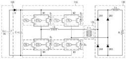
도 1은 본 발명의 일실시예에 따른 위상 천이형 풀브리지 컨버터에서 스위칭 소자를 개략적으로 설명하는 구성도이다.
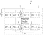
도 2는 본 발명의 일실시예에 따른 병렬 구조로 연결된 스위칭 소자를 설명하는 구성도이다.
도 3은 본 발명의 일실시예에 따른 스위칭 소자에 따른 효율을 설명하는 그래프이다.
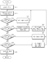
도 4는 본 발명의 일실시예에 따른 컨버터의 병렬 운전에 대한 제어 방법을 설명하는 도면이다.FIG. 1 is a configuration diagram schematically illustrating a switching device in a phase shift type full bridge converter according to an embodiment of the present invention. Referring to FIG.
2 is a block diagram illustrating a switching device connected in parallel according to an embodiment of the present invention.
3 is a graph illustrating efficiency according to a switching device according to an embodiment of the present invention.
4 is a view for explaining a control method for a parallel operation of a converter according to an embodiment of the present invention.
본 발명의 이점 및 특징, 그리고 그것을 달성하는 방법은 첨부되는 도면과 함께 상세하게 후술되어 있는 실시 예들을 통해 설명될 것이다. 그러나 본 발명은 여기에서 설명되는 실시 예들에 한정되지 않고 다른 형태로 구체화될 수도 있다. 단지, 본 실시 예들은 본 발명이 속하는 기술분야에서 통상의 지식을 가진 자에게 본 발명의 기술적 사상을 용이하게 실시할 수 있을 정도로 상세히 설명하기 위하여 제공되는 것이다.BRIEF DESCRIPTION OF THE DRAWINGS The advantages and features of the present invention, and how to accomplish it, will be described with reference to the embodiments described in detail below with reference to the accompanying drawings. However, the present invention is not limited to the embodiments described herein but may be embodied in other forms. The embodiments are provided so that those skilled in the art can easily carry out the technical idea of the present invention to those skilled in the art.
도면들에 있어서, 본 발명의 실시 예들은 도시된 특정 형태로 제한되는 것이 아니며 명확성을 기하기 위하여 과장된 것이다. 본 명세서에서 특정한 용어들이 사용되었으나. 이는 본 발명을 설명하기 위한 목적에서 사용된 것이며, 의미 한정이나 특허 청구 범위에 기재된 본 발명의 권리 범위를 제한하기 위하여 사용된 것은 아니다.In the drawings, embodiments of the present invention are not limited to the specific forms shown and are exaggerated for clarity. Although specific terms are used herein, It is to be understood that the same is by way of illustration and example only and is not to be taken by way of limitation of the scope of the appended claims.
본 명세서에서 '및/또는'이란 표현은 전후에 나열된 구성요소들 중 적어도 하나를 포함하는 의미로 사용된다. 또한, '연결되는/결합되는'이란 표현은 다른 구성요소와 직접적으로 연결되거나 다른 구성요소를 통해 간접적으로 연결되는 것을 포함하는 의미로 사용된다. 본 명세서에서 단수형은 문구에서 특별히 언급하지 않는 한 복수형도 포함한다. 또한, 명세서에서 사용되는 '포함한다' 또는 '포함하는'으로 언급된 구성요소, 단계, 동작 및 소자는 하나 이상의 다른 구성요소, 단계, 동작 및 소자의 존재 또는 추가를 의미한다.The expression " and / or " is used herein to mean including at least one of the elements listed before and after. Also, the expression " coupled / connected " is used to mean either directly connected to another component or indirectly connected through another component. The singular forms herein include plural forms unless the context clearly dictates otherwise. Also, as used herein, "comprising" or "comprising" means to refer to the presence or addition of one or more other components, steps, operations and elements.
이하의 설명에서 사용되는 구성요소에 대한 접미사 “모듈”, “부” 및 “소자”는 단순히 본 명세서 작성의 용이함을 고려하여 부여되는 것으로서, 상기 “모듈” 및 “부”는 서로 혼용되어 사용될 수도 있다.Module " and " device " for components used in the following description are given merely for ease of description in the present specification, and the " module " have.
이하, 도면들을 참조하여 본 발명의 실시 예에 대해 상세히 설명하기로 한다.Hereinafter, embodiments of the present invention will be described in detail with reference to the drawings.
도 1은 본 발명의 일실시예에 따른 위상 천이형 풀브리지 컨버터에서 스위칭 소자를 개략적으로 설명하는 구성도이다.FIG. 1 is a configuration diagram schematically illustrating a switching device in a phase shift type full bridge converter according to an embodiment of the present invention. Referring to FIG.
도 1을 참조하면, 위상 천이형 풀브리지 컨버터는 배터리 또는 AC-DC PFC 출력단이 연결되어 전원이 인가되는 입력부(100), 직류 전압을 교류 전압으로 변환시켜 주는 스위칭부(110), 절연 및 변압비에 따른 변압을 수행하기 위한 변압기(120), 교류 전압을 직류 전압으로 만들고, 전압 평활화를 위한 정류 및 필터부(130)로 구성된다. 여기서, 위상 천이형 풀브리지 컨버터는 변압기(120)를 기준으로 입력부(100) 및 스위칭부(110)를 포함하는 1차측 회로로 구성하고, 정류 및 필터부(130)를 포함하는 2차측 회로로 구성한다.1, the phase shift type full bridge converter includes an
구체적으로, 위상천이(Phase Shift) 제어에 따라 스위칭 신호를 수신하고, 경부하 시 진상 레그(Leading leg, LE) 및 지상 레그(Lagging leg, LA)에서 영전압 스위칭(ZVS)을 이루는 스위칭부(110)와, 스위칭부(110)의 출력 전압을 소정 레벨의 전압으로 출력하는 변압기(120) 및 변압기(120)로부터 전달된 교류 전압의 주파수 특성을 변환한 후에 주파수 특성이 변환된 교류전압을 직류전압으로 정류하고, 정류된 직류 전압을 필터링하는 정류 및 필터부(130)를 포함할 수 있다.More specifically, a switching unit that receives a switching signal in accordance with a phase shift control and performs zero voltage switching (ZVS) in a leading leg (LE) at a light load and a lagging leg (LA) A
도 2는 본 발명의 일실시예에 따른 병렬 구조로 연결된 스위칭 소자를 설명하는 구성도이다.2 is a block diagram illustrating a switching device connected in parallel according to an embodiment of the present invention.
도 2를 참조하면, 스위칭부(110)는 각 복수 개의 스위치로 구성되는 진상 레그회로(LE)와 지상 레그회로(LA)를 갖고, 진상 레그회로(LE) 및 지상 레그 회로(LA)는 상보적 관계를 갖도록 대향된다. 2, the
아울러, 스위칭부(110)는 입력 전압을 교번적으로 스위칭하여 직류 전압을 교류 전압으로 변환하여 변압기(120)에 전달한다.In addition, the
한편, 진상 레그회로(LE) 및 지상 레그회로(LA)는 각각 4개의 스위치((1a-1b, 2a-2b) 및 (1c-1d, 2c-2d))로 구성되며, 각 스위치(2a, 2b, 2c, 2d)는 각각으로 역병렬 다이오드(D1, D2, D3, D4)와 연결된다.The leading leg circuit LE and the ground leg circuit LA are each composed of four
여기서, 스위칭부(110)의 스위치(1a, 1b, 1c, 1d)는 제 1 모듈 또는 제 1 스위치 모듈로 정의하고, 스위치(2a, 2b, 2c, 2d)와 역병렬 다이오드(D1, D2, D3, D4)는 제 2 모듈 또는 제 2 스위치 모듈로 정의할 수 있다.The
제 1 모듈의 스위치는 제 2 모듈의 스위치와는 다르게 역병렬 다이오드가 존재하지 않는 특성을 가지고 있고, 이는 스위칭 동작 시에 역병렬 다이오드로 인한 손실이 없고, 영전압 스위칭을 원활하게 이루어지지 않는 저부하 영역에서 스위칭 손실을 크게 줄일 수 있다.Unlike the switch of the second module, the switch of the first module has a characteristic that there is no anti-parallel diode. This is because there is no loss due to the anti-parallel diode in the switching operation, The switching loss in the load region can be greatly reduced.
또한, 진상 레그회로(LE)의 두 스위치((1a-1b, 2a-2b)) 사이(A)와, 지상 레그회로(LA)의 두 스위치(1c-1d, 2c-2d) 사이(B)는 변압기(120)의 1차측 단자와 접속된다.It is also possible to set the distance between the two switches (1a-1b and 2a-2b) of the true leg leg circuit LE and the two
이와 같이 구성된 스위칭부(110)는 진상 레그회로(LE) 및 지상 레그회로(LA)는 소정 비율의 듀티비, 바람직하게는 50%의 듀티비를 갖고 상보적으로 동작되며, 출력은 진상 레그회로(LE)와 지상 레그회로(LA) 사이의 위상 천이(phase shift) 제어에 의해 결정된다.The
도 3은 본 발명의 일실시예에 따른 스위칭 소자에 따른 효율을 설명하는 그래프이다.3 is a graph illustrating efficiency according to a switching device according to an embodiment of the present invention.
도 3을 참조하면, 제 1 모듈(C)은 차량에서 요구되는 부하량(전장 부하량) 중 주 영역인 저부하의 효율을 향상시키기 위한 스위치이며, 제 2 모듈(D)은 차량에서 요구되는 부하량에서 중부하 및 고부하의 효율을 향상시키기 위한 스위치로써, 본 발명의 일실시예에 따른 스위칭 소자를 포함하는 위상 천이형 풀브리지 컨버터는 제 1 모듈(C)과 제 2 모듈(D)을 모두 이용하고, 제 1 모듈(C)과 제 2 모듈(D)을 병렬로 구성함으로써 차량에서 요구되는 부하량에서 저부하의 효율을 향상시킬 수 있고, 위상 천이형 풀브리지 컨버터의 전체적인 크기를 줄일 수 있다.Referring to FIG. 3, the first module C is a switch for improving the efficiency of a low load, which is a main area of the load amount (total load amount) required in the vehicle, and the second module D is a switch A phase shift type full bridge converter including a switching device according to an embodiment of the present invention uses both the first module C and the second module D as a switch for improving the efficiency of heavy load and high load , The first module (C) and the second module (D) are configured in parallel to improve the efficiency of the low load at the load amount required in the vehicle, and reduce the overall size of the phase shift type full bridge converter.
도 4는 본 발명의 일실시예에 따른 컨버터의 병렬 운전에 대한 제어 방법을 설명하는 도면이다.4 is a view for explaining a control method for a parallel operation of a converter according to an embodiment of the present invention.
도 4를 참조하면, 위상 천이형 풀브리지 컨버터가 동작한다(S11).Referring to FIG. 4, the phase shifting full bridge converter operates (S11).
다음으로, 차량은 컨버터 출력 제어 및 모듈 동작을 위한 차량에서 요구하는 부하량을 확인한다(S13).Next, the vehicle confirms the amount of load required by the vehicle for converter output control and module operation (S13).
다음으로, 차량은 차량에서 요구하는 부하량과 제 1 모듈에서의 최대 출력(P1)을 비교한다(S15). Next, the vehicle compares the load demanded by the vehicle with the maximum output P1 in the first module (S15).
다음으로, 차량에서 요구하는 부하량이 제 1 모듈에서의 최대 출력(P1)보다 작으면 제 1 모듈이 동작한다(S17). Next, if the load demanded by the vehicle is smaller than the maximum output P1 of the first module, the first module operates (S17).
그러나, 차량에서 요구하는 부하량이 제 1 모듈에서의 최대 출력(P1)보다 크면, 차량에서 요구된 부하량과 제 2 모듈에서의 최대 출력(P2)을 비교한다(S19). However, if the load demanded by the vehicle is larger than the maximum output P1 in the first module, the load required in the vehicle is compared with the maximum output P2 in the second module (S19).
다음에는, 차량에서 요구하는 부하량이 제 2 모듈에서의 최대 출력(P2)보다 작으면, 차량에서 요구하는 부하량을 분배하기 위한 계산을 실시하고, 컨버터의 효율을 극대화할 수 있도록 제 1 모듈과 제 2 모듈의 스위칭 제어를 서로 다르게 실시한다(S21~S23). Next, if the load demanded by the vehicle is smaller than the maximum output P2 of the second module, calculation is performed to distribute the load demanded by the vehicle, and the efficiency of the converter is maximized. The switching control of the two modules is performed differently (S21 to S23).
즉, 제 1 모듈의 최대 출력(P1)이 10이고, 제 2 모듈의 최대 출력(P2)이 90일 경우, 차량에서 요구하는 부하량이 15일 때와 30일 때의 출력 비율을 다르게 하는 것이며, 상세 출력 비율은 도 3에서와 같이 각각의 모듈에서의 효율을 설명하는 그래프에 대응한다. 일반적으로 각각의 모듈 별로 최대 출력의 30~40% 수준에서 효율이 극대화될 수 있다.That is, when the maximum output P1 of the first module is 10 and the maximum output P2 of the second module is 90, the output ratios at the time when the loads required by the vehicle are 15 and 30 are different, The detail output ratio corresponds to a graph describing the efficiency in each module as shown in FIG. In general, efficiency can be maximized at 30 ~ 40% of maximum output for each module.
다음으로, 차량에서 요구하는 부하량이 제 2 모듈에서의 최대 출력(P2)보다 크면, 차량에서 요구된 부하량과 제 1 모듈 및 제 2 모듈에서의 더해진 최대 출력(P3)을 비교한다(S25).Next, if the load demanded by the vehicle is greater than the maximum output (P2) in the second module, the load amount required in the vehicle is compared with the maximum output (P3) added in the first module and the second module (S25).
다음으로, 차량에서 요구하는 부하량이 제 1 모듈 및 제 2 모듈에서의 더해진 최대 출력(P3)보다 작으면, 제 2 모듈이 동작한다(S27).Next, if the load demanded by the vehicle is smaller than the maximum output P3 added in the first module and the second module, the second module operates (S27).
다음으로, 차량에서 요구하는 부하량이 제 1 모듈 및 제 2 모듈에서의 더해진 최대 출력(P3)보다 크면, 차량은 차량에서 요구하는 부하량이 없는지를 확인한다(S29). 즉, 차량은 컨버터의 출력 정지를 요청하는 것인지를 확인한다.Next, if the load demanded by the vehicle is larger than the maximum output P3 added in the first module and the second module, the vehicle confirms that there is no load required by the vehicle (S29). That is, the vehicle confirms whether the output of the converter is requested to be stopped.
다음으로, 차량에서 요구하는 부하량이 없을 경우에는 컨버터 출력을 정지한다(S31).Next, when there is no load required by the vehicle, the converter output is stopped (S31).
그러나, 차량에서 요구하는 부하량이 있을 경우에는 제 1 모듈과 제 2 모듈이 모두 동작한다. 이때, 차량은 컨버터의 출력 자체를 극대화할 수 있도록 최대 운전 동작으로 제어한다(S33). However, when there is a load demanded by the vehicle, both the first module and the second module operate. At this time, the vehicle is controlled to the maximum operation so as to maximize the output of the converter itself (S33).
전술한 바와 같이, 본 기술은 스위칭 소자를 병렬로 연결함에 따라 스위칭 소자의 고장에 대한 페일-세이프가 강화될 수 있다.As described above, the present technology can enhance the fail-safe against failure of the switching element by connecting the switching elements in parallel.
아울러, 본 기술은 반도체 소자 간 전류의 평형을 제어할 수 있고, 최대 효율 운전점의 동작이 가능한 기술이다.In addition, this technology is a technology capable of controlling the balance of current between semiconductor devices and operating the maximum efficiency operating point.
아울러, 본 기술은 스위칭 소자를 병렬로 연결하여 저부하에서의 전력 변환의 효율을 향상시킬 수 있는 기술이다.In addition, this technology is a technique that can improve the efficiency of power conversion at a low load by connecting the switching elements in parallel.
이상, 본 발명은 비록 한정된 구성과 도면에 의해 설명되었으나, 본 발명의 기술적 사상은 이러한 것에 한정되지 않으며, 본 발명이 속하는 기술분야에서 통상의 지식을 가진 자에 의해, 본 발명의 기술적 사상과 하기 기재될 특허청구범위의 균등범위 내에서 다양한 수정 및 변형 실시가 가능할 것이다.While the present invention has been particularly shown and described with reference to exemplary embodiments thereof, it is to be understood that the invention is not limited to the disclosed exemplary embodiments, but, on the contrary, Various modifications and variations may be made without departing from the scope of the appended claims.
Claims (14)
상기 제 1 모듈과 병렬 연결되어 복수 개로 구비된 제 2 모듈
을 포함하는 것을 특징으로 하는 스위칭 소자.A first module connected between a power source unit and a ground unit to which a power source of the vehicle is applied, the plurality of first modules; And
A second module connected in parallel with the first module,
And a switching element.
상기 제 1 모듈은 스위치가 구비된 것을 특징으로 하는 스위칭 소자.The method according to claim 1,
Wherein the first module is provided with a switch.
상기 제 2 모듈은 스위치와 다이오드가 구비된 것을 특징으로 하는 스위칭 소자.The method according to claim 1,
Wherein the second module comprises a switch and a diode.
상기 제 1 모듈 및 상기 제 2 모듈은 변압기를 통해 2차측 회로와 연결되는 것을 특징으로 하는 스위칭 소자.The method according to claim 1,
Wherein the first module and the second module are connected to a secondary circuit through a transformer.
상기 전원이 인가 되면, 상기 제 1 모듈 또는 상기 제 2 모듈만 동작하거나, 제 1 모듈 및 제 2 모듈이 동시에 동작하는 것을 특징으로 하는 스위칭 소자.The method according to claim 1,
Wherein when the power is applied, only the first module or the second module operates, or the first module and the second module operate simultaneously.
상기 차량에서 요구하는 부하량과 제 1 모듈에서의 최대 출력(P1)을 비교하는 단계;
상기 차량에서 요구하는 부하량이 제 1 모듈에서의 최대 출력(P1)보다 크면, 차량에서 요구된 부하량과 제 2 모듈에서의 최대 출력(P2)을 비교하는 단계;
상기 차량에서 요구하는 부하량이 제 2 모듈에서의 최대 출력(P2)보다 크면, 차량에서 요구된 부하량과 제 1 모듈 및 제 2 모듈에서의 더해진 최대 출력(P3)을 비교하는 단계; 및
상기 차량에서 요구하는 부하량이 제 1 모듈 및 제 2 모듈에서의 더해진 최대 출력(P3)보다 크면, 상기 차량에서 요구하는 부하량이 없는지를 확인하는 단계
를 포함하는 것을 특징으로 하는 스위칭 소자의 동작 방법.Checking a load amount required by the vehicle;
Comparing a load demanded by the vehicle with a maximum output P1 in the first module;
Comparing the load demanded in the vehicle with the maximum output (P2) in the second module if the load demanded by the vehicle is greater than the maximum output (P1) in the first module;
If the load demanded by the vehicle is greater than the maximum output (P2) in the second module, comparing the requested load in the vehicle with the first module and the added maximum output (P3) in the second module; And
If the load demanded by the vehicle is greater than the maximum output (P3) added in the first module and the second module, checking whether there is no load required by the vehicle
Wherein the switching element comprises a first switching element and a second switching element.
상기 차량에서 요구하는 부하량이 제 1 모듈에서의 최대 출력(P1)보다 작으면 제 1 모듈이 동작하는 단계를 포함하는 것을 특징으로 하는 스위칭 소자의 동작 방법.The method of claim 6,
And if the load demanded by the vehicle is less than a maximum output (P1) in the first module, operating the first module.
상기 제 1 모듈이 동작하는 단계에서,
복수 개의 스위치가 동작하는 것을 특징으로 하는 스위칭 소자의 동작 방법.The method of claim 7,
In the step of operating the first module,
Wherein a plurality of switches operate.
상기 차량에서 요구하는 부하량이 제 2 모듈에서의 최대 출력(P2)보다 작으면, 차량에서 요구하는 부하량을 분배하기 위한 계산을 실시하는 단계; 및
상기 제 1 모듈과 제 2 모듈의 스위칭 제어를 서로 다르게 실시하는 단계를 포함하는 것을 특징으로 하는 스위칭 소자의 동작 방법.The method of claim 6,
Performing a calculation for distributing a load amount demanded by the vehicle if the load demanded by the vehicle is smaller than the maximum output (P2) in the second module; And
And performing switching control of the first module and the second module differently from each other.
상기 차량에서 요구하는 부하량이 제 1 모듈 및 제 2 모듈에서의 더해진 최대 출력(P3)보다 작으면, 제 2 모듈이 동작하는 단계를 포함하는 것을 특징으로 하는 스위칭 소자의 동작 방법.The method of claim 6,
And if the load demanded by the vehicle is less than the maximum output (P3) added in the first module and the second module, operating the second module.
상기 제 2 모듈이 동작하는 단계에서,
복수 개의 스위치와 다이오드가 함께 동작하는 것을 특징으로 하는 스위칭 소자의 동작 방법.The method of claim 10,
In the step of operating the second module,
Wherein a plurality of switches and a diode operate together.
상기 차량에서 요구하는 부하량이 없을 경우에는 컨버터 출력을 정지하는 단계를 포함하는 것을 특징으로 하는 스위칭 소자의 동작 방법.The method of claim 6,
And stopping the output of the converter when there is no load required by the vehicle.
상기 차량에서 요구하는 부하량이 있을 경우에는 제 1 모듈과 제 2 모듈이 모두 동작하는 단계를 포함하는 것을 특징으로 하는 스위칭 소자의 동작 방법.The method of claim 6,
And when both the first module and the second module are operated when there is a load demanded by the vehicle.
상기 제 1 모듈 및 제 2 모듈은 변압기를 통해 2차측 회로와 연결되어 동작하는 것을 특징으로 하는 스위칭 소자의 동작 방법.The method of claim 6,
Wherein the first module and the second module are connected to a secondary circuit through a transformer.
Priority Applications (3)
| Application Number | Priority Date | Filing Date | Title |
|---|---|---|---|
| KR1020160069666A KR20170137478A (en) | 2016-06-03 | 2016-06-03 | Switching Device and Method for operating thereof |
| US15/347,270 US20170349052A1 (en) | 2016-06-03 | 2016-11-09 | Switching device and method for operating the same |
| CN201611069132.5A CN107465344A (en) | 2016-06-03 | 2016-11-28 | Switching device and its operating method |
Applications Claiming Priority (1)
| Application Number | Priority Date | Filing Date | Title |
|---|---|---|---|
| KR1020160069666A KR20170137478A (en) | 2016-06-03 | 2016-06-03 | Switching Device and Method for operating thereof |
Publications (1)
| Publication Number | Publication Date |
|---|---|
| KR20170137478A true KR20170137478A (en) | 2017-12-13 |
Family
ID=60482080
Family Applications (1)
| Application Number | Title | Priority Date | Filing Date |
|---|---|---|---|
| KR1020160069666A KR20170137478A (en) | 2016-06-03 | 2016-06-03 | Switching Device and Method for operating thereof |
Country Status (3)
| Country | Link |
|---|---|
| US (1) | US20170349052A1 (en) |
| KR (1) | KR20170137478A (en) |
| CN (1) | CN107465344A (en) |
Families Citing this family (1)
| Publication number | Priority date | Publication date | Assignee | Title |
|---|---|---|---|---|
| KR102489957B1 (en) * | 2018-04-04 | 2023-01-19 | 현대자동차주식회사 | Battery charger for electric vehicle |
Family Cites Families (12)
| Publication number | Priority date | Publication date | Assignee | Title |
|---|---|---|---|---|
| DE19532135A1 (en) * | 1995-08-31 | 1997-03-06 | Clouth Gummiwerke Ag | Drive system, in particular for a motor vehicle, and method for operating the same |
| JP4501893B2 (en) * | 2006-04-24 | 2010-07-14 | トヨタ自動車株式会社 | Power supply system and vehicle |
| JP4179383B2 (en) * | 2007-02-13 | 2008-11-12 | トヨタ自動車株式会社 | Driving force generation system, vehicle including the same, and control method thereof |
| EP2073364B1 (en) * | 2007-12-21 | 2013-07-24 | Honda Motor Co., Ltd. | Method of driving DC/DC converter and DC/DC converter |
| CN103189230B (en) * | 2010-10-28 | 2015-04-22 | 丰田自动车株式会社 | Power supply apparatus for electric vehicle, method of controlling power supply apparatus, and electric vehicle |
| US9306465B2 (en) * | 2011-06-10 | 2016-04-05 | Lear Corporation | Method for controlling a converter having variable frequency control and system for powering a vehicle load using same |
| EP3435389A1 (en) * | 2011-08-04 | 2019-01-30 | WiTricity Corporation | Tunable wireless power architectures |
| JP5940784B2 (en) * | 2011-09-09 | 2016-06-29 | 国立大学法人埼玉大学 | Non-contact power feeding device for moving objects |
| WO2013122703A1 (en) * | 2012-02-14 | 2013-08-22 | Ut-Battelle, Llc | Wireless power charging using point of load controlled high frequency power converters |
| CN104203639B (en) * | 2012-03-07 | 2016-10-26 | 丰田自动车株式会社 | Electric vehicle and control method thereof |
| US10566839B2 (en) * | 2015-06-30 | 2020-02-18 | WiTricinity Corporation | Systems, methods and apparatus for guidance and alignment between electric vehicles and wireless charging systems |
| US10879805B2 (en) * | 2015-09-22 | 2020-12-29 | Infineon Technologies Austria Ag | System and method for a switched-mode power supply having a transformer with a plurality of primary windings |
-
2016
- 2016-06-03 KR KR1020160069666A patent/KR20170137478A/en not_active Application Discontinuation
- 2016-11-09 US US15/347,270 patent/US20170349052A1/en not_active Abandoned
- 2016-11-28 CN CN201611069132.5A patent/CN107465344A/en active Pending
Also Published As
| Publication number | Publication date |
|---|---|
| US20170349052A1 (en) | 2017-12-07 |
| CN107465344A (en) | 2017-12-12 |
Similar Documents
| Publication | Publication Date | Title |
|---|---|---|
| Han et al. | A new active clamping zero-voltage switching PWM current-fed half-bridge converter | |
| JP5558631B2 (en) | Power conversion device and in-vehicle power supply device including the same | |
| KR100810707B1 (en) | Converter | |
| US20040179381A1 (en) | Two-way DC-DC converter | |
| KR101191137B1 (en) | Bi-Directional Charging System | |
| JP2008079454A (en) | Method of controlling bidirectional dc-dc converter | |
| KR20160016636A (en) | Three port dc-dc converter | |
| JP2015159711A (en) | Switching power supply and power converter | |
| CN105141134A (en) | Switch power supply and method for controlling switch power supply | |
| KR101314903B1 (en) | Bidirectional dc/dc converter | |
| Song et al. | A three-switch-based single-input dual-output converter with simultaneous boost & buck voltage conversion | |
| Rezaii et al. | Design and experimental study of a high voltage gain bidirectional DC-DC converter for electrical vehicle application | |
| WO2022059294A1 (en) | Power conversion device | |
| US9954452B2 (en) | Low voltage direct current (DC)-DC converter | |
| CN108599346A (en) | A kind of three-level formula electric vehicle charging circuit and its control method | |
| KR20170137478A (en) | Switching Device and Method for operating thereof | |
| CN107017776A (en) | New isolation type active clamping alternation parallel Boost soft switch transducers and method of work | |
| JP2016025831A (en) | Auxiliary circuit of dc-dc converter, and bidirectional step-up/down dc-dc converter arranged by use thereof | |
| KR100911541B1 (en) | Bi-Directional Tri-State PWM DC To DC Converter For Fuel Cell Vehicle | |
| US20230322105A1 (en) | Charging device and method for operating the charging device | |
| JP2022049533A (en) | Power converter | |
| Wilson et al. | Partial power converter for dcx-based high-power led drivers | |
| TWI399122B (en) | Single-state led driving circuit with zero voltage switching | |
| JPWO2012017753A1 (en) | Power converter | |
| TWI645650B (en) | Electric vehicle power supply system and multi-power supply method |
Legal Events
| Date | Code | Title | Description |
|---|---|---|---|
| A201 | Request for examination | ||
| E902 | Notification of reason for refusal | ||
| E601 | Decision to refuse application |