EP2823979B1 - Tie rod, plastic tank and method for the preparation of a plastic tank - Google Patents
Tie rod, plastic tank and method for the preparation of a plastic tank Download PDFInfo
- Publication number
- EP2823979B1 EP2823979B1 EP13175893.0A EP13175893A EP2823979B1 EP 2823979 B1 EP2823979 B1 EP 2823979B1 EP 13175893 A EP13175893 A EP 13175893A EP 2823979 B1 EP2823979 B1 EP 2823979B1
- Authority
- EP
- European Patent Office
- Prior art keywords
- plastic
- tie rod
- tank
- plastic tank
- end faces
- Prior art date
- Legal status (The legal status is an assumption and is not a legal conclusion. Google has not performed a legal analysis and makes no representation as to the accuracy of the status listed.)
- Not-in-force
Links
Images

Classifications
-
- B—PERFORMING OPERATIONS; TRANSPORTING
- B60—VEHICLES IN GENERAL
- B60K—ARRANGEMENT OR MOUNTING OF PROPULSION UNITS OR OF TRANSMISSIONS IN VEHICLES; ARRANGEMENT OR MOUNTING OF PLURAL DIVERSE PRIME-MOVERS IN VEHICLES; AUXILIARY DRIVES FOR VEHICLES; INSTRUMENTATION OR DASHBOARDS FOR VEHICLES; ARRANGEMENTS IN CONNECTION WITH COOLING, AIR INTAKE, GAS EXHAUST OR FUEL SUPPLY OF PROPULSION UNITS IN VEHICLES
- B60K15/00—Arrangement in connection with fuel supply of combustion engines or other fuel consuming energy converters, e.g. fuel cells; Mounting or construction of fuel tanks
- B60K15/03—Fuel tanks
- B60K15/03006—Gas tanks
-
- B—PERFORMING OPERATIONS; TRANSPORTING
- B60—VEHICLES IN GENERAL
- B60K—ARRANGEMENT OR MOUNTING OF PROPULSION UNITS OR OF TRANSMISSIONS IN VEHICLES; ARRANGEMENT OR MOUNTING OF PLURAL DIVERSE PRIME-MOVERS IN VEHICLES; AUXILIARY DRIVES FOR VEHICLES; INSTRUMENTATION OR DASHBOARDS FOR VEHICLES; ARRANGEMENTS IN CONNECTION WITH COOLING, AIR INTAKE, GAS EXHAUST OR FUEL SUPPLY OF PROPULSION UNITS IN VEHICLES
- B60K15/00—Arrangement in connection with fuel supply of combustion engines or other fuel consuming energy converters, e.g. fuel cells; Mounting or construction of fuel tanks
- B60K15/03—Fuel tanks
- B60K15/03177—Fuel tanks made of non-metallic material, e.g. plastics, or of a combination of non-metallic and metallic material
-
- B—PERFORMING OPERATIONS; TRANSPORTING
- B65—CONVEYING; PACKING; STORING; HANDLING THIN OR FILAMENTARY MATERIAL
- B65D—CONTAINERS FOR STORAGE OR TRANSPORT OF ARTICLES OR MATERIALS, e.g. BAGS, BARRELS, BOTTLES, BOXES, CANS, CARTONS, CRATES, DRUMS, JARS, TANKS, HOPPERS, FORWARDING CONTAINERS; ACCESSORIES, CLOSURES, OR FITTINGS THEREFOR; PACKAGING ELEMENTS; PACKAGES
- B65D23/00—Details of bottles or jars not otherwise provided for
- B65D23/001—Supporting means fixed to the container
-
- B—PERFORMING OPERATIONS; TRANSPORTING
- B65—CONVEYING; PACKING; STORING; HANDLING THIN OR FILAMENTARY MATERIAL
- B65D—CONTAINERS FOR STORAGE OR TRANSPORT OF ARTICLES OR MATERIALS, e.g. BAGS, BARRELS, BOTTLES, BOXES, CANS, CARTONS, CRATES, DRUMS, JARS, TANKS, HOPPERS, FORWARDING CONTAINERS; ACCESSORIES, CLOSURES, OR FITTINGS THEREFOR; PACKAGING ELEMENTS; PACKAGES
- B65D90/00—Component parts, details or accessories for large containers
- B65D90/02—Wall construction
- B65D90/08—Interconnections of wall parts; Sealing means therefor
-
- F—MECHANICAL ENGINEERING; LIGHTING; HEATING; WEAPONS; BLASTING
- F17—STORING OR DISTRIBUTING GASES OR LIQUIDS
- F17C—VESSELS FOR CONTAINING OR STORING COMPRESSED, LIQUEFIED OR SOLIDIFIED GASES; FIXED-CAPACITY GAS-HOLDERS; FILLING VESSELS WITH, OR DISCHARGING FROM VESSELS, COMPRESSED, LIQUEFIED, OR SOLIDIFIED GASES
- F17C1/00—Pressure vessels, e.g. gas cylinder, gas tank, replaceable cartridge
- F17C1/16—Pressure vessels, e.g. gas cylinder, gas tank, replaceable cartridge constructed of plastics materials
-
- B—PERFORMING OPERATIONS; TRANSPORTING
- B29—WORKING OF PLASTICS; WORKING OF SUBSTANCES IN A PLASTIC STATE IN GENERAL
- B29C—SHAPING OR JOINING OF PLASTICS; SHAPING OF MATERIAL IN A PLASTIC STATE, NOT OTHERWISE PROVIDED FOR; AFTER-TREATMENT OF THE SHAPED PRODUCTS, e.g. REPAIRING
- B29C49/00—Blow-moulding, i.e. blowing a preform or parison to a desired shape within a mould; Apparatus therefor
- B29C49/20—Blow-moulding, i.e. blowing a preform or parison to a desired shape within a mould; Apparatus therefor of articles having inserts or reinforcements ; Handling of inserts or reinforcements
- B29C2049/2008—Blow-moulding, i.e. blowing a preform or parison to a desired shape within a mould; Apparatus therefor of articles having inserts or reinforcements ; Handling of inserts or reinforcements inside the article
- B29C2049/2013—Blow-moulding, i.e. blowing a preform or parison to a desired shape within a mould; Apparatus therefor of articles having inserts or reinforcements ; Handling of inserts or reinforcements inside the article for connecting opposite walls, e.g. baffles in a fuel tank
-
- B—PERFORMING OPERATIONS; TRANSPORTING
- B29—WORKING OF PLASTICS; WORKING OF SUBSTANCES IN A PLASTIC STATE IN GENERAL
- B29C—SHAPING OR JOINING OF PLASTICS; SHAPING OF MATERIAL IN A PLASTIC STATE, NOT OTHERWISE PROVIDED FOR; AFTER-TREATMENT OF THE SHAPED PRODUCTS, e.g. REPAIRING
- B29C51/00—Shaping by thermoforming, i.e. shaping sheets or sheet like preforms after heating, e.g. shaping sheets in matched moulds or by deep-drawing; Apparatus therefor
- B29C51/12—Shaping by thermoforming, i.e. shaping sheets or sheet like preforms after heating, e.g. shaping sheets in matched moulds or by deep-drawing; Apparatus therefor of articles having inserts or reinforcements
-
- B—PERFORMING OPERATIONS; TRANSPORTING
- B29—WORKING OF PLASTICS; WORKING OF SUBSTANCES IN A PLASTIC STATE IN GENERAL
- B29L—INDEXING SCHEME ASSOCIATED WITH SUBCLASS B29C, RELATING TO PARTICULAR ARTICLES
- B29L2031/00—Other particular articles
- B29L2031/712—Containers; Packaging elements or accessories, Packages
- B29L2031/7172—Fuel tanks, jerry cans
-
- B—PERFORMING OPERATIONS; TRANSPORTING
- B60—VEHICLES IN GENERAL
- B60K—ARRANGEMENT OR MOUNTING OF PROPULSION UNITS OR OF TRANSMISSIONS IN VEHICLES; ARRANGEMENT OR MOUNTING OF PLURAL DIVERSE PRIME-MOVERS IN VEHICLES; AUXILIARY DRIVES FOR VEHICLES; INSTRUMENTATION OR DASHBOARDS FOR VEHICLES; ARRANGEMENTS IN CONNECTION WITH COOLING, AIR INTAKE, GAS EXHAUST OR FUEL SUPPLY OF PROPULSION UNITS IN VEHICLES
- B60K15/00—Arrangement in connection with fuel supply of combustion engines or other fuel consuming energy converters, e.g. fuel cells; Mounting or construction of fuel tanks
- B60K15/03—Fuel tanks
- B60K2015/03032—Manufacturing of fuel tanks
- B60K2015/03039—Manufacturing of fuel tanks made of a combination of non metallic and metallic materials
-
- B—PERFORMING OPERATIONS; TRANSPORTING
- B60—VEHICLES IN GENERAL
- B60K—ARRANGEMENT OR MOUNTING OF PROPULSION UNITS OR OF TRANSMISSIONS IN VEHICLES; ARRANGEMENT OR MOUNTING OF PLURAL DIVERSE PRIME-MOVERS IN VEHICLES; AUXILIARY DRIVES FOR VEHICLES; INSTRUMENTATION OR DASHBOARDS FOR VEHICLES; ARRANGEMENTS IN CONNECTION WITH COOLING, AIR INTAKE, GAS EXHAUST OR FUEL SUPPLY OF PROPULSION UNITS IN VEHICLES
- B60K15/00—Arrangement in connection with fuel supply of combustion engines or other fuel consuming energy converters, e.g. fuel cells; Mounting or construction of fuel tanks
- B60K15/03—Fuel tanks
- B60K2015/03328—Arrangements or special measures related to fuel tanks or fuel handling
- B60K2015/03453—Arrangements or special measures related to fuel tanks or fuel handling for fixing or mounting parts of the fuel tank together
-
- Y—GENERAL TAGGING OF NEW TECHNOLOGICAL DEVELOPMENTS; GENERAL TAGGING OF CROSS-SECTIONAL TECHNOLOGIES SPANNING OVER SEVERAL SECTIONS OF THE IPC; TECHNICAL SUBJECTS COVERED BY FORMER USPC CROSS-REFERENCE ART COLLECTIONS [XRACs] AND DIGESTS
- Y10—TECHNICAL SUBJECTS COVERED BY FORMER USPC
- Y10T—TECHNICAL SUBJECTS COVERED BY FORMER US CLASSIFICATION
- Y10T156/00—Adhesive bonding and miscellaneous chemical manufacture
- Y10T156/10—Methods of surface bonding and/or assembly therefor
Definitions
- the present invention relates to a tie rod for a plastic tank.
- the invention also relates to a plastic tank with such a tie rod and a method for producing such a plastic tank.
- Plastic tanks in particular pressure plastic fuel tanks (DKKB), are known to be equipped with tie rods for receiving tensile forces acting on the tank shells.
- the tie rods are usually made of the same material as the tank shells, in particular of high density polyethylene (HDPE). Tie rods made of HDPE can be welded into the tank shells during production and are therefore inexpensive to manufacture.
- HDPE high density polyethylene
- a tie rod made of plastic for example, from the US 6 338 420 B1 known.
- Plastic tie rods show a swelling behavior under the action of fuel, so that the tie rods and herewith also the plastic tanks are deformed over time.
- a fuel tank with a reinforcing element is known, wherein the reinforcing element has a hollow column.
- the column can consist of two different materials.
- a container is known which is manufactured by rotational molding, comprising an inner support which is attached during the casting process.
- the US 2002/100759 A1 discloses an internal reinforcing structure of a plastic container wherein walls of the container form an inwardly projecting recess.
- a tie rod for a plastic tank wherein the tie rod end faces of plastic and has between the front end faces a middle part of a metal, wherein the front end faces the statements represent of frontal end portions, wherein the central part is a metal rod and the end portions are formed by perforated plates, which are molded with plastic.
- a tie rod although plastic end surfaces, and is thus easily connectable to the plastic tank, in particular welded to the tank shell of the plastic tank.
- the tie rod is inventively not made of plastic, but has a middle part of metal, which is much less prone to deformation with prolonged exposure to fuel as a corresponding plastic part.
- the object is also achieved by a plastic tank, wherein the plastic tank has a plastic tank shell and at least one tie rod according to the invention.
- the tank shell can consist in particular of HDPE.
- the object is also achieved by a method for producing such a plastic tank, wherein the end faces of the tie rod are welded in the production of the tank shell with this. This allows a particularly cost-effective production of a dimensionally stable plastic tank.
- the end-side end faces represent the terminations of end-side end sections of the tie rods.
- the end portions and / or the end surfaces may be made of the same plastic as the tank shell of the plastic tank.
- the plastic may be polyethylene, preferably high density polyethylene (HDPE).
- HDPE high density polyethylene
- the middle part of the tie rod is a metal rod. This can be made thin and displaced by this geometry little tank volume with good strength.
- the end sections of the tie rod are formed by perforated plates which are encapsulated in plastic.
- a simple connection between metal and plastic of the tie rod is made while ensuring a low weight of the tie rod.
- a tie rod with such end portions used according to the invention a metal rod as a central part.
- a known tie rod is shown.
- the tie rod is made in one piece from HDPE.
- the front end faces 1 and 2 of the tie rod therefore also consist of HDPE and can be welded to a plastic tank.
- the middle part 3 of the tie rod is a HDPE solid material.
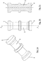
- Fig. 2a, b and c show a tie rod according to the invention.
- the tie rod has front end faces 1, 2 made of plastic and between the front end faces 1, 2 a middle part 3 made of a metal.
- a thin metal rod 6 is used as the middle part 3, which has perforated plates 9 at both ends.
- Holes 12 are for example distributed rotationally symmetrically on the perforated plates 9.
- the perforated plates 9 are encapsulated with plastic, so that in each case a perforated plate 9 and a plastic extrusion together form an end portion 4, 5.
- the end surfaces 1 and 2 of the end sections 4 and 5 are therefore made of plastic, in particular HDPE.
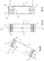
- a metal tube 7 with openings 8 is used as a central part 3, a metal tube 7 with openings 8.
- the openings 8 are designed as slots, which are distributed at axially and circumferentially different positions on the metal tube 7. Through these openings 8 fuel can reach the interior of the metal tube 7, so that its volume displaces only a small volume of tank.
- the end sections 4, 5 of the tie rod are here designed as HDPE injection molded parts 10, which are crimped onto the ends of the metal tube 7.
- the injection-molded parts 10 can also have supporting sleeves 13 arranged in the center of the injection-molded parts for stiffening purposes.
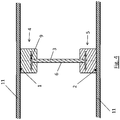
- Fig. 4 finally shows a tie rod according to the invention, accordingly Fig. 2c , built into a plastic tank.
- the plastic tank has an upper and a lower tank shell 11 of HDPE. Welded on both sides with the tank shell are the end faces 1 and 2 of the tie rod according to the invention.
Description
Die vorliegende Erfindung betrifft einen Zuganker für einen Kunststofftank. Die Erfindung betrifft auch einen Kunststofftank mit einem solchen Zuganker und ein Verfahren zur Herstellung eines solchen Kunststofftanks.The present invention relates to a tie rod for a plastic tank. The invention also relates to a plastic tank with such a tie rod and a method for producing such a plastic tank.
Kunststofftanks, insbesondere Druckkunststoffkraftstofftanks (DKKB), werden zur Aufnahme von auf die Tankschalen einwirkenden Zugkräften bekannterweise mit Zugankern ausgestattet. Die Zuganker werden üblicherweise aus dem selben Material wie die Tankschalen gefertigt, insbesondere aus High Density Polyethylen (HDPE). Zuganker aus HDPE können bei der Herstellung der Tankschalen in diese eingeschweißt werden und sind daher kostengünstig zu fertigen.Plastic tanks, in particular pressure plastic fuel tanks (DKKB), are known to be equipped with tie rods for receiving tensile forces acting on the tank shells. The tie rods are usually made of the same material as the tank shells, in particular of high density polyethylene (HDPE). Tie rods made of HDPE can be welded into the tank shells during production and are therefore inexpensive to manufacture.
Ein Zuganker aus Kunststoff ist beispielsweise aus der
Zuganker aus Kunststoff zeigen jedoch unter Kraftstoffeinwirkung ein Quellverhalten, sodass die Zuganker und hiermit auch die Kunststofftanks im Lauf der Zeit verformt werden.Plastic tie rods, however, show a swelling behavior under the action of fuel, so that the tie rods and herewith also the plastic tanks are deformed over time.
Aus der gattungsbildenden
Die
Es ist eine Aufgabe der Erfindung, Zuganker für Kunststofftanks zu verbessern und insbesondere Zuganker anzugeben, die verbesserte Langzeiteigenschaften unter Kraftstoffeinwirkung aufweisen, die weniger zu Verformungen neigen, die geringen Bauraumbedarf und geringes Gewicht haben und einfach herstellbar sind. Es ist auch eine Aufgabe der Erfindung einen verbesserten Kunststofftank und ein Verfahren zur Herstellung eines Kunststofftanks anzugeben.It is an object of the invention to improve tie rods for plastic tanks and in particular to provide tie rods which have improved long-term fuel properties, which are less prone to deformation, have low space requirements and low weight and are easy to produce. It is also an object of the invention to provide an improved plastic tank and a method of manufacturing a plastic tank.
Die Lösung der Aufgabe erfolgt durch einen Zuganker für einen Kunststofftank, wobei der Zuganker stirnseitige Endflächen aus Kunststoff aufweist und zwischen den stirnseitigen Endflächen einen Mittelteil aus einem Metall aufweist, wobei die stirnseitigen Endflächen die Abschlüsse von stirnseitigen Endabschnitten darstellen, wobei der Mittelteil ein Metallstab ist und die Endabschnitte durch Lochbleche gebildet sind, die mit Kunststoff umspritzt sind.The object is achieved by a tie rod for a plastic tank, wherein the tie rod end faces of plastic and has between the front end faces a middle part of a metal, wherein the front end faces the statements represent of frontal end portions, wherein the central part is a metal rod and the end portions are formed by perforated plates, which are molded with plastic.
Erfindungsgemäß weist ein Zuganker zwar Endflächen aus Kunststoff auf, und ist somit einfach mit dem Kunststofftank verbindbar, insbesondere mit der Tankschale des Kunststofftanks verschweißbar. Der Zuganker ist aber erfindungsgemäß nicht durchgängig aus Kunststoff gefertigt, sondern weist einen Mittelteil aus Metall auf, der weitaus weniger zu Verformungen bei längerer Einwirkung von Kraftstoff neigt als ein entsprechender Kunststoffteil.According to the invention, a tie rod, although plastic end surfaces, and is thus easily connectable to the plastic tank, in particular welded to the tank shell of the plastic tank. However, the tie rod is inventively not made of plastic, but has a middle part of metal, which is much less prone to deformation with prolonged exposure to fuel as a corresponding plastic part.
Die Lösung der Aufgabe erfolgt auch durch einen Kunststofftank, wobei der Kunststofftank eine Tankschale aus Kunststoff und zumindest einen erfindungsgemäßen Zuganker aufweist. Die Tankschale kann dabei insbesondere aus HDPE bestehen.The object is also achieved by a plastic tank, wherein the plastic tank has a plastic tank shell and at least one tie rod according to the invention. The tank shell can consist in particular of HDPE.
Die Lösung der Aufgabe erfolgt auch durch ein Verfahren zur Herstellung eines solchen Kunststofftanks, wobei die Endflächen des Zugankers bei der Herstellung der Tankschale mit dieser verschweißt werden. Dadurch wird eine besonders kostengünstige Herstellung eines formstabilen Kunststofftanks ermöglicht.The object is also achieved by a method for producing such a plastic tank, wherein the end faces of the tie rod are welded in the production of the tank shell with this. This allows a particularly cost-effective production of a dimensionally stable plastic tank.
Weiterbildungen der Erfindung sind in den abhängigen Ansprüchen, der Beschreibung sowie den beigefügten Zeichnungen angegeben.Further developments of the invention are specified in the dependent claims, the description and the accompanying drawings.
Erfindungsgemäß stellen die stirnseitigen Endflächen die Abschlüsse von stirnseitigen Endabschnitten der Zuganker dar.According to the invention, the end-side end faces represent the terminations of end-side end sections of the tie rods.
Dabei können die Endabschnitte und/oder die Endflächen aus dem selben Kunststoff bestehen, wie die Tankschale des Kunststofftanks.In this case, the end portions and / or the end surfaces may be made of the same plastic as the tank shell of the plastic tank.
Insbesondere kann der Kunststoff Polyethylen, bevorzugt High Density Polyethylen (HDPE) sein.In particular, the plastic may be polyethylene, preferably high density polyethylene (HDPE).
Erfindungsgemäß ist der Mittelteil des Zugankers ein Metallstab. Dieser kann dünn ausgeführt sein und verdrängt durch diese Geometrie wenig Tankvolumen bei guter Festigkeit.According to the invention, the middle part of the tie rod is a metal rod. This can be made thin and displaced by this geometry little tank volume with good strength.
Erfindungsgemäß sind die Endabschnitte des Zugankers durch Lochbleche gebildet, die mit Kunststoff umspritzt sind. Auf diese Weise wird eine einfache Verbindung zwischen Metall und Kunststoff des Zugankers hergestellt und dabei ein geringes Gewicht des Zugankers gewährleistet. Ein Zuganker mit derartigen Endabschnitten verwendet erfindungsgemäß einen Metallstab als Mittelteil.According to the invention, the end sections of the tie rod are formed by perforated plates which are encapsulated in plastic. In this way, a simple connection between metal and plastic of the tie rod is made while ensuring a low weight of the tie rod. A tie rod with such end portions used according to the invention a metal rod as a central part.
Die Erfindung wird im Folgenden beispielhaft unter Bezugnahme auf die Zeichnungen beschrieben.
- Fig. 1a
- ist eine dreidimensionale Darstellung eines Zugankers aus dem Stand der Technik.
- Fig. 1b
- ist eine Vorderansicht eines Zugankers gemäß
Fig. 1a . - Fig. 1c
- ist eine Schnittansicht eines Zugankers gemäß A-A der
Fig. 1b . - Fig. 2a
- ist eine dreidimensionale Darstellung eines erfindungsgemäßen Zugankers nach einer ersten Ausführungsform.
- Fig. 2b
- ist eine Vorderansicht eines Zugankers gemäß
Fig. 2a . - Fig. 2c
- ist eine Schnittansicht eines Zugankers gemäß A-A der
Fig. 2b . - Fig. 3a
- ist eine dreidimensionale Darstellung eines nicht erfindungsgemäßen Zugankers.
- Fig. 3b
- ist eine Vorderansicht eines Zugankers gemäß
Fig. 3a . - Fig. 3c
- ist eine Schnittansicht eines Zugankers gemäß A-A der
Fig. 3b . - Fig. 4
- ist eine Schnittansicht eines Teiles eines erfindungsgemäßen Kunststofftanks mit einem Zuganker gem.
Fig. 2c .
- Fig. 1a
- is a three-dimensional representation of a tie rod from the prior art.
- Fig. 1b
- is a front view of a tie rod according to
Fig. 1a , - Fig. 1c
- is a sectional view of a tie rod according to AA of
Fig. 1b , - Fig. 2a
- is a three-dimensional view of a tie rod according to the invention according to a first embodiment.
- Fig. 2b
- is a front view of a tie rod according to
Fig. 2a , - Fig. 2c
- is a sectional view of a tie rod according to AA of
Fig. 2b , - Fig. 3a
- is a three-dimensional view of a tie rod not according to the invention.
- Fig. 3b
- is a front view of a tie rod according to
Fig. 3a , - Fig. 3c
- is a sectional view of a tie rod according to AA of
Fig. 3b , - Fig. 4
- is a sectional view of a part of a plastic tank according to the invention with a tie rod gem.
Fig. 2c ,
In
In der nicht erfindungsgemäßen Ausführungsform der
- 11
- Endflächeend face
- 22
- Endflächeend face
- 33
- Mittelteilmidsection
- 44
- Endabschnittend
- 55
- Endabschnittend
- 66
- Metallstabmetal rod
- 77
- Metallrohrmetal pipe
- 88th
- Öffnungopening
- 99
- Lochblechperforated sheet
- 1010
- Spritzgussteilinjection molding
- 1111
- Tankschaletank shell
- 1212
- Lochhole
- 1313
- Stützhülsesupport sleeve
Claims (4)
- Tie rod for a plastic tank,
wherein the tie rod has end faces (1, 2) made of plastic and between the end faces (1, 2) has a central part (3) made of a metal, wherein the end faces (1, 2) represent the terminations of end portions (4, 5), characterized in that the central part (3) is a metal bar (6) and the end portions (4, 5) are formed by perforated metal plates (9), which are encapsulated with plastic by injection moulding. - Tie rod according to Claim 1,
characterized in that the plastic is high density polyethylene. - Plastic tank,
characterized in that the plastic tank has a tank shell (11) made of plastic and at least one tie rod according to at least one of the preceding claims. - Process for producing a plastic tank according to Claim 3,
characterized in that the end faces (1, 2) of the tie rod are welded to the tank shell (11) during the production of the latter.
Priority Applications (3)
| Application Number | Priority Date | Filing Date | Title |
|---|---|---|---|
| EP13175893.0A EP2823979B1 (en) | 2013-07-10 | 2013-07-10 | Tie rod, plastic tank and method for the preparation of a plastic tank |
| US14/323,233 US9090156B2 (en) | 2013-07-10 | 2014-07-03 | Tie rod, plastic tank and method for manufacturing a plastic tank |
| CN201410319960.4A CN104276032A (en) | 2013-07-10 | 2014-07-07 | Tie rod, plastic tank and method for manufacturing plastic tank |
Applications Claiming Priority (1)
| Application Number | Priority Date | Filing Date | Title |
|---|---|---|---|
| EP13175893.0A EP2823979B1 (en) | 2013-07-10 | 2013-07-10 | Tie rod, plastic tank and method for the preparation of a plastic tank |
Publications (2)
| Publication Number | Publication Date |
|---|---|
| EP2823979A1 EP2823979A1 (en) | 2015-01-14 |
| EP2823979B1 true EP2823979B1 (en) | 2017-05-03 |
Family
ID=48914046
Family Applications (1)
| Application Number | Title | Priority Date | Filing Date |
|---|---|---|---|
| EP13175893.0A Not-in-force EP2823979B1 (en) | 2013-07-10 | 2013-07-10 | Tie rod, plastic tank and method for the preparation of a plastic tank |
Country Status (3)
| Country | Link |
|---|---|
| US (1) | US9090156B2 (en) |
| EP (1) | EP2823979B1 (en) |
| CN (1) | CN104276032A (en) |
Cited By (1)
| Publication number | Priority date | Publication date | Assignee | Title |
|---|---|---|---|---|
| KR102264640B1 (en) | 2013-10-25 | 2021-06-14 | 플라스틱 옴니엄 어드벤스드 이노베이션 앤드 리서치 | Tank comprising a reinforcement member and method for manufacturing such a reinforcement member |
Families Citing this family (13)
| Publication number | Priority date | Publication date | Assignee | Title |
|---|---|---|---|---|
| DE102012019334A1 (en) * | 2012-10-02 | 2014-04-03 | Kautex Textron Gmbh & Co. Kg | Container made of thermoplastic material |
| EP2823979B1 (en) * | 2013-07-10 | 2017-05-03 | Magna Steyr Fuel Systems GesmbH | Tie rod, plastic tank and method for the preparation of a plastic tank |
| CN105235501A (en) * | 2015-10-22 | 2016-01-13 | 麦格纳斯太尔汽车技术(上海)有限公司 | High-pressure automobile fuel tank made of plastic |
| JP6519465B2 (en) * | 2015-12-25 | 2019-05-29 | トヨタ自動車株式会社 | Fuel tank |
| DE102016204648A1 (en) | 2016-03-21 | 2017-09-21 | Kautex Textron Gmbh & Co. Kg | Operating fluid container with stiffening element and method for producing an operating fluid container |
| US20180037105A1 (en) * | 2016-08-04 | 2018-02-08 | Ford Global Technologies, Llc | Reinforced fuel tank |
| DE102016219539A1 (en) * | 2016-10-07 | 2018-04-12 | Kautex Textron Gmbh & Co. Kg | Stiffening element for a fluid container for a motor vehicle and fluid container for a motor vehicle with a stiffening element |
| KR20180001136U (en) * | 2016-10-14 | 2018-04-24 | 박연주 | Hook built-in discoid lpg container for vehicles |
| EP3339075A1 (en) * | 2016-12-23 | 2018-06-27 | Plastic Omnium Advanced Innovation and Research | Plastic vehicle tank with connecting element having an improved breaking effect |
| JP6943721B2 (en) * | 2017-10-12 | 2021-10-06 | トヨタ自動車株式会社 | Fuel tank |
| US11618314B2 (en) * | 2018-04-24 | 2023-04-04 | Yapp Automotive Systems Co., Ltd. | Support for connecting upper and lower surfaces inside fuel tank |
| KR102621556B1 (en) * | 2019-05-22 | 2024-01-04 | 현대자동차주식회사 | Stiffness reinforcement structure for fuel tank of vehicle |
| US11603228B2 (en) * | 2019-10-10 | 2023-03-14 | P.R.A. Company | Reusable recyclable thermoformed shipping containers |
Family Cites Families (18)
| Publication number | Priority date | Publication date | Assignee | Title |
|---|---|---|---|---|
| US2407455A (en) * | 1942-04-03 | 1946-09-10 | Ici Ltd | Liquid container |
| US3368708A (en) * | 1966-07-28 | 1968-02-13 | Smith Corp A O | Filament wound tank design |
| US3774812A (en) * | 1972-02-03 | 1973-11-27 | J Lemelson | Molded container with internal su port means |
| US5813566A (en) * | 1995-07-12 | 1998-09-29 | Bradford Company | Damage resistant container and sleeve pack assembly |
| US6135306A (en) * | 1999-02-08 | 2000-10-24 | Salflex Polymers Inc. | Fuel tank anti-deflection device |
| US6138859A (en) * | 1999-06-08 | 2000-10-31 | Delphi Technologies, Inc. | Fuel tank assembly |
| US6338420B1 (en) | 1999-06-08 | 2002-01-15 | Delphi Technologies, Inc. | Motor vehicle fuel tank and method |
| DE10104511A1 (en) * | 2001-01-31 | 2002-08-29 | Ti Group Automotive Systems Te | Fuel tank with tie rod |
| DE10329990B3 (en) * | 2003-07-02 | 2005-04-21 | Benteler Automobiltechnik Gmbh | Pressure gas tank |
| US7059305B2 (en) * | 2003-07-21 | 2006-06-13 | Automotive Components Holdings, Llc | Internalized component for fuel tanks |
| US7455190B2 (en) * | 2004-11-15 | 2008-11-25 | Automotive Components Holdings, Llc | Fuel tank system having enhanced durability and reduced permeation |
| AU2009243485B2 (en) * | 2009-12-02 | 2015-12-03 | Bluescope Steel Limited | Internal tie for a fluid storage tank |
| DE102010036683A1 (en) * | 2010-07-28 | 2012-02-02 | Dr. Ing. H.C. F. Porsche Aktiengesellschaft | Fuel tank |
| US8413836B2 (en) * | 2010-12-03 | 2013-04-09 | Sonoco Development, Inc. | Packaging system with cross brace for lateral reinforcement |
| KR102002746B1 (en) * | 2011-04-12 | 2019-07-23 | 플라스틱 옴니엄 어드벤스드 이노베이션 앤드 리서치 | Fuel tank with improved mechanical resistance |
| CN202557283U (en) * | 2012-04-27 | 2012-11-28 | 亚普汽车部件股份有限公司 | A built-in rigid connection device of plastic fuel tank |
| US8991637B2 (en) * | 2013-01-15 | 2015-03-31 | Ti Automotive Technology Center Gmbh | Molded reservoir support structure coupling |
| EP2823979B1 (en) * | 2013-07-10 | 2017-05-03 | Magna Steyr Fuel Systems GesmbH | Tie rod, plastic tank and method for the preparation of a plastic tank |
-
2013
- 2013-07-10 EP EP13175893.0A patent/EP2823979B1/en not_active Not-in-force
-
2014
- 2014-07-03 US US14/323,233 patent/US9090156B2/en not_active Expired - Fee Related
- 2014-07-07 CN CN201410319960.4A patent/CN104276032A/en active Pending
Cited By (1)
| Publication number | Priority date | Publication date | Assignee | Title |
|---|---|---|---|---|
| KR102264640B1 (en) | 2013-10-25 | 2021-06-14 | 플라스틱 옴니엄 어드벤스드 이노베이션 앤드 리서치 | Tank comprising a reinforcement member and method for manufacturing such a reinforcement member |
Also Published As
| Publication number | Publication date |
|---|---|
| US20150014307A1 (en) | 2015-01-15 |
| EP2823979A1 (en) | 2015-01-14 |
| US9090156B2 (en) | 2015-07-28 |
| CN104276032A (en) | 2015-01-14 |
Similar Documents
| Publication | Publication Date | Title |
|---|---|---|
| EP2823979B1 (en) | Tie rod, plastic tank and method for the preparation of a plastic tank | |
| EP2371677B1 (en) | Impact protection element, use of same and method for producing same | |
| EP2225080B1 (en) | Method for producing composite components | |
| DE102010041791A1 (en) | Car appurtenance, has long connecting member comprising axial end part inserted within recess of connection unit, and ball pin supported within joint receiving part and rotating with joint ball | |
| DE102017214518A1 (en) | Composite casting and method of making a composite casting | |
| EP2511084A1 (en) | Fibre-reinforced plastic node element and method for producing and using same | |
| EP3495036B1 (en) | Mixer insert for static mixer, static mixer and method of manufacturing | |
| DE102008009795A1 (en) | Air spring bellows | |
| DE202006020775U1 (en) | Plunger for an air spring | |
| EP3009209A1 (en) | Process for manufacturing a riser with cavities in its wall | |
| DE102004061057C5 (en) | Ball joint connection between a pin and a fastening part | |
| DE102010041790A1 (en) | Strut element e.g. floor support for coupling connection of components, has one connection region with bearing housing for force transmission, and another connection region formed as flattened end of semi-finished section | |
| EP2810764B1 (en) | Method for producing a plastic container | |
| EP2543527B1 (en) | Vehicle axle steerer and stopper for use in a vehicle axle steerer | |
| EP3812121B1 (en) | Vehicle door and production of the same | |
| DE102012018883B4 (en) | additional spring | |
| WO2014187633A1 (en) | Axle housing assembly | |
| WO2012084279A1 (en) | Transport and assembly device for one or more full-type sets of cylindrical roller bodies | |
| DE102016013090B4 (en) | Filter candle, process for their preparation and multi-part injection mold for performing the method | |
| EP3192547A1 (en) | Piston rod for medical packaging | |
| DE202020105691U1 (en) | One-piece static mixer | |
| EP2981373B1 (en) | Method and forming device for a formed wire body and formed wire body | |
| EP3000578B1 (en) | Method for producing an assembly comprising a tubular body | |
| DE102014222982A1 (en) | Method and tool for producing a spring carrier and spring carrier | |
| DE102012220288A1 (en) | Vehicle steering wheel made of fiber-reinforced plastic |
Legal Events
| Date | Code | Title | Description |
|---|---|---|---|
| 17P | Request for examination filed |
Effective date: 20130710 |
|
| AK | Designated contracting states |
Kind code of ref document: A1 Designated state(s): AL AT BE BG CH CY CZ DE DK EE ES FI FR GB GR HR HU IE IS IT LI LT LU LV MC MK MT NL NO PL PT RO RS SE SI SK SM TR |
|
| AX | Request for extension of the european patent |
Extension state: BA ME |
|
| PUAI | Public reference made under article 153(3) epc to a published international application that has entered the european phase |
Free format text: ORIGINAL CODE: 0009012 |
|
| R17P | Request for examination filed (corrected) |
Effective date: 20150619 |
|
| RBV | Designated contracting states (corrected) |
Designated state(s): AL AT BE BG CH CY CZ DE DK EE ES FI FR GB GR HR HU IE IS IT LI LT LU LV MC MK MT NL NO PL PT RO RS SE SI SK SM TR |
|
| RIC1 | Information provided on ipc code assigned before grant |
Ipc: B65D 6/34 20060101ALI20161214BHEP Ipc: B60K 15/03 20060101AFI20161214BHEP Ipc: B65D 6/00 20060101ALI20161214BHEP Ipc: B29C 51/12 20060101ALN20161214BHEP Ipc: F17C 1/16 20060101ALI20161214BHEP |
|
| GRAP | Despatch of communication of intention to grant a patent |
Free format text: ORIGINAL CODE: EPIDOSNIGR1 |
|
| INTG | Intention to grant announced |
Effective date: 20170125 |
|
| GRAS | Grant fee paid |
Free format text: ORIGINAL CODE: EPIDOSNIGR3 |
|
| GRAA | (expected) grant |
Free format text: ORIGINAL CODE: 0009210 |
|
| AK | Designated contracting states |
Kind code of ref document: B1 Designated state(s): AL AT BE BG CH CY CZ DE DK EE ES FI FR GB GR HR HU IE IS IT LI LT LU LV MC MK MT NL NO PL PT RO RS SE SI SK SM TR |
|
| REG | Reference to a national code |
Ref country code: GB Ref legal event code: FG4D Free format text: NOT ENGLISH |
|
| REG | Reference to a national code |
Ref country code: AT Ref legal event code: REF Ref document number: 889562 Country of ref document: AT Kind code of ref document: T Effective date: 20170515 Ref country code: CH Ref legal event code: EP |
|
| REG | Reference to a national code |
Ref country code: IE Ref legal event code: FG4D Free format text: LANGUAGE OF EP DOCUMENT: GERMAN |
|
| REG | Reference to a national code |
Ref country code: DE Ref legal event code: R096 Ref document number: 502013007122 Country of ref document: DE |
|
| REG | Reference to a national code |
Ref country code: FR Ref legal event code: PLFP Year of fee payment: 5 |
|
| REG | Reference to a national code |
Ref country code: NL Ref legal event code: MP Effective date: 20170503 |
|
| REG | Reference to a national code |
Ref country code: LT Ref legal event code: MG4D |
|
| PG25 | Lapsed in a contracting state [announced via postgrant information from national office to epo] |
Ref country code: NO Free format text: LAPSE BECAUSE OF FAILURE TO SUBMIT A TRANSLATION OF THE DESCRIPTION OR TO PAY THE FEE WITHIN THE PRESCRIBED TIME-LIMIT Effective date: 20170803 Ref country code: GR Free format text: LAPSE BECAUSE OF FAILURE TO SUBMIT A TRANSLATION OF THE DESCRIPTION OR TO PAY THE FEE WITHIN THE PRESCRIBED TIME-LIMIT Effective date: 20170804 Ref country code: ES Free format text: LAPSE BECAUSE OF FAILURE TO SUBMIT A TRANSLATION OF THE DESCRIPTION OR TO PAY THE FEE WITHIN THE PRESCRIBED TIME-LIMIT Effective date: 20170503 Ref country code: LT Free format text: LAPSE BECAUSE OF FAILURE TO SUBMIT A TRANSLATION OF THE DESCRIPTION OR TO PAY THE FEE WITHIN THE PRESCRIBED TIME-LIMIT Effective date: 20170503 Ref country code: FI Free format text: LAPSE BECAUSE OF FAILURE TO SUBMIT A TRANSLATION OF THE DESCRIPTION OR TO PAY THE FEE WITHIN THE PRESCRIBED TIME-LIMIT Effective date: 20170503 Ref country code: HR Free format text: LAPSE BECAUSE OF FAILURE TO SUBMIT A TRANSLATION OF THE DESCRIPTION OR TO PAY THE FEE WITHIN THE PRESCRIBED TIME-LIMIT Effective date: 20170503 |
|
| PG25 | Lapsed in a contracting state [announced via postgrant information from national office to epo] |
Ref country code: RS Free format text: LAPSE BECAUSE OF FAILURE TO SUBMIT A TRANSLATION OF THE DESCRIPTION OR TO PAY THE FEE WITHIN THE PRESCRIBED TIME-LIMIT Effective date: 20170503 Ref country code: PL Free format text: LAPSE BECAUSE OF FAILURE TO SUBMIT A TRANSLATION OF THE DESCRIPTION OR TO PAY THE FEE WITHIN THE PRESCRIBED TIME-LIMIT Effective date: 20170503 Ref country code: BG Free format text: LAPSE BECAUSE OF FAILURE TO SUBMIT A TRANSLATION OF THE DESCRIPTION OR TO PAY THE FEE WITHIN THE PRESCRIBED TIME-LIMIT Effective date: 20170803 Ref country code: NL Free format text: LAPSE BECAUSE OF FAILURE TO SUBMIT A TRANSLATION OF THE DESCRIPTION OR TO PAY THE FEE WITHIN THE PRESCRIBED TIME-LIMIT Effective date: 20170503 Ref country code: SE Free format text: LAPSE BECAUSE OF FAILURE TO SUBMIT A TRANSLATION OF THE DESCRIPTION OR TO PAY THE FEE WITHIN THE PRESCRIBED TIME-LIMIT Effective date: 20170503 Ref country code: IS Free format text: LAPSE BECAUSE OF FAILURE TO SUBMIT A TRANSLATION OF THE DESCRIPTION OR TO PAY THE FEE WITHIN THE PRESCRIBED TIME-LIMIT Effective date: 20170903 Ref country code: LV Free format text: LAPSE BECAUSE OF FAILURE TO SUBMIT A TRANSLATION OF THE DESCRIPTION OR TO PAY THE FEE WITHIN THE PRESCRIBED TIME-LIMIT Effective date: 20170503 |
|
| PG25 | Lapsed in a contracting state [announced via postgrant information from national office to epo] |
Ref country code: SK Free format text: LAPSE BECAUSE OF FAILURE TO SUBMIT A TRANSLATION OF THE DESCRIPTION OR TO PAY THE FEE WITHIN THE PRESCRIBED TIME-LIMIT Effective date: 20170503 Ref country code: DK Free format text: LAPSE BECAUSE OF FAILURE TO SUBMIT A TRANSLATION OF THE DESCRIPTION OR TO PAY THE FEE WITHIN THE PRESCRIBED TIME-LIMIT Effective date: 20170503 Ref country code: RO Free format text: LAPSE BECAUSE OF FAILURE TO SUBMIT A TRANSLATION OF THE DESCRIPTION OR TO PAY THE FEE WITHIN THE PRESCRIBED TIME-LIMIT Effective date: 20170503 Ref country code: CZ Free format text: LAPSE BECAUSE OF FAILURE TO SUBMIT A TRANSLATION OF THE DESCRIPTION OR TO PAY THE FEE WITHIN THE PRESCRIBED TIME-LIMIT Effective date: 20170503 Ref country code: EE Free format text: LAPSE BECAUSE OF FAILURE TO SUBMIT A TRANSLATION OF THE DESCRIPTION OR TO PAY THE FEE WITHIN THE PRESCRIBED TIME-LIMIT Effective date: 20170503 |
|
| REG | Reference to a national code |
Ref country code: DE Ref legal event code: R097 Ref document number: 502013007122 Country of ref document: DE |
|
| PG25 | Lapsed in a contracting state [announced via postgrant information from national office to epo] |
Ref country code: IT Free format text: LAPSE BECAUSE OF FAILURE TO SUBMIT A TRANSLATION OF THE DESCRIPTION OR TO PAY THE FEE WITHIN THE PRESCRIBED TIME-LIMIT Effective date: 20170503 Ref country code: SM Free format text: LAPSE BECAUSE OF FAILURE TO SUBMIT A TRANSLATION OF THE DESCRIPTION OR TO PAY THE FEE WITHIN THE PRESCRIBED TIME-LIMIT Effective date: 20170503 |
|
| REG | Reference to a national code |
Ref country code: CH Ref legal event code: PL |
|
| PLBE | No opposition filed within time limit |
Free format text: ORIGINAL CODE: 0009261 |
|
| STAA | Information on the status of an ep patent application or granted ep patent |
Free format text: STATUS: NO OPPOSITION FILED WITHIN TIME LIMIT |
|
| 26N | No opposition filed |
Effective date: 20180206 |
|
| REG | Reference to a national code |
Ref country code: IE Ref legal event code: MM4A |
|
| PG25 | Lapsed in a contracting state [announced via postgrant information from national office to epo] |
Ref country code: LI Free format text: LAPSE BECAUSE OF NON-PAYMENT OF DUE FEES Effective date: 20170731 Ref country code: CH Free format text: LAPSE BECAUSE OF NON-PAYMENT OF DUE FEES Effective date: 20170731 Ref country code: IE Free format text: LAPSE BECAUSE OF NON-PAYMENT OF DUE FEES Effective date: 20170710 |
|
| PG25 | Lapsed in a contracting state [announced via postgrant information from national office to epo] |
Ref country code: SI Free format text: LAPSE BECAUSE OF FAILURE TO SUBMIT A TRANSLATION OF THE DESCRIPTION OR TO PAY THE FEE WITHIN THE PRESCRIBED TIME-LIMIT Effective date: 20170503 |
|
| REG | Reference to a national code |
Ref country code: BE Ref legal event code: MM Effective date: 20170731 |
|
| PG25 | Lapsed in a contracting state [announced via postgrant information from national office to epo] |
Ref country code: LU Free format text: LAPSE BECAUSE OF NON-PAYMENT OF DUE FEES Effective date: 20170710 |
|
| REG | Reference to a national code |
Ref country code: FR Ref legal event code: PLFP Year of fee payment: 6 |
|
| PG25 | Lapsed in a contracting state [announced via postgrant information from national office to epo] |
Ref country code: BE Free format text: LAPSE BECAUSE OF NON-PAYMENT OF DUE FEES Effective date: 20170731 |
|
| PG25 | Lapsed in a contracting state [announced via postgrant information from national office to epo] |
Ref country code: MT Free format text: LAPSE BECAUSE OF FAILURE TO SUBMIT A TRANSLATION OF THE DESCRIPTION OR TO PAY THE FEE WITHIN THE PRESCRIBED TIME-LIMIT Effective date: 20170503 |
|
| PG25 | Lapsed in a contracting state [announced via postgrant information from national office to epo] |
Ref country code: HU Free format text: LAPSE BECAUSE OF FAILURE TO SUBMIT A TRANSLATION OF THE DESCRIPTION OR TO PAY THE FEE WITHIN THE PRESCRIBED TIME-LIMIT; INVALID AB INITIO Effective date: 20130710 Ref country code: MC Free format text: LAPSE BECAUSE OF FAILURE TO SUBMIT A TRANSLATION OF THE DESCRIPTION OR TO PAY THE FEE WITHIN THE PRESCRIBED TIME-LIMIT Effective date: 20170503 |
|
| REG | Reference to a national code |
Ref country code: AT Ref legal event code: MM01 Ref document number: 889562 Country of ref document: AT Kind code of ref document: T Effective date: 20180710 |
|
| PG25 | Lapsed in a contracting state [announced via postgrant information from national office to epo] |
Ref country code: CY Free format text: LAPSE BECAUSE OF FAILURE TO SUBMIT A TRANSLATION OF THE DESCRIPTION OR TO PAY THE FEE WITHIN THE PRESCRIBED TIME-LIMIT Effective date: 20170503 |
|
| PG25 | Lapsed in a contracting state [announced via postgrant information from national office to epo] |
Ref country code: MK Free format text: LAPSE BECAUSE OF FAILURE TO SUBMIT A TRANSLATION OF THE DESCRIPTION OR TO PAY THE FEE WITHIN THE PRESCRIBED TIME-LIMIT Effective date: 20170503 |
|
| PG25 | Lapsed in a contracting state [announced via postgrant information from national office to epo] |
Ref country code: AT Free format text: LAPSE BECAUSE OF NON-PAYMENT OF DUE FEES Effective date: 20180710 |
|
| PG25 | Lapsed in a contracting state [announced via postgrant information from national office to epo] |
Ref country code: TR Free format text: LAPSE BECAUSE OF FAILURE TO SUBMIT A TRANSLATION OF THE DESCRIPTION OR TO PAY THE FEE WITHIN THE PRESCRIBED TIME-LIMIT Effective date: 20170503 |
|
| PG25 | Lapsed in a contracting state [announced via postgrant information from national office to epo] |
Ref country code: PT Free format text: LAPSE BECAUSE OF FAILURE TO SUBMIT A TRANSLATION OF THE DESCRIPTION OR TO PAY THE FEE WITHIN THE PRESCRIBED TIME-LIMIT Effective date: 20170503 |
|
| PG25 | Lapsed in a contracting state [announced via postgrant information from national office to epo] |
Ref country code: AL Free format text: LAPSE BECAUSE OF FAILURE TO SUBMIT A TRANSLATION OF THE DESCRIPTION OR TO PAY THE FEE WITHIN THE PRESCRIBED TIME-LIMIT Effective date: 20170503 |
|
| PGFP | Annual fee paid to national office [announced via postgrant information from national office to epo] |
Ref country code: DE Payment date: 20200721 Year of fee payment: 8 Ref country code: FR Payment date: 20200723 Year of fee payment: 8 Ref country code: GB Payment date: 20200727 Year of fee payment: 8 |
|
| REG | Reference to a national code |
Ref country code: DE Ref legal event code: R119 Ref document number: 502013007122 Country of ref document: DE |
|
| GBPC | Gb: european patent ceased through non-payment of renewal fee |
Effective date: 20210710 |
|
| PG25 | Lapsed in a contracting state [announced via postgrant information from national office to epo] |
Ref country code: GB Free format text: LAPSE BECAUSE OF NON-PAYMENT OF DUE FEES Effective date: 20210710 Ref country code: DE Free format text: LAPSE BECAUSE OF NON-PAYMENT OF DUE FEES Effective date: 20220201 |
|
| PG25 | Lapsed in a contracting state [announced via postgrant information from national office to epo] |
Ref country code: FR Free format text: LAPSE BECAUSE OF NON-PAYMENT OF DUE FEES Effective date: 20210731 |