EP2823955A1 - Rigid core for forming tire - Google Patents
Rigid core for forming tire Download PDFInfo
- Publication number
- EP2823955A1 EP2823955A1 EP13758042.9A EP13758042A EP2823955A1 EP 2823955 A1 EP2823955 A1 EP 2823955A1 EP 13758042 A EP13758042 A EP 13758042A EP 2823955 A1 EP2823955 A1 EP 2823955A1
- Authority
- EP
- European Patent Office
- Prior art keywords
- surface region
- core
- bordering
- tire
- core body
- Prior art date
- Legal status (The legal status is an assumption and is not a legal conclusion. Google has not performed a legal analysis and makes no representation as to the accuracy of the status listed.)
- Granted
Links
Images



Classifications
-
- B—PERFORMING OPERATIONS; TRANSPORTING
- B29—WORKING OF PLASTICS; WORKING OF SUBSTANCES IN A PLASTIC STATE IN GENERAL
- B29D—PRODUCING PARTICULAR ARTICLES FROM PLASTICS OR FROM SUBSTANCES IN A PLASTIC STATE
- B29D30/00—Producing pneumatic or solid tyres or parts thereof
- B29D30/06—Pneumatic tyres or parts thereof (e.g. produced by casting, moulding, compression moulding, injection moulding, centrifugal casting)
- B29D30/0601—Vulcanising tyres; Vulcanising presses for tyres
- B29D30/0661—Rigid cores therefor, e.g. annular or substantially toroidal cores
-
- B—PERFORMING OPERATIONS; TRANSPORTING
- B29—WORKING OF PLASTICS; WORKING OF SUBSTANCES IN A PLASTIC STATE IN GENERAL
- B29D—PRODUCING PARTICULAR ARTICLES FROM PLASTICS OR FROM SUBSTANCES IN A PLASTIC STATE
- B29D30/00—Producing pneumatic or solid tyres or parts thereof
- B29D30/06—Pneumatic tyres or parts thereof (e.g. produced by casting, moulding, compression moulding, injection moulding, centrifugal casting)
- B29D30/08—Building tyres
- B29D30/10—Building tyres on round cores, i.e. the shape of the core is approximately identical with the shape of the completed tyre
- B29D30/12—Cores
Definitions
- the present invention relates to a rigid core for forming a ti re which is capable of preventing i ntrusi on of rubber into a gap between core segments, and preventing lowering of roundness of a core body during vulcanization, by improving mating surfaces of core segments.
- the rigid core includes a core body having an external shape corresponding to a shape of a tire inner cavity surface of the tire after being subjected to vulcanization.
- Tire structural members are sequentially stuck onto the core body so as to form a green tire.
- the green tire, together with the rigid core, is then put into a vulcanization mold.
- the green tire is vulcanization-molded while being held between the core body as an inner mold and the vulcanization mold as an outer mold.
- the core body (a) is composed of a plurality of circumferentially divided core segments (c) so as to be disassembled and removed from the tire after the vulcanization molding.
- the mating surfaces (cs) adjacent to each other in the circumferential direction are abutted against each other, and thereby the core body in an annular shape is formed.
- the mating surface (cs) of a conventional core segment (c) is formed in a planar shape.
- the mating surface (cs) is constructed so that its entirety contacts with the adjacent mating surface (cs). Therefore, effect of the flatness of the mating surface (cs) is increased, causing problems such that roundness of the core body (a) is lowered. And a gap is formed between the mating surfaces (cs) and intrusion of rubber is occurred.
- the core body (a) is subjected to a temperature rise from a normal temperature state during the formation of the green tire (approximately 15 to 50 degrees C) to a high temperature state during the vulcanization molding (100 degrees C or above).
- a circumferential length of a tread region is longer than a circumferential length of a bead region. Consequently, a tread side is subject to a large amount of thermal expansion, and a bead side is subject to a small amount of thermal expansion. Therefore, the mating surfaces (cs) during the vulcanization may be complicatedly deformed in an undulating shape, resulting in significant deterioration of the flatness.
- Patent document 1 Japanese Unexamined Patent Application No. 2011-161896 .
- Patent document 2 Japanese Unexamined Patent Application No. 2011-167979 .
- the present invention of claim 1 relates to a rigid core for forming a tire which comprises an annular core body provided in its outer surface with a tire molding surface region for forming a green tire and which is for subject the green tire to vulcanization molding between a vulcanization mold and the core body by being put into the vulcanization mold together with the green tire, characterized in that the core body comprises a plurality of circumferentially divided core segments, both circumferential end surfaces of each of the core segments are used as mating surfaces, and the mating surfaces adjacent to each other in the circumferential direction are abutted against each other to form the core body, and at least one of the mating surfaces adjacent to each other in the ci rcumferenti al direction is formed as a stepped mating surface comprising a bordering surface region extending along an outer circumferential edge of the mating surface, and a recessed surface region surrounded by the bordering surface region and recessed in a step shape from the bordering surface region
- the rigid core for forming a tire is characterized in that the bordering surface region measures 5 to 35 mm in width W from the outer circumferential edge.
- the rigid core for forming a tire is characterized in that the recessed surface region measures 0.05 to 1.0 mm in depth H from the bordering surface region.
- At least one of the mati ng surfaces adjacent to each other in the circumferential direction is formed as the stepped mating surface comprising the bordering surface region extending along the outer circumferential edge of the mating surface, and the recessed surface region being recessed in a step shape from the borderi ng surface region. Therefore, in the assembled state of the core segments, the mating surfaces contact with each other only in the bordering surface region. Consequently, when compared with the contact occurring over the entirety of the mating surface, the effect of the flatness is decreased, and the matching between the mating surfaces can be improved.
- the rigid core of the present invention ensures effective suppression of the occurrence of rubber intrusion during the vulcanization and the deterioration of the roundness of the core body during the vulcanization.
- a rigid core 1 of the present embodiment includes an annular core body 2 provided in its outer surface with a tire molding surface region 2S.
- Tire structural members such as a carcass ply, a belt ply, a sidewall rubber, and a tread rubber, are sequentially stuck one upon another on the tire molding surface region 2S so as to form a green tire (t) having approximately the same shape as a finished tire.
- the vulcanization molding is carried out by putting the green tire (t) into a vulcanization mold (b) together with the rigid core 1 as usual, and then by heating and pressurizing the green tire (t) between the core body 2 as an inner mold and the vulcanization mold (b) as an outer mold.
- the tire molding surface region 2S is to be formed in approximately the same shape as an inner surface shape of the finished tire.
- the rigid core 1 includes the annular core body 2 and a circular cylindrical core 3 to be internally inserted into a center hole 2H of the annular core body 2. Any well-known structures are properly applicable to configurations other than that of the core body 2. Therefore, the following description is given only of the core body 2.
- the core body 2 of the present embodiment is formed in a hollow shape having therein an inner cavity region 4 continuously extending in a circumferential di recti on.
- Heating means (not shown) for heating the green tire (t) from the inside, such as an electric heater, is disposed in the inner cavity region 4.
- the core body 2 is composed of a plurality of circumferentially divided core segments 5. Using both circumferential end surfaces 5 of each core segment 5 as mating surfaces 6, the mating surfaces 6 adjacent to each other in the circumferential direction are abutted against each other and thereby the annular core body 2 is formed.
- the core segment 5 is made up of first and second core segments 5A and 5B disposed alternately in the circumferential direction.
- first core segment 5A the mating surfaces 6 on both ends in the circumferential direction are inclined radially inward in a di recti on to decrease a circumferential width of the mating surfaces 6.
- second core segment 5B the mating surfaces 6 on both ends in the circumferential direction are inclined radially inward in a direction to increase the circumferential width of the mating surfaces 6.
- At least one of the mating surfaces 6 and 6 adjacent to each other in the ci rcumferenti al di recti on is formed as a stepped mati ng surface 9 comprising a bordering surface region 7 extending along an outer circumferential edge (6e) of the mating surface 6, and a recessed surface region 8 surrounded by the bordering surface region 7 and recessed in a step shape from the bordering surface region 7.
- the stepped mating surface 9 can contact with the adjacent mating surface 6 only in the bordering surface region 7 as shown in Fig. 5 .
- the rigid core 1 of the present invention is capable of effectively suppressing the occurrence of rubber intrusion during the vulcanization and the deterioration of roundness of the core body during the vulcanization.
- the bordering surface region 7 measures 5 to 35 mm in width W from the outer circumferential edge (6e). If the width w of the bordering surface region 7 becomes more than 35 mm, then as the contact area is wide, it becomes difficult to ensure the matching, and the effect to prevent the rubber intrusion and the lowering of the roundness is decreased. On the other hand, if the width w of the bordering surface region 7 becomes less than 5 mm, then as the strength of the borderi ng surface region 7 is lowered and the pressure exerted on the bordering surface region 7 is relatively increased. Therefore, durability is decreased, and the bordering surface region 7 undergoes deformation and damage in repeated use.
- the recessed surface region 8 measures 0.05 to 1.0 mm in depth H from the bordering surface region 7. If less than 0.05 mm, it becomes difficult to sufficiently eliminate the deformation of the mating surfaces 6 due to the thermal expansion, thus it becomes difficult to ensure the good matching. On the other hand, if more than 1.0 mm, the strength of the bordering surface region 7 is decreased, and durability is decreased, thus the bordering surface region 7 is liable to undergo deformation and damage in repeated use.
- width W and the depth H of the bordering surface region 7 are constant, both may not be constant. In such a case, it is preferable that upper limit values and lower limit values therefor fall within the above-mentioned range of 5 to 35 mm and range of 0.05 to 1.0 mm.
- the suppression effects in the rubber intrusion and the lowering of the roundness increase with decreasing a ratio S1/S2 of an area S1 of the bordering surface region 7 and a profile area S2 of the mating surface 6.
- the ratio S1/S2 is not more than 55%, more preferably not more than 35%.
- the profile area S2 means an area surrounded by a contour line (outer circumferential edge) of the mating surface 6.
- the stepped mating surface 9 needs to be formed on at least one of the mating surfaces 6 and 6 adjacent to each other in the circumferential direction.
- the stepped mating surface 9 may be formed according to the following aspects (A) to (D).
- the inner cavity region 4 in the core body 2 is confined in each of the core segments 5 so as to be formed without being communicated with the mating surface 10.
- a heated fluid such as steam
- the heated fluid is to flow into the individual inner cavity regions 4 so as to heat the green ti re (t) from inside with the core body 2 interposed therebetween.
- core bodies for forming a pneumatic tire of a tire size 195/65R15 were produced experimentally based on specifications presented in Table 1. Then, evaluations were conducted on rubber intrusion resistance and the roundness of the core bodies upon production of the pneumatic tire using each of the core bodies.
- a normal temperature state (20 degrees C) of the core body a green tire is formed, and the core body is heated to a high temperature state of 150 degrees C in the vulcanization mold.
- Specifications other than shown in Table 1 are substantially the same, and the width w and the depth H of the bordering surface region are kept constant.
- the core body was slowly rotated around an axis thereof so as to measure variations in i rregul ari ti es on the outer circumferential surface of the core body at an equatorial position by using a dial gauge, and a measurement result was evaluated by the 10-point method. That is, a large value indicates less variations in the irregularities, resulting in excellent accuracy of roundness.
- the roundness was measu red in the fi rst, 300th, 600th, and 1000th vulcanization mol di ng in order to also evaluate a change in roundness with increasing the number of the vulcanization molding.
- the 600th roundness denotes the roundness of the core body measured when, upon termination of the 600th vulcanization, the segments were unloaded from the tire and the rigid core was reassembled at normal temperature.
- the rigid cores of Examples employing the stepped mating surfaces as the mating surfaces are capable of enhancing the consistency between the core segments so as to improve the rubber intrusion resistance and the roundness.
Landscapes
- Engineering & Computer Science (AREA)
- Mechanical Engineering (AREA)
- Moulds For Moulding Plastics Or The Like (AREA)
- Heating, Cooling, Or Curing Plastics Or The Like In General (AREA)
- Tyre Moulding (AREA)
Abstract
Description
- The present invention relates to a rigid core for forming a ti re which is capable of preventing i ntrusi on of rubber into a gap between core segments, and preventing lowering of roundness of a core body during vulcanization, by improving mating surfaces of core segments.
- Recently, a method for forming a tire using a rigid core has been proposed to enhance accuracy in forming the tire (refer to, for example,
patent documents 1 and 2). The rigid core includes a core body having an external shape corresponding to a shape of a tire inner cavity surface of the tire after being subjected to vulcanization. Tire structural members are sequentially stuck onto the core body so as to form a green tire. The green tire, together with the rigid core, is then put into a vulcanization mold. And, the green tire is vulcanization-molded while being held between the core body as an inner mold and the vulcanization mold as an outer mold. - As shown in
Fig. 8(A) , the core body (a) is composed of a plurality of circumferentially divided core segments (c) so as to be disassembled and removed from the tire after the vulcanization molding. Using both circumferential end surfaces of each of the core segments (c) as mating surfaces (cs), the mating surfaces (cs) adjacent to each other in the circumferential direction are abutted against each other, and thereby the core body in an annular shape is formed. - As shown in
Fig. 8(B) , the mating surface (cs) of a conventional core segment (c) is formed in a planar shape. The mating surface (cs) is constructed so that its entirety contacts with the adjacent mating surface (cs). Therefore, effect of the flatness of the mating surface (cs) is increased, causing problems such that roundness of the core body (a) is lowered. And a gap is formed between the mating surfaces (cs) and intrusion of rubber is occurred. - In particular, the core body (a) is subjected to a temperature rise from a normal temperature state during the formation of the green tire (approximately 15 to 50 degrees C) to a high temperature state during the vulcanization molding (100 degrees C or above). Further, a circumferential length of a tread region is longer than a circumferential length of a bead region. Consequently, a tread side is subject to a large amount of thermal expansion, and a bead side is subject to a small amount of thermal expansion. Therefore, the mating surfaces (cs) during the vulcanization may be complicatedly deformed in an undulating shape, resulting in significant deterioration of the flatness. This can increase the number of regions including a gap between the mating surfaces (cs), and can also enlarge the gap between the mating surfaces (cs) during the vulcanization. Hence there has been the problem that the intrusion of rubber becomes more severe and pressing force between the core segments (c) becomes uneven, and therefore the roundness of the core body (a) is apt to deteriorate.
Patent document 1: Japanese Unexamined Patent Application No.2011-161896
Patent document 2: Japanese Unexamined Patent Application No.2011-167979 - It is an object of the present invention to provide a rigid core for forming a tire which is capable of effectively suppressing the occurrence of rubber intrusion during vulcanization and the deterioration of roundness of the core body duri ng the vulcanization, based on a configuration that at least one of mati ng surfaces adjacent to each other is formed as a stepped mating surface including a bordering surface region extending along an outer circumferential edge, and a recessed surface region being recessed in a step shape from the bordering surface region.
- To solve the above-mentioned problems, the present invention of
claim 1 relates to a rigid core for forming a tire which comprises an annular core body provided in its outer surface with a tire molding surface region for forming a green tire and which is for subject the green tire to vulcanization molding between a vulcanization mold and the core body by being put into the vulcanization mold together with the green tire, characterized in that the core body comprises a plurality of circumferentially divided core segments, both circumferential end surfaces of each of the core segments are used as mating surfaces, and the mating surfaces adjacent to each other in the circumferential direction are abutted against each other to form the core body, and at least one of the mating surfaces adjacent to each other in the ci rcumferenti al direction is formed as a stepped mating surface comprising a bordering surface region extending along an outer circumferential edge of the mating surface, and a recessed surface region surrounded by the bordering surface region and recessed in a step shape from the bordering surface region so that only the bordering surface region contacts with the adjacent mating surface. - In
Claim 2, the rigid core for forming a tire is characterized in that the bordering surface region measures 5 to 35 mm in width W from the outer circumferential edge. - In
Claim 3, the rigid core for forming a tire is characterized in that the recessed surface region measures 0.05 to 1.0 mm in depth H from the bordering surface region. - In the present invention, as descried above, at least one of the mati ng surfaces adjacent to each other in the circumferential direction is formed as the stepped mating surface comprising the bordering surface region extending along the outer circumferential edge of the mating surface, and the recessed surface region being recessed in a step shape from the borderi ng surface region. Therefore, in the assembled state of the core segments, the mating surfaces contact with each other only in the bordering surface region. Consequently, when compared with the contact occurring over the entirety of the mating surface, the effect of the flatness is decreased, and the matching between the mating surfaces can be improved. Particularly, when a complicated deformation occurs in the mating surface due to thermal expansion, adverse effect thereof can be absorbed by the recessed surface region and thereby it becomes possible to obtain a good matching between the matching surfaces. Accordingly, the rigid core of the present invention ensures effective suppression of the occurrence of rubber intrusion during the vulcanization and the deterioration of the roundness of the core body during the vulcanization.
-
- [
Fig. 1] Fig. 1 is a cross-sectional view showing a use state of an embodiment of a rigid core of the present invention. - [
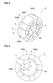
Fig. 2] Fig. 2 is a perspective view of a core body. - [
Fig. 3] Fig. 3 is a side view of the core body. - [
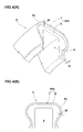
Fig. 4] Fig. 4(A) is a perspective view of a core segment showing a stepped mating surface, andFig. 4(B) is a front view of the stepped mating surface. - [
Fig. 5] Fig. 5 is a side view showing in enlarged dimension an abutted state using the stepped mating surfaces. - [
Fig. 6] Figs. 6(A) to 6(D) are schematic views, each showing a combination of the stepped mating surfaces. - [
Fig. 7] Figs. 7(A) and 7(B) are schematic views, each showing a state of an inner cavity region of the core segments presented in Table 1. - [
Fig. 8] Fig. 8 (A) is a side view of a core body, andFig. 8(B) is a perspective view of the core segment. -
- 1
- rigid core
- 2
- core body
- 2S
- tire molding surface region
- 5
- core segment
- 6
- mating surface
- 6e
- outer circumferential edge
- 7
- bordering surface region
- 8
- recessed surface region
- 9
- stepped mating surface
- b
- vulcanization mold
- t
- green tire
- An embodiment of the present invention is described in detail below.
- As shown in
Fig. 1 , arigid core 1 of the present embodiment includes anannular core body 2 provided in its outer surface with a tiremolding surface region 2S. Tire structural members, such as a carcass ply, a belt ply, a sidewall rubber, and a tread rubber, are sequentially stuck one upon another on the tiremolding surface region 2S so as to form a green tire (t) having approximately the same shape as a finished tire. The vulcanization molding is carried out by putting the green tire (t) into a vulcanization mold (b) together with therigid core 1 as usual, and then by heating and pressurizing the green tire (t) between thecore body 2 as an inner mold and the vulcanization mold (b) as an outer mold. The tiremolding surface region 2S is to be formed in approximately the same shape as an inner surface shape of the finished tire. - The
rigid core 1 includes theannular core body 2 and a circularcylindrical core 3 to be internally inserted into acenter hole 2H of theannular core body 2. Any well-known structures are properly applicable to configurations other than that of thecore body 2. Therefore, the following description is given only of thecore body 2. - The
core body 2 of the present embodiment is formed in a hollow shape having therein aninner cavity region 4 continuously extending in a circumferential di recti on. Heating means (not shown) for heating the green tire (t) from the inside, such as an electric heater, is disposed in theinner cavity region 4. - As shown in
Figs. 2 and 3 , thecore body 2 is composed of a plurality of circumferentially dividedcore segments 5. Using both circumferential end surfaces 5 of eachcore segment 5 asmating surfaces 6, the mating surfaces 6 adjacent to each other in the circumferential direction are abutted against each other and thereby theannular core body 2 is formed. - In the present embodiment, the
core segment 5 is made up of first andsecond core segments first core segment 5A, the mating surfaces 6 on both ends in the circumferential direction are inclined radially inward in a di recti on to decrease a circumferential width of the mating surfaces 6. In thesecond core segment 5B, the mating surfaces 6 on both ends in the circumferential direction are inclined radially inward in a direction to increase the circumferential width of the mating surfaces 6. This ensures that thecore segments 5 are sequentially removable radially inward from thesecond core segment 5B so as to be sequentially unloaded from a bead hole of the finished tire after the vulcanization molding. The core 3 (shown inFig. 1 ) inhibits a radially inward movement of thecore segments 5 so as to integrally couple thecore segments 5 to each other. - In the present invention, as shown in
Figs. 4(A) and 4(B) , at least one of the mating surfaces 6 and 6 adjacent to each other in the ci rcumferenti al di recti on is formed as a stepped mati ngsurface 9 comprising a borderingsurface region 7 extending along an outer circumferential edge (6e) of themating surface 6, and a recessedsurface region 8 surrounded by the borderingsurface region 7 and recessed in a step shape from the borderingsurface region 7. Thereby, the steppedmating surface 9 can contact with theadjacent mating surface 6 only in the borderingsurface region 7 as shown inFig. 5 . - Therefore, in the stepped
mating surface 9, even when the mating surfaces 6 of thecore segments 5 adjacent to each other are complicatedly deformed due to thermal expansion, the recessedsurface region 8 remains noncontacted, thus ensuring high consistency between the mating surfaces 6 and 6. Accordingly, therigid core 1 of the present invention is capable of effectively suppressing the occurrence of rubber intrusion during the vulcanization and the deterioration of roundness of the core body during the vulcanization. - For that purpose, it is preferable that the bordering
surface region 7measures 5 to 35 mm in width W from the outer circumferential edge (6e). If the width w of the borderingsurface region 7 becomes more than 35 mm, then as the contact area is wide, it becomes difficult to ensure the matching, and the effect to prevent the rubber intrusion and the lowering of the roundness is decreased. On the other hand, if the width w of the borderingsurface region 7 becomes less than 5 mm, then as the strength of the borderi ngsurface region 7 is lowered and the pressure exerted on the borderingsurface region 7 is relatively increased. Therefore, durability is decreased, and the borderingsurface region 7 undergoes deformation and damage in repeated use. - In the recessed
surface region 8, it is also preferable that the recessedsurface region 8 measures 0.05 to 1.0 mm in depth H from the borderingsurface region 7. If less than 0.05 mm, it becomes difficult to sufficiently eliminate the deformation of the mating surfaces 6 due to the thermal expansion, thus it becomes difficult to ensure the good matching. On the other hand, if more than 1.0 mm, the strength of the borderingsurface region 7 is decreased, and durability is decreased, thus the borderingsurface region 7 is liable to undergo deformation and damage in repeated use. - Although it is more preferable that the width W and the depth H of the bordering
surface region 7 are constant, both may not be constant. In such a case, it is preferable that upper limit values and lower limit values therefor fall within the above-mentioned range of 5 to 35 mm and range of 0.05 to 1.0 mm. - when the width W and the depth H of the bordering
surface region 7 fall within the above ranges, the suppression effects in the rubber intrusion and the lowering of the roundness increase with decreasing a ratio S1/S2 of an area S1 of the borderingsurface region 7 and a profile area S2 of themating surface 6. From the viewpoint of improving the suppression effects, therefore, it is preferable that the ratio S1/S2 is not more than 55%, more preferably not more than 35%. The profile area S2 means an area surrounded by a contour line (outer circumferential edge) of themating surface 6. - The stepped
mating surface 9 needs to be formed on at least one of the mating surfaces 6 and 6 adjacent to each other in the circumferential direction. Alternatively, the steppedmating surface 9 may be formed according to the following aspects (A) to (D). - (A) As shown in
Fig. 6(A) , the mating surfaces 6 and 6 of thesecond core segment 5B are respectively formed as the steppedmating surface 9, and the mating surfaces 6 and 6 of thefirst core segment 5A are respectively formed as a conventionalsmooth mating surface 10 without the recessedsurface region 8. - (B) As shown in
Fig. 6(B) , the mating surfaces 6 and 6 of thesecond core segment 5B are respectively formed as thesmooth mating surface 10, and the mating surfaces 6 and 6 of thefirst core segment 5A are respectively formed as the steppedmating surface 9. - (C) As shown in
Fig. 6(C) , only one of the mating surfaces 6 and 6 on one direction side in the circumferential direction (the right side in the present aspect) in the first andsecond core segments mating surface 9. - (D) As shown in
Fig. 6(D) , the mating surfaces 6 and 6 of the first andsecond core segments mating surface 9. - As shown in
Fig. 7(A) , theinner cavity region 4 in thecore body 2 is confined in each of thecore segments 5 so as to be formed without being communicated with themating surface 10. In this case, a heated fluid, such as steam, can be employed as heating means. The heated fluid is to flow into the individualinner cavity regions 4 so as to heat the green ti re (t) from inside with thecore body 2 interposed therebetween. - Although the particularly preferred embodiment of the present invention has been described in detail, the present invention can be modified and carried out in various embodiments without being limited to the illustrated embodiment.
- To confi rm the effects of the present invention, core bodies for forming a pneumatic tire of a tire size 195/65R15 were produced experimentally based on specifications presented in Table 1. Then, evaluations were conducted on rubber intrusion resistance and the roundness of the core bodies upon production of the pneumatic tire using each of the core bodies.
- Each of the core bodi es is made of an al umi num (coefficient of thermal expansion = 23.1 X 10⁻⁶ / degrees C), and divided into ten core segments. In a normal temperature state (20 degrees C) of the core body, a green tire is formed, and the core body is heated to a high temperature state of 150 degrees C in the vulcanization mold. Specifications other than shown in Table 1 are substantially the same, and the width w and the depth H of the bordering surface region are kept constant.
- After vulcanization molding, an amount of rubber corresponding to rubber intrusion occurred between the core segments was measured and evaluated by a 10-point method. That is, a large value indicates less rubber intrusion, resulting in excellent rubber intrusion resistance. The evaluation of the rubber intrusion resistance was conducted in the first, 300th, 600th, and 1000th vulcanization molding in order to also evaluate a change in the rubber intrusion resistance with increasing the number of the vulcanization molding.
- The core body was slowly rotated around an axis thereof so as to measure variations in i rregul ari ti es on the outer circumferential surface of the core body at an equatorial position by using a dial gauge, and a measurement result was evaluated by the 10-point method. That is, a large value indicates less variations in the irregularities, resulting in excellent accuracy of roundness. The roundness was measu red in the fi rst, 300th, 600th, and 1000th vulcanization mol di ng in order to also evaluate a change in roundness with increasing the number of the vulcanization molding. For example, the 600th roundness denotes the roundness of the core body measured when, upon termination of the 600th vulcanization, the segments were unloaded from the tire and the rigid core was reassembled at normal temperature.


- As presented in Table 1, it can be confirmed that the rigid cores of Examples employing the stepped mating surfaces as the mating surfaces are capable of enhancing the consistency between the core segments so as to improve the rubber intrusion resistance and the roundness.
- It is confirmable that, as the width W was smal in Example 4 and the depth H was large in Example 12, the strength of their bordering surface regions became insufficient, and the bordering surface regions were deformed during repeated use, and thereby the degree of deterioration in the resistance to intrusion of rubber and the degree of lowering of the roundness became high.
Claims (3)
- A rigid core for forming a tire which comprises an annular core body provided in its outer surface with a tire molding surface region for forming a green tire and which is for subject the green tire to vulcanization molding between a vulcanization mold and the core body by being put into the vulcanization mold together with the green tire, characterized in that
the core body comprises a plurality of circumferentially divided core segments,
both circumferential end surfaces of each of the core segments are used as mating surfaces, and the mating surfaces adjacent to each other in the ci rcumferenti al di recti on are abutted against each other to form the core body, and
at least one of the mating surfaces adjacent to each other in the ci rcumferenti al di recti on is formed as a stepped mati ng surface comprising a bordering surface region extending along an outer circumferential edge of the mating surface, and a recessed surface region surrounded by the bordering surface region and recessed in a step shape from the bordering surface region so that only the bordering surface region contacts with the adjacent mating surface. - The rigid core for forming a tire according to claim 1, which is characterized in that the bordering surface region measures 5 to 35 mm in width W from the outer circumferential edge.
- The rigid core for forming a tire according to claim 1 or 2, which is characterized in that the recessed surface region measures 0.05 to 1.0 mm in depth H from the bordering surface region.
Applications Claiming Priority (2)
| Application Number | Priority Date | Filing Date | Title |
|---|---|---|---|
| JP2012050744A JP5486622B2 (en) | 2012-03-07 | 2012-03-07 | Rigid core for tire formation |
| PCT/JP2013/050546 WO2013132884A1 (en) | 2012-03-07 | 2013-01-15 | Rigid core for forming tire |
Publications (3)
| Publication Number | Publication Date |
|---|---|
| EP2823955A1 true EP2823955A1 (en) | 2015-01-14 |
| EP2823955A4 EP2823955A4 (en) | 2016-01-27 |
| EP2823955B1 EP2823955B1 (en) | 2017-05-10 |
Family
ID=49116371
Family Applications (1)
| Application Number | Title | Priority Date | Filing Date |
|---|---|---|---|
| EP13758042.9A Not-in-force EP2823955B1 (en) | 2012-03-07 | 2013-01-15 | Rigid core for forming a tire |
Country Status (5)
| Country | Link |
|---|---|
| US (1) | US9039399B2 (en) |
| EP (1) | EP2823955B1 (en) |
| JP (1) | JP5486622B2 (en) |
| CN (1) | CN104136205B (en) |
| WO (1) | WO2013132884A1 (en) |
Families Citing this family (3)
| Publication number | Priority date | Publication date | Assignee | Title |
|---|---|---|---|---|
| JP6242146B2 (en) | 2013-10-10 | 2017-12-06 | 住友ゴム工業株式会社 | Rigid core for forming tire, and tire manufacturing method using the same |
| JP6212413B2 (en) * | 2014-03-07 | 2017-10-11 | 住友ゴム工業株式会社 | Rigid core for tire formation |
| JP6463102B2 (en) * | 2014-12-01 | 2019-01-30 | 住友ゴム工業株式会社 | Rigid core for tire formation |
Family Cites Families (17)
| Publication number | Priority date | Publication date | Assignee | Title |
|---|---|---|---|---|
| US1343504A (en) * | 1920-06-15 | Collapsible core | ||
| US1735896A (en) * | 1929-11-19 | Collapsible cobs structure | ||
| US1366750A (en) * | 1920-04-08 | 1921-01-25 | Smith Fred | Tire-casing core |
| US1784960A (en) * | 1925-06-12 | 1930-12-16 | Nat Rubber Machinery Co | Collapsible core |
| JP2003340824A (en) * | 2002-05-27 | 2003-12-02 | Bridgestone Corp | Tire vulcanization molding method and tire molding die |
| JP4373160B2 (en) * | 2003-08-21 | 2009-11-25 | 株式会社ブリヂストン | Tire manufacturing core |
| DE60323547D1 (en) * | 2003-11-28 | 2008-10-23 | Pirelli | METHOD FOR PRODUCING AIR TIRES AND TORUM CORE FOR IMPLEMENTING THE PROCESS. |
| JP2006117115A (en) * | 2004-10-21 | 2006-05-11 | Toyota Motor Corp | Pneumatic tire |
| US20070023967A1 (en) | 2005-06-17 | 2007-02-01 | Michelin Recherche Et Technique S.A. | Device and process for cooling a core |
| FR2887176B1 (en) * | 2005-06-17 | 2009-07-17 | Michelin Soc Tech | DEVICE AND METHOD FOR COOLING A CORE |
| US7621308B2 (en) * | 2005-12-02 | 2009-11-24 | The Goodyear Tire & Rubber Company | Tire building core latching and transport mechanism |
| JP5406701B2 (en) * | 2009-12-25 | 2014-02-05 | 住友ゴム工業株式会社 | Rigid core for tire vulcanization |
| JP5113861B2 (en) * | 2010-02-15 | 2013-01-09 | 住友ゴム工業株式会社 | Pneumatic tire manufacturing method and rigid core used therefor |
| JP5438545B2 (en) | 2010-02-19 | 2014-03-12 | 住友ゴム工業株式会社 | Pneumatic tire manufacturing method |
| JP5444385B2 (en) * | 2012-01-18 | 2014-03-19 | 住友ゴム工業株式会社 | Rigid core for tire formation |
| JP5698694B2 (en) * | 2012-03-19 | 2015-04-08 | 住友ゴム工業株式会社 | Rigid core for tire formation |
| JP5667606B2 (en) * | 2012-07-30 | 2015-02-12 | 住友ゴム工業株式会社 | Rigid core for tire formation |
-
2012
- 2012-03-07 JP JP2012050744A patent/JP5486622B2/en not_active Expired - Fee Related
-
2013
- 2013-01-15 CN CN201380010452.1A patent/CN104136205B/en not_active Expired - Fee Related
- 2013-01-15 US US14/379,142 patent/US9039399B2/en active Active
- 2013-01-15 WO PCT/JP2013/050546 patent/WO2013132884A1/en not_active Ceased
- 2013-01-15 EP EP13758042.9A patent/EP2823955B1/en not_active Not-in-force
Also Published As
| Publication number | Publication date |
|---|---|
| EP2823955A4 (en) | 2016-01-27 |
| JP2013184368A (en) | 2013-09-19 |
| JP5486622B2 (en) | 2014-05-07 |
| US20150030711A1 (en) | 2015-01-29 |
| CN104136205A (en) | 2014-11-05 |
| US9039399B2 (en) | 2015-05-26 |
| CN104136205B (en) | 2016-05-11 |
| WO2013132884A1 (en) | 2013-09-12 |
| EP2823955B1 (en) | 2017-05-10 |
Similar Documents
| Publication | Publication Date | Title |
|---|---|---|
| JP5444385B2 (en) | Rigid core for tire formation | |
| JP6085940B2 (en) | Rehabilitation tire | |
| JP5480922B2 (en) | Pneumatic tire and manufacturing method thereof | |
| EP2818291B1 (en) | Rigid core for forming tire | |
| EP2823955B1 (en) | Rigid core for forming a tire | |
| JP5667433B2 (en) | Tire vulcanization mold and method for manufacturing pneumatic tire | |
| JP2012236301A (en) | Mold for molding tire and method of manufacturing tire | |
| US9144947B2 (en) | Rigid core for forming tire | |
| EP3115167B1 (en) | Rigid core for tire formation and tire production method using the same | |
| JP4716282B2 (en) | Tire mold and tire manufacturing method | |
| JP6454082B2 (en) | Rigid core for forming tire and method of manufacturing tire using the same | |
| CN104185541B (en) | For forming the rigid core for building of tire | |
| JP2006240503A (en) | Pneumatic tire for motorcycle | |
| JP2024118688A (en) | Pneumatic tires and vulcanization molds | |
| CN106457898A (en) | Pneumatic tires and molds for tire vulcanization | |
| JP4800841B2 (en) | Tire mold and tire manufacturing method | |
| JP6085939B2 (en) | Rehabilitation tire | |
| JP2007015278A (en) | Tire bladder and tire manufacturing method | |
| JP2012101389A (en) | Tire vulcanizing bladder |
Legal Events
| Date | Code | Title | Description |
|---|---|---|---|
| PUAI | Public reference made under article 153(3) epc to a published international application that has entered the european phase |
Free format text: ORIGINAL CODE: 0009012 |
|
| 17P | Request for examination filed |
Effective date: 20140917 |
|
| AK | Designated contracting states |
Kind code of ref document: A1 Designated state(s): AL AT BE BG CH CY CZ DE DK EE ES FI FR GB GR HR HU IE IS IT LI LT LU LV MC MK MT NL NO PL PT RO RS SE SI SK SM TR |
|
| AX | Request for extension of the european patent |
Extension state: BA ME |
|
| DAX | Request for extension of the european patent (deleted) | ||
| REG | Reference to a national code |
Ref country code: DE Ref legal event code: R079 Ref document number: 602013020980 Country of ref document: DE Free format text: PREVIOUS MAIN CLASS: B29D0030120000 Ipc: B29D0030060000 |
|
| RA4 | Supplementary search report drawn up and despatched (corrected) |
Effective date: 20160105 |
|
| RIC1 | Information provided on ipc code assigned before grant |
Ipc: B29D 30/12 20060101ALI20151221BHEP Ipc: B29D 30/06 20060101AFI20151221BHEP |
|
| GRAP | Despatch of communication of intention to grant a patent |
Free format text: ORIGINAL CODE: EPIDOSNIGR1 |
|
| STAA | Information on the status of an ep patent application or granted ep patent |
Free format text: STATUS: GRANT OF PATENT IS INTENDED |
|
| INTG | Intention to grant announced |
Effective date: 20170222 |
|
| GRAS | Grant fee paid |
Free format text: ORIGINAL CODE: EPIDOSNIGR3 |
|
| GRAA | (expected) grant |
Free format text: ORIGINAL CODE: 0009210 |
|
| STAA | Information on the status of an ep patent application or granted ep patent |
Free format text: STATUS: THE PATENT HAS BEEN GRANTED |
|
| AK | Designated contracting states |
Kind code of ref document: B1 Designated state(s): AL AT BE BG CH CY CZ DE DK EE ES FI FR GB GR HR HU IE IS IT LI LT LU LV MC MK MT NL NO PL PT RO RS SE SI SK SM TR |
|
| REG | Reference to a national code |
Ref country code: GB Ref legal event code: FG4D |
|
| REG | Reference to a national code |
Ref country code: AT Ref legal event code: REF Ref document number: 891849 Country of ref document: AT Kind code of ref document: T Effective date: 20170515 Ref country code: CH Ref legal event code: EP |
|
| REG | Reference to a national code |
Ref country code: IE Ref legal event code: FG4D |
|
| REG | Reference to a national code |
Ref country code: DE Ref legal event code: R096 Ref document number: 602013020980 Country of ref document: DE |
|
| REG | Reference to a national code |
Ref country code: NL Ref legal event code: MP Effective date: 20170510 |
|
| REG | Reference to a national code |
Ref country code: LT Ref legal event code: MG4D |
|
| REG | Reference to a national code |
Ref country code: AT Ref legal event code: MK05 Ref document number: 891849 Country of ref document: AT Kind code of ref document: T Effective date: 20170510 |
|
| PG25 | Lapsed in a contracting state [announced via postgrant information from national office to epo] |
Ref country code: AT Free format text: LAPSE BECAUSE OF FAILURE TO SUBMIT A TRANSLATION OF THE DESCRIPTION OR TO PAY THE FEE WITHIN THE PRESCRIBED TIME-LIMIT Effective date: 20170510 Ref country code: NO Free format text: LAPSE BECAUSE OF FAILURE TO SUBMIT A TRANSLATION OF THE DESCRIPTION OR TO PAY THE FEE WITHIN THE PRESCRIBED TIME-LIMIT Effective date: 20170810 Ref country code: ES Free format text: LAPSE BECAUSE OF FAILURE TO SUBMIT A TRANSLATION OF THE DESCRIPTION OR TO PAY THE FEE WITHIN THE PRESCRIBED TIME-LIMIT Effective date: 20170510 Ref country code: HR Free format text: LAPSE BECAUSE OF FAILURE TO SUBMIT A TRANSLATION OF THE DESCRIPTION OR TO PAY THE FEE WITHIN THE PRESCRIBED TIME-LIMIT Effective date: 20170510 Ref country code: GR Free format text: LAPSE BECAUSE OF FAILURE TO SUBMIT A TRANSLATION OF THE DESCRIPTION OR TO PAY THE FEE WITHIN THE PRESCRIBED TIME-LIMIT Effective date: 20170811 Ref country code: LT Free format text: LAPSE BECAUSE OF FAILURE TO SUBMIT A TRANSLATION OF THE DESCRIPTION OR TO PAY THE FEE WITHIN THE PRESCRIBED TIME-LIMIT Effective date: 20170510 Ref country code: FI Free format text: LAPSE BECAUSE OF FAILURE TO SUBMIT A TRANSLATION OF THE DESCRIPTION OR TO PAY THE FEE WITHIN THE PRESCRIBED TIME-LIMIT Effective date: 20170510 |
|
| PG25 | Lapsed in a contracting state [announced via postgrant information from national office to epo] |
Ref country code: RS Free format text: LAPSE BECAUSE OF FAILURE TO SUBMIT A TRANSLATION OF THE DESCRIPTION OR TO PAY THE FEE WITHIN THE PRESCRIBED TIME-LIMIT Effective date: 20170510 Ref country code: BG Free format text: LAPSE BECAUSE OF FAILURE TO SUBMIT A TRANSLATION OF THE DESCRIPTION OR TO PAY THE FEE WITHIN THE PRESCRIBED TIME-LIMIT Effective date: 20170810 Ref country code: LV Free format text: LAPSE BECAUSE OF FAILURE TO SUBMIT A TRANSLATION OF THE DESCRIPTION OR TO PAY THE FEE WITHIN THE PRESCRIBED TIME-LIMIT Effective date: 20170510 Ref country code: NL Free format text: LAPSE BECAUSE OF FAILURE TO SUBMIT A TRANSLATION OF THE DESCRIPTION OR TO PAY THE FEE WITHIN THE PRESCRIBED TIME-LIMIT Effective date: 20170510 Ref country code: PL Free format text: LAPSE BECAUSE OF FAILURE TO SUBMIT A TRANSLATION OF THE DESCRIPTION OR TO PAY THE FEE WITHIN THE PRESCRIBED TIME-LIMIT Effective date: 20170510 Ref country code: SE Free format text: LAPSE BECAUSE OF FAILURE TO SUBMIT A TRANSLATION OF THE DESCRIPTION OR TO PAY THE FEE WITHIN THE PRESCRIBED TIME-LIMIT Effective date: 20170510 Ref country code: IS Free format text: LAPSE BECAUSE OF FAILURE TO SUBMIT A TRANSLATION OF THE DESCRIPTION OR TO PAY THE FEE WITHIN THE PRESCRIBED TIME-LIMIT Effective date: 20170910 |
|
| REG | Reference to a national code |
Ref country code: FR Ref legal event code: PLFP Year of fee payment: 6 |
|
| PG25 | Lapsed in a contracting state [announced via postgrant information from national office to epo] |
Ref country code: RO Free format text: LAPSE BECAUSE OF FAILURE TO SUBMIT A TRANSLATION OF THE DESCRIPTION OR TO PAY THE FEE WITHIN THE PRESCRIBED TIME-LIMIT Effective date: 20170510 Ref country code: CZ Free format text: LAPSE BECAUSE OF FAILURE TO SUBMIT A TRANSLATION OF THE DESCRIPTION OR TO PAY THE FEE WITHIN THE PRESCRIBED TIME-LIMIT Effective date: 20170510 Ref country code: SK Free format text: LAPSE BECAUSE OF FAILURE TO SUBMIT A TRANSLATION OF THE DESCRIPTION OR TO PAY THE FEE WITHIN THE PRESCRIBED TIME-LIMIT Effective date: 20170510 Ref country code: DK Free format text: LAPSE BECAUSE OF FAILURE TO SUBMIT A TRANSLATION OF THE DESCRIPTION OR TO PAY THE FEE WITHIN THE PRESCRIBED TIME-LIMIT Effective date: 20170510 Ref country code: EE Free format text: LAPSE BECAUSE OF FAILURE TO SUBMIT A TRANSLATION OF THE DESCRIPTION OR TO PAY THE FEE WITHIN THE PRESCRIBED TIME-LIMIT Effective date: 20170510 |
|
| REG | Reference to a national code |
Ref country code: DE Ref legal event code: R097 Ref document number: 602013020980 Country of ref document: DE |
|
| PG25 | Lapsed in a contracting state [announced via postgrant information from national office to epo] |
Ref country code: SM Free format text: LAPSE BECAUSE OF FAILURE TO SUBMIT A TRANSLATION OF THE DESCRIPTION OR TO PAY THE FEE WITHIN THE PRESCRIBED TIME-LIMIT Effective date: 20170510 Ref country code: IT Free format text: LAPSE BECAUSE OF FAILURE TO SUBMIT A TRANSLATION OF THE DESCRIPTION OR TO PAY THE FEE WITHIN THE PRESCRIBED TIME-LIMIT Effective date: 20170510 |
|
| PLBE | No opposition filed within time limit |
Free format text: ORIGINAL CODE: 0009261 |
|
| STAA | Information on the status of an ep patent application or granted ep patent |
Free format text: STATUS: NO OPPOSITION FILED WITHIN TIME LIMIT |
|
| 26N | No opposition filed |
Effective date: 20180213 |
|
| PG25 | Lapsed in a contracting state [announced via postgrant information from national office to epo] |
Ref country code: SI Free format text: LAPSE BECAUSE OF FAILURE TO SUBMIT A TRANSLATION OF THE DESCRIPTION OR TO PAY THE FEE WITHIN THE PRESCRIBED TIME-LIMIT Effective date: 20170510 |
|
| REG | Reference to a national code |
Ref country code: CH Ref legal event code: PL |
|
| GBPC | Gb: european patent ceased through non-payment of renewal fee |
Effective date: 20180115 |
|
| PG25 | Lapsed in a contracting state [announced via postgrant information from national office to epo] |
Ref country code: LU Free format text: LAPSE BECAUSE OF NON-PAYMENT OF DUE FEES Effective date: 20180115 |
|
| REG | Reference to a national code |
Ref country code: IE Ref legal event code: MM4A |
|
| REG | Reference to a national code |
Ref country code: BE Ref legal event code: MM Effective date: 20180131 |
|
| PG25 | Lapsed in a contracting state [announced via postgrant information from national office to epo] |
Ref country code: BE Free format text: LAPSE BECAUSE OF NON-PAYMENT OF DUE FEES Effective date: 20180131 Ref country code: GB Free format text: LAPSE BECAUSE OF NON-PAYMENT OF DUE FEES Effective date: 20180115 Ref country code: CH Free format text: LAPSE BECAUSE OF NON-PAYMENT OF DUE FEES Effective date: 20180131 Ref country code: LI Free format text: LAPSE BECAUSE OF NON-PAYMENT OF DUE FEES Effective date: 20180131 |
|
| PG25 | Lapsed in a contracting state [announced via postgrant information from national office to epo] |
Ref country code: IE Free format text: LAPSE BECAUSE OF NON-PAYMENT OF DUE FEES Effective date: 20180115 |
|
| PG25 | Lapsed in a contracting state [announced via postgrant information from national office to epo] |
Ref country code: MC Free format text: LAPSE BECAUSE OF FAILURE TO SUBMIT A TRANSLATION OF THE DESCRIPTION OR TO PAY THE FEE WITHIN THE PRESCRIBED TIME-LIMIT Effective date: 20170510 |
|
| PG25 | Lapsed in a contracting state [announced via postgrant information from national office to epo] |
Ref country code: MT Free format text: LAPSE BECAUSE OF NON-PAYMENT OF DUE FEES Effective date: 20180115 |
|
| PG25 | Lapsed in a contracting state [announced via postgrant information from national office to epo] |
Ref country code: TR Free format text: LAPSE BECAUSE OF FAILURE TO SUBMIT A TRANSLATION OF THE DESCRIPTION OR TO PAY THE FEE WITHIN THE PRESCRIBED TIME-LIMIT Effective date: 20170510 |
|
| PG25 | Lapsed in a contracting state [announced via postgrant information from national office to epo] |
Ref country code: HU Free format text: LAPSE BECAUSE OF FAILURE TO SUBMIT A TRANSLATION OF THE DESCRIPTION OR TO PAY THE FEE WITHIN THE PRESCRIBED TIME-LIMIT; INVALID AB INITIO Effective date: 20130115 Ref country code: PT Free format text: LAPSE BECAUSE OF FAILURE TO SUBMIT A TRANSLATION OF THE DESCRIPTION OR TO PAY THE FEE WITHIN THE PRESCRIBED TIME-LIMIT Effective date: 20170510 |
|
| PG25 | Lapsed in a contracting state [announced via postgrant information from national office to epo] |
Ref country code: MK Free format text: LAPSE BECAUSE OF NON-PAYMENT OF DUE FEES Effective date: 20170510 Ref country code: CY Free format text: LAPSE BECAUSE OF FAILURE TO SUBMIT A TRANSLATION OF THE DESCRIPTION OR TO PAY THE FEE WITHIN THE PRESCRIBED TIME-LIMIT Effective date: 20170510 |
|
| PG25 | Lapsed in a contracting state [announced via postgrant information from national office to epo] |
Ref country code: AL Free format text: LAPSE BECAUSE OF FAILURE TO SUBMIT A TRANSLATION OF THE DESCRIPTION OR TO PAY THE FEE WITHIN THE PRESCRIBED TIME-LIMIT Effective date: 20170510 |
|
| P01 | Opt-out of the competence of the unified patent court (upc) registered |
Effective date: 20230510 |
|
| PGFP | Annual fee paid to national office [announced via postgrant information from national office to epo] |
Ref country code: FR Payment date: 20231212 Year of fee payment: 12 |
|
| PGFP | Annual fee paid to national office [announced via postgrant information from national office to epo] |
Ref country code: DE Payment date: 20231128 Year of fee payment: 12 |
|
| REG | Reference to a national code |
Ref country code: DE Ref legal event code: R119 Ref document number: 602013020980 Country of ref document: DE |
|
| PG25 | Lapsed in a contracting state [announced via postgrant information from national office to epo] |
Ref country code: DE Free format text: LAPSE BECAUSE OF NON-PAYMENT OF DUE FEES Effective date: 20250801 |
|
| PG25 | Lapsed in a contracting state [announced via postgrant information from national office to epo] |
Ref country code: FR Free format text: LAPSE BECAUSE OF NON-PAYMENT OF DUE FEES Effective date: 20250131 |