EP2823941A1 - Cartouches de rasoir - Google Patents
Cartouches de rasoir Download PDFInfo
- Publication number
- EP2823941A1 EP2823941A1 EP13175866.6A EP13175866A EP2823941A1 EP 2823941 A1 EP2823941 A1 EP 2823941A1 EP 13175866 A EP13175866 A EP 13175866A EP 2823941 A1 EP2823941 A1 EP 2823941A1
- Authority
- EP
- European Patent Office
- Prior art keywords
- blade
- protrusions
- blades
- cartridge
- support
- Prior art date
- Legal status (The legal status is an assumption and is not a legal conclusion. Google has not performed a legal analysis and makes no representation as to the accuracy of the status listed.)
- Withdrawn
Links
Images


Classifications
-
- B—PERFORMING OPERATIONS; TRANSPORTING
- B26—HAND CUTTING TOOLS; CUTTING; SEVERING
- B26B—HAND-HELD CUTTING TOOLS NOT OTHERWISE PROVIDED FOR
- B26B21/00—Razors of the open or knife type; Safety razors or other shaving implements of the planing type; Hair-trimming devices involving a razor-blade; Equipment therefor
- B26B21/08—Razors of the open or knife type; Safety razors or other shaving implements of the planing type; Hair-trimming devices involving a razor-blade; Equipment therefor involving changeable blades
- B26B21/14—Safety razors with one or more blades arranged transversely to the handle
- B26B21/22—Safety razors with one or more blades arranged transversely to the handle involving several blades to be used simultaneously
- B26B21/222—Safety razors with one or more blades arranged transversely to the handle involving several blades to be used simultaneously with the blades moulded into, or attached to, a changeable unit
- B26B21/227—Safety razors with one or more blades arranged transversely to the handle involving several blades to be used simultaneously with the blades moulded into, or attached to, a changeable unit with blades being resiliently mounted in the changeable unit
-
- B—PERFORMING OPERATIONS; TRANSPORTING
- B26—HAND CUTTING TOOLS; CUTTING; SEVERING
- B26B—HAND-HELD CUTTING TOOLS NOT OTHERWISE PROVIDED FOR
- B26B21/00—Razors of the open or knife type; Safety razors or other shaving implements of the planing type; Hair-trimming devices involving a razor-blade; Equipment therefor
- B26B21/40—Details or accessories
- B26B21/4012—Housing details, e.g. for cartridges
Definitions
- the present invention relates to razor cartridges.
- blade and blade support are formed of a single piece of material. Without the requirement of welding the blade to a blade support, the manufacturing process is made much simpler.
- single-piece blades are typically thinner than conventional blade assemblies where the blade is welded to a blade support, leading to other problems with stability of the blades. Specifically, thinner blades are more prone to flexing during use, which can lead to an increased risk of skin irritation caused by nicks and cuts during shaving.
- a razor cartridge comprising a housing comprising a front and a rear, at least one blade disposed within the housing, the blade comprising a cutting portion having a cutting edge directed towards the front of the housing; and a supporting portion positioned at an angle ⁇ relative to the cutting portion, wherein the supporting portion and cutting portion are formed out of a single sheet of material; and at least two supports spaced apart from one another, each support extending from one of the front or rear of the housing in a direction towards the other of the front or rear of the housing, the supports each comprising a base, and at least one protrusion extending from the base, wherein said at least one protrusion of each support is configured to contact the supporting portion of said at least one blade.
- the effort required to manufacture a razor cartridge is reduced, and the amount of material used to manufacture the cartridge is also reduced - thereby resulting in a much cheaper manufacturing process overall.
- the blades are more prone to flexing when under force (i.e. during shaving) resulting in "chatter" (front-to-back movement of the blade when in use).
- at least two contact points are provided between the supporting portion of the blade and the supports across the length of each blade.
- the razor cartridge comprises at least two blades, each having a cutting edge directed towards a front of the razor cartridge, wherein there is a blade span of less than 1.0 mm between at least two adjacent cutting edges.
- blades of the present invention are better supported by having multiple contact points with a support extending from the housing and by using blades formed of a single piece of material (i.e. not having a separate blade and blade support), the amount of material between adjacent blades is reduced allowing for better wash-through when the razor cartridge is in use.
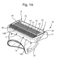
- FIG. 1A shows a razor blade cartridge or unit 10 intended for fixing to a razor handle (not shown).
- the razor blade cartridge 10 is intended to be permanently fixed to the handle, for example, where the razor is a disposable razor.
- the razor blade cartridge 10 may be removably attached to the handle by a connecting member 35 such that the cartridge alone may be replaced and disposed of when necessary.
- razor cartridge 10 includes housing 12, guard 14 at the front of housing 12, cap 2 at the rear of the housing 12 and five blades 18, 20, 22, 23, and 25 disposed between the guard 14 and the cap 2.
- Primary blade 18 is nearest the guard
- second blade 20 is next nearest the guard, and so on until the fifth blade 25 that is furthest from the guard.
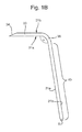
- each blade is formed of a cutting portion 30 having a cutting edge 34 at one end, and a supporting portion 40, extending at an angle ⁇ from the other end of the cutting portion 30.
- the cutting portion 30 and supporting portion 40 are formed of a single piece of material, forming a "bent blade". This is in contrast to razor cartridges currently found on the market, such as the Gillette ® Fusion ® , where a much smaller flat blade with cutting edge is welded to a bent blade support formed of a separate piece of material.
- each blade has a cutting edge 34 and a tip 36.
- Each blade further has a front and back side 31a and 31b respectively.
- the thickness T of a blade is determined by the distance between the front and back sides of the blade and typically is between 0.07 and 0.12mm.
- thinner blades are more prone to vibration/movement during use resulting in "chatter" between adjacent blades or between a blade and the guard or cap.
- This increase in movement and vibration of the blades can lead to discomfort to the user and it can negate the previously mentioned wash-through benefits since, during use, there will be times when the blades are closer together.
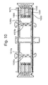
- At least two supports 72 are provided, extending from either the front or rear of the housing. It will be appreciated that although three supports 72 are shown, there may be two, four or more supports 72 provided in the cartridge.
- the supports 72 are spaced apart from one another, preferably at regular intervals across the width of the cartridge, to provide even support and regular touch points for the respective blades. By spacing the supports 72 apart from one another, gaps 73 are still provided between them through which water can flow when the cartridge is rinsed.
- the supports 72 have a base 75 and a plurality of protrusions 74 extending from the base 72. In a preferred embodiment, the number of protrusions corresponds to the number of blades held within the razor cartridge.
- protrusions there may be more protrusions than blades. In a preferred embodiment, there are two more protrusions than the number of blades being held. In an alternative embodiment, there may be fewer protrusions than blades, in which case not all the blades are supported by the support. For example, in a particular embodiment of a razor cartridge having three blades, protrusions may be provided to support the second and third blade but not the first.
- each protrusion When the cartridge is assembled, each protrusion will contact the front 31a or back 31b side of the supporting portion 40 of at least one blade.
- six protrusions 74 are provided in a cartridge intended to carry five blades (as shown in FIG. 2A ). At least four of the protrusions 74 are intended to make contact with the front or back side of the supporting portion of at least one blade when the blades are in an at rest position.
- Two additional end protrusions 76c are provided. These end protrusions 76c do not necessarily make contact with the supporting portion of a blade when in a rest position.
- FIGS. 3 and 3A When a user shaves with the razor cartridges, the blades may be deflected from their original rest positions abutting a particular protrusion and may be pushed back within the cartridge until they abut an adjacent protrusion. For example, FIG.
- FIG. 3 shows a blade in a rest position, where a rear side of the supporting portion is in contact with one protrusion.
- FIG. 3A shows the same blade in a deflected position while in use and it can be seen that if it were deflected further, a front side of the supporting portion would come into contact with an adjacent protrusion, preventing further motion in that direction.
- a single protrusion may provide support to two blades when in use.
- the protrusions 74 can be positioned such that, in a rest position, one protrusion makes contact with the front side of the supporting portion of a blade and another protrusion makes contact with the back side of the supporting portion of the same blade. In this embodiment, there is little to no room for the blade to move when being used to shave.
- the protrusions 74 are positioned in a single row along the length of the base of the support.
- two rows 78A and 78B of protrusions are provided that are off-set from one another such that adjacent protrusions in one row contact alternative blades.
- This embodiment with multiple rows off-set from one another is particularly preferable in the embodiment where two protrusions contact respectively the front and back sides of the supporting portion of a single blade.
- providing contact sides at both the front and back of the supporting portion further reduces chatter of blades in the cartridge.
- Off-setting adjacent protrusions makes it easier to manufacture, particularly when the support is moulded. In this respect, the distance between adjacent protrusions is significantly greater where the rows of protrusions are off-set from one another, even though the gap within which a blade can sit remains the same.
- the distance between adjacent protrusions 74 compared to the thickness T of the supporting portion (i.e. the distance from the front side 31a to the back side 31b of the blade) of respective blades determines the amount of flex and freedom to move a blade has when in use.
- the distance 76 between adjacent protrusions may be between 0.08mm to 0.18mm, preferably 0.08mm to 0.11mm.
- protrusions that contact adjacent blades are referred to as adjacent protrusions - they need not be in the same row.
- the distance between adjacent protrusions is the same as the thickness T of the supporting portion of a blade, there will be little to no room for movement of the blade in the direction of travel of the cartridge when in use.
- increasing the distance 76 compared to the thickness T of the blade support provides more room for the blades to flex when in use.
- the protrusions 74 can be any shape size sufficient to provide support to the blades.
- respective protrusions may have widths w p of, for example, between 0.1, 0.5, 1, 1.5, 2 to 2.5, 3, 3.5 to 5mm.
- the protrusions may have depths d p of between 1, 1.5, 2 to 2.5, 3, 3.5 to 4mm.
- the protrusions may have straight and parallel sides.
- the protrusions may be conical or formed in the shape of a pyramid where they are wider at the point of contact with the base than at the top of the protrusion.
- the gap between adjacent protrusions may be equivalent to the thickness of the supporting portion of a blade being held at the point of contact with the base, ensuring that the blade remains firmly in place, while the angular slope of the protrusion as it extends away from the base can be optimsed to allow a certain degree of movement of the blade during use.
- the protrusions may be narrower at the base than at the point furthest from the base.
- each protrusion 74 is cylindrical or oblong, as shown in FIG. 4 such that the supporting portion of a blade extends along a tangent 39 of the tip 37 of the protrusion 74.
- rounded protrusions are generally less complicated to mold, manufacture and assemble than other shapes.
- each protrusion has the same profile.
- different protrusions within the razor cartridge have different shapes and profiles depending on the particular control required from that protrusion. It will be appreciated that any other shape of protrusion or combination of shapes could be used to obtain the desired contact at the intersection of the protrusion and blade.
- protrusions 74 in base member 72 may be laid out in several different ways as described below.
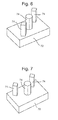
- FIG. 8 rather than a slalom-like arrangement, a linear column of protrusions 74 is shown.
- FIG. 9 a layout of two linear columns of protrusions 74 are shown in accordance the present invention.
- FIG. 2 illustrates an embodiment of the support that extends from the front of the cartridge housing to the rear of the cartridge housing.
- the support may extend only part-way across the housing, provided it still has sufficient protrusions extending therefrom that are configured to contact the supporting portion of blades disposed within the cartridge.
- FIG. 2 Three supports are shown in FIG. 2 . However, it will be appreciated that the number of supports may be varied depending on the width of the cartridge. For example, in a smaller cartridge, fewer supports may be required and conversely, in a wider cartridge, more supports may be required. In an embodiment, adjacent supports are spaced apart by between 0.4mm, 1.0mm or 2.0mm to 2.5mm, 3.5mm or 5.0mem.
- the cartridge housing has side walls 80, 82 disposed at either end of the cartridge extending between the front and rear of the housing. Slots 84 are provided within these side walls within which the blades may be disposed.
- spring fingers 86 extend from the side walls 80, 82 upon which the blades may rest. In use, as the blades are deflected, the spring fingers 86 serve to bias the blades back into their original positions.
- the supports are positioned away from the spring fingers and the side walls of the housing.
- each support is positioned a distance of at least 3mm, 3.5mm or 4mm to a third of a length of the blade away from the side walls.
- the supports may be positioned such that each blade has a contact point at either end of the blade (by the slots) and at regular intervals along the length of the blade (by the support).
- each support has a corresponding number of protrusions and the members are positioned such that the protrusions are aligned. Thus a blade would be contacted and supported by a protrusion on each of the supports.
- One or more supports may be formed of the same material as the housing.
- the supports and the housing are formed as a single unit, thus adding stability to the housing of the cartridge.
- the housing and supports are formed of plastic, such as polystyrene, ABS, polypropylene, polyamides, polyphenylenes, Noryl ® (a polyphenylene oxide-styrene blend), or Noryl GTX ® (a blend of polyamids (PA) or polyphenylene ether polymer (PPE)).
- the base members 72 can be either flexible or rigid, and can be fitted as a separate part or integrally molded as part of the cartridge housing 12.
- the protrusions 74 can be configured as flexible or rigid, but may be desirably rigid, and made from any kind of material, such as elastomeric, plastic or metal. If non-rigid protrusions are desired, materials such as polyethylenes, thermoplastics, elastomers, or rubbers may be utilized. With rigid protrusions, plastics such as polystyrene, ABS, rigid polyvinylchloride (PVC), polyamides, polyphenylenes, Noryl® (a polyphenylene oxide-styrene blend), or Noryl GTX® (a blend of polyamide (PA) or polyphenylene ether polymer (PPE)) may be utilized. Either one, or both of the base member and protrusion may be designed to be resilient but flexible in order to absorb forces effectively.
- PVC polyvinylchloride
- PA polyamide
- PPE polyphenylene ether polymer
- FIG. 1B shows an exemplary blade, having a cutting portion (30) angled relative to the supporting portion (40).
- the angle ⁇ between the cutting portion (30) and supporting portion (40) may be between 60°, 65° or 70° and 75°, 80° or 88°.
- the blades are positioned typically having the blade edge directed towards the front of the cartridge.
- a guard 14 is provided at the front of the cartridge and a cap 2 is provided at the rear of the cartridge.
- the respective positioning of the guard and cap may be reversed or the guard may be formed separately to the housing and mounted directly to the razor handle.
- the guard and cap respectively provide a first skin contact point at the front of the cartridge and a second skin contact point at a rear of the cartridge.
- a skin contact plane P s is defined tangential to the guard and cap. As shown in the drawings of this application, the blades typically lie below the skin contact plane, though in some cases, the tip of the blade may lie in or above the skin contact plane.
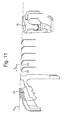
- a span ⁇ s is defined as the distance between adjacent blade edges, as shown in FIG. 11 . Further spans ⁇ are defined between the guard and first blade of the cartridge and the final blade in the cartridge and the cap.
- the span between adjacent blade edges may be less than 1.0mm. In a preferred embodiment, there is a span of less than 0.9mm, preferably less than 0.7mm between adjacent blade edges.
- the reduction in material of the blades of the present invention vs traditional blade assemblies with blades welded to blade supports allows for better wash-through conditions, even in a cartridge with narrow inter-blade spans.
- the supports provide sufficient support to the blades to reduce chatter of the blades in a way that further facilitates wash-through and ensures that the narrow and specific geometry between blades is not detrimentally altered while shaving.
- Guard 14 is typically a unitary molded member that can be formed of a rigid plastic at the bottom (14A), and an elastomeric material at the top (14B).
- the elastomeric material is chosen to provide flexibility for ribs 66, e.g., as is described in detail in U.S. Patent Number 5,249,361 .
- the tips of ribs 66 are typically in a plane that is about half-way between a plane that passes through the cutting edges of the blades 18, 20, 22, 23, and 25, and the top of clips 24, 26.
- the raised tips (relative to the cutting edges) may provide effective shielding of the blades and may also exert a traction force on the skin to stretch it and raise hairs before the primary blade, thus reducing overall cutting force.
- blades 18, 20, 22, 23, and 25 may be independently resiliently movable with respect to housing 12 in directions not towards one another, and housing 12 pivots with respect to the handle with the result that the cutting edges tend to follow the contours of the skin surface. Furthermore, it may be advantageous to set the blades to have different exposures, e.g., increasing exposure progressing from the primary blade to each subsequent blade, e.g., as is described in US Patent 6,212,777 . Additionally, different blade spans can be set between groups of two adjacent elements that contact the skin, e.g., as also described in detail in US Patent 6,212,777 .
- a razor which generally comprises a razor cartridge according to the invention as described hereinabove, and a handle (or grip portion) permanently or removably attached to the cartridge.
- the razor can be manual or power driven and can be used for wet and/or dry application.
- the razor cartridge may be replaceable and/or pivotally connected to the handle (e.g. via a cartridge connecting structure) and in turn or independently (e.g. permanently fixed) to a handle.
- the cartridge connecting structure includes at least one arm to releasably engage the razor cartridge.
- a razor cartridge or razor of the present invention may be used for hair removal (especially shaving), or in a method of hair removal (especially shaving), the method comprising the steps of providing a razor cartridge or razor according to the present invention in any form, and passing the same over a surface of the body.
- the method may be a method of reducing vibration of one or more blades during hair removal or during shaving.
- Optional additional steps may include wetting the surface, washing the surface, applying one of various commonly known shaving preparations to the surface, (the preceding options typically occurring before passing the hair removal/razor cartridge or hair removal device/razor over the surface), rinsing the surface (which could occur prior to and/or after passing the hair removal/razor cartridge or hair removal device/razor over the surface), drying the surface and applying one of various commonly known post-shave compositions to the surface (the last two steps typically occurring after passing the hair removal/razor cartridge or hair removal device/razor over the surface)
Priority Applications (1)
| Application Number | Priority Date | Filing Date | Title |
|---|---|---|---|
| EP13175866.6A EP2823941A1 (fr) | 2013-07-10 | 2013-07-10 | Cartouches de rasoir |
Applications Claiming Priority (1)
| Application Number | Priority Date | Filing Date | Title |
|---|---|---|---|
| EP13175866.6A EP2823941A1 (fr) | 2013-07-10 | 2013-07-10 | Cartouches de rasoir |
Publications (1)
| Publication Number | Publication Date |
|---|---|
| EP2823941A1 true EP2823941A1 (fr) | 2015-01-14 |
Family
ID=48793000
Family Applications (1)
| Application Number | Title | Priority Date | Filing Date |
|---|---|---|---|
| EP13175866.6A Withdrawn EP2823941A1 (fr) | 2013-07-10 | 2013-07-10 | Cartouches de rasoir |
Country Status (1)
| Country | Link |
|---|---|
| EP (1) | EP2823941A1 (fr) |
Cited By (7)
| Publication number | Priority date | Publication date | Assignee | Title |
|---|---|---|---|---|
| EP3072648A1 (fr) * | 2015-03-25 | 2016-09-28 | The Gillette Company | Cartouche de rasoir |
| KR20190024881A (ko) * | 2016-07-06 | 2019-03-08 | 빅-비올렉스 에스아 | 면도기 시스템 |
| EP3492227A1 (fr) * | 2017-11-29 | 2019-06-05 | Dorco Co., Ltd. | Cartouche de rasoir |
| EP3797947A1 (fr) * | 2019-09-25 | 2021-03-31 | BIC-Violex S.A. | Cartouche de rasoir |
| EP3835012A1 (fr) * | 2019-12-10 | 2021-06-16 | Dorco Co., Ltd. | Cartouche de rasoir |
| EP4005753A4 (fr) * | 2019-07-31 | 2023-08-02 | Kai R & D Center Co., Ltd. | Tête de rasoir |
| USD1014849S1 (en) * | 2021-04-05 | 2024-02-13 | Edgewell Personal Care Brands, Llc | Razor cartridge housing |
Citations (5)
| Publication number | Priority date | Publication date | Assignee | Title |
|---|---|---|---|---|
| WO1984001122A1 (fr) * | 1982-09-17 | 1984-03-29 | Gillette Co | Rasoir de securite |
| US5249361A (en) | 1992-05-13 | 1993-10-05 | The Gillette Company | Guard for razor blade assembly |
| US6212777B1 (en) | 1993-09-29 | 2001-04-10 | The Gillette Company | Safety razors |
| WO2009146230A1 (fr) * | 2008-05-30 | 2009-12-03 | The Gillette Company | Support de lame pour cartouches de rasoir multilame |
| US20110232101A1 (en) * | 2009-02-11 | 2011-09-29 | Dorco Co., Ltd. | Unitary cartridge |
-
2013
- 2013-07-10 EP EP13175866.6A patent/EP2823941A1/fr not_active Withdrawn
Patent Citations (5)
| Publication number | Priority date | Publication date | Assignee | Title |
|---|---|---|---|---|
| WO1984001122A1 (fr) * | 1982-09-17 | 1984-03-29 | Gillette Co | Rasoir de securite |
| US5249361A (en) | 1992-05-13 | 1993-10-05 | The Gillette Company | Guard for razor blade assembly |
| US6212777B1 (en) | 1993-09-29 | 2001-04-10 | The Gillette Company | Safety razors |
| WO2009146230A1 (fr) * | 2008-05-30 | 2009-12-03 | The Gillette Company | Support de lame pour cartouches de rasoir multilame |
| US20110232101A1 (en) * | 2009-02-11 | 2011-09-29 | Dorco Co., Ltd. | Unitary cartridge |
Cited By (14)
| Publication number | Priority date | Publication date | Assignee | Title |
|---|---|---|---|---|
| WO2016153799A1 (fr) * | 2015-03-25 | 2016-09-29 | The Gillette Company | Cartouche de rasoir de rasage |
| EP3072648A1 (fr) * | 2015-03-25 | 2016-09-28 | The Gillette Company | Cartouche de rasoir |
| JP2019524170A (ja) * | 2016-07-06 | 2019-09-05 | ビック・バイオレクス・エス・エー | カミソリシステム |
| KR20190024881A (ko) * | 2016-07-06 | 2019-03-08 | 빅-비올렉스 에스아 | 면도기 시스템 |
| US11110620B2 (en) | 2017-11-29 | 2021-09-07 | Dorco Co., Ltd | Razor cartridge and razor cartridge assembly having seating protrusions of different heights to seat at least one razor blade |
| JP2019098180A (ja) * | 2017-11-29 | 2019-06-24 | ドルコ・カンパニー・リミテッドDorco Co., Ltd. | カミソリカートリッジおよびカミソリカートリッジアセンブリ |
| EP3492227A1 (fr) * | 2017-11-29 | 2019-06-05 | Dorco Co., Ltd. | Cartouche de rasoir |
| EP4219099A1 (fr) * | 2017-11-29 | 2023-08-02 | Dorco Co., Ltd. | Cartouche de rasoir |
| EP4005753A4 (fr) * | 2019-07-31 | 2023-08-02 | Kai R & D Center Co., Ltd. | Tête de rasoir |
| EP3797947A1 (fr) * | 2019-09-25 | 2021-03-31 | BIC-Violex S.A. | Cartouche de rasoir |
| WO2021058258A1 (fr) * | 2019-09-25 | 2021-04-01 | Bic-Violex S.A. | Cartouche de rasoir |
| CN114269530A (zh) * | 2019-09-25 | 2022-04-01 | 比克维奥莱克斯公司 | 剃刀刀片架 |
| EP3835012A1 (fr) * | 2019-12-10 | 2021-06-16 | Dorco Co., Ltd. | Cartouche de rasoir |
| USD1014849S1 (en) * | 2021-04-05 | 2024-02-13 | Edgewell Personal Care Brands, Llc | Razor cartridge housing |
Similar Documents
| Publication | Publication Date | Title |
|---|---|---|
| EP2823941A1 (fr) | Cartouches de rasoir | |
| EP2866982B1 (fr) | Cartouche de rasoir de rasage | |
| EP4177019A1 (fr) | Cartouche de rasoir | |
| US8661689B2 (en) | Shaving cartridges having a plurality of arrays | |
| CA2726584C (fr) | Support de lame pour cartouches de rasoir multilame | |
| EP2771155B1 (fr) | Cartouche de rasoir équipée d'une garde perfectionnée | |
| JP5607262B2 (ja) | かみそりカートリッジ | |
| KR102472327B1 (ko) | 면도기 카트리지 | |
| EP2440376B1 (fr) | Cartouche de lames avec barrette de protection comprenant des ailettes | |
| WO2015006079A1 (fr) | Cartouches de rasoir | |
| WO2011159654A1 (fr) | Cartouche de rasoir | |
| EP2547496A1 (fr) | Rasoirs et cartouches | |
| EP3072647A1 (fr) | Cartouche de rasoir | |
| EP3072648B1 (fr) | Cartouche de rasoir |
Legal Events
| Date | Code | Title | Description |
|---|---|---|---|
| 17P | Request for examination filed |
Effective date: 20130710 |
|
| AK | Designated contracting states |
Kind code of ref document: A1 Designated state(s): AL AT BE BG CH CY CZ DE DK EE ES FI FR GB GR HR HU IE IS IT LI LT LU LV MC MK MT NL NO PL PT RO RS SE SI SK SM TR |
|
| AX | Request for extension of the european patent |
Extension state: BA ME |
|
| PUAI | Public reference made under article 153(3) epc to a published international application that has entered the european phase |
Free format text: ORIGINAL CODE: 0009012 |
|
| STAA | Information on the status of an ep patent application or granted ep patent |
Free format text: STATUS: THE APPLICATION IS DEEMED TO BE WITHDRAWN |
|
| 18D | Application deemed to be withdrawn |
Effective date: 20150715 |