EP2823751A1 - Imagerie du regard - Google Patents
Imagerie du regard Download PDFInfo
- Publication number
- EP2823751A1 EP2823751A1 EP20130446504 EP13446504A EP2823751A1 EP 2823751 A1 EP2823751 A1 EP 2823751A1 EP 20130446504 EP20130446504 EP 20130446504 EP 13446504 A EP13446504 A EP 13446504A EP 2823751 A1 EP2823751 A1 EP 2823751A1
- Authority
- EP
- European Patent Office
- Prior art keywords
- camera
- light source
- activation
- frame
- location
- Prior art date
- Legal status (The legal status is an assumption and is not a legal conclusion. Google has not performed a legal analysis and makes no representation as to the accuracy of the status listed.)
- Granted
Links
- 238000003384 imaging method Methods 0.000 title description 6
- 230000003287 optical effect Effects 0.000 claims abstract description 29
- 230000004913 activation Effects 0.000 claims description 33
- 238000000034 method Methods 0.000 claims description 14
- 238000005286 illumination Methods 0.000 claims description 11
- 208000003443 Unconsciousness Diseases 0.000 claims description 6
- 230000003213 activating effect Effects 0.000 claims 3
- 230000000694 effects Effects 0.000 abstract description 11
- 230000005855 radiation Effects 0.000 description 5
- 210000004087 cornea Anatomy 0.000 description 3
- 230000008569 process Effects 0.000 description 3
- 210000001747 pupil Anatomy 0.000 description 3
- 238000000926 separation method Methods 0.000 description 3
- 230000001934 delay Effects 0.000 description 2
- 238000001514 detection method Methods 0.000 description 2
- 210000000744 eyelid Anatomy 0.000 description 2
- 238000005096 rolling process Methods 0.000 description 2
- 230000009849 deactivation Effects 0.000 description 1
- 230000001419 dependent effect Effects 0.000 description 1
- 230000001627 detrimental effect Effects 0.000 description 1
- 230000001815 facial effect Effects 0.000 description 1
- 210000003128 head Anatomy 0.000 description 1
- 238000012986 modification Methods 0.000 description 1
- 230000004048 modification Effects 0.000 description 1
- 230000000737 periodic effect Effects 0.000 description 1
- 230000011514 reflex Effects 0.000 description 1
- 238000012827 research and development Methods 0.000 description 1
- 238000001228 spectrum Methods 0.000 description 1
Images

Classifications
-
- G—PHYSICS
- G06—COMPUTING; CALCULATING OR COUNTING
- G06F—ELECTRIC DIGITAL DATA PROCESSING
- G06F3/00—Input arrangements for transferring data to be processed into a form capable of being handled by the computer; Output arrangements for transferring data from processing unit to output unit, e.g. interface arrangements
- G06F3/01—Input arrangements or combined input and output arrangements for interaction between user and computer
- G06F3/011—Arrangements for interaction with the human body, e.g. for user immersion in virtual reality
- G06F3/013—Eye tracking input arrangements
-
- A—HUMAN NECESSITIES
- A61—MEDICAL OR VETERINARY SCIENCE; HYGIENE
- A61B—DIAGNOSIS; SURGERY; IDENTIFICATION
- A61B3/00—Apparatus for testing the eyes; Instruments for examining the eyes
- A61B3/10—Objective types, i.e. instruments for examining the eyes independent of the patients' perceptions or reactions
- A61B3/113—Objective types, i.e. instruments for examining the eyes independent of the patients' perceptions or reactions for determining or recording eye movement
-
- G—PHYSICS
- G06—COMPUTING; CALCULATING OR COUNTING
- G06V—IMAGE OR VIDEO RECOGNITION OR UNDERSTANDING
- G06V40/00—Recognition of biometric, human-related or animal-related patterns in image or video data
- G06V40/10—Human or animal bodies, e.g. vehicle occupants or pedestrians; Body parts, e.g. hands
- G06V40/18—Eye characteristics, e.g. of the iris
- G06V40/19—Sensors therefor
Definitions
- the present invention relates to a device for illuminating, imaging and detecting the eye, for example relative position of eyelids, the position of the eyes and the gaze direction.
- a pupil in bright-eye condition may be easier to detect in contrast to its surroundings, but there may be advantages to determine the reflections from the light source on a pupil in dark-eye effect conditions.
- the light source should be separated from the camera in the order of 10 degrees from the perspective of the user.
- the two cameras should also be separated by about 7-10 degrees.
- the complete imaging device will have two cameras and two light sources arranged over a width of roughly 30 cm. Such a device becomes relatively bulky, and is difficult to implement in a space restricted environment, such as an automobile.
- the invention is based on the realization that a satisfactory eye gaze image may be acquired by a first frame and a second frame separated in time, as long as the separation in time is short compared to the normal rate of motion of the object.
- a first and a second light source may be used alternatingly, allowing a sufficient distance between a camera and a light source used to illuminate the object.
- each camera activated together with the light source arranged at the other camera, as this allows for dark-eye effect conditions without expanding the device from the location of the cameras. Consequently the device is kept as compact as possible.
- the frames are preferably taken at a minimal interval without obtaining bright-eye effect conditions.
- each light source is here to be understood as any controllable source of light.
- Each light source may advantageously emit light in a wavelength which is not detectable by the human eye, e.g. infrared, so that the object is not inconvenienced by the device, in which case each camera is preferably also adapted to only capture light of this wavelength or a limited wavelength range comprising this wavelength.
- each light source may comprise a plurality of light sources arranged to be activated simultaneously at a single activation signal.
- the extension of the device in a direction normal to the central optical axis is thereby determined by the first and second locations.
- a device may advantageously be used to detect the direction of gaze of a user.
- the "object” that the device is recording is typically at least a part of a head, advantageously the face and at least one of the eyes.
- the object may be referred to as the "user” even if it may be possible that a second person is utilizing the device on the object or if the device is autonomously capturing combined eye gaze images to provide to an external system or to provide signals representative of the objects' eye gaze.
- the device may advantageously be designed based on the application in question, so that the locations are arranged at a distance from each other being sufficient to provide image frames of the object with dark-eye effect conditions, while maintaining the device compact and tracking accuracy as high as possible. Additionally the distance may be selected to minimize the risk of surrounding facial features obstructing the view of one or both eyes of the object.
- location is here used broadly, to indicate that a camera and a light source arranged in such a location are too close to provide a satisfactory dark-eye image.
- a distance between a camera and a light source in the same locations thus much smaller than the distance between the locations, typically at least an order of magnitude smaller.
- the separation between the first and second locations is such that an angle formed between two lines between the object and each camera, respectively, is in the range 4-9 degrees.
- the distance between the object and the device is commonly in the range 40-120 cm.
- the separation is in the range of 4-9 cm between the camera and light source used to illuminate the object when this camera is used to acquire a frame.
- the time between the first and second points in time is preferably as short as possible, and ideally no longer than the time required for one camera to acquire a frame. As an example, this required time may be 100-500 ⁇ s.
- the first camera has a first optical axis and the second camera has a second optical axis, and the first and second optical axis extend in a plane spanned by the central optical axis and a line between the first and second locations.
- the first and second optical axis may be non-parallel, and typically converge slightly.
- the light sources may also preferably be directed to converge onto the optical axis.
- control unit is arranged to acquire multiple combined eye gaze images by periodically in sequence capturing frames using the first and second camera.
- the device will thus acquire a video stream of the object.
- the cameras will typically have a measurable activation delay, i.e. a delay between an activation pulse and the moment when acquisition of a frame is actually initiated.
- the control unit is preferably adapted to adapt the activation of the cameras taking such a delay into account, thereby minimizing the time distance between the first and second points in time.
- a light source may have measurable illumination delay between activation of the light source and illumination of the object, and a measurable black-out delay between deactivation of the light source and de-illumination of the object.
- the control unit is preferably adapted to adapt the activation of the cameras taking such delays into account, thereby minimizing the time distance between the first and second points in time.
- a third frame is accordingly taken using a third camera and a light source which is separated from the third camera so that it does not cause bright eye effect conditions.
- the third frame is captured at a third point in time which is preferably no later after the second point in time than the time between the first and second points in time.
- the control unit is advantageously adapted so that each combined eye gaze image can be provided at a predetermined image rate.
- a non-activation pause is introduced by the control unit so that the time between the first frame of each combined eye gaze image corresponds to the predetermined image rate.
- the predetermined image rate is typically in the range of 25-1000 Hz.
- a “non-activation pause” refers to that the control unit does not send any activation signals to any camera or light source.
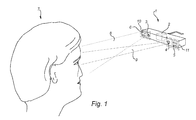
- Figure 1 shows a device 1 for acquiring a combined eye gaze image of an object 7 according to an embodiment of the present invention.
- the device is especially adapted for detection and analysis of eye gaze in dark-eye effect conditions.
- a device according to the invention may be implemented in many types of applications, such as integrated in a vehicle dashboard or at the screen of a personal computer. However, in the illustrated case the device 1 is shown directed at an object 7 without an application context.
- the device 1 comprises a control unit 2, a first camera 3, a second camera 4, a first light source 6 and a second light source 5.
- the first camera 3 and the second camera 4 are preferably electronic image sensor cameras, either of snapshot type or delivering a stream of consecutive images.
- the images can be in a digital format, e.g.
- each of the first light source 6 and the second light source 5 comprises four light emitting diodes (LEDs).
- the electromagnetic waves emitted by the LEDs can be of different types, including IR radiation.
- the waves are within a relatively narrow wave length range outside the range of visible light, and that each camera is provided with a band pass filter (not shown) corresponding to this range.
- the influence from the surrounding light is thereby further reduced, as many light sources (computer screens, fluorescent lamps, etc) practically only emit waves in the visible light range.
- the influence from other sources e.g.
- each light source preferably has as small aperture as possible, as this is distinguishable from illumination from another source.
- LEDs normally more than 20 LEDs may be arranged in a rectangular pattern. In one embodiment, it may be sufficient with fewer LEDs in each light source. The number of LEDs can range from one to 19.
- the quality of the combined eye gaze image is dependent upon the ability of the camera to capture high intensity "point" sources of radiation.
- the device 1 in the illustrated example is a rectangular box with a primary extension in the horizontal direction.
- the device 1 is arranged at a distance of about 0.5-1 m to the object 7.
- the first location 10 and the second location 11 are spaced apart a distance of 6-8 cm. This separating distance is enough to ensure that a light source active in one location will not result in a bright-eye effect for a camera in the other location, capturing an image frame of the object 7.
- the device 1 further comprises a control unit 2 to alternately illuminate 8 the object 7 with a light source in one location while capturing an image frame 9 with a camera in the other location.
- the control unit 2 activates the first light source 6 so that it emits light 8 (or IR radiation) at the object 7. Meanwhile the control unit 2 activates the second camera 4 to capture an image frame in its field of view 9.
- the control unit 2 is connected to the first camera 3, the second camera 4, the first light source 6, and the second light source 5 to provide each with activation signals and to receive image frames from the first camera 3 and the second camera 4.
- the activation signals to the light sources can be provided by alternatingly turning the first 6 and the second 5 light sources on and off.
- the control unit 2 alternatingly sends an activation signal to each camera during which the active camera is capturing an image frame.
- the control unit 2 is arranged to first activate the first camera 3 together with the second light source 5 to capture a first image frame. Subsequently the control unit will activate the second camera 4 together with the first light source 6 to capture a second image frame.
- the control unit 2 which has received each frame from the respective camera, can combine the information from each frame to provide a combined eye gaze image.
- the combined eye gaze image can be provided to an external unit (not shown) or alternatively be used in the control unit 2 to e.g. determine position, direction, etc. of the object's eyes.
- the device 1 can be said to have a central optical axis A which represents the optical axis of the provided combined eye gaze image.
- the first camera 3 has an optical axis B and the second camera 4 has an optical axis C, both optical axis B and optical axis C are in the illustrated example essentially parallel to each other in the horizontal plane as seen from the object in figure 1 .
- Preferably optical axes B and C converge slightly towards the central optical axis A, as shown in an exaggerated manner with axes C' and B'. This may improve the possibility to triangulate in the combined eye gaze image.
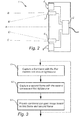
- a first frame is captured using the first camera and the second light source.
- a second frame is captured using the second camera and the first light source.
- an eye gaze image is provided as a combination of the information comprised in the first frame and in the second frame.
- the combined eye gaze image may comprise all information from the first frame and the second frame or the combined eye gaze image may comprise a smaller amount of selected or predetermined information from the first and the second frame.
- the smaller amount of selected or predetermined information is contains e.g. a black and white colorscale (i.e. greyscale), or just a predetermined wavelength spectrum.
- Fig. 4A a graph of the activation signals sent by the control unit 2 to each component of the system according to the method versus time is shown, at a time T0 the second light source 5 and the first camera 3 are activated whereby the first camera 3 captures a first frame at dark-eye conditions. Then, at a first transitional time T1 the second light source 5 and the first camera 3 is deactivated by the control unit 2, and the control unit 2 concurrently activates the first light source 6 and the second camera 4 to capture a second frame at dark-eye conditions. Further, at the second transitional time T2 the first light source 6 and the second camera 4 is deactivated. This process may then be repeated as long as a user or objects needs to be tracked, whereby e.g.
- an eye gaze may be tracked and the system provides a combined eye gaze image based on the first frame and the second frame comprising this information.
- the control unit may advantageously be adapted to introduce a pause after time T2 until the process is repeated, so that a predetermined image rate can be provided for each periodic cycle of time T0.
- Fig. 4B a transitional time period the second light source and first camera is shown in detail for a device according to one exemplary embodiment of the invention.
- the first 6 and second 5 light source may have illumination- and black-out delays that are both due to physical characteristics of a light source, when power is provided full illumination i.e. for a LED emittance of the maximum number of photons is not reached until a short time after activation of the LED.
- an activation offset is introduced for the second camera as shown in Fig. 4B in such a manner that the first camera may be initiated even during the preceding frame so that it is prepared and ready to capture the first frame when full illumination is provided by the second light source 5.
- the first light source should be non-emitting.
Priority Applications (4)
| Application Number | Priority Date | Filing Date | Title |
|---|---|---|---|
| EP13446504.6A EP2823751B1 (fr) | 2013-07-09 | 2013-07-09 | Imagerie du regard |
| PCT/EP2014/063921 WO2015003955A1 (fr) | 2013-07-09 | 2014-07-01 | Imagerie de regard |
| US14/902,653 US10007337B2 (en) | 2013-07-09 | 2014-07-01 | Eye gaze imaging |
| CN201480038445.7A CN105358045B (zh) | 2013-07-09 | 2014-07-01 | 眼凝视成像 |
Applications Claiming Priority (1)
| Application Number | Priority Date | Filing Date | Title |
|---|---|---|---|
| EP13446504.6A EP2823751B1 (fr) | 2013-07-09 | 2013-07-09 | Imagerie du regard |
Publications (2)
| Publication Number | Publication Date |
|---|---|
| EP2823751A1 true EP2823751A1 (fr) | 2015-01-14 |
| EP2823751B1 EP2823751B1 (fr) | 2023-07-05 |
Family
ID=48948373
Family Applications (1)
| Application Number | Title | Priority Date | Filing Date |
|---|---|---|---|
| EP13446504.6A Active EP2823751B1 (fr) | 2013-07-09 | 2013-07-09 | Imagerie du regard |
Country Status (4)
| Country | Link |
|---|---|
| US (1) | US10007337B2 (fr) |
| EP (1) | EP2823751B1 (fr) |
| CN (1) | CN105358045B (fr) |
| WO (1) | WO2015003955A1 (fr) |
Cited By (1)
| Publication number | Priority date | Publication date | Assignee | Title |
|---|---|---|---|---|
| EP3459436A1 (fr) | 2017-09-22 | 2019-03-27 | Smart Eye AB | Acquisition d'images avec réduction de réflexe |
Families Citing this family (12)
| Publication number | Priority date | Publication date | Assignee | Title |
|---|---|---|---|---|
| WO2015048026A1 (fr) * | 2013-09-24 | 2015-04-02 | Sony Computer Entertainment Inc. | Modifications de la poursuite du regard à l'aide d'une position d'éclairage dynamique |
| US9568603B2 (en) * | 2014-11-14 | 2017-02-14 | Microsoft Technology Licensing, Llc | Eyewear-mountable eye tracking device |
| US10043281B2 (en) | 2015-06-14 | 2018-08-07 | Sony Interactive Entertainment Inc. | Apparatus and method for estimating eye gaze location |
| US20170196496A1 (en) * | 2016-01-13 | 2017-07-13 | REBIScan, Inc. | Method and apparatus for fixation, alignment, and/or saccadic measurements to identify and/or track brain function |
| CN109716268B (zh) | 2016-09-22 | 2022-05-17 | 苹果公司 | 眼部和头部跟踪 |
| US10726574B2 (en) * | 2017-04-11 | 2020-07-28 | Dolby Laboratories Licensing Corporation | Passive multi-wearable-devices tracking |
| DE102017207206A1 (de) * | 2017-04-28 | 2018-10-31 | Robert Bosch Gmbh | Verfahren und Vorrichtung zum Ansteuern eines Fahrerbeobachtungssystems zum Beobachten eines Fahrers eines Fahrzeugs |
| KR102410834B1 (ko) | 2017-10-27 | 2022-06-20 | 삼성전자주식회사 | 반사 영역을 제거하는 방법, 사용자의 눈을 추적하는 방법 및 그 장치 |
| US10521013B2 (en) * | 2018-03-01 | 2019-12-31 | Samsung Electronics Co., Ltd. | High-speed staggered binocular eye tracking systems |
| EP3891018A4 (fr) * | 2018-12-05 | 2022-01-19 | Gentex Corporation | Système d'imagerie pour authentification d'iris et surveillance de conducteur |
| EP3666169A1 (fr) * | 2018-12-11 | 2020-06-17 | Aptiv Technologies Limited | Système de surveillance de conducteur |
| KR102435406B1 (ko) * | 2020-07-03 | 2022-08-24 | 현대모비스 주식회사 | 카메라 내장 램프의 비동기 제어 시스템 및 방법 |
Citations (6)
| Publication number | Priority date | Publication date | Assignee | Title |
|---|---|---|---|---|
| US20030098954A1 (en) * | 2001-04-27 | 2003-05-29 | International Business Machines Corporation | Calibration-free eye gaze tracking |
| EP1391176A1 (fr) * | 2002-08-16 | 2004-02-25 | Universiteit Maastricht | Procédé et dispositif pour mesurer la topographie d'une surface cornéenne |
| US20070279590A1 (en) * | 2003-12-25 | 2007-12-06 | Yoshinobu Ebisawa | Sight-Line Detection Method and Device, and Three-Dimensional View-Point Measurement Device |
| US20130107214A1 (en) * | 2009-04-01 | 2013-05-02 | Tobii Technology Ab | Adaptive Camera And Illuminator Eyetracker |
| WO2013066334A1 (fr) * | 2011-11-03 | 2013-05-10 | Intel Corporation | Capture d'image basée sur les mouvements oculaires |
| EP2604180A1 (fr) * | 2010-08-09 | 2013-06-19 | National University Corporation Shizuoka University | Procédé de détection de point de gaze et dispositif de détection de point de gaze |
Family Cites Families (4)
| Publication number | Priority date | Publication date | Assignee | Title |
|---|---|---|---|---|
| JP4500992B2 (ja) * | 2004-01-14 | 2010-07-14 | 国立大学法人静岡大学 | 三次元視点計測装置 |
| JP4888838B2 (ja) * | 2008-05-12 | 2012-02-29 | トヨタ自動車株式会社 | 運転者撮像装置および運転者撮像方法 |
| US10015380B2 (en) * | 2008-12-22 | 2018-07-03 | Ncr Corporation | Imaging system |
| CN103054548A (zh) * | 2012-07-05 | 2013-04-24 | 东北电力大学 | 凝视点测量装置及瞳孔、普尔钦亮斑识别方法 |
-
2013
- 2013-07-09 EP EP13446504.6A patent/EP2823751B1/fr active Active
-
2014
- 2014-07-01 WO PCT/EP2014/063921 patent/WO2015003955A1/fr active Application Filing
- 2014-07-01 US US14/902,653 patent/US10007337B2/en active Active
- 2014-07-01 CN CN201480038445.7A patent/CN105358045B/zh active Active
Patent Citations (6)
| Publication number | Priority date | Publication date | Assignee | Title |
|---|---|---|---|---|
| US20030098954A1 (en) * | 2001-04-27 | 2003-05-29 | International Business Machines Corporation | Calibration-free eye gaze tracking |
| EP1391176A1 (fr) * | 2002-08-16 | 2004-02-25 | Universiteit Maastricht | Procédé et dispositif pour mesurer la topographie d'une surface cornéenne |
| US20070279590A1 (en) * | 2003-12-25 | 2007-12-06 | Yoshinobu Ebisawa | Sight-Line Detection Method and Device, and Three-Dimensional View-Point Measurement Device |
| US20130107214A1 (en) * | 2009-04-01 | 2013-05-02 | Tobii Technology Ab | Adaptive Camera And Illuminator Eyetracker |
| EP2604180A1 (fr) * | 2010-08-09 | 2013-06-19 | National University Corporation Shizuoka University | Procédé de détection de point de gaze et dispositif de détection de point de gaze |
| WO2013066334A1 (fr) * | 2011-11-03 | 2013-05-10 | Intel Corporation | Capture d'image basée sur les mouvements oculaires |
Cited By (3)
| Publication number | Priority date | Publication date | Assignee | Title |
|---|---|---|---|---|
| EP3459436A1 (fr) | 2017-09-22 | 2019-03-27 | Smart Eye AB | Acquisition d'images avec réduction de réflexe |
| WO2019057766A1 (fr) | 2017-09-22 | 2019-03-28 | Smart Eye Ab | Acquisition d'image assortie de réduction de réflexions |
| US11653832B2 (en) | 2017-09-22 | 2023-05-23 | Smart Eye Ab | Image acquisition with reflex reduction |
Also Published As
| Publication number | Publication date |
|---|---|
| CN105358045A (zh) | 2016-02-24 |
| US10007337B2 (en) | 2018-06-26 |
| CN105358045B (zh) | 2018-03-20 |
| EP2823751B1 (fr) | 2023-07-05 |
| US20160170486A1 (en) | 2016-06-16 |
| WO2015003955A1 (fr) | 2015-01-15 |
Similar Documents
| Publication | Publication Date | Title |
|---|---|---|
| US10007337B2 (en) | Eye gaze imaging | |
| CN108513078B (zh) | 用于通过深度传感相机使用光发射在弱光条件下捕获视频影像的方法和系统 | |
| CN108370438B (zh) | 范围选通的深度相机组件 | |
| US8890946B2 (en) | Systems and methods for spatially controlled scene illumination | |
| US7430365B2 (en) | Safe eye detection | |
| EP2748797B1 (fr) | Détermination de la distance à un objet à partir d'une image | |
| US20080186449A1 (en) | Gaze tracking using multiple images | |
| US20220197376A1 (en) | Event camera system for pupil detection and eye tracking | |
| US20040037450A1 (en) | Method, apparatus and system for using computer vision to identify facial characteristics | |
| JP2016532396A (ja) | 低電力眼追跡システムおよび眼追跡方法 | |
| JP5643153B2 (ja) | 光投影装置 | |
| KR20160050755A (ko) | 전자 장치 및 그의 홍채 인식 방법 | |
| CN110312079A (zh) | 图像采集装置及其应用系统 | |
| US11363211B2 (en) | Image generation control device, image generation control method, and image generation control program | |
| US11653832B2 (en) | Image acquisition with reflex reduction | |
| US9654703B2 (en) | Illumination apparatus | |
| KR101450119B1 (ko) | 카메라의 조명모듈 제어 방법 및 그 장치 | |
| US11144755B2 (en) | Support glint for remote eye tracking | |
| JP2010134363A (ja) | 照明制御装置および方法 | |
| US20220272256A1 (en) | Information processing device, visual line detection system, visual line detection method, and visual line detection program | |
| JP6370168B2 (ja) | 照明撮像装置及びそれを備えた視線検出装置 |
Legal Events
| Date | Code | Title | Description |
|---|---|---|---|
| 17P | Request for examination filed |
Effective date: 20130709 |
|
| AK | Designated contracting states |
Kind code of ref document: A1 Designated state(s): AL AT BE BG CH CY CZ DE DK EE ES FI FR GB GR HR HU IE IS IT LI LT LU LV MC MK MT NL NO PL PT RO RS SE SI SK SM TR |
|
| AX | Request for extension of the european patent |
Extension state: BA ME |
|
| PUAI | Public reference made under article 153(3) epc to a published international application that has entered the european phase |
Free format text: ORIGINAL CODE: 0009012 |
|
| R17P | Request for examination filed (corrected) |
Effective date: 20150701 |
|
| RBV | Designated contracting states (corrected) |
Designated state(s): AL AT BE BG CH CY CZ DE DK EE ES FI FR GB GR HR HU IE IS IT LI LT LU LV MC MK MT NL NO PL PT RO RS SE SI SK SM TR |
|
| STAA | Information on the status of an ep patent application or granted ep patent |
Free format text: STATUS: EXAMINATION IS IN PROGRESS |
|
| 17Q | First examination report despatched |
Effective date: 20171218 |
|
| STAA | Information on the status of an ep patent application or granted ep patent |
Free format text: STATUS: EXAMINATION IS IN PROGRESS |
|
| STAA | Information on the status of an ep patent application or granted ep patent |
Free format text: STATUS: EXAMINATION IS IN PROGRESS |
|
| REG | Reference to a national code |
Ref document number: 602013084159 Country of ref document: DE Ref country code: DE Ref legal event code: R079 Free format text: PREVIOUS MAIN CLASS: A61B0003000000 Ipc: A61B0003113000 |
|
| RIC1 | Information provided on ipc code assigned before grant |
Ipc: G06V 40/19 20220101ALI20221222BHEP Ipc: G06F 3/01 20060101ALI20221222BHEP Ipc: A61B 3/113 20060101AFI20221222BHEP |
|
| GRAP | Despatch of communication of intention to grant a patent |
Free format text: ORIGINAL CODE: EPIDOSNIGR1 |
|
| STAA | Information on the status of an ep patent application or granted ep patent |
Free format text: STATUS: GRANT OF PATENT IS INTENDED |
|
| INTG | Intention to grant announced |
Effective date: 20230224 |
|
| GRAS | Grant fee paid |
Free format text: ORIGINAL CODE: EPIDOSNIGR3 |
|
| GRAA | (expected) grant |
Free format text: ORIGINAL CODE: 0009210 |
|
| STAA | Information on the status of an ep patent application or granted ep patent |
Free format text: STATUS: THE PATENT HAS BEEN GRANTED |
|
| AK | Designated contracting states |
Kind code of ref document: B1 Designated state(s): AL AT BE BG CH CY CZ DE DK EE ES FI FR GB GR HR HU IE IS IT LI LT LU LV MC MK MT NL NO PL PT RO RS SE SI SK SM TR |
|
| REG | Reference to a national code |
Ref country code: CH Ref legal event code: EP |
|
| REG | Reference to a national code |
Ref country code: AT Ref legal event code: REF Ref document number: 1584034 Country of ref document: AT Kind code of ref document: T Effective date: 20230715 |
|
| REG | Reference to a national code |
Ref country code: DE Ref legal event code: R096 Ref document number: 602013084159 Country of ref document: DE |
|
| PGFP | Annual fee paid to national office [announced via postgrant information from national office to epo] |
Ref country code: FR Payment date: 20230629 Year of fee payment: 11 |
|
| P01 | Opt-out of the competence of the unified patent court (upc) registered |
Effective date: 20230627 |
|
| REG | Reference to a national code |
Ref country code: IE Ref legal event code: FG4D |
|
| REG | Reference to a national code |
Ref country code: LT Ref legal event code: MG9D |
|
| PGFP | Annual fee paid to national office [announced via postgrant information from national office to epo] |
Ref country code: GB Payment date: 20230705 Year of fee payment: 11 |
|
| REG | Reference to a national code |
Ref country code: NL Ref legal event code: MP Effective date: 20230705 |
|
| PGFP | Annual fee paid to national office [announced via postgrant information from national office to epo] |
Ref country code: DE Payment date: 20230616 Year of fee payment: 11 |
|
| REG | Reference to a national code |
Ref country code: AT Ref legal event code: MK05 Ref document number: 1584034 Country of ref document: AT Kind code of ref document: T Effective date: 20230705 |
|
| PG25 | Lapsed in a contracting state [announced via postgrant information from national office to epo] |
Ref country code: NL Free format text: LAPSE BECAUSE OF FAILURE TO SUBMIT A TRANSLATION OF THE DESCRIPTION OR TO PAY THE FEE WITHIN THE PRESCRIBED TIME-LIMIT Effective date: 20230705 |
|
| PG25 | Lapsed in a contracting state [announced via postgrant information from national office to epo] |
Ref country code: GR Free format text: LAPSE BECAUSE OF FAILURE TO SUBMIT A TRANSLATION OF THE DESCRIPTION OR TO PAY THE FEE WITHIN THE PRESCRIBED TIME-LIMIT Effective date: 20231006 |
|
| PG25 | Lapsed in a contracting state [announced via postgrant information from national office to epo] |
Ref country code: ES Free format text: LAPSE BECAUSE OF FAILURE TO SUBMIT A TRANSLATION OF THE DESCRIPTION OR TO PAY THE FEE WITHIN THE PRESCRIBED TIME-LIMIT Effective date: 20230705 |
|
| PG25 | Lapsed in a contracting state [announced via postgrant information from national office to epo] |
Ref country code: IS Free format text: LAPSE BECAUSE OF FAILURE TO SUBMIT A TRANSLATION OF THE DESCRIPTION OR TO PAY THE FEE WITHIN THE PRESCRIBED TIME-LIMIT Effective date: 20231105 |
|
| PG25 | Lapsed in a contracting state [announced via postgrant information from national office to epo] |
Ref country code: SE Free format text: LAPSE BECAUSE OF FAILURE TO SUBMIT A TRANSLATION OF THE DESCRIPTION OR TO PAY THE FEE WITHIN THE PRESCRIBED TIME-LIMIT Effective date: 20230705 Ref country code: RS Free format text: LAPSE BECAUSE OF FAILURE TO SUBMIT A TRANSLATION OF THE DESCRIPTION OR TO PAY THE FEE WITHIN THE PRESCRIBED TIME-LIMIT Effective date: 20230705 Ref country code: PT Free format text: LAPSE BECAUSE OF FAILURE TO SUBMIT A TRANSLATION OF THE DESCRIPTION OR TO PAY THE FEE WITHIN THE PRESCRIBED TIME-LIMIT Effective date: 20231106 Ref country code: NO Free format text: LAPSE BECAUSE OF FAILURE TO SUBMIT A TRANSLATION OF THE DESCRIPTION OR TO PAY THE FEE WITHIN THE PRESCRIBED TIME-LIMIT Effective date: 20231005 Ref country code: LV Free format text: LAPSE BECAUSE OF FAILURE TO SUBMIT A TRANSLATION OF THE DESCRIPTION OR TO PAY THE FEE WITHIN THE PRESCRIBED TIME-LIMIT Effective date: 20230705 Ref country code: LT Free format text: LAPSE BECAUSE OF FAILURE TO SUBMIT A TRANSLATION OF THE DESCRIPTION OR TO PAY THE FEE WITHIN THE PRESCRIBED TIME-LIMIT Effective date: 20230705 Ref country code: IS Free format text: LAPSE BECAUSE OF FAILURE TO SUBMIT A TRANSLATION OF THE DESCRIPTION OR TO PAY THE FEE WITHIN THE PRESCRIBED TIME-LIMIT Effective date: 20231105 Ref country code: HR Free format text: LAPSE BECAUSE OF FAILURE TO SUBMIT A TRANSLATION OF THE DESCRIPTION OR TO PAY THE FEE WITHIN THE PRESCRIBED TIME-LIMIT Effective date: 20230705 Ref country code: GR Free format text: LAPSE BECAUSE OF FAILURE TO SUBMIT A TRANSLATION OF THE DESCRIPTION OR TO PAY THE FEE WITHIN THE PRESCRIBED TIME-LIMIT Effective date: 20231006 Ref country code: FI Free format text: LAPSE BECAUSE OF FAILURE TO SUBMIT A TRANSLATION OF THE DESCRIPTION OR TO PAY THE FEE WITHIN THE PRESCRIBED TIME-LIMIT Effective date: 20230705 Ref country code: ES Free format text: LAPSE BECAUSE OF FAILURE TO SUBMIT A TRANSLATION OF THE DESCRIPTION OR TO PAY THE FEE WITHIN THE PRESCRIBED TIME-LIMIT Effective date: 20230705 Ref country code: AT Free format text: LAPSE BECAUSE OF FAILURE TO SUBMIT A TRANSLATION OF THE DESCRIPTION OR TO PAY THE FEE WITHIN THE PRESCRIBED TIME-LIMIT Effective date: 20230705 |
|
| PG25 | Lapsed in a contracting state [announced via postgrant information from national office to epo] |
Ref country code: PL Free format text: LAPSE BECAUSE OF FAILURE TO SUBMIT A TRANSLATION OF THE DESCRIPTION OR TO PAY THE FEE WITHIN THE PRESCRIBED TIME-LIMIT Effective date: 20230705 |
|
| REG | Reference to a national code |
Ref country code: CH Ref legal event code: PL |
|
| REG | Reference to a national code |
Ref country code: BE Ref legal event code: MM Effective date: 20230731 |
|
| PG25 | Lapsed in a contracting state [announced via postgrant information from national office to epo] |
Ref country code: LU Free format text: LAPSE BECAUSE OF NON-PAYMENT OF DUE FEES Effective date: 20230709 |
|
| PG25 | Lapsed in a contracting state [announced via postgrant information from national office to epo] |
Ref country code: LU Free format text: LAPSE BECAUSE OF NON-PAYMENT OF DUE FEES Effective date: 20230709 |