EP2823544B1 - Method of fault clearance - Google Patents
Method of fault clearance Download PDFInfo
- Publication number
- EP2823544B1 EP2823544B1 EP13706977.9A EP13706977A EP2823544B1 EP 2823544 B1 EP2823544 B1 EP 2823544B1 EP 13706977 A EP13706977 A EP 13706977A EP 2823544 B1 EP2823544 B1 EP 2823544B1
- Authority
- EP
- European Patent Office
- Prior art keywords
- power transmission
- fault
- circuit interruption
- interruption device
- transmission medium
- Prior art date
- Legal status (The legal status is an assumption and is not a legal conclusion. Google has not performed a legal analysis and makes no representation as to the accuracy of the status listed.)
- Active
Links
Images


Classifications
-
- H—ELECTRICITY
- H02—GENERATION; CONVERSION OR DISTRIBUTION OF ELECTRIC POWER
- H02H—EMERGENCY PROTECTIVE CIRCUIT ARRANGEMENTS
- H02H7/00—Emergency protective circuit arrangements specially adapted for specific types of electric machines or apparatus or for sectionalised protection of cable or line systems, and effecting automatic switching in the event of an undesired change from normal working conditions
- H02H7/26—Sectionalised protection of cable or line systems, e.g. for disconnecting a section on which a short-circuit, earth fault, or arc discharge has occured
- H02H7/268—Sectionalised protection of cable or line systems, e.g. for disconnecting a section on which a short-circuit, earth fault, or arc discharge has occured for DC systems
-
- H—ELECTRICITY
- H02—GENERATION; CONVERSION OR DISTRIBUTION OF ELECTRIC POWER
- H02H—EMERGENCY PROTECTIVE CIRCUIT ARRANGEMENTS
- H02H3/00—Emergency protective circuit arrangements for automatic disconnection directly responsive to an undesired change from normal electric working condition with or without subsequent reconnection ; integrated protection
- H02H3/02—Details
- H02H3/06—Details with automatic reconnection
-
- H—ELECTRICITY
- H02—GENERATION; CONVERSION OR DISTRIBUTION OF ELECTRIC POWER
- H02H—EMERGENCY PROTECTIVE CIRCUIT ARRANGEMENTS
- H02H7/00—Emergency protective circuit arrangements specially adapted for specific types of electric machines or apparatus or for sectionalised protection of cable or line systems, and effecting automatic switching in the event of an undesired change from normal working conditions
- H02H7/26—Sectionalised protection of cable or line systems, e.g. for disconnecting a section on which a short-circuit, earth fault, or arc discharge has occured
- H02H7/261—Sectionalised protection of cable or line systems, e.g. for disconnecting a section on which a short-circuit, earth fault, or arc discharge has occured involving signal transmission between at least two stations
-
- H—ELECTRICITY
- H02—GENERATION; CONVERSION OR DISTRIBUTION OF ELECTRIC POWER
- H02H—EMERGENCY PROTECTIVE CIRCUIT ARRANGEMENTS
- H02H9/00—Emergency protective circuit arrangements for limiting excess current or voltage without disconnection
- H02H9/02—Emergency protective circuit arrangements for limiting excess current or voltage without disconnection responsive to excess current
Definitions
- This invention relates to a method of fault clearance for a DC power grid.
- HVDC high voltage direct current
- a DC power grid requires multi-terminal interconnection of HVDC converters, whereby power can be exchanged on the DC side using three or more HVDC converters operating in parallel.
- Each HVDC converter acts as either a source or sink to maintain the overall input-to-output power balance of the network whilst exchanging the power as required.
- US 3,970,898 discloses a method of and an apparatus for automatically isolating a faulty section of a power line of an electrical supply network.
- the power line is adapted to be connected to at least one energy source and to be temporarily divided up into sections by switches following the appearance of an excess current, and automatically reconnecting normally operating sections of the power line to at least one energy source.
- a signal is transmitted from the place of at least one switch, which has opened automatically after an excess current that has passed through it.
- the signal is transmitted through a non-faulty part of the power line to at least one other switch, through which at least part of the excess current had passed to the now opened switch and which has automatically opened as well. Reception of the signal is an essential requirement for closing the other switch.
- a method of fault clearance for a DC power grid wherein the DC power grid includes: a plurality of DC terminals; a plurality of DC power transmission media to interconnect the plurality of DC terminals; and a plurality of DC circuit interruption device stations, each DC circuit interruption device station being associated with a respective one of the plurality of DC power transmission media and a respective one of the plurality of DC terminals, each DC circuit interruption device station including a DC circuit interruption device to selectively interrupt current flow in the associated power transmission medium, the method comprising the steps of:
- opening a circuit interruption device refers to the use of the circuit interruption device to open a closed circuit to interrupt current flow in the circuit
- closing a circuit interruption device refers to the use of the circuit interruption device to complete an open circuit to permit current flow in the circuit
- a DC circuit interruption device may be any device that is capable of interrupting direct current flow in a DC circuit.
- a DC circuit interruption device may be, but is not limited to, a DC circuit breaker.
- a DC power transmission medium may be any medium that is capable of transmitting electrical power between two or more DC terminals.
- a medium may be, but is not limited to, a submarine DC power transmission cable, an overhead DC power transmission line or cable and an underground DC power transmission cable.
- the occurrence of one or more faults occurring in the plurality of the DC power transmission media may lead to one or more fault currents flowing through the DC power grid.
- the fault may, for example, be in the form of a short circuit with low impedance across DC power transmission cables. This may occur due to damage or breakdown of insulation, lightning strikes, movement of conductors or other accidental bridging between conductors by a foreign object.
- Detection of the or each fault may be carried out locally at each DC circuit interruption device station to enable rapid detection of a fault in the associated DC power transmission medium. Such rapid detection may be achieved by, for example, using an embodiment of the method in which the step of detecting a fault occurring in the plurality of DC power transmission media involves carrying out direct or derivative measurements of current and/or voltage characteristics of the associated DC power transmission medium.
- each DC circuit interruption device station includes fault detection equipment to detect one or more faults in the associated DC power transmission medium, wherein each DC circuit interruption device opens in response to detection of the or each fault in the plurality of DC power transmission media by the fault detection equipment of the corresponding DC circuit interruption device station.
- a DC circuit interruption device is usually designed to open on command, i.e. trip, upon detection of a fault in a circuit directly connected to the DC circuit interruption device.
- the low impedance nature of the DC power grid results in all DC terminals of the DC power grid being affected by the or each fault occurring in the plurality of DC power transmission media. This causes the or each fault to be detected locally at each DC circuit interruption device station. In the method according to the invention, this will automatically cause each DC circuit interruption device to trip.
- Opening all of the DC circuit interruption devices upon detection of the or fault occurring in the plurality of DC power transmission media enables speedy interruption of the or each fault current in the DC power grid, whilst the or each fault current is still within the current interruption capability of each DC circuit interruption device. This prevents a rise in level of the or each fault current until it exceeds the current interruption capability of each DC circuit interruption device. In the event a fault current exceeds the current interruption capability of a DC circuit interruption device, it is not possible to open the DC circuit interruption device.
- Figure 1 illustrates the relative magnitudes of current in a DC power grid. It can be seen that, during a fault in the DC power grid, a DC power transmission medium current with a normal operating value of 1.0 per unit current may exceed the current interruption capability of a typical DC circuit breaker with a 6.0 per unit current rating within 5 ms, and may reach a DC converter fault current of 10.0 per unit current within 10 ms and a DC power grid fault current of several multiples of the DC converter fault current within 50 ms. It is therefore essential to open all of the DC circuit interruption devices immediately after the or each fault is detected, in order to ensure successful interruption of current flow in the DC power grid.
- the step of opening all of the DC circuit interruption devices after detection of the or each fault is further advantageous in that this step obviates the need to operate AC circuit breakers to interrupt current flow in the DC power grid, which adversely impacts the duration of complete power transmission capability through the DC power grid.
- This is because, in many conventional converter topologies, the use of diodes forming part of power transistors for use in power electronic switches results in an inherent conduction path through a converter. Hence, in the event of a fault in the DC power grid, discharge current may flow through the conduction path from the AC power grid and into the fault via the DC power grid.
- the flow of discharge current means that circuit isolating switches cannot be opened to isolate the faulty section of the DC power grid until the magnitude of the discharge current has fallen below the current interruption capability of the circuit isolating switches. It is therefore necessary to first trip all AC circuit breakers connected to all converters of the DC power grid to isolate the converter from an associated AC network before using circuit isolating switches to disconnect a faulty section of the DC power grid and then re-energising the remaining parts of the DC power grid. Isolating the converter from its associated AC network and then reclosing the AC circuit breaker to reconnect the converter would however take a finite period of time. Typically AC circuit breakers can trip quickly but can however take three or four times longer to reclose.
- Identification of the or each faulty DC power transmission medium in which the or each fault is located is carried out after all of the DC circuit interruption devices have been opened. This is possible because each faulty DC power transmission medium will be subjected to a low impedance and will typically have, on average, a zero residual DC voltage level. Meanwhile each non-faulty DC power transmission medium will have a non-zero residual DC voltage level due to the presence of trapped charge. Such differences in the electrical characteristics of the faulty and non-faulty DC power transmission media are readily measured to provide information that makes it straightforward to identify the or each faulty DC power transmission medium.
- Measurement of electrical characteristics of each DC power transmission medium may be done locally at each DC circuit interruption device station without the need for communication between different DC circuit interruption device stations or with a central control station, thus resulting in a straightforward and rapid identification of the or each faulty DC power transmission medium. This has the benefit of minimising the amount of time of zero power transmission in the DC power grid, which minimises inconvenience to the DC power grid's end users.
- the step of measuring electrical characteristics of each DC power transmission medium may be carried out in a number of different ways after all of the DC circuit interruption devices have been opened.
- the step of measuring electrical characteristics of each DC power transmission medium may involve measuring a residual DC voltage level of each DC power transmission medium.
- the step of measuring electrical characteristics of each DC power transmission medium may involve measuring a voltage oscillation frequency of each DC power transmission medium.
- Measurement of voltage characteristics of each DC power transmission medium in this manner permits the or each faulty DC power transmission medium to be identified.
- the step of measuring electrical characteristics of each DC power transmission medium may involve measuring differences in fault current magnitude and direction in the plurality of DC power transmission media.
- the step of identifying the or each faulty DC power transmission medium, in which the or each fault is located, based on the measured electrical characteristics of the plurality of DC power transmission media may involve communicating information between different DC circuit interruption device stations, the information including differences in fault current magnitude and direction in the plurality of DC power transmission media.
- the step of identifying the or each faulty DC power transmission medium, in which the or each fault is located, based on the measured electrical characteristics of the plurality of DC power transmission media may involve communicating information between each DC circuit interruption device station and a control station, the information including differences in fault current magnitude and direction in the plurality of DC power transmission media.
- Measurement of differences in fault current magnitude and direction in the plurality of DC transmission media also permits the or each faulty DC power transmission medium to be identified.
- the step of identifying the or each faulty DC power transmission medium, in which the or each fault is located, based on the measured electrical characteristics of the plurality of DC power transmission media may involve determining a location of the or each fault within the or each faulty DC power transmission medium.
- Measurement of the voltage characteristics of each DC power transmission medium may allow the location of the fault within the or each faulty DC power transmission medium to be identified.
- the or each DC circuit interruption device associated with the or each faulty DC power transmission media is inhibited from closing to prevent the or each fault current from flowing within the DC power grid, while normal operation of the or each non-faulty DC power transmission media is resumed by closing the or each corresponding DC circuit interruption device.
- the DC power grid may be operated to carry out the steps of inhibiting closing of and opening of each DC circuit interruption device in a number of different ways after the or each faulty DC power transmission medium has been identified.
- the step of closing the or each DC circuit interruption device that is associated with the or each non-faulty DC power transmission medium, in which the or each fault is not located may involve sending a control signal from the control station to the or each DC circuit interruption device station that is associated with the or each non-faulty DC power transmission medium to initiate closing of the or each corresponding DC circuit interruption device.
- the step of closing the or each DC circuit interruption device that is associated with the or each non-faulty DC power transmission medium, in which the or each fault is not located involves closing the or each DC circuit interruption device that is associated with the or each non-faulty DC power transmission medium after a predetermined time delay after the opening of the DC circuit interruption devices of the corresponding DC circuit interruption device stations at which the or each fault is detected.
- each DC circuit interruption device automatically closes after the predetermined time delay, it is necessary to actively inhibit the or each DC circuit interruption device that is associated with the or each faulty DC power transmission medium.
- Active inhibition of the closing of the or each DC circuit interruption device that is associated with the or each faulty DC power transmission medium may be achieved using local control at the corresponding DC circuit interruption device station.
- the DC power grid further includes a control station to communicate with the plurality of DC circuit interruption device stations
- the step of inhibiting closing of the or each DC circuit interruption device that is associated with the or each faulty DC power transmission medium in which the or each fault is located may involve sending a control signal from the control station to the or each DC circuit interruption device station that is associated with the or each faulty DC power transmission medium to inhibit closing of the or each corresponding DC circuit interruption device.
- a method of fault clearance for a DC power grid 10 according to an embodiment of the invention is described as follows, with reference to Figures 2 to 5 .
- a DC power grid 10 includes four DC terminals 12a,12b,12c,12d and four DC power transmission lines 14a,14b,14c,14d.
- Each DC terminal 12a,12b,12c,12d is connected to a power converter 16a,16b,16c,16d, while the four DC power transmission lines 14a,14b,14c,14d are arranged to interconnect the DC terminals, as follows.
- a first end of a first DC power transmission line 14a is connected to a first DC terminal 12a, while a second end of the first DC power transmission line 14a is connected to a second DC terminal 12b.
- a first end of a second DC power transmission line 14b is connected to the second DC terminal 12b, while a second end of the second DC power transmission line 14b is connected to a third DC terminal 12c.
- a first end of a third DC power transmission line 14c is connected to the third DC terminal 12c, while a second end of the third DC power transmission line 14c is connected to a fourth DC terminal 12d.
- a first end of a fourth DC power transmission line 14d is connected to the fourth DC terminal 12d, while a second end of the fourth DC power transmission line 14d is connected to the first DC terminal 12a.
- DC power transmission lines 14a,14b,14c,14d to interconnect the four DC terminals 12a,12b,12c,12d permits power transfer between the different DC terminals 12a,12b,12c,12d of the DC power grid 10.
- the DC power grid 10 further includes a plurality of DC circuit breaker stations 18.
- Each DC circuit breaker station 18 includes a DC circuit breaker 20 that is connected between a respective one of the DC terminals 12a,12b,12c,12d and one end of a respective one of the DC power transmission lines 14a,14b,14c,14d, so that a pair of DC circuit breakers 20 is located at opposite ends of each DC power transmission line 14a,14b,14c,14d.
- each DC circuit breaker 20 may be replaced by another type of circuit interruption device.
- Configuration of the DC power grid 10 in this manner allows each DC circuit breaker 20 to selectively interrupt current flow in the corresponding DC power transmission line 14a,14b,14c,14d, i.e. each DC circuit breaker 20 is controlled to either interrupt or permit current flow in the corresponding DC power transmission line 14a,14b,14c,14d.
- the DC power grid 10 further includes a plurality of DC reactors 22.
- Each DC reactor 22 is connected between a respective one of the DC circuit breakers 20 and one end of a respective one of the DC power transmission lines 14a,14b,14c,14d, so that a pair of DC reactors 22 is located at opposite ends of each DC power transmission line 14a,14b,14c,14d.
- the purpose of the DC reactors 22 is to limit the rate of change of direct current flow in the corresponding DC power transmission line 14a,14b,14c,14d.
- the DC reactors 22 may be omitted.
- Each DC circuit breaker station 18 further includes fault detection equipment (not shown) to locally carry out direct or derivative measurements of current and voltage characteristics of the corresponding DC power transmission line 14a,14b,14c,14d. This allows a fault occurring in the corresponding DC power transmission line 14a,14b,14c,14d to be rapidly detected when the fault results in the measured current and voltage characteristics falling outside their normal operating ranges. Each DC circuit breaker 20 trips when a fault is detected by the fault detection equipment of the corresponding DC circuit breaker station 18.
- Each power converter 16a,16b,16c,16d is further connected to a respective AC network 24 via a respective AC circuit breaker 26.
- the pole-to-pole fault was initiated so as to occur at the centre of the fourth DC power transmission line 14d.
- the low impedance nature of the DC power grid 10 results in all of the DC terminals 12a,12b,12c,12d of the DC power grid 10 being affected by the pole-to-pole fault applied to the fourth DC power transmission line 14d. This in turn allows the fault detection equipment of each DC circuit breaker station 18 to locally detect the occurrence of the pole-to-pole fault, and thereby cause all of the DC circuit breakers 20 to automatically trip.
- opening all the DC circuit breakers 20 after detection of the fault prevents a resulting fault current from rising to a level where it exceeds the current interruption capability of each DC circuit breaker 20. This in turn prevents the DC power grid 10 from being exposed to high fault current that cannot be interrupted.
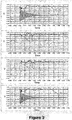
- the graphs shown in Figure 3 illustrates voltage characteristics V 1 ,V 2 ,V 3 ,V 4 for each DC power transmission line 14a,14b,14c,14d, as measured by the fault detection equipment of each DC circuit breaker station 18, before and after the occurrence of the pole-to-pole fault in the first simulation.
- the voltage level V 4 in the fourth DC power transmission line 14d was found to have a zero residual DC voltage in the form of a nominally zero DC voltage with a substantial AC voltage component.
- the DC circuit breakers 20 connected to the fourth DC power transmission line 14d were inhibited from re-closing, while the DC circuit breakers 20 connected to the first, second and third DC power transmission lines 14a, 14b, 14c were closed. This therefore enables the first, second and third DC power transmission lines 14a,14b,14c to resume normal operation, whilst the fourth DC power transmission line 14d is kept off-line to allow the pole-to-pole fault to be repaired or removed.
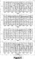
- the pole-to-pole fault was initiated so as to occur at the first end of the fourth DC power transmission line 14d.
- the graphs shown in Figure 5 illustrates voltage characteristics V 1 ,V 2 ,V 3 ,V 4 for each DC power transmission line 14a,14b,14c,14d, as measured by the fault detection equipment of each DC circuit breaker station 18, before and after the occurrence of the pole-to-pole fault in the second simulation.
- the fault detection equipment of the DC circuit breaker station 18 measures the voltage V 4 at the second end of the fourth DC power transmission line 14d to be a zero residual DC voltage V 42 in the form of a nominally zero DC voltage with a substantial AC voltage component in the fourth DC power transmission line 14d. Meanwhile the fault detection equipment of the DC circuit breaker station 18 measures the voltage V 4 at the first end of the DC fourth power transmission line 14d to be a zero residual DC voltage V 41 without an AC voltage component.
- the measured voltage characteristics of the DC power transmission lines 14a,14b,14c,14d may be used to determine the location of the fault at any location within a faulty DC power transmission line.
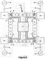
- a method of fault clearance for a DC power grid 110 according to a second embodiment of the invention is described as follows, with reference to Figure 6 .
- the DC power grid 110 of Figure 6 is similar in structure and operation to the DC power grid 10 of Figure 2 , and like features share the same reference numerals.
- the DC power grid 110 of Figure 6 differs from the DC power grid 10 of Figure 2 in that the DC power grid 110 of Figure 6 further includes a control station 30 to communicate with each DC circuit breaker station 18.
- the method according to the second embodiment of the invention is similar to the method according to the first embodiment of the invention except that, in the second method, the faulty DC power transmission medium in the DC power grid 110 of Figure 6 is identified by measuring magnitude and direction of fault current flowing in the DC power grid 110, instead of measuring voltage characteristics of each DC power transmission line 14a,14b,14c,14d.
- the fault detection equipment of each DC circuit breaker station 18 not only detects the pole-to-pole fault, but also measures the magnitude and direction of fault current flowing through the corresponding DC power transmission line 14a,14b,14c,14d.
- both ends of the fourth DC power transmission line 14d will experience inflow of fault current. Meanwhile one end of each of the first, second and third DC power transmission lines 14a,14b,14c will experience inflow of fault current, while the other end of each of the first, second and third DC power transmission lines 14a,14b,14c will experience outflow of current.
- each DC circuit breaker station 18 communicates information to the other DC circuit breaker stations 18 via the control station 30.
- the communicated information includes the earlier-measured magnitudes and directions of fault current flowing in the DC power transmission lines 14a,14b,14c,14d.
- the differences in fault current magnitude and direction in the fourth DC power transmission line 14d and the other DC power transmission lines 14a,14b,14c allows the fourth DC power transmission line 14d to be identified as the faulty DC power transmission line in which the pole-to-pole fault is located.
- the DC circuit breakers 20 connected to the fourth DC power transmission line 14d are inhibited from re-closing, while the DC circuit breakers 20 connected to the first, second and third DC power transmission lines 14a,14b,14c are closed. This therefore enables the first, second and third DC power transmission lines 14a,14b,14c to resume normal operation, whilst the fourth DC power transmission line 14d is kept off-line to allow the pole-to-pole fault to be repaired or removed.
- the DC power grid 110 may omit the control station 30, and each DC circuit breaker station 18 may directly communicate the information to the other DC circuit breaker stations 18 after all of the DC circuit breakers 20 are opened.
- the first and second methods may be used in combination to clear one or more faults in a DC power grid.
- a DC power grid having a different number of DC terminals and a different arrangement of DC power transmission lines to interconnect the DC terminals.
- a DC power grid may be, but is not limited to, a mesh-connected DC power grid or a radial-connected DC power grid.
- DC power transmission lines 14a,14b,14c,14d refer to the use of DC power transmission lines 14a,14b,14c,14d. It is envisaged that, in other embodiments, the method may be used in DC power grids including other DC power transmission media such as, for example, a submarine DC power transmission cable, an overhead DC power transmission line or cable and an underground DC power transmission cable.
Landscapes
- Engineering & Computer Science (AREA)
- Power Engineering (AREA)
- Direct Current Feeding And Distribution (AREA)
- Emergency Protection Circuit Devices (AREA)
Applications Claiming Priority (2)
| Application Number | Priority Date | Filing Date | Title |
|---|---|---|---|
| GB201203785A GB2501057B (en) | 2012-03-05 | 2012-03-05 | Method of fault clearance |
| PCT/EP2013/053834 WO2013131782A1 (en) | 2012-03-05 | 2013-02-26 | Method of fault clearance |
Publications (2)
| Publication Number | Publication Date |
|---|---|
| EP2823544A1 EP2823544A1 (en) | 2015-01-14 |
| EP2823544B1 true EP2823544B1 (en) | 2016-06-15 |
Family
ID=46003093
Family Applications (1)
| Application Number | Title | Priority Date | Filing Date |
|---|---|---|---|
| EP13706977.9A Active EP2823544B1 (en) | 2012-03-05 | 2013-02-26 | Method of fault clearance |
Country Status (8)
| Country | Link |
|---|---|
| US (1) | US9306384B2 (enExample) |
| EP (1) | EP2823544B1 (enExample) |
| KR (1) | KR20140135795A (enExample) |
| CN (1) | CN104350657B (enExample) |
| CA (1) | CA2865726C (enExample) |
| GB (1) | GB2501057B (enExample) |
| IN (1) | IN2014MN01899A (enExample) |
| WO (1) | WO2013131782A1 (enExample) |
Families Citing this family (17)
| Publication number | Priority date | Publication date | Assignee | Title |
|---|---|---|---|---|
| EP3050185B1 (en) | 2013-09-26 | 2018-01-31 | General Electric Technology GmbH | Method for identifying a faulted dc power transmission medium in a multi-terminal dc electrical network |
| GB2523535A (en) * | 2013-12-18 | 2015-09-02 | Pwm Drives Ltd | Breaker circuit configurations for multi-terminal DC systems |
| EP2897245B1 (en) * | 2014-01-17 | 2017-07-26 | General Electric Technology GmbH | Multi-terminal DC electrical network |
| WO2015139738A1 (en) * | 2014-03-18 | 2015-09-24 | Siemens Aktiengesellschaft | Voltage regulation in multi-terminal hvdc network |
| GB2537850B (en) * | 2015-04-28 | 2019-09-11 | General Electric Technology Gmbh | Bipolar DC power transmission scheme |
| US10732214B2 (en) * | 2015-05-27 | 2020-08-04 | University of Pittsburgh—of the Commonwealth System of Higher Education | Communication-less fault section identification for hybrid HVDC transmission systems |
| JP6517589B2 (ja) * | 2015-05-29 | 2019-05-22 | 株式会社東芝 | 直流送電システム、その中央サーバ、及び直流送電経路の事故後の復旧方法 |
| EP3188333A1 (en) * | 2015-12-30 | 2017-07-05 | Openhydro IP Limited | Array of electrical generator units and shedding of inter-unit transmission cables in response to fault |
| FR3048138A1 (fr) | 2016-02-23 | 2017-08-25 | Airbus Operations Sas | Coupe-circuit et systeme de protection d'un reseau electrique |
| CN105932651A (zh) * | 2016-05-12 | 2016-09-07 | 国家电网公司 | 应用于风电场多端直流输电的延迟斜率法直流断路器以其实现的闭合方法 |
| FR3055751B1 (fr) | 2016-09-02 | 2018-09-21 | Inst Supergrid | Procede de pilotage d’une installation permettant le transport de courant continu dans un reseau tout en protegeant ledit reseau vis a vis d’un defaut de court-circuit |
| JP6856303B2 (ja) * | 2016-10-14 | 2021-04-07 | 一般財団法人電力中央研究所 | 直流送電設備 |
| FR3072652A1 (fr) * | 2017-10-20 | 2019-04-26 | Thales | Reseau electrique d'aeronef |
| FR3073989B1 (fr) * | 2017-11-17 | 2019-11-29 | Supergrid Institute | Dispositif de controle d'un terminal pour la compensation d'une perturbation en tension |
| CN111357162B (zh) * | 2017-11-17 | 2021-07-13 | Abb电网瑞士股份公司 | 直流电力系统中的故障处理 |
| WO2020200495A1 (de) * | 2019-03-29 | 2020-10-08 | Siemens Aktiengesellschaft | Elektrisches netzwerk und verfahren zum betreiben eines elektrischen netzwerks |
| CN110797900B (zh) * | 2019-11-18 | 2021-02-26 | 中国南方电网有限责任公司超高压输电公司昆明局 | 一种站间通讯故障时三端混合直流阀组故障退出方法 |
Family Cites Families (12)
| Publication number | Priority date | Publication date | Assignee | Title |
|---|---|---|---|---|
| JPS4325041B1 (enExample) * | 1965-01-09 | 1968-10-29 | ||
| CH583980A5 (enExample) * | 1973-11-23 | 1977-01-14 | Zellweger Uster Ag | |
| IT1015759B (it) * | 1974-07-09 | 1977-05-20 | Istel Spa | Sistema a chiusure sequenziali condizionate da guasti per con trollo di linee di distribuzione di energia |
| CA1233200A (en) * | 1984-03-01 | 1988-02-23 | Helmut Neupauer | Method and apparatus for resumption of normal operation of a high-voltage d. c. transmission line |
| US5341268A (en) * | 1991-12-16 | 1994-08-23 | Kabushiki Kaisha Toshiba | Method of and system for disconnecting faulty distribution line section from power distribution line |
| IT1286047B1 (it) * | 1996-10-25 | 1998-07-07 | Abb Research Ltd | Sistema di distribuzione dell'energia elettrica con interruttori automatici di protezione e relativo procedimento |
| KR100709980B1 (ko) * | 2005-10-21 | 2007-04-20 | 명지대학교 산학협력단 | 비접지 배전계통에서 영상전류 위상차와 크기 비교에 의한고장구간 검출방법 및 시스템 |
| BRPI0621037A2 (pt) * | 2006-01-18 | 2011-11-29 | Abb Technology Ag | estação conversora |
| CN101534001B (zh) * | 2008-03-11 | 2011-11-23 | 杨万钟 | 配网短路故障检测及非故障区段恢复供电方法 |
| CN101752848B (zh) * | 2010-01-12 | 2012-05-23 | 宁夏回族自治区电力公司 | 超高压线路过电压保护闭锁判断方法 |
| WO2011157305A1 (en) * | 2010-06-14 | 2011-12-22 | Abb Research Ltd | Fault protection of hvdc transmission lines |
| CN104205544B (zh) * | 2011-11-11 | 2016-12-28 | Abb 技术有限公司 | 使用混合电路断路器的转换开关作为选择器开关 |
-
2012
- 2012-03-05 GB GB201203785A patent/GB2501057B/en not_active Expired - Fee Related
-
2013
- 2013-02-26 CA CA2865726A patent/CA2865726C/en active Active
- 2013-02-26 CN CN201380023642.7A patent/CN104350657B/zh active Active
- 2013-02-26 WO PCT/EP2013/053834 patent/WO2013131782A1/en not_active Ceased
- 2013-02-26 KR KR1020147027323A patent/KR20140135795A/ko not_active Ceased
- 2013-02-26 IN IN1899MUN2014 patent/IN2014MN01899A/en unknown
- 2013-02-26 EP EP13706977.9A patent/EP2823544B1/en active Active
- 2013-02-26 US US14/382,532 patent/US9306384B2/en active Active
Non-Patent Citations (1)
| Title |
|---|
| None * |
Also Published As
| Publication number | Publication date |
|---|---|
| US20150116876A1 (en) | 2015-04-30 |
| CA2865726C (en) | 2017-11-28 |
| GB201203785D0 (en) | 2012-04-18 |
| US9306384B2 (en) | 2016-04-05 |
| CN104350657B (zh) | 2017-08-15 |
| IN2014MN01899A (enExample) | 2015-07-10 |
| KR20140135795A (ko) | 2014-11-26 |
| GB2501057A (en) | 2013-10-16 |
| CN104350657A (zh) | 2015-02-11 |
| CA2865726A1 (en) | 2013-09-12 |
| GB2501057B (en) | 2014-09-17 |
| EP2823544A1 (en) | 2015-01-14 |
| WO2013131782A1 (en) | 2013-09-12 |
Similar Documents
| Publication | Publication Date | Title |
|---|---|---|
| EP2823544B1 (en) | Method of fault clearance | |
| US10693293B2 (en) | Fault protection in converter-based DC distribution systems | |
| Monadi et al. | Multi‐terminal medium voltage DC grids fault location and isolation | |
| EP2856590B1 (en) | Method of fault clearance | |
| US11605948B2 (en) | Communication-based permissive protection scheme for power distribution networks | |
| Sneath et al. | DC fault protection of a nine-terminal MMC HVDC grid | |
| Meghwani et al. | A fast scheme for fault detection in DC microgrid based on voltage prediction | |
| EP2206208B1 (en) | Differential protection method, system and device | |
| Dallas et al. | Teleprotection in multi-terminal HVDC supergrids | |
| US12266925B2 (en) | Transmission line fault location, isolation and system restoration (FLISR) system | |
| CN109964382A (zh) | 用于hvdc网络的保护 | |
| Loume et al. | A multi-vendor protection strategy for HVDC grids based on low-speed DC circuit breakers | |
| Sarwagya et al. | An extensive review on the state-of-art on microgrid protection | |
| Perez-Molina et al. | A comparison of non-unit and unit protection algorithms for HVDC grids | |
| Pan et al. | Protection issues and solutions for protecting feeder with distributed generation | |
| WO2012136241A1 (en) | Fault handling during circuit breaker maintenance in a double-breaker busbar switchyard | |
| CN109038513B (zh) | 一种用于故障相转移接地装置的断线接地的智能处理方法 | |
| Metzger et al. | Practical experience with ultra-high-speed line protective relays | |
| Oudalov et al. | Microgrid protection | |
| Lazzari et al. | Short‐Circuit Protection Schemes for LVDC Microgrids Based on the Combination of Hybrid Circuit Breakers and Mechanical Breakers | |
| Chauhan et al. | Smart protection system for identification and localisation of faults in multi‐terminal DC microgrid | |
| JP7181760B2 (ja) | 交直変換所の保護制御装置、直流送電システムの保護制御システム、並びに交直変換所の保護制御方法 | |
| Haritha et al. | Communication assisted coordinated protection scheme for DC microgrid | |
| Perez-Molina et al. | Fault detection based on ROCOV in a multi-terminal HVDC grid | |
| CN110783898A (zh) | 一种交流环网供电动态加速过流保护方法及保护装置 |
Legal Events
| Date | Code | Title | Description |
|---|---|---|---|
| PUAI | Public reference made under article 153(3) epc to a published international application that has entered the european phase |
Free format text: ORIGINAL CODE: 0009012 |
|
| 17P | Request for examination filed |
Effective date: 20141003 |
|
| AK | Designated contracting states |
Kind code of ref document: A1 Designated state(s): AL AT BE BG CH CY CZ DE DK EE ES FI FR GB GR HR HU IE IS IT LI LT LU LV MC MK MT NL NO PL PT RO RS SE SI SK SM TR |
|
| AX | Request for extension of the european patent |
Extension state: BA ME |
|
| DAX | Request for extension of the european patent (deleted) | ||
| RIC1 | Information provided on ipc code assigned before grant |
Ipc: H02H 7/26 20060101AFI20151001BHEP Ipc: H02H 3/06 20060101ALI20151001BHEP |
|
| GRAP | Despatch of communication of intention to grant a patent |
Free format text: ORIGINAL CODE: EPIDOSNIGR1 |
|
| INTG | Intention to grant announced |
Effective date: 20151118 |
|
| RAP1 | Party data changed (applicant data changed or rights of an application transferred) |
Owner name: GENERAL ELECTRIC TECHNOLOGY GMBH |
|
| GRAS | Grant fee paid |
Free format text: ORIGINAL CODE: EPIDOSNIGR3 |
|
| GRAJ | Information related to disapproval of communication of intention to grant by the applicant or resumption of examination proceedings by the epo deleted |
Free format text: ORIGINAL CODE: EPIDOSDIGR1 |
|
| GRAP | Despatch of communication of intention to grant a patent |
Free format text: ORIGINAL CODE: EPIDOSNIGR1 |
|
| GRAS | Grant fee paid |
Free format text: ORIGINAL CODE: EPIDOSNIGR3 |
|
| GRAA | (expected) grant |
Free format text: ORIGINAL CODE: 0009210 |
|
| INTG | Intention to grant announced |
Effective date: 20160502 |
|
| RIN1 | Information on inventor provided before grant (corrected) |
Inventor name: BARKER, CARL, DAVID Inventor name: WHITEHOUSE, ROBERT |
|
| AK | Designated contracting states |
Kind code of ref document: B1 Designated state(s): AL AT BE BG CH CY CZ DE DK EE ES FI FR GB GR HR HU IE IS IT LI LT LU LV MC MK MT NL NO PL PT RO RS SE SI SK SM TR |
|
| REG | Reference to a national code |
Ref country code: CH Ref legal event code: EP Ref country code: GB Ref legal event code: FG4D |
|
| REG | Reference to a national code |
Ref country code: IE Ref legal event code: FG4D |
|
| REG | Reference to a national code |
Ref country code: AT Ref legal event code: REF Ref document number: 806941 Country of ref document: AT Kind code of ref document: T Effective date: 20160715 |
|
| REG | Reference to a national code |
Ref country code: DE Ref legal event code: R096 Ref document number: 602013008584 Country of ref document: DE |
|
| REG | Reference to a national code |
Ref country code: SE Ref legal event code: TRGR |
|
| REG | Reference to a national code |
Ref country code: LT Ref legal event code: MG4D |
|
| REG | Reference to a national code |
Ref country code: NL Ref legal event code: MP Effective date: 20160615 |
|
| PG25 | Lapsed in a contracting state [announced via postgrant information from national office to epo] |
Ref country code: FI Free format text: LAPSE BECAUSE OF FAILURE TO SUBMIT A TRANSLATION OF THE DESCRIPTION OR TO PAY THE FEE WITHIN THE PRESCRIBED TIME-LIMIT Effective date: 20160615 Ref country code: LT Free format text: LAPSE BECAUSE OF FAILURE TO SUBMIT A TRANSLATION OF THE DESCRIPTION OR TO PAY THE FEE WITHIN THE PRESCRIBED TIME-LIMIT Effective date: 20160615 Ref country code: NO Free format text: LAPSE BECAUSE OF FAILURE TO SUBMIT A TRANSLATION OF THE DESCRIPTION OR TO PAY THE FEE WITHIN THE PRESCRIBED TIME-LIMIT Effective date: 20160915 |
|
| REG | Reference to a national code |
Ref country code: AT Ref legal event code: MK05 Ref document number: 806941 Country of ref document: AT Kind code of ref document: T Effective date: 20160615 |
|
| PG25 | Lapsed in a contracting state [announced via postgrant information from national office to epo] |
Ref country code: HR Free format text: LAPSE BECAUSE OF FAILURE TO SUBMIT A TRANSLATION OF THE DESCRIPTION OR TO PAY THE FEE WITHIN THE PRESCRIBED TIME-LIMIT Effective date: 20160615 Ref country code: NL Free format text: LAPSE BECAUSE OF FAILURE TO SUBMIT A TRANSLATION OF THE DESCRIPTION OR TO PAY THE FEE WITHIN THE PRESCRIBED TIME-LIMIT Effective date: 20160615 Ref country code: RS Free format text: LAPSE BECAUSE OF FAILURE TO SUBMIT A TRANSLATION OF THE DESCRIPTION OR TO PAY THE FEE WITHIN THE PRESCRIBED TIME-LIMIT Effective date: 20160615 Ref country code: LV Free format text: LAPSE BECAUSE OF FAILURE TO SUBMIT A TRANSLATION OF THE DESCRIPTION OR TO PAY THE FEE WITHIN THE PRESCRIBED TIME-LIMIT Effective date: 20160615 Ref country code: GR Free format text: LAPSE BECAUSE OF FAILURE TO SUBMIT A TRANSLATION OF THE DESCRIPTION OR TO PAY THE FEE WITHIN THE PRESCRIBED TIME-LIMIT Effective date: 20160916 |
|
| PG25 | Lapsed in a contracting state [announced via postgrant information from national office to epo] |
Ref country code: RO Free format text: LAPSE BECAUSE OF FAILURE TO SUBMIT A TRANSLATION OF THE DESCRIPTION OR TO PAY THE FEE WITHIN THE PRESCRIBED TIME-LIMIT Effective date: 20160615 Ref country code: IS Free format text: LAPSE BECAUSE OF FAILURE TO SUBMIT A TRANSLATION OF THE DESCRIPTION OR TO PAY THE FEE WITHIN THE PRESCRIBED TIME-LIMIT Effective date: 20161015 Ref country code: SK Free format text: LAPSE BECAUSE OF FAILURE TO SUBMIT A TRANSLATION OF THE DESCRIPTION OR TO PAY THE FEE WITHIN THE PRESCRIBED TIME-LIMIT Effective date: 20160615 Ref country code: CZ Free format text: LAPSE BECAUSE OF FAILURE TO SUBMIT A TRANSLATION OF THE DESCRIPTION OR TO PAY THE FEE WITHIN THE PRESCRIBED TIME-LIMIT Effective date: 20160615 Ref country code: EE Free format text: LAPSE BECAUSE OF FAILURE TO SUBMIT A TRANSLATION OF THE DESCRIPTION OR TO PAY THE FEE WITHIN THE PRESCRIBED TIME-LIMIT Effective date: 20160615 |
|
| REG | Reference to a national code |
Ref country code: FR Ref legal event code: PLFP Year of fee payment: 5 |
|
| PG25 | Lapsed in a contracting state [announced via postgrant information from national office to epo] |
Ref country code: PT Free format text: LAPSE BECAUSE OF FAILURE TO SUBMIT A TRANSLATION OF THE DESCRIPTION OR TO PAY THE FEE WITHIN THE PRESCRIBED TIME-LIMIT Effective date: 20161017 Ref country code: BE Free format text: LAPSE BECAUSE OF FAILURE TO SUBMIT A TRANSLATION OF THE DESCRIPTION OR TO PAY THE FEE WITHIN THE PRESCRIBED TIME-LIMIT Effective date: 20160615 Ref country code: SM Free format text: LAPSE BECAUSE OF FAILURE TO SUBMIT A TRANSLATION OF THE DESCRIPTION OR TO PAY THE FEE WITHIN THE PRESCRIBED TIME-LIMIT Effective date: 20160615 Ref country code: PL Free format text: LAPSE BECAUSE OF FAILURE TO SUBMIT A TRANSLATION OF THE DESCRIPTION OR TO PAY THE FEE WITHIN THE PRESCRIBED TIME-LIMIT Effective date: 20160615 Ref country code: AT Free format text: LAPSE BECAUSE OF FAILURE TO SUBMIT A TRANSLATION OF THE DESCRIPTION OR TO PAY THE FEE WITHIN THE PRESCRIBED TIME-LIMIT Effective date: 20160615 Ref country code: ES Free format text: LAPSE BECAUSE OF FAILURE TO SUBMIT A TRANSLATION OF THE DESCRIPTION OR TO PAY THE FEE WITHIN THE PRESCRIBED TIME-LIMIT Effective date: 20160615 |
|
| REG | Reference to a national code |
Ref country code: DE Ref legal event code: R097 Ref document number: 602013008584 Country of ref document: DE |
|
| PLBE | No opposition filed within time limit |
Free format text: ORIGINAL CODE: 0009261 |
|
| STAA | Information on the status of an ep patent application or granted ep patent |
Free format text: STATUS: NO OPPOSITION FILED WITHIN TIME LIMIT |
|
| 26N | No opposition filed |
Effective date: 20170316 |
|
| PG25 | Lapsed in a contracting state [announced via postgrant information from national office to epo] |
Ref country code: DK Free format text: LAPSE BECAUSE OF FAILURE TO SUBMIT A TRANSLATION OF THE DESCRIPTION OR TO PAY THE FEE WITHIN THE PRESCRIBED TIME-LIMIT Effective date: 20160615 |
|
| PG25 | Lapsed in a contracting state [announced via postgrant information from national office to epo] |
Ref country code: SI Free format text: LAPSE BECAUSE OF FAILURE TO SUBMIT A TRANSLATION OF THE DESCRIPTION OR TO PAY THE FEE WITHIN THE PRESCRIBED TIME-LIMIT Effective date: 20160615 |
|
| PG25 | Lapsed in a contracting state [announced via postgrant information from national office to epo] |
Ref country code: MC Free format text: LAPSE BECAUSE OF FAILURE TO SUBMIT A TRANSLATION OF THE DESCRIPTION OR TO PAY THE FEE WITHIN THE PRESCRIBED TIME-LIMIT Effective date: 20160615 |
|
| REG | Reference to a national code |
Ref country code: CH Ref legal event code: PL |
|
| PG25 | Lapsed in a contracting state [announced via postgrant information from national office to epo] |
Ref country code: LI Free format text: LAPSE BECAUSE OF NON-PAYMENT OF DUE FEES Effective date: 20170228 Ref country code: CH Free format text: LAPSE BECAUSE OF NON-PAYMENT OF DUE FEES Effective date: 20170228 |
|
| REG | Reference to a national code |
Ref country code: IE Ref legal event code: MM4A |
|
| PG25 | Lapsed in a contracting state [announced via postgrant information from national office to epo] |
Ref country code: LU Free format text: LAPSE BECAUSE OF NON-PAYMENT OF DUE FEES Effective date: 20170226 |
|
| REG | Reference to a national code |
Ref country code: FR Ref legal event code: PLFP Year of fee payment: 6 |
|
| PG25 | Lapsed in a contracting state [announced via postgrant information from national office to epo] |
Ref country code: IE Free format text: LAPSE BECAUSE OF NON-PAYMENT OF DUE FEES Effective date: 20170226 |
|
| PG25 | Lapsed in a contracting state [announced via postgrant information from national office to epo] |
Ref country code: MT Free format text: LAPSE BECAUSE OF NON-PAYMENT OF DUE FEES Effective date: 20170226 |
|
| PG25 | Lapsed in a contracting state [announced via postgrant information from national office to epo] |
Ref country code: AL Free format text: LAPSE BECAUSE OF FAILURE TO SUBMIT A TRANSLATION OF THE DESCRIPTION OR TO PAY THE FEE WITHIN THE PRESCRIBED TIME-LIMIT Effective date: 20160615 |
|
| PG25 | Lapsed in a contracting state [announced via postgrant information from national office to epo] |
Ref country code: HU Free format text: LAPSE BECAUSE OF FAILURE TO SUBMIT A TRANSLATION OF THE DESCRIPTION OR TO PAY THE FEE WITHIN THE PRESCRIBED TIME-LIMIT; INVALID AB INITIO Effective date: 20130226 |
|
| PG25 | Lapsed in a contracting state [announced via postgrant information from national office to epo] |
Ref country code: BG Free format text: LAPSE BECAUSE OF FAILURE TO SUBMIT A TRANSLATION OF THE DESCRIPTION OR TO PAY THE FEE WITHIN THE PRESCRIBED TIME-LIMIT Effective date: 20160615 |
|
| PG25 | Lapsed in a contracting state [announced via postgrant information from national office to epo] |
Ref country code: CY Free format text: LAPSE BECAUSE OF FAILURE TO SUBMIT A TRANSLATION OF THE DESCRIPTION OR TO PAY THE FEE WITHIN THE PRESCRIBED TIME-LIMIT Effective date: 20160615 |
|
| PG25 | Lapsed in a contracting state [announced via postgrant information from national office to epo] |
Ref country code: MK Free format text: LAPSE BECAUSE OF FAILURE TO SUBMIT A TRANSLATION OF THE DESCRIPTION OR TO PAY THE FEE WITHIN THE PRESCRIBED TIME-LIMIT Effective date: 20160615 |
|
| PG25 | Lapsed in a contracting state [announced via postgrant information from national office to epo] |
Ref country code: TR Free format text: LAPSE BECAUSE OF FAILURE TO SUBMIT A TRANSLATION OF THE DESCRIPTION OR TO PAY THE FEE WITHIN THE PRESCRIBED TIME-LIMIT Effective date: 20160615 |
|
| P01 | Opt-out of the competence of the unified patent court (upc) registered |
Effective date: 20230522 |
|
| PGFP | Annual fee paid to national office [announced via postgrant information from national office to epo] |
Ref country code: IT Payment date: 20240123 Year of fee payment: 12 |
|
| PGFP | Annual fee paid to national office [announced via postgrant information from national office to epo] |
Ref country code: DE Payment date: 20250813 Year of fee payment: 13 |
|
| PGFP | Annual fee paid to national office [announced via postgrant information from national office to epo] |
Ref country code: GB Payment date: 20250813 Year of fee payment: 13 |
|
| PGFP | Annual fee paid to national office [announced via postgrant information from national office to epo] |
Ref country code: FR Payment date: 20250813 Year of fee payment: 13 |
|
| PGFP | Annual fee paid to national office [announced via postgrant information from national office to epo] |
Ref country code: SE Payment date: 20250814 Year of fee payment: 13 |