EP2823463B1 - Verfahren und system zur unterstützung von 2d-3d-bildregistrierung - Google Patents
Verfahren und system zur unterstützung von 2d-3d-bildregistrierung Download PDFInfo
- Publication number
- EP2823463B1 EP2823463B1 EP13709509.7A EP13709509A EP2823463B1 EP 2823463 B1 EP2823463 B1 EP 2823463B1 EP 13709509 A EP13709509 A EP 13709509A EP 2823463 B1 EP2823463 B1 EP 2823463B1
- Authority
- EP
- European Patent Office
- Prior art keywords
- image
- registration
- images
- feature
- accumulation
- Prior art date
- Legal status (The legal status is an assumption and is not a legal conclusion. Google has not performed a legal analysis and makes no representation as to the accuracy of the status listed.)
- Active
Links
Images


Classifications
-
- G—PHYSICS
- G06—COMPUTING OR CALCULATING; COUNTING
- G06T—IMAGE DATA PROCESSING OR GENERATION, IN GENERAL
- G06T7/00—Image analysis
- G06T7/0002—Inspection of images, e.g. flaw detection
- G06T7/0012—Biomedical image inspection
-
- A—HUMAN NECESSITIES
- A61—MEDICAL OR VETERINARY SCIENCE; HYGIENE
- A61B—DIAGNOSIS; SURGERY; IDENTIFICATION
- A61B6/00—Apparatus or devices for radiation diagnosis; Apparatus or devices for radiation diagnosis combined with radiation therapy equipment
- A61B6/52—Devices using data or image processing specially adapted for radiation diagnosis
- A61B6/5211—Devices using data or image processing specially adapted for radiation diagnosis involving processing of medical diagnostic data
- A61B6/5223—Devices using data or image processing specially adapted for radiation diagnosis involving processing of medical diagnostic data generating planar views from image data, e.g. extracting a coronal view from a 3D image
-
- G—PHYSICS
- G06—COMPUTING OR CALCULATING; COUNTING
- G06T—IMAGE DATA PROCESSING OR GENERATION, IN GENERAL
- G06T7/00—Image analysis
- G06T7/70—Determining position or orientation of objects or cameras
- G06T7/73—Determining position or orientation of objects or cameras using feature-based methods
-
- G—PHYSICS
- G06—COMPUTING OR CALCULATING; COUNTING
- G06T—IMAGE DATA PROCESSING OR GENERATION, IN GENERAL
- G06T2207/00—Indexing scheme for image analysis or image enhancement
- G06T2207/10—Image acquisition modality
- G06T2207/10064—Fluorescence image
-
- G—PHYSICS
- G06—COMPUTING OR CALCULATING; COUNTING
- G06T—IMAGE DATA PROCESSING OR GENERATION, IN GENERAL
- G06T2207/00—Indexing scheme for image analysis or image enhancement
- G06T2207/10—Image acquisition modality
- G06T2207/10072—Tomographic images
- G06T2207/10081—Computed x-ray tomography [CT]
-
- G—PHYSICS
- G06—COMPUTING OR CALCULATING; COUNTING
- G06T—IMAGE DATA PROCESSING OR GENERATION, IN GENERAL
- G06T2207/00—Indexing scheme for image analysis or image enhancement
- G06T2207/30—Subject of image; Context of image processing
- G06T2207/30004—Biomedical image processing
- G06T2207/30008—Bone
- G06T2207/30012—Spine; Backbone
Definitions
- the present invention relates to a technique used for assisting registration of 2D image data with 3D image data of the same area.
- Embodiments of the invention have particular application in image-guided surgery (IGS) systems, and in particular with the alignment of pre-obtained 3D imaging data with real time 2D imaging data obtained during surgery.
- IGS image-guided surgery
- preoperative 3D data Registration of preoperative 3D data to 2D intraoperative fluoroscopy data has been widely proposed for a number of clinical applications.
- Systems for radiosurgery and neurosurgery are in widespread clinical use. These systems allow overlay of preoperative data onto interventional images or allow additional information from a preoperative Computerised Tomography (CT) scan (e.g. a radiotherapy plan) to be accurately aligned to the patient.
- CT Computerised Tomography
- a patient prior to an operation a patient is typically subjected to a CT scan of the body area where the surgery will take place. This results in a three-dimensional image of the scanned body area.
- 2D fluoroscopy images are obtained of the same area, using for example a C-arm type fluoroscopy machine.
- a 2D fluoroscopy image may be insufficient to allow a surgeon to determine the precise position within the body of surgical instruments or surgical implants, particularly during catheter based MIS procedures. For example, during stent-graft repair of aortic aneurysms, precise stent placement is essential.
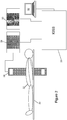
- FIG. 1 illustrates that CT position and orientation is defined by six rigid body parameters, being three translations X, Y , and Z , and three rotations ⁇ x, ⁇ y, and ⁇ z .
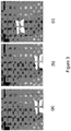
- FIG. 3 (a) to (c) illustrate the procedure, where from an initial position ( Figure 3(a) ) a region of interest is drawn ( Figure 3(b) ) using a GUI, and the chosen 3D CT vertebra surface is then manually translated over the fluoroscopy vertebra ( Figure 3(c) ).
- Embodiments of the invention are intended to address the above problem, by providing a system and method that is able to automatically provide a starting point for the 2D to 3D registration, without relying on human recognition of the features shown in the 2D image.
- This is achieved by pre-processing the 3D data to obtain synthetically generated 2D images of those parts of the 3D data volume which will be used for registration purposes.
- Many different synthetically generated 2D images of the or each part of the 3D volume are produced, each from a different possible viewing direction.
- Each of these synthetic images is then subject to a feature extraction process to extract characterising feature data of the registration feature shown in the images.
- the feature extraction comprises producing an R table for the registration feature.
- the registration feature will be a vertebra, although it will be appreciated that almost any anatomical feature may be used, particularly those which are visible on fluoroscopy images.
- the real-time 2D image obtained for example, via fluoroscopy is processed by applying each of the sets of extracted features thereto, to try and identify which set best matches the registration features in the 2D image.
- the R tables are be applied to the 2D image to obtain respective accumulation images.
- the accumulation images may then be ranked to identify which registration feature is shown in the 2D image, and from which view direction. This gives the required information of which registration feature is being shown in the fluoroscopy image, and also the in-plane location and orientation. This information can then be used as a starting point for the 2D to 3D registration procedure.
- the present invention provides a computer implemented method of determining a start position for a 2D to 3D image registration, the method comprising: a) obtaining characteristic feature sets from a plurality of synthetic 2D images characterising a registration feature imaged therein, the plurality of synthetic 2D images having been previously generated from the 3D image data set, the synthetic 2D images containing the registration feature having been previously imaged according to a plurality of respective viewing parameters; b) obtaining a 2D image to be registered with the 3D image data set; c) applying the characteristic feature sets to the obtained 2D image to locate the registration feature therein; and d) determining which of the one or more characteristic features sets locate the registration feature in the obtained 2D image; wherein at least the viewing parameters relating to the synthetic image corresponding to the determined characteristic feature sets provide information relating to a start position for a subsequent registration of the obtained 2D image to the 3D image data set, wherein the characteristic feature sets are R tables for use with a generalised Hough transform, where
- the information relating to the start position that is obtained is an identification per se of the registration featured (e.g., where vertebrae are used as registrations features, which vertebra is actually being displayed), as well as an in-plane location for the feature in the 2D image, and rotational orientation of the feature (determined from the viewing parameters, which include viewing angle). This then allows the corresponding features in the 3D image data set to be aligned with the 2D image features in accordance with the information, as a starting point for another registration process.
- an identification per se of the registration featured e.g., where vertebrae are used as registrations features, which vertebra is actually being displayed
- an in-plane location for the feature in the 2D image e.g., where vertebrae are used as registrations features, which vertebra is actually being displayed
- rotational orientation of the feature determined from the viewing parameters, which include viewing angle
- the registration feature is a vertebrae.
- different registration features may be used.
- the obtained 2D image is a fluoroscopy image, and hence in such embodiments the registration features may be any feature which can be discerned on a fluoroscopy image.
- any skeletal or hard tissue feature which can be seen and discriminated on a fluoroscopy image may be suitable.
- the 3D image data set is obtained via a computerised tomography (CT) scan, although other 3D scanning techniques may be used to obtain the 3D data set, such as magnetic resonance imaging (MRI), or ultrasound scanning.
- CT computerised tomography
- R-tables and the generalised Hough transform is particularly suitable for identifying known registration features of a shape for which an R-table can be generated in advance.
- the determining comprises ranking the accumulation images to determine which R table best locates the registration feature in the obtained 2D image. More specifically, in one embodiment the ranking comprises finding a normalised maximum pixel value in each accumulation image, and then sorting the accumulation images based on the normalised maximum pixel value to determine the image with the highest normalised intensity value. The image with the highest normalised intensity value is then selected, and the R table which produced that image identified. The DRR from which the identified R table was produced is then further identified, and the viewing parameters which generated the DRR then used as information relating to the start position for a subsequent 2D to 3D registration.
- These N ranked accumulation images are then further processed as follows: A 2D-3D registration similarity measure (for example, gradient difference, Penney, G. P., Weese, J., Little, J. A., Desmedt, P., Hill, D. L. G. and Hawkes, D. J. "A comparison of similarity measures for use in 2D-3D medical image registration", IEEE Trans. Med. Imag., 1998, 17(4), 586-595 ) is used to calculate a similarity value between the 3D image data set (e.g. CT scan) and the obtained 2D image (e.g.
- the accumulation image associated with the maximum value calculated by the similarity measure determines the start position for a subsequent 2D to 3D registration. This enables the normalised maximum intensity pixel values in each of the accumulation images to find a set of likely candidate registration positions, while the more robust and accurate (but more computationally expensive) similarity measure is used to make the final selection of the accumulation image which best locates the registration feature.
- Also disclosed herein is a step for checking that two or more registration features are located in the obtained 2D image.
- two or more registration features are present then it is possible to try to recognise each feature separately, and determine relevant viewing parameters for each. This then allows, for the two or more registration features, to check that the viewing parameters relating to the characteristic feature sets that located the registration features are within a predetermined distance of each other i.e. are similar to each other. If the correct viewing parameters have been obtained for each registration feature then they should be identical or very similar (within a small threshold distance) of each other.
- a start position has been obtained (or at least information relating thereto obtained)
- the registration can be an intensity based operation, as described by the inventors in there prior art paper ibid.
- registration parameters achieved for different registration features are within a predetermined distance.
- different registration features should provide substantially the same registration parameters between the 2D and 3D images, and hence if widely different parameters are obtained from registrations performed on different features then there is a good chance that an error has occurred in at least one of the registrations. Conversely, if the registration parameters are substantially identical then one can be assured that accurate registration has been achieved.
- a confidence value for the registration(s) may be calculated, and displayed to a user. This is particularly advantageous to the clinician, as he or she can be assured that correct registration has been achieved.
- a further aspect of the invention provides an image guided surgical system, comprising: a 2D imaging system arranged in use to obtain a 2D image to be registered with a 3D image data set; and a processor, arranged in use to: a) receive characteristic feature sets from a plurality of synthetic 2D images characterising a registration feature imaged therein, the plurality of synthetic 2D images having been generated from the 3D image data set, the synthetic 2D images containing the registration feature imaged according to a plurality of respective viewing parameters; b) apply the characteristic feature sets to the obtained 2D image to locate the registration feature therein; and c) determine which of the one or more characteristic features sets locate the registration feature in the obtained 2D image; wherein the viewing parameters relating to the synthetic image corresponding to the determined characteristic feature sets provide information relating to a start position for registration of the obtained 2D image to the 3D image data set, wherein the characteristic feature sets are R tables for use with a generalised Hough transform, wherein the applying comprises generating accumulation images by applying the R-tables to
- the embodiment of the invention to be described has two stages.
- the first stage comprises image processing that is performed on a pre-operative 3D image obtained prior to surgery.
- the purpose of the first stage is to obtain characterising feature sets of possible registration features that may be found in the 2D operative image, from several different viewing angles. Once these have been obtained, they may then be used during the second, operative, stage to identify registration features found in the fluoroscopy image, to provide a starting point for registration.
- Figure 9 shows a general purpose computer system 90 having an output display 92 and user input features such as a keyboard 94 to allow control thereof.
- the computer comprises CPU 901, video interface 902 to control the display 92, and input interface 903 to receive user input from keyboard (or other input device) 94.
- data storage medium 904 such as hard disk, solid state storage, or the like, upon which control programs and other data may be stored.
- the data storage medium 904 stored thereon a control program 9048, that retains overall control of the computer 90 during the following procedures described below. Also stored thereon is a feature extraction program 9050 that acts under the control of the control program to extract characterising features of an image. Synthetic image generation program 9052 is also stored, and which is used to generate synthetic images, as described later.
- the input to the synthetic image generation program is 3D data 9042, obtained, for example, from a CT scan or the like.
- the synthetic images that are generated are stored as images 9046, and the extracted features from the images stored as data 9044.
- the extracted features are R-tables 9044.
- An R table 9044 is obtained for each respective synthetic image 9046.
- the registration features that are to be found in the 2D images are vertebrae, and hence the synthetic images generated are images of individual vertebra generated from the 3D CT image thereof.
- the inputs are 1. the preoperative 3D image 9042 (e.g. computed tomography scan) and 2. positions of N vertebrae within the image, which can either be determined manually or using a segmentation algorithm.
- N could be 8 (for example, 5 lumbar vertebrae plus the 3 inferior thoracic vertebrae).
- Step 1A first uses the vertebrae positions to produce N smaller 3D images centred on each vertebrae. That is, a 3D image is obtained of the vertebrae that are to be used as possible registration features.
- Step 1B then takes each of the smaller 3D images and produces a large number of digitally reconstructed radiographs (DRRs), using the synthetic image generation program 9052.
- DRRs are synthetic x-ray images. DRRs will be produced for a wide variety of view directions, simulating the movement and settings on the fluoroscopy set and table to be used in the subsequent operation over a variety of imaging parameters, e.g. view angles, translations, magnification setting, focal length. For example if LAO/RAO angles +- 48 degrees, Cranial caudial angle +- 20 degrees and coronal plane angle +-20 degrees are all sampled at steps of 4 degrees this will result in production of 2904 DRRs per vertebra. Each DRR is stored as a synthetic image 9046.
- DRRs digitally reconstructed radiographs
- a CT volume a number of voxels. If the Hounsfield numbers of these voxels are integrated along the ray and projected onto an imaging plane then the resultant image will resemble a radiograph.
- Another technique to produce DRRs is known as "wobbled splatting", as described by Birkfellner W et al in Wobbled splatting--a fast perspective volume rendering method for simulation of x-ray images from CT Phys Med Biol. 2005 May 7;50(9):N73-84 . Epub 2005 Apr 13. Any known method of producing DRRs may be used in an embodiment of the invention.
- Step 1C then finally takes each of these DRRs and applies the required preparation processes for an image processing technique to allow fast and robust feature extraction of the feature shown within the DRR.
- This is performed by feature extraction program 9050.
- step 1C would produce an R-table for each DRR.
- Figure 6 illustrates the production of an R table from each synthetic image.
- an edge detection algorithm or the like can be used to detect the edge of the vertebra in a synthetic image.
- a point (R) is then chosen within the image, and a number of vectors typically taken from the point to the edge lines to be characterised ( Figure 6(b) ).
- the representation of these vectors then provides the R table ( Figure 6(c) ).
- the R-table files are then stored as feature data sets 9044.
- the feature data set files 9044 from step 1C which will enable fast feature extraction and determination of fluoroscopy view angle are the output from the preoperative image processing workflow, and are then subsequently transferred to the image guided surgical system for using in registration before or during the surgical procedure, as described next.
- Figure 2 shows in schematic form a typical fluoroscopy set and table.
- Operating table 20 is provided with a C-arm 24 on opposite sides of which are an X-ray source and detector.
- the X-ray images from the C-arm are displayed on X-ray display 28.
- the patient lies on the table between the source and detector.
- a computer based image guided surgical system 26 receives the x-ray images on display 28 from the fluoroscopy set and generates the 2D fluoroscopy data augmented with aligned 3D image data, such as a CT scan, as shown on display 30.
- the IGSS 26 is controlled via user input device 32, such as a keyboard or the like.
- Inputs are the intraoperative 2D fluoroscopy or x-ray image, as well as the feature sets 9044, in this case R-tables generated from the synthetic DRR images.
- Step 2A first automatically masks out areas at the edge of the image which contain no (or little) information. These commonly arise due to "coning" of the x-ray beam. Coning is the process of inserting additional filters to reduce radiation exposure to patient and staff.
- the automatic masking operation may be carried out using a combination of thresholding, region growing from image edge seed points and a morphological dilation operator.
- Step 2B then uses the output from step 1C previously i.e. the R-tables to apply a fast and robust feature extraction process to the masked 2D image.
- the input here will be the set of R-tables representing different vertebrae, and different imaging parameters. That is, each R table represents a particular vertebra, as if it were viewed from a different imaging angle defined by the imaging parameters.
- Each of these R-tables will be applied to the image to produce a set of accumulation images equal in size to the number of R-tables.
- An example accumulation image is shown in Figure 8 .
- Step 2C takes the output from step 2B and ranks the view directions in terms of which one is best able to extract each vertebra. For example, if a generalised Hough transform is used in step 1C then step 2C will assess which accumulation image best extracts each vertebra. This may be done by finding a normalised maximum value in the accumulation images for each vertebra.
- One way to find the normalised maximum value of the accumulation images is as follows. Each of the accumulation images are taken in turn. The maximum intensity value V1 of an accumulation image is found. Then the pixel containing the maximum value, and a region within a predetermined number, for example 5, pixels are set to zero. The next highest value is then found within the image, V2, and the pixels within a region of 5 pixels of V2 are set to zero. This process is repeated to calculate the five highest values, V1, V2, V3, V4, and V5. The normalised maximum value then equals V1 divided by (V2+V3+V4+V5)/4.
- Another technique that may be used is to find the pixel that has the maximum value, and then to find the average intensity value of all the pixels in the accumulation image. This average value is then used to normalise the maximum value i.e. the normalised maximum value equals the maximum value divided by the average value.
- the registration feature is best located by the accumulation image with the highest normalised maximum value.
- noisy and low contrast 2D fluoroscopy images can result in the assessment of the registration feature's position being inaccurate. Therefore, it is desirable that another process of ranking the accumulation images be applied in order to improve the accuracy of step 2C.
- N ranked accumulation images may then be further processed as follows: A 2D-3D registration similarity measure (for example, gradient difference, Penney, G. P., Weese, J., Little, J. A., Desmedt, P., Hill, D. L. G. and Hawkes, D. J. "A comparison of similarity measures for use in 2D-3D medical image registration", IEEE Trans. Med. Imag., 1998, 17(4), 586-595 ) is used to calculate a similarity value between the 3D image data (e.g. CT scan) and the 2D image (e.g. fluoroscopy image) for each of the first N accumulation images found.
- the accumulation image associated with the maximum value calculated by the similarity measure determines the start position for a subsequent 2D to 3D registration.
- the overall effect of this processing is that the normalised maximum intensity is first used to find a small number of accumulation images which may provide the starting position for 2D-3D registration, and then the more accurate and robust (but computationally more expensive) similarity measure is used to make the final selection, thus accurately determining which accumulation image best extracts each vertebra.
- Step 2D checks for each vertebra whether it has been successfully extracted by step 2C. This is achieved by comparing the view directions for each vertebra determined by step 2C. If two or more vertebrae have been successfully extracted then "similar" views will be obtained. A suitable threshold for "similar" views, for example could be whether they are within five degrees for each rotation parameter. Due to the large search space used, if feature extraction on each vertebra is independent then similar positions are unlikely to occur by chance. Note not all vertebrae will appear in a fluoroscopy image and so this stage determines which vertebra are within the fluoroscopy image, as well as which vertebra have been accurately extracted. If only one or fewer vertebrae are extracted then the algorithm stops.
- Step 2E then takes the vertebrae which have been successfully extracted and uses knowledge of their view directions and in-plane position of where the feature was located (as determined by step 2C) to automatically provide a starting estimate for an intensity based 2D-3D registration as described in Penney et al. IPCAI 2011, referenced above. At this stage therefore, actual registration is performed, using the prior art intensity based method described in the above reference.
- Step 2F is a check for registration success. For example, the final registration positions for each vertebra used in step 2E are compared. Successful registrations to different vertebra should produce very similar final positions. These will be compared using a suitable threshold, for example whether rotation parameters are within 2 degrees and in-plane translations within 2 mm. If no successful registrations are found then the algorithm ceases operation.
- Step 2G calculates a confidence value for the registration. For example this value could be calculated using the relative vertebrae positional information calculated in step 2F and/or using the final value of the registration similarity value.
- a confidence value may be calculated using statistics from previous manually checked registrations as follows:
- step 2H displays the requested information to the clinician along with the confidence value.
- this could be an overlay of the vasculature from the 3D preoperative image onto the interventional 2D fluoroscopy image.
- a starting position for an intensity based 2D to 3D image registration is found by comparing feature sets from synthetic images generated from a large amount of possible viewing angles with the live 2D data, and finding which of the feature sets best matches the view shown in the 2D image.
- the viewing parameters that were used to generate the synthetic image the feature set of which best matched the 2D data, as well as the translational positioning data that is obtained from the matching process are then used to provide an automatic starting position for the intensity based image registration process.
- the use of the automated technique also allows for the calculation of a confidence value in the registration, which can be displayed to the surgeon and hence provide the surgeon or other clinician with confidence that proper registration has being achieved.
- replacing the prior art manual technique with embodiments of the present invention removes one of the sources of error in an image guided surgical procedure.
Landscapes
- Engineering & Computer Science (AREA)
- Health & Medical Sciences (AREA)
- Life Sciences & Earth Sciences (AREA)
- Medical Informatics (AREA)
- Computer Vision & Pattern Recognition (AREA)
- Physics & Mathematics (AREA)
- General Health & Medical Sciences (AREA)
- Nuclear Medicine, Radiotherapy & Molecular Imaging (AREA)
- Radiology & Medical Imaging (AREA)
- General Physics & Mathematics (AREA)
- Theoretical Computer Science (AREA)
- Biophysics (AREA)
- Molecular Biology (AREA)
- High Energy & Nuclear Physics (AREA)
- Optics & Photonics (AREA)
- Pathology (AREA)
- Biomedical Technology (AREA)
- Heart & Thoracic Surgery (AREA)
- Veterinary Medicine (AREA)
- Surgery (AREA)
- Animal Behavior & Ethology (AREA)
- Public Health (AREA)
- Quality & Reliability (AREA)
- Apparatus For Radiation Diagnosis (AREA)
- Image Analysis (AREA)
- Image Processing (AREA)
Claims (9)
- Computerimplementiertes Verfahren zum Bestimmen einer Startposition für eine 2D-zu-3D-Bildregistrierung, wobei das Verfahren die folgenden Schritte in dieser Reihenfolge umfasst:a) Erlangen charakteristischer Merkmalsätze, die ein Registrierungsmerkmal charakterisieren, das in einer Vielzahl von synthetischen 2D-Bildern abgebildet ist, wobei die Vielzahl von synthetischen 2D-Bildern aus einem 3D-Bilddatensatz generiert wurde und die synthetischen 2D-Bilder das Registrierungsmerkmal enthalten, das gemäß einer Vielzahl von entsprechenden Beobachtungsparametern abgebildet wurde;b) Erlangen eines 2D-Bilds, das mit dem 3D-Bilddatensatz registriert werden soll;c) Anwenden des charakteristischen Merkmalsatzes an das erlangte 2D-Bild, um das Registrierungsmerkmal darin zu lokalisieren; undd) Bestimmen, welches des einen oder der mehreren charakteristischen Merkmalsätze das Registrierungsmerkmal in dem erlangten 2D-Bild lokalisiert;wobei mindestens die Beobachtungsparameter, die sich auf das synthetische Bild beziehen, das den bestimmten charakteristischen Merkmalsätzen entspricht, Informationen bereitstellen, die sich auf eine Startposition für eine nachfolgende Registrierung des erlangten 2D-Bildes zu dem 3D-Bilddatensatz beziehen,
wobei die charakteristischen Merkmalsätze R-Tabellen zur Verwendung mit einer generalisierten Hough-Transformation sind,
wobei das Anwenden das Generieren von Akkumulationsbildern durch Anwenden der R-Tabellen an dem erlangten 2D-Bild unter Verwendung der generalisierten Hough-Transformation umfasst. - Verfahren nach Anspruch 1, wobei das Registrierungsmerkmal ein Wirbel ist.
- Verfahren nach einem der vorstehenden Ansprüche, wobei das erlangte 2D-Bild ein Fluoroskopie-Bild ist.
- Verfahren nach einem der vorstehenden Ansprüche, wobei der 3D-Bilddatensatz über einen Computertomographie-(CT-)Scan erlangt wird.
- Verfahren nach Anspruch 1, wobei das Bestimmen das Einstufen der Akkumulationsbilder umfasst, um zu bestimmen, welche R-Tabelle das Registrierungsmerkmal in dem erlangten 2D-Bild am besten lokalisiert, und wobei die ersten N eingestuften Akkumulationsbilder weiter verarbeitet werden, wobei das weitere Verarbeiten Folgendes umfasst:a) Berechnen eines Ähnlichkeitswerts zwischen dem 3D-Datensatz und dem erlangten 2D-Bild für jedes der N eingestuften Akkumulationsbilder durch Mittel einer 2D-3D-Registrierungsähnlichkeitsmessung; undb) Bestimmen der Startposition für eine nachfolgende 2D-zu-3D-Registrierung auf Grundlage des Akkumulationsbilds, das mit dem maximalen berechneten Ähnlichkeitswert assoziiert ist.
- Verfahren nach einem der vorstehenden Ansprüche, ferner das Prüfen umfassend, dass zwei oder mehr Registrierungsmerkmale in dem erlangten 2D-Bild lokalisiert sind.
- Verfahren nach einem der vorstehenden Ansprüche, ferner das Durchführen der 2D-zu-3D-Bildregistrierung unter Verwendung der bestimmten Startpositionsinformationen umfassend.
- Verfahren nach Anspruch 6 oder 7, ferner das Berechnen eines Konfidenzwerts für die Registrierung(en) und das Anzeigen des Konfidenzwerts für einen Benutzer umfassend.
- Bildgeführtes chirurgisches System, Folgendes umfassend:ein 2D-Abbildungssystem (24), das angeordnet ist, um ein 2D-Bild zu erlangen (28), das mit einem 3D-Datensatz (9042) registriert werden soll;und einen Prozessor (90), der bei Verwendung angeordnet ist, die Schritte des Verfahrens nach Anspruch 1 auszuführen.
Priority Applications (1)
| Application Number | Priority Date | Filing Date | Title |
|---|---|---|---|
| EP19174492.9A EP3543953A1 (de) | 2012-03-05 | 2013-03-01 | Verfahren und system zur unterstützung von 2d-3d-bildregistrierung |
Applications Claiming Priority (2)
| Application Number | Priority Date | Filing Date | Title |
|---|---|---|---|
| GBGB1203883.2A GB201203883D0 (en) | 2012-03-05 | 2012-03-05 | Method and system to assist 2D-3D image registration |
| PCT/GB2013/050515 WO2013132235A1 (en) | 2012-03-05 | 2013-03-01 | Method and system to assist 2d-3d image registration |
Related Child Applications (1)
| Application Number | Title | Priority Date | Filing Date |
|---|---|---|---|
| EP19174492.9A Division EP3543953A1 (de) | 2012-03-05 | 2013-03-01 | Verfahren und system zur unterstützung von 2d-3d-bildregistrierung |
Publications (2)
| Publication Number | Publication Date |
|---|---|
| EP2823463A1 EP2823463A1 (de) | 2015-01-14 |
| EP2823463B1 true EP2823463B1 (de) | 2019-05-22 |
Family
ID=46003168
Family Applications (2)
| Application Number | Title | Priority Date | Filing Date |
|---|---|---|---|
| EP13709509.7A Active EP2823463B1 (de) | 2012-03-05 | 2013-03-01 | Verfahren und system zur unterstützung von 2d-3d-bildregistrierung |
| EP19174492.9A Withdrawn EP3543953A1 (de) | 2012-03-05 | 2013-03-01 | Verfahren und system zur unterstützung von 2d-3d-bildregistrierung |
Family Applications After (1)
| Application Number | Title | Priority Date | Filing Date |
|---|---|---|---|
| EP19174492.9A Withdrawn EP3543953A1 (de) | 2012-03-05 | 2013-03-01 | Verfahren und system zur unterstützung von 2d-3d-bildregistrierung |
Country Status (6)
| Country | Link |
|---|---|
| US (1) | US9240046B2 (de) |
| EP (2) | EP2823463B1 (de) |
| JP (1) | JP6215851B2 (de) |
| CN (1) | CN104254874B (de) |
| GB (1) | GB201203883D0 (de) |
| WO (1) | WO2013132235A1 (de) |
Cited By (1)
| Publication number | Priority date | Publication date | Assignee | Title |
|---|---|---|---|---|
| US11580690B1 (en) | 2021-08-31 | 2023-02-14 | Raytheon Company | Horizon-based navigation |
Families Citing this family (35)
| Publication number | Priority date | Publication date | Assignee | Title |
|---|---|---|---|---|
| US10405821B2 (en) | 2014-06-06 | 2019-09-10 | Koninklijke Philips N.V. | Imaging system for a vertebral level |
| CN104268918B (zh) * | 2014-10-09 | 2015-06-10 | 佛山精鹰传媒股份有限公司 | 一种二维动画与三维立体动画融合的处理方法 |
| GB2536650A (en) | 2015-03-24 | 2016-09-28 | Augmedics Ltd | Method and system for combining video-based and optic-based augmented reality in a near eye display |
| CN105093552B (zh) * | 2015-09-17 | 2017-08-25 | 清华大学深圳研究生院 | 立体透视方法及系统 |
| JP6632361B2 (ja) * | 2015-12-15 | 2020-01-22 | キヤノン株式会社 | 画像処理装置、画像処理システム、画像処理方法、及びプログラム。 |
| US10368956B2 (en) * | 2016-02-16 | 2019-08-06 | The Johns Hopkins University | MR-levelcheck-2: method for localization of structures in projection images |
| EP3988027B1 (de) | 2016-03-13 | 2024-05-01 | Vuze Medical Ltd. | Vorrichtung zur verwendung mit skelettprozeduren |
| WO2019012520A1 (en) * | 2017-07-08 | 2019-01-17 | Vuze Medical Ltd. | APPARATUS AND METHODS FOR USE WITH IMAGE-GUIDED SKELETAL PROCEDURES |
| WO2018067794A1 (en) | 2016-10-05 | 2018-04-12 | Nuvasive, Inc. | Surgical navigation system and related methods |
| US11065069B2 (en) | 2017-05-10 | 2021-07-20 | Mako Surgical Corp. | Robotic spine surgery system and methods |
| US11033341B2 (en) | 2017-05-10 | 2021-06-15 | Mako Surgical Corp. | Robotic spine surgery system and methods |
| US10210631B1 (en) | 2017-08-18 | 2019-02-19 | Synapse Technology Corporation | Generating synthetic image data |
| US12458411B2 (en) | 2017-12-07 | 2025-11-04 | Augmedics Ltd. | Spinous process clamp |
| US12521201B2 (en) | 2017-12-07 | 2026-01-13 | Augmedics Ltd. | Spinous process clamp |
| EP3787543A4 (de) | 2018-05-02 | 2022-01-19 | Augmedics Ltd. | Registrierung einer bezugsmarke für ein system der erweiterten realität |
| US11504548B2 (en) | 2018-08-02 | 2022-11-22 | Mayo Foundation For Medical Education And Research | Systems and methods for quality control in image-guided radiotherapy |
| US11766296B2 (en) | 2018-11-26 | 2023-09-26 | Augmedics Ltd. | Tracking system for image-guided surgery |
| CN110148160A (zh) * | 2019-05-22 | 2019-08-20 | 合肥中科离子医学技术装备有限公司 | 一种正交x射线影像快速2d-3d医学图像配准方法 |
| US12178666B2 (en) | 2019-07-29 | 2024-12-31 | Augmedics Ltd. | Fiducial marker |
| US11980506B2 (en) | 2019-07-29 | 2024-05-14 | Augmedics Ltd. | Fiducial marker |
| US11382712B2 (en) | 2019-12-22 | 2022-07-12 | Augmedics Ltd. | Mirroring in image guided surgery |
| US12367597B2 (en) | 2020-01-15 | 2025-07-22 | Rensselaer Polytechnic Institute | Trackerless 2D ultrasound frame to 3D image volume registration |
| CN115361920A (zh) | 2020-03-27 | 2022-11-18 | 马科外科公司 | 具有触觉接口的机器人脊柱外科手术系统和方法 |
| US11389252B2 (en) | 2020-06-15 | 2022-07-19 | Augmedics Ltd. | Rotating marker for image guided surgery |
| US12502163B2 (en) | 2020-09-09 | 2025-12-23 | Augmedics Ltd. | Universal tool adapter for image-guided surgery |
| US12239385B2 (en) | 2020-09-09 | 2025-03-04 | Augmedics Ltd. | Universal tool adapter |
| JP2023553420A (ja) * | 2020-12-02 | 2023-12-21 | アクルー イメージング,インコーポレイテッド | マルチモーダル画像を蛍光透視像に融合する方法および装置 |
| CN112614169B (zh) * | 2020-12-24 | 2022-03-25 | 电子科技大学 | 基于深度学习网络的2d/3d脊椎ct层级配准方法 |
| CN113822845B (zh) * | 2021-05-31 | 2025-11-04 | 腾讯科技(深圳)有限公司 | 医学图像中组织结构的层级分割方法、装置、设备及介质 |
| US12150821B2 (en) | 2021-07-29 | 2024-11-26 | Augmedics Ltd. | Rotating marker and adapter for image-guided surgery |
| US12475662B2 (en) | 2021-08-18 | 2025-11-18 | Augmedics Ltd. | Stereoscopic display and digital loupe for augmented-reality near-eye display |
| WO2023203521A1 (en) | 2022-04-21 | 2023-10-26 | Augmedics Ltd. | Systems and methods for medical image visualization |
| JP2025531829A (ja) | 2022-09-13 | 2025-09-25 | オーグメディックス リミテッド | 画像誘導医療介入のための拡張現実アイウェア |
| CN116327228B (zh) * | 2023-03-30 | 2024-04-30 | 杭州邦杰星医疗科技有限公司 | 一种2d-3d图像初始值计算的方法 |
| CN117237426B (zh) * | 2023-09-18 | 2024-03-22 | 北京大学第三医院(北京大学第三临床医学院) | 一种基于腰椎双斜位x光片的椎骨配准方法 |
Family Cites Families (16)
| Publication number | Priority date | Publication date | Assignee | Title |
|---|---|---|---|---|
| JP3878259B2 (ja) * | 1996-11-13 | 2007-02-07 | 東芝医用システムエンジニアリング株式会社 | 医用画像処理装置 |
| US6556713B2 (en) * | 1997-07-31 | 2003-04-29 | Canon Kabushiki Kaisha | Image processing apparatus and method and storage medium |
| JPH11220628A (ja) * | 1998-01-30 | 1999-08-10 | Canon Inc | 画像処理装置及び方法並びに記憶媒体 |
| JP4338155B2 (ja) * | 1998-06-12 | 2009-10-07 | キヤノン株式会社 | 画像処理装置及びその方法、コンピュータ可読メモリ |
| JP2000163558A (ja) * | 1998-11-27 | 2000-06-16 | Mitsubishi Electric Corp | 位置合わせ装置 |
| US6972865B1 (en) * | 1999-03-01 | 2005-12-06 | Canon Kabushiki Kaisha | Image processing apparatus and method, and storage medium |
| JP4104054B2 (ja) * | 2001-08-27 | 2008-06-18 | 富士フイルム株式会社 | 画像の位置合わせ装置および画像処理装置 |
| JP2003109017A (ja) * | 2001-09-28 | 2003-04-11 | Hitachi Ltd | 輪郭形状の欠陥検査方法及び装置 |
| US7492931B2 (en) * | 2003-11-26 | 2009-02-17 | Ge Medical Systems Global Technology Company, Llc | Image temporal change detection and display method and apparatus |
| US8515527B2 (en) * | 2004-10-13 | 2013-08-20 | General Electric Company | Method and apparatus for registering 3D models of anatomical regions of a heart and a tracking system with projection images of an interventional fluoroscopic system |
| US7889905B2 (en) * | 2005-05-23 | 2011-02-15 | The Penn State Research Foundation | Fast 3D-2D image registration method with application to continuously guided endoscopy |
| US20080037843A1 (en) * | 2006-08-11 | 2008-02-14 | Accuray Incorporated | Image segmentation for DRR generation and image registration |
| EP2111604A2 (de) | 2006-12-22 | 2009-10-28 | Koninklijke Philips Electronics N.V. | Bildgebungssystem und bildgebungsverfahren zur abbildung eines objekts |
| RU2568635C2 (ru) * | 2007-12-18 | 2015-11-20 | Конинклейке Филипс Электроникс, Н.В. | Регистрация двумерных/трехмерных изображений на основе признаков |
| CN101983035B (zh) * | 2008-04-03 | 2013-02-13 | 皇家飞利浦电子股份有限公司 | 呼吸确定装置 |
| US8819591B2 (en) * | 2009-10-30 | 2014-08-26 | Accuray Incorporated | Treatment planning in a virtual environment |
-
2012
- 2012-03-05 GB GBGB1203883.2A patent/GB201203883D0/en not_active Ceased
-
2013
- 2013-03-01 CN CN201380022492.8A patent/CN104254874B/zh active Active
- 2013-03-01 JP JP2014560439A patent/JP6215851B2/ja active Active
- 2013-03-01 EP EP13709509.7A patent/EP2823463B1/de active Active
- 2013-03-01 WO PCT/GB2013/050515 patent/WO2013132235A1/en not_active Ceased
- 2013-03-01 US US14/382,999 patent/US9240046B2/en active Active
- 2013-03-01 EP EP19174492.9A patent/EP3543953A1/de not_active Withdrawn
Non-Patent Citations (1)
| Title |
|---|
| HELEN HONG ET AL: "Fast 2D-3D Point-Based Registration Using GPU-Based Preprocessing for Image-Guided Surgery", 1 January 2006, PROGRESS IN PATTERN RECOGNITION, IMAGE ANALYSIS AND APPLICATIONS LECTURE NOTES IN COMPUTER SCIENCE;;LNCS, SPRINGER, BERLIN, DE, PAGE(S) 218 - 226, ISBN: 978-3-540-46556-0, XP019045813 * |
Cited By (1)
| Publication number | Priority date | Publication date | Assignee | Title |
|---|---|---|---|---|
| US11580690B1 (en) | 2021-08-31 | 2023-02-14 | Raytheon Company | Horizon-based navigation |
Also Published As
| Publication number | Publication date |
|---|---|
| JP6215851B2 (ja) | 2017-10-18 |
| GB201203883D0 (en) | 2012-04-18 |
| EP3543953A1 (de) | 2019-09-25 |
| US20150043798A1 (en) | 2015-02-12 |
| CN104254874A (zh) | 2014-12-31 |
| EP2823463A1 (de) | 2015-01-14 |
| JP2015518383A (ja) | 2015-07-02 |
| CN104254874B (zh) | 2017-08-08 |
| WO2013132235A1 (en) | 2013-09-12 |
| US9240046B2 (en) | 2016-01-19 |
Similar Documents
| Publication | Publication Date | Title |
|---|---|---|
| EP2823463B1 (de) | Verfahren und system zur unterstützung von 2d-3d-bildregistrierung | |
| Weese et al. | Voxel-based 2-D/3-D registration of fluoroscopy images and CT scans for image-guided surgery | |
| Penney et al. | A comparison of similarity measures for use in 2-D-3-D medical image registration | |
| US10977812B2 (en) | Deformation correction | |
| Penney et al. | Validation of a two‐to three‐dimensional registration algorithm for aligning preoperative CT images and intraoperative fluoroscopy images | |
| US10650513B2 (en) | Method and system for tomosynthesis imaging | |
| CN103379861B (zh) | 用于在血管介入程序中提供支持介入设备的准确定位的图像表示的医学成像设备 | |
| EP2849630B1 (de) | Virtuelle bezugsmarkierungen | |
| CN120641945A (zh) | 用于处理解剖成像数据的计算机实施的方法、设备、系统和计算机程序产品 | |
| Tomazevic et al. | 3-D/2-D registration by integrating 2-D information in 3-D | |
| US20050004454A1 (en) | Method for marker-free automatic fusion of 2-D fluoroscopic C-arm images with preoperative 3D images using an intraoperatively obtained 3D data record | |
| US20130070995A1 (en) | 2d/3d image registration method | |
| Varnavas et al. | Increasing the automation of a 2D-3D registration system | |
| Penney | Registration of tomographic images to X-ray projections for use in image guided interventions | |
| Nicolau et al. | A complete augmented reality guidance system for liver punctures: First clinical evaluation | |
| Schaffert et al. | Robust multi-view 2-d/3-d registration using point-to-plane correspondence model | |
| CN109155068B (zh) | 组合式x射线/相机介入中的运动补偿 | |
| Firle et al. | Mutual-information-based registration for ultrasound and CT datasets | |
| Zheng et al. | Reality-augmented virtual fluoroscopy for computer-assisted diaphyseal long bone fracture osteosynthesis: a novel technique and feasibility study results | |
| EP4567731A1 (de) | Verfahren zur verarbeitung medizinischer bilddaten eines patientenkörpers | |
| Cao et al. | An improved multi-resolution 2D/3D registration method | |
| CN119053992A (zh) | 用于辅助将工具相对于患者的特定身体部位进行定位的方法、计算设备、系统和计算机程序产品 | |
| CN121504735A (zh) | 应用于血管介入手术的图像生成方法及设备 | |
| Gamage et al. | Computer assisted 3D pre-operative planning tool for femur fracture orthopedic surgery | |
| CN121504734A (zh) | 应用于血管介入手术的图像融合方法及设备 |
Legal Events
| Date | Code | Title | Description |
|---|---|---|---|
| PUAI | Public reference made under article 153(3) epc to a published international application that has entered the european phase |
Free format text: ORIGINAL CODE: 0009012 |
|
| 17P | Request for examination filed |
Effective date: 20140827 |
|
| AK | Designated contracting states |
Kind code of ref document: A1 Designated state(s): AL AT BE BG CH CY CZ DE DK EE ES FI FR GB GR HR HU IE IS IT LI LT LU LV MC MK MT NL NO PL PT RO RS SE SI SK SM TR |
|
| AX | Request for extension of the european patent |
Extension state: BA ME |
|
| DAX | Request for extension of the european patent (deleted) | ||
| RAP1 | Party data changed (applicant data changed or rights of an application transferred) |
Owner name: CYDAR LIMITED |
|
| 17Q | First examination report despatched |
Effective date: 20160727 |
|
| STAA | Information on the status of an ep patent application or granted ep patent |
Free format text: STATUS: EXAMINATION IS IN PROGRESS |
|
| GRAP | Despatch of communication of intention to grant a patent |
Free format text: ORIGINAL CODE: EPIDOSNIGR1 |
|
| STAA | Information on the status of an ep patent application or granted ep patent |
Free format text: STATUS: GRANT OF PATENT IS INTENDED |
|
| INTG | Intention to grant announced |
Effective date: 20190109 |
|
| GRAS | Grant fee paid |
Free format text: ORIGINAL CODE: EPIDOSNIGR3 |
|
| GRAA | (expected) grant |
Free format text: ORIGINAL CODE: 0009210 |
|
| STAA | Information on the status of an ep patent application or granted ep patent |
Free format text: STATUS: THE PATENT HAS BEEN GRANTED |
|
| AK | Designated contracting states |
Kind code of ref document: B1 Designated state(s): AL AT BE BG CH CY CZ DE DK EE ES FI FR GB GR HR HU IE IS IT LI LT LU LV MC MK MT NL NO PL PT RO RS SE SI SK SM TR |
|
| REG | Reference to a national code |
Ref country code: GB Ref legal event code: FG4D |
|
| REG | Reference to a national code |
Ref country code: CH Ref legal event code: EP |
|
| REG | Reference to a national code |
Ref country code: IE Ref legal event code: FG4D |
|
| REG | Reference to a national code |
Ref country code: DE Ref legal event code: R096 Ref document number: 602013055712 Country of ref document: DE |
|
| REG | Reference to a national code |
Ref country code: AT Ref legal event code: REF Ref document number: 1136995 Country of ref document: AT Kind code of ref document: T Effective date: 20190615 |
|
| REG | Reference to a national code |
Ref country code: NL Ref legal event code: FP |
|
| REG | Reference to a national code |
Ref country code: LT Ref legal event code: MG4D |
|
| PG25 | Lapsed in a contracting state [announced via postgrant information from national office to epo] |
Ref country code: ES Free format text: LAPSE BECAUSE OF FAILURE TO SUBMIT A TRANSLATION OF THE DESCRIPTION OR TO PAY THE FEE WITHIN THE PRESCRIBED TIME-LIMIT Effective date: 20190522 Ref country code: LT Free format text: LAPSE BECAUSE OF FAILURE TO SUBMIT A TRANSLATION OF THE DESCRIPTION OR TO PAY THE FEE WITHIN THE PRESCRIBED TIME-LIMIT Effective date: 20190522 Ref country code: SE Free format text: LAPSE BECAUSE OF FAILURE TO SUBMIT A TRANSLATION OF THE DESCRIPTION OR TO PAY THE FEE WITHIN THE PRESCRIBED TIME-LIMIT Effective date: 20190522 Ref country code: HR Free format text: LAPSE BECAUSE OF FAILURE TO SUBMIT A TRANSLATION OF THE DESCRIPTION OR TO PAY THE FEE WITHIN THE PRESCRIBED TIME-LIMIT Effective date: 20190522 Ref country code: AL Free format text: LAPSE BECAUSE OF FAILURE TO SUBMIT A TRANSLATION OF THE DESCRIPTION OR TO PAY THE FEE WITHIN THE PRESCRIBED TIME-LIMIT Effective date: 20190522 Ref country code: NO Free format text: LAPSE BECAUSE OF FAILURE TO SUBMIT A TRANSLATION OF THE DESCRIPTION OR TO PAY THE FEE WITHIN THE PRESCRIBED TIME-LIMIT Effective date: 20190822 Ref country code: FI Free format text: LAPSE BECAUSE OF FAILURE TO SUBMIT A TRANSLATION OF THE DESCRIPTION OR TO PAY THE FEE WITHIN THE PRESCRIBED TIME-LIMIT Effective date: 20190522 Ref country code: PT Free format text: LAPSE BECAUSE OF FAILURE TO SUBMIT A TRANSLATION OF THE DESCRIPTION OR TO PAY THE FEE WITHIN THE PRESCRIBED TIME-LIMIT Effective date: 20190922 |
|
| PG25 | Lapsed in a contracting state [announced via postgrant information from national office to epo] |
Ref country code: LV Free format text: LAPSE BECAUSE OF FAILURE TO SUBMIT A TRANSLATION OF THE DESCRIPTION OR TO PAY THE FEE WITHIN THE PRESCRIBED TIME-LIMIT Effective date: 20190522 Ref country code: GR Free format text: LAPSE BECAUSE OF FAILURE TO SUBMIT A TRANSLATION OF THE DESCRIPTION OR TO PAY THE FEE WITHIN THE PRESCRIBED TIME-LIMIT Effective date: 20190823 Ref country code: BG Free format text: LAPSE BECAUSE OF FAILURE TO SUBMIT A TRANSLATION OF THE DESCRIPTION OR TO PAY THE FEE WITHIN THE PRESCRIBED TIME-LIMIT Effective date: 20190822 Ref country code: RS Free format text: LAPSE BECAUSE OF FAILURE TO SUBMIT A TRANSLATION OF THE DESCRIPTION OR TO PAY THE FEE WITHIN THE PRESCRIBED TIME-LIMIT Effective date: 20190522 |
|
| REG | Reference to a national code |
Ref country code: AT Ref legal event code: MK05 Ref document number: 1136995 Country of ref document: AT Kind code of ref document: T Effective date: 20190522 |
|
| PG25 | Lapsed in a contracting state [announced via postgrant information from national office to epo] |
Ref country code: CZ Free format text: LAPSE BECAUSE OF FAILURE TO SUBMIT A TRANSLATION OF THE DESCRIPTION OR TO PAY THE FEE WITHIN THE PRESCRIBED TIME-LIMIT Effective date: 20190522 Ref country code: RO Free format text: LAPSE BECAUSE OF FAILURE TO SUBMIT A TRANSLATION OF THE DESCRIPTION OR TO PAY THE FEE WITHIN THE PRESCRIBED TIME-LIMIT Effective date: 20190522 Ref country code: SK Free format text: LAPSE BECAUSE OF FAILURE TO SUBMIT A TRANSLATION OF THE DESCRIPTION OR TO PAY THE FEE WITHIN THE PRESCRIBED TIME-LIMIT Effective date: 20190522 Ref country code: EE Free format text: LAPSE BECAUSE OF FAILURE TO SUBMIT A TRANSLATION OF THE DESCRIPTION OR TO PAY THE FEE WITHIN THE PRESCRIBED TIME-LIMIT Effective date: 20190522 Ref country code: AT Free format text: LAPSE BECAUSE OF FAILURE TO SUBMIT A TRANSLATION OF THE DESCRIPTION OR TO PAY THE FEE WITHIN THE PRESCRIBED TIME-LIMIT Effective date: 20190522 Ref country code: DK Free format text: LAPSE BECAUSE OF FAILURE TO SUBMIT A TRANSLATION OF THE DESCRIPTION OR TO PAY THE FEE WITHIN THE PRESCRIBED TIME-LIMIT Effective date: 20190522 |
|
| REG | Reference to a national code |
Ref country code: DE Ref legal event code: R097 Ref document number: 602013055712 Country of ref document: DE |
|
| PG25 | Lapsed in a contracting state [announced via postgrant information from national office to epo] |
Ref country code: IT Free format text: LAPSE BECAUSE OF FAILURE TO SUBMIT A TRANSLATION OF THE DESCRIPTION OR TO PAY THE FEE WITHIN THE PRESCRIBED TIME-LIMIT Effective date: 20190522 Ref country code: SM Free format text: LAPSE BECAUSE OF FAILURE TO SUBMIT A TRANSLATION OF THE DESCRIPTION OR TO PAY THE FEE WITHIN THE PRESCRIBED TIME-LIMIT Effective date: 20190522 |
|
| PLBE | No opposition filed within time limit |
Free format text: ORIGINAL CODE: 0009261 |
|
| STAA | Information on the status of an ep patent application or granted ep patent |
Free format text: STATUS: NO OPPOSITION FILED WITHIN TIME LIMIT |
|
| PG25 | Lapsed in a contracting state [announced via postgrant information from national office to epo] |
Ref country code: TR Free format text: LAPSE BECAUSE OF FAILURE TO SUBMIT A TRANSLATION OF THE DESCRIPTION OR TO PAY THE FEE WITHIN THE PRESCRIBED TIME-LIMIT Effective date: 20190522 |
|
| 26N | No opposition filed |
Effective date: 20200225 |
|
| PG25 | Lapsed in a contracting state [announced via postgrant information from national office to epo] |
Ref country code: PL Free format text: LAPSE BECAUSE OF FAILURE TO SUBMIT A TRANSLATION OF THE DESCRIPTION OR TO PAY THE FEE WITHIN THE PRESCRIBED TIME-LIMIT Effective date: 20190522 |
|
| PG25 | Lapsed in a contracting state [announced via postgrant information from national office to epo] |
Ref country code: SI Free format text: LAPSE BECAUSE OF FAILURE TO SUBMIT A TRANSLATION OF THE DESCRIPTION OR TO PAY THE FEE WITHIN THE PRESCRIBED TIME-LIMIT Effective date: 20190522 |
|
| PG25 | Lapsed in a contracting state [announced via postgrant information from national office to epo] |
Ref country code: MC Free format text: LAPSE BECAUSE OF FAILURE TO SUBMIT A TRANSLATION OF THE DESCRIPTION OR TO PAY THE FEE WITHIN THE PRESCRIBED TIME-LIMIT Effective date: 20190522 |
|
| REG | Reference to a national code |
Ref country code: CH Ref legal event code: PL |
|
| REG | Reference to a national code |
Ref country code: BE Ref legal event code: MM Effective date: 20200331 |
|
| PG25 | Lapsed in a contracting state [announced via postgrant information from national office to epo] |
Ref country code: LU Free format text: LAPSE BECAUSE OF NON-PAYMENT OF DUE FEES Effective date: 20200301 |
|
| PG25 | Lapsed in a contracting state [announced via postgrant information from national office to epo] |
Ref country code: LI Free format text: LAPSE BECAUSE OF NON-PAYMENT OF DUE FEES Effective date: 20200331 Ref country code: CH Free format text: LAPSE BECAUSE OF NON-PAYMENT OF DUE FEES Effective date: 20200331 |
|
| PG25 | Lapsed in a contracting state [announced via postgrant information from national office to epo] |
Ref country code: BE Free format text: LAPSE BECAUSE OF NON-PAYMENT OF DUE FEES Effective date: 20200331 |
|
| PG25 | Lapsed in a contracting state [announced via postgrant information from national office to epo] |
Ref country code: MT Free format text: LAPSE BECAUSE OF FAILURE TO SUBMIT A TRANSLATION OF THE DESCRIPTION OR TO PAY THE FEE WITHIN THE PRESCRIBED TIME-LIMIT Effective date: 20190522 Ref country code: CY Free format text: LAPSE BECAUSE OF FAILURE TO SUBMIT A TRANSLATION OF THE DESCRIPTION OR TO PAY THE FEE WITHIN THE PRESCRIBED TIME-LIMIT Effective date: 20190522 |
|
| PG25 | Lapsed in a contracting state [announced via postgrant information from national office to epo] |
Ref country code: MK Free format text: LAPSE BECAUSE OF FAILURE TO SUBMIT A TRANSLATION OF THE DESCRIPTION OR TO PAY THE FEE WITHIN THE PRESCRIBED TIME-LIMIT Effective date: 20190522 Ref country code: IS Free format text: LAPSE BECAUSE OF FAILURE TO SUBMIT A TRANSLATION OF THE DESCRIPTION OR TO PAY THE FEE WITHIN THE PRESCRIBED TIME-LIMIT Effective date: 20190922 |
|
| P01 | Opt-out of the competence of the unified patent court (upc) registered |
Effective date: 20230321 |
|
| PGFP | Annual fee paid to national office [announced via postgrant information from national office to epo] |
Ref country code: DE Payment date: 20250321 Year of fee payment: 13 |
|
| PGFP | Annual fee paid to national office [announced via postgrant information from national office to epo] |
Ref country code: NL Payment date: 20250303 Year of fee payment: 13 |
|
| PGFP | Annual fee paid to national office [announced via postgrant information from national office to epo] |
Ref country code: IE Payment date: 20250226 Year of fee payment: 13 |
|
| PGFP | Annual fee paid to national office [announced via postgrant information from national office to epo] |
Ref country code: FR Payment date: 20250307 Year of fee payment: 13 |
|
| PGFP | Annual fee paid to national office [announced via postgrant information from national office to epo] |
Ref country code: GB Payment date: 20250226 Year of fee payment: 13 |