EP2823339B1 - Dispositif de localisation pour l'evaluation de la distance entre une etiquette rfid et une interface - Google Patents
Dispositif de localisation pour l'evaluation de la distance entre une etiquette rfid et une interface Download PDFInfo
- Publication number
- EP2823339B1 EP2823339B1 EP13707651.9A EP13707651A EP2823339B1 EP 2823339 B1 EP2823339 B1 EP 2823339B1 EP 13707651 A EP13707651 A EP 13707651A EP 2823339 B1 EP2823339 B1 EP 2823339B1
- Authority
- EP
- European Patent Office
- Prior art keywords
- antenna
- tag
- distance
- interface
- processing circuit
- Prior art date
- Legal status (The legal status is an assumption and is not a legal conclusion. Google has not performed a legal analysis and makes no representation as to the accuracy of the status listed.)
- Active
Links
Images

Classifications
-
- G—PHYSICS
- G06—COMPUTING OR CALCULATING; COUNTING
- G06K—GRAPHICAL DATA READING; PRESENTATION OF DATA; RECORD CARRIERS; HANDLING RECORD CARRIERS
- G06K7/00—Methods or arrangements for sensing record carriers, e.g. for reading patterns
- G06K7/10—Methods or arrangements for sensing record carriers, e.g. for reading patterns by electromagnetic radiation, e.g. optical sensing; by corpuscular radiation
- G06K7/10009—Methods or arrangements for sensing record carriers, e.g. for reading patterns by electromagnetic radiation, e.g. optical sensing; by corpuscular radiation sensing by radiation using wavelengths larger than 0.1 mm, e.g. radio-waves or microwaves
- G06K7/10118—Methods or arrangements for sensing record carriers, e.g. for reading patterns by electromagnetic radiation, e.g. optical sensing; by corpuscular radiation sensing by radiation using wavelengths larger than 0.1 mm, e.g. radio-waves or microwaves the sensing being preceded by at least one preliminary step
- G06K7/10128—Methods or arrangements for sensing record carriers, e.g. for reading patterns by electromagnetic radiation, e.g. optical sensing; by corpuscular radiation sensing by radiation using wavelengths larger than 0.1 mm, e.g. radio-waves or microwaves the sensing being preceded by at least one preliminary step the step consisting of detection of the presence of one or more record carriers in the vicinity of the interrogation device
-
- G—PHYSICS
- G01—MEASURING; TESTING
- G01V—GEOPHYSICS; GRAVITATIONAL MEASUREMENTS; DETECTING MASSES OR OBJECTS; TAGS
- G01V15/00—Tags attached to, or associated with, an object, in order to enable detection of the object
-
- G—PHYSICS
- G06—COMPUTING OR CALCULATING; COUNTING
- G06K—GRAPHICAL DATA READING; PRESENTATION OF DATA; RECORD CARRIERS; HANDLING RECORD CARRIERS
- G06K7/00—Methods or arrangements for sensing record carriers, e.g. for reading patterns
- G06K7/10—Methods or arrangements for sensing record carriers, e.g. for reading patterns by electromagnetic radiation, e.g. optical sensing; by corpuscular radiation
- G06K7/10009—Methods or arrangements for sensing record carriers, e.g. for reading patterns by electromagnetic radiation, e.g. optical sensing; by corpuscular radiation sensing by radiation using wavelengths larger than 0.1 mm, e.g. radio-waves or microwaves
- G06K7/10316—Methods or arrangements for sensing record carriers, e.g. for reading patterns by electromagnetic radiation, e.g. optical sensing; by corpuscular radiation sensing by radiation using wavelengths larger than 0.1 mm, e.g. radio-waves or microwaves using at least one antenna particularly designed for interrogating the wireless record carriers
- G06K7/10336—Methods or arrangements for sensing record carriers, e.g. for reading patterns by electromagnetic radiation, e.g. optical sensing; by corpuscular radiation sensing by radiation using wavelengths larger than 0.1 mm, e.g. radio-waves or microwaves using at least one antenna particularly designed for interrogating the wireless record carriers the antenna being of the near field type, inductive coil
Definitions
- the invention relates to the location of buried objects, immersed or not accessible, and in particular the location of objects by activating RFID tags attached to these objects.
- the invention is more particularly advantageous for the localization of plastic pipes.
- a radiofrequency magnetic field link is established between the reader and one or more tags.
- the antennas of the high frequency and ultra high frequency radiating antenna type whose size is of the order of half the wavelength of the communication frequency, are sensitive to both the magnetic field component and the electric field.
- the communication between the reader is very dependent on the structure of the antennas of the label and the reader.
- the ultra high frequencies lead to more complex electromagnetic field diagrams and more likely to be disturbed.
- the humidity of the medium induces in addition to increased absorption of the waves. The reliability of the location is thus seriously affected.
- inductive type antennas is favored for such applications.
- the communication between a reader and RFID tags is for example defined in the ISO15693 and ISO18000-3 standards for the frequency of 13.56 MHz.
- the coil circuit of the antenna has an inductance. This inductance is put to advantage by associating it with a capacitive element added to form a parallel resonator. The voltage available at the terminals of this resonator is then the product of the voltage induced by the overvoltage coefficient (corresponding overall to the quality coefficient of the resonator) thus allowing the supply of an integrated circuit of the tag.
- the remote power supply of an integrated circuit of an identification RFID tag requires a minimum voltage (and power) to operate, typically of the order of a few volts peaks and a few hundred microwatts. There is thus a minimum value of magnetic field applied to the antenna of the label from which the label is functional and can respond to the solicitations of the reader.
- RFID tags are attached to buried pipes.
- the reader locates the label by communicating with it when it is in the detection zone. For this, the reader retrieves a depth information having been previously stored in the label. The reader determines the approximate horizontal positioning of the label, based on the fact that the reader is located in the detection zone.
- Another known localization method is based on the communication between a reader and a low frequency RFID tag (between 80 and 120 kHz) and the use of inductive type antennas are favored for such applications.
- the low frequencies correspond to wavelengths well above the localization distances.
- Such a method is frequently used with labels provided with simple resonators and without electronic chips.
- the resonator of the label creates a secondary magnetic field proportional to the primary magnetic field created by the antenna of the reader.
- the growth and decay of the amplitude of the secondary field is effected according to a time constant depending on the quality factor of the resonator.
- the amplitude of the secondary field measured by the reader is relatively small compared to the amplitude of the primary field.
- the primary field is emitted only briefly and the secondary field measurement is performed during the extinction periods of the primary field.
- the resonator of the tag has a sufficiently high quality factor (typically between 50 and 100).
- the horizontal position or the plumb of the label is determined by sweeping the surface of the ground with the reader.
- the horizontal position of the label is identified when the amplitude of the secondary field reaches a maximum.
- Labels with a simple resonator are not able to inform the reader about their configuration, the reader must also solve a problem with two unknowns: the emission intensity of the magnetic field secondary and the depth of the label. To determine these two unknowns, the manipulator places the reader under the label, and makes two measurements at two predefined heights above the ground.
- the invention aims to solve one or more of these disadvantages.
- the invention thus relates to a localization device evaluating a distance from an RFID tag with respect to an interface between two media, the tag being disposed on the opposite side of the location device with respect to the interface.
- the device is defined in the appended claims.
- This localization solution is sufficiently discriminating with regard to other secondary field sources or other possible RFID tags.
- this solution is particularly easy to implement for manipulators in real conditions.
- the invention makes it possible to locate even in the presence of obstacles on the ground, inducing a relatively small space for making measurements.
- the location of a label according to the invention is based on the determination of different minimum electromagnetic field detection values of the label, as a function of different positions of the antenna of the locating device generating this electromagnetic field.
- the locating device includes a device for detecting a response of the tag 2.
- the detection device is implemented in the form of an RFID reader. 1.
- the antenna circuit 11 can be modeled by an equivalent antenna inductance 111, in series with a resistor 113 and a capacitor 112.
- the antenna circuit 11 is connected to an electronic circuit 12 of the reader 1
- the output impedance of the RFID reader 1 can be modeled by a resistor 121, connected in series with the antenna circuit 11 and a power supply 122.
- the antenna circuit 21 can be modeled by an equivalent inductor 211.
- the antenna circuit 21 is connected to an electronic circuit 22.
- the electronic circuit 22 contains a capacitor 222.
- the electrical consumption of this electronic circuit can be modeled by a resistor 221 connected in parallel to the equivalent inductance 211.
- the figure 4 is a block diagram of a device 7 for locating an RFID tag, according to one embodiment of the invention.
- the device 7 includes a reader 1 as illustrated in FIG. figure 1 , the antenna 13 and a supervision circuit 14.
- the device 7 may be devoid of a sensor for measuring the distance ze between the antenna 13 and the ground 5.
- the device 7 can then determine this distance ze by other means.
- the device ze may for example require the manipulator to place the device 7 at a given distance from the ground via the display 6.
- the manipulator may then place the device 7 at the required distance, interposing for example shims calibrated between the device 7 and the ground 5, or by using a tripod with adjustable height on which the device 7 can be fixed and having graduations indicating the distance between the device 7 and the ground 5 for a given adjustment.
- the user can confirm that the device 7 is at the right distance by pressing a suitable button, so that the device 7 can determine that it is positioned at the required distance from the ground 5.
- the device 7 advantageously comprises a field level sensor on the antenna 13.
- a field level sensor on the antenna 13.
- Such a sensor makes it possible to record the effective level of the electromagnetic field produced by the antenna 13 in order to take into account any fluctuations in the impedance of this antenna. 13 and the power level provided by the power supply 142 on this antenna 13.
- this sensor can be implemented in the form of a current probe 134 measuring the current flowing through the antenna 13.
- S is the section of the antenna circuit of the tag 2 crossed by the electromagnetic flux.
- this voltage Vps is typically of the order of a few effective volts.
- the value Hs is typically of the order of a few tens to a few hundred effective mA / m, depending on the characteristics of the antenna of the label.
- the control circuit 143 can control the initial application of high or maximum power by the power supply 142. As soon as the processing circuit 144 detects a response of the tag 2, it determines that the antenna 13 is in the detection zone of the label 2 for this power. This information can be returned to the manipulator via the display 6. The control circuit 143 then controls the application of a lower power level and indicates to the manipulator that a more accurate search of the plumb is in course. The manipulator is caused to horizontally move the device 7 until it is placed in a smaller detection zone of the label 2. As soon as the processing circuit 144 detects a response of the tag 2 for the lower power, it determines that the antenna 13 is in the detection zone of the label 2 and provides this information to the manipulator.
- the device 7 can reduce the detection area of the tag 2 to a relatively small ground area (typically 50 x 50 mm).
- the processing circuit 144 stores the minimum value P0 for which it still detects a response of the tag 2.
- the plumb of the tag 2 can thus be determined with great precision, in addition without requiring calculations.
- the distance zp of the tag 2 on the ground 5 is determined at this level, by determining the minimum transmission power of the antenna 13 for which the tag 2 is detected, for different distances ze of the device 7 above the plumb of the label 2.
- the manipulator is supposed to place the antenna 13 against the ground 5 (a setpoint can be provided for this purpose by means of the display 6) in the predetermined position for the tag 2 for a first series of measures. Then the manipulator is invited to raise the antenna 13 at different distances ze above the ground for new series of measurements.
- the processing circuit 144 may, for example, invite the manipulator to raise the antenna 13 in increments of 50 mm, for example by means of the display 6.
- the processing circuit 144 may invite the manipulator to raise the antenna and indicate to maintain this antenna 13 at this distance ze during the duration of the measurement, the processing circuit 144 determining this distance from the antenna 13 via the sensor 147 or by validation of this distance by the user by the intermediate of an appropriate interface.
- the manipulator is supposed to place the antenna 13 against the ground 5 (a setpoint can be provided for this purpose via the display 6) in the position determined for the label 2.
- Processing circuit 144 then launches a repetitive request / response sequence to determine the detection limit distance ze at different power levels.
- the manipulator is asked to perform a slow lifting gesture of the antenna to a distance d, with dmin ⁇ d, dmin being fixed by the desired estimation precision of the distance between the label 2 and the ground 5.
- a detection distance limit can be disabled: when a limit distance is identified, the search sequence is transiently continued with the same power to verify that the tag 2 is not detected at a distance ze higher. A zek distance will be validated if it is not followed by another ze detection distance for this power.
- the manipulator is supposed to place the antenna 13 against the ground 5 in the direction determined by the tag 2.
- the processing circuit 144 then launches a repetitive sequence of questions / answers in order to determine the distance ze limit detection at different power levels.
- the manipulator is urged to perform a slow lifting gesture of the antenna to a distance d, with dmin ⁇ d, dmin being fixed by the desired estimation accuracy of the distance zp between the label 2 and the ground 5 .
- the power applied by the power supply 142 on the antenna 13 starts at a value at least equal to the value P0 stored.
- the control circuit 143 controls the application of an upward power ramp.
- the control circuit 143 controls the application of a downward power ramp.
- the processing circuit 144 determines a distance ze and a power limit corresponding to a detection limit of the label 2.
- a new upward power ramp is again applied to the antenna 13.
- the downward ramp is continued transitorily to verify that a new detection does not intervene for a lower power and a greater distance ze.
- the distinction between the measurements Ek and Fk makes it possible to take into account potentially slightly different detection thresholds during a transition from a detection state to a non-detection state with respect to a transition from a state of non-detection to detection (phenomenon of hysteresis on the thresholds).
- a first calculation of the distance zp can then be made on the basis of the measurements Ek and a second calculation of the distance zp can be made on the basis of the measurements Fk.
- the distance zp retained may be the average of the values obtained by these two calculations.
- the power level supplied by the power supply 142 to the antenna 13 is slaved to a value of current flowing through the antenna 13 and measured by the current probe 134.
- the power supply 142 can be controlled by the command 143 to apply discrete power values on the antenna 13.
- These powers can for example follow a quadratic progression (for example with the following values in watts: [0.5, 1, 1.5, 2, 3, 4, 5, 6, 7.5, 9, 10.5, 12] or the following values: [0.5, 1, 1.5, 2, 2.5, 3, 3.5, 4, 4.5, 5, 5.5, 6, 6.5, 7.5, 8, 9, 9.5, 10.5, 11, 12] or the following values: [0.5, 0.75, 1, 1.25, 1.5, 1.75, 2.25, 2.5, 3, 3.5, 4, 4.5, 5, 5.5, 6.25, 6.75, 7.5, 8.25, 9, 9.75, 10.5 , 11.25, 12.25]) in order to have a radiofrequency field generated by the substantially linear antenna 13.
- the location of the tag may include a preliminary step of establishing communication with a tag (inventory mode).
- the localization of the label can then be implemented using the identifier of this label (mode addressed for example).
- this tag Based on the interrogation of a tag 2 by means of its identification in order to obtain its detection, this tag can be detected even if the response measured by the measuring circuit 145 is strongly degraded. It is thus possible to limit as much as possible the cases where the transmit power of the antenna 13 is sufficient to obtain a response of the tag 2, without the response of this tag being detected by the reader. Such a detection mode is advantageous, particularly in noisy environment where the response of the tag received on the antenna 13 can be highly disturbed.
- the distance zelim limit passage between the detection of the label and its non-detection during an elevation of the antenna of the device 7 is related to the high frequency level of the antenna 13, characterized for example by the field H0 produced by the antenna 13 at its center.
- H k H ⁇ 1 + zp + z e k R ant 2 3 2
- a corresponding curve can be plotted by a least squares method.
- the values obtained by such a method on the parameters Hs and zp may prove to be insufficiently precise, but all the same allow the quality of the measurements to be determined by the difference of the measurement points with respect to this curve.
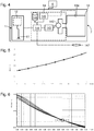
- the figure 5 illustrates such a diagram with steps in H0 field levels in increments of 0.2 mA / mc from 1.1 mA / m c.
- the method of determining the distance zp can be as follows.
- abnormal measurements are initially initially rejected. For this, we eliminate the measures moving too far from the model provided for example by the diagram of the figure 5 . If too many measurements deviate from the model, the processing circuit 144 may decide that the estimation of the distance between the label 2 and the ground 5 is uncertain and require a renewal of the measurement by the manipulator.
- an estimate of the electromagnetic field generated in the ground by the device 7 is calculated when its antenna is positioned at the distance zek stored in the memory 146. This is based on a distribution model the field generated by the antenna of the device 7. It is also possible to store reference electromagnetic field profiles and extrapolate the distribution of the electromagnetic field sought for the various measurements by interpolation between the stored profiles. As illustrated in figure 6 , it is possible to determine the distributions of the field of the antenna of the device 7 at the vertical of the label 2 for the different measurements. For each measurement, a field diagram at label 2 is plotted versus distance from the surface. The distance zp is determined by determining the distance indicated by the intersection of several of these diagrams.
- N the number of diagrams or stored measurements.
- a single intersection can be determined by interpolation between the multiple calculated intersections, eliminating intersections where necessary with too much dispersion over the others.
- Such a mode of determining the distance zp is advantageously independent of the performance of the tag 2 (quality factor and tuning frequency of its antenna) and of their evolution over time as a function of aging or changes in ground conditions. or climate.
Landscapes
- Physics & Mathematics (AREA)
- Engineering & Computer Science (AREA)
- General Physics & Mathematics (AREA)
- Toxicology (AREA)
- Health & Medical Sciences (AREA)
- Geophysics (AREA)
- General Life Sciences & Earth Sciences (AREA)
- Life Sciences & Earth Sciences (AREA)
- Electromagnetism (AREA)
- General Health & Medical Sciences (AREA)
- Artificial Intelligence (AREA)
- Computer Vision & Pattern Recognition (AREA)
- Theoretical Computer Science (AREA)
- Computer Networks & Wireless Communication (AREA)
- Radar Systems Or Details Thereof (AREA)
- Geophysics And Detection Of Objects (AREA)
- Near-Field Transmission Systems (AREA)
Applications Claiming Priority (2)
| Application Number | Priority Date | Filing Date | Title |
|---|---|---|---|
| FR1252081A FR2987904B1 (fr) | 2012-03-07 | 2012-03-07 | Dispositif d'evaluation de la distance entre une etiquette rfid et une interface |
| PCT/EP2013/054534 WO2013131975A2 (fr) | 2012-03-07 | 2013-03-06 | Dispositif de localisation pour l'evaluation de la distance entre une etiquette rfid et une interface |
Publications (2)
| Publication Number | Publication Date |
|---|---|
| EP2823339A2 EP2823339A2 (fr) | 2015-01-14 |
| EP2823339B1 true EP2823339B1 (fr) | 2019-01-16 |
Family
ID=47827224
Family Applications (1)
| Application Number | Title | Priority Date | Filing Date |
|---|---|---|---|
| EP13707651.9A Active EP2823339B1 (fr) | 2012-03-07 | 2013-03-06 | Dispositif de localisation pour l'evaluation de la distance entre une etiquette rfid et une interface |
Country Status (14)
| Country | Link |
|---|---|
| US (1) | US9424448B2 (enExample) |
| EP (1) | EP2823339B1 (enExample) |
| JP (1) | JP6204929B2 (enExample) |
| CN (1) | CN104160301B (enExample) |
| AU (1) | AU2013229546B2 (enExample) |
| CA (1) | CA2866391C (enExample) |
| FR (1) | FR2987904B1 (enExample) |
| IN (1) | IN2014MN01664A (enExample) |
| MA (1) | MA35925B1 (enExample) |
| MX (1) | MX341253B (enExample) |
| NZ (1) | NZ629347A (enExample) |
| RU (1) | RU2619818C2 (enExample) |
| TN (1) | TN2014000349A1 (enExample) |
| WO (1) | WO2013131975A2 (enExample) |
Families Citing this family (7)
| Publication number | Priority date | Publication date | Assignee | Title |
|---|---|---|---|---|
| US10866227B2 (en) * | 2014-02-03 | 2020-12-15 | Goldin-Rudahl Systems, Inc. | Early warning system for road, runway, and railway failures |
| CN106842110A (zh) * | 2017-03-06 | 2017-06-13 | 常州港华燃气有限公司 | 地下管道信标定位装置 |
| CN107478914A (zh) * | 2017-08-04 | 2017-12-15 | 歌尔股份有限公司 | 天线检测装置、系统及方法 |
| CN108594027B (zh) * | 2018-03-28 | 2023-05-26 | 武汉纺织大学 | 一种多辐射单元天线测试箱及测试方法 |
| US11415669B2 (en) * | 2019-01-11 | 2022-08-16 | Nec Corporation | Walk-through gate with signal separation |
| CN110588728A (zh) * | 2019-10-22 | 2019-12-20 | 哈尔滨铁路减速顶调速研究有限公司 | 一种铁路用无联锁接发列车进路确认系统 |
| CA3163305A1 (en) * | 2019-12-28 | 2021-07-01 | Mark Roth | Shopping cart/basket reader systems and methods |
Family Cites Families (17)
| Publication number | Priority date | Publication date | Assignee | Title |
|---|---|---|---|---|
| US6097189A (en) * | 1997-09-29 | 2000-08-01 | The United States Of America As Represented By The Administrator Of The National Aeronautics And Space Administration | Object locating system |
| US5945920A (en) * | 1997-12-10 | 1999-08-31 | Atmel Corporation | Minimum voltage radio frequency indentification |
| JPH11352240A (ja) * | 1998-06-04 | 1999-12-24 | Waimu Up Kk | 埋設管用位置検知システム |
| JP3614157B2 (ja) * | 2002-07-30 | 2005-01-26 | オムロン株式会社 | Rfidタグならびにrfidタグにおける共振周波数の調整方法 |
| JP2004347443A (ja) * | 2003-05-22 | 2004-12-09 | Matsushita Electric Ind Co Ltd | 検査装置 |
| JP2005181111A (ja) * | 2003-12-19 | 2005-07-07 | Dekku:Kk | 埋設管情報の読取装置 |
| JP2006071516A (ja) * | 2004-09-03 | 2006-03-16 | Fujitsu Support & Service Kk | Icタグ位置特定装置およびicタグ位置特定方法 |
| JP2007192736A (ja) * | 2006-01-20 | 2007-08-02 | Nippon Telegraph & Telephone West Corp | 移動体監視システム |
| US20070290846A1 (en) * | 2006-06-07 | 2007-12-20 | Meinhard Schilling | Concept for determining the position or orientation of a transponder in an RFID system |
| CN101135728A (zh) * | 2006-08-28 | 2008-03-05 | 西门子(中国)有限公司 | Rfid定位发射接收装置、系统和方法 |
| JP4452782B2 (ja) * | 2006-12-20 | 2010-04-21 | 仁川大學校産學協力團 | Rfidリーダ用多重ループアンテナ、これを有するrfidリーダ、及びこれを有するrfidシステム |
| JP2009075032A (ja) * | 2007-09-25 | 2009-04-09 | Kobe Steel Ltd | 位置検出システム |
| JP2009222590A (ja) * | 2008-03-17 | 2009-10-01 | Fujitsu Ltd | 試験装置および試験方法 |
| JP2010266227A (ja) * | 2009-05-12 | 2010-11-25 | Pinetech Co Ltd | Rfidタグ位置検出システム |
| CA2777553A1 (en) * | 2010-01-27 | 2011-08-04 | Berntsen International, Inc. | Locator assembly for detecting, locating and identifying buried objects and method of use |
| JP5520090B2 (ja) * | 2010-03-10 | 2014-06-11 | 株式会社富士通アドバンストエンジニアリング | 探索支援装置、探索支援方法、及びプログラム |
| FR2961354B1 (fr) | 2010-06-15 | 2012-06-01 | Commissariat Energie Atomique | Antenne haute frequence |
-
2012
- 2012-03-07 FR FR1252081A patent/FR2987904B1/fr not_active Expired - Fee Related
-
2013
- 2013-03-06 NZ NZ629347A patent/NZ629347A/en not_active IP Right Cessation
- 2013-03-06 CN CN201380012852.6A patent/CN104160301B/zh not_active Expired - Fee Related
- 2013-03-06 WO PCT/EP2013/054534 patent/WO2013131975A2/fr not_active Ceased
- 2013-03-06 IN IN1664MUN2014 patent/IN2014MN01664A/en unknown
- 2013-03-06 AU AU2013229546A patent/AU2013229546B2/en not_active Ceased
- 2013-03-06 JP JP2014560361A patent/JP6204929B2/ja not_active Expired - Fee Related
- 2013-03-06 RU RU2014140311A patent/RU2619818C2/ru active
- 2013-03-06 US US14/383,692 patent/US9424448B2/en active Active
- 2013-03-06 CA CA2866391A patent/CA2866391C/fr not_active Expired - Fee Related
- 2013-03-06 EP EP13707651.9A patent/EP2823339B1/fr active Active
- 2013-03-06 MX MX2014010657A patent/MX341253B/es active IP Right Grant
-
2014
- 2014-08-08 TN TNP2014000349A patent/TN2014000349A1/fr unknown
- 2014-09-05 MA MA37328A patent/MA35925B1/fr unknown
Non-Patent Citations (1)
| Title |
|---|
| None * |
Also Published As
| Publication number | Publication date |
|---|---|
| CN104160301A (zh) | 2014-11-19 |
| FR2987904A1 (fr) | 2013-09-13 |
| CA2866391A1 (fr) | 2013-09-12 |
| MX341253B (es) | 2016-08-09 |
| JP6204929B2 (ja) | 2017-09-27 |
| MA35925B1 (fr) | 2014-12-01 |
| JP2015516564A (ja) | 2015-06-11 |
| IN2014MN01664A (enExample) | 2015-05-29 |
| CN104160301B (zh) | 2017-10-20 |
| US9424448B2 (en) | 2016-08-23 |
| TN2014000349A1 (fr) | 2015-12-21 |
| NZ629347A (en) | 2015-11-27 |
| RU2014140311A (ru) | 2016-04-27 |
| RU2619818C2 (ru) | 2017-05-18 |
| WO2013131975A3 (fr) | 2013-10-31 |
| WO2013131975A2 (fr) | 2013-09-12 |
| EP2823339A2 (fr) | 2015-01-14 |
| AU2013229546B2 (en) | 2015-11-26 |
| CA2866391C (fr) | 2018-11-20 |
| AU2013229546A1 (en) | 2014-09-25 |
| US20150054623A1 (en) | 2015-02-26 |
| MX2014010657A (es) | 2015-06-23 |
| FR2987904B1 (fr) | 2014-03-21 |
Similar Documents
| Publication | Publication Date | Title |
|---|---|---|
| EP2823339B1 (fr) | Dispositif de localisation pour l'evaluation de la distance entre une etiquette rfid et une interface | |
| US12278503B2 (en) | Wireless power systems with foreign object detection | |
| EP2299288B1 (fr) | Procédé et système de localisation d'une personne, support d'enregistrement pour ce procédé | |
| RU2459217C2 (ru) | Радиочастотная навигация с использованием сопоставления частотных характеристик | |
| WO2011157753A1 (fr) | Procede de localisation de zone d'emission de decharge partielle et dispositif associe | |
| WO2010052234A1 (fr) | Procede de determination de la direction d'arrivee en gisement d'une onde electromagnetique hautes frequences | |
| US9404831B2 (en) | Arrayed wave division multiplex to extend range of IOFDR fiber bragg sensing system | |
| KR101281597B1 (ko) | 균열 검사 시스템 | |
| WO2017089592A1 (fr) | Procede de detection de presence de transpondeur radiofrequence par simulation de couplage electromagnetique | |
| FR3098305A1 (fr) | Procédé de détermination d’au moins un emplacement pour la réception d’un signal ambiant rétrodiffusé | |
| EP3632012A1 (fr) | Dispositif de mise en forme d'onde et récepteur d'onde | |
| US20210406862A1 (en) | Method and System for Detecting Filling Parameters of a Point-of-Sale Display | |
| EP2299289A1 (fr) | Procédé et système de détermination de l'activité d'une personne, support d'enregistrement pour ce procédé | |
| EP2691911A1 (fr) | Procédé et dispositif de repérage de la position d'un transpondeur | |
| FR3098304A1 (fr) | Procédé de détermination d’au moins un emplacement pour la réception améliorée d’un signal ambiant rétrodiffusé | |
| FR3092173A1 (fr) | Procédé de suivi de temps d’utilisation d’un groupe électrogène, dispositif autonome, procédé de suivi de la maintenance, et système correspondants. | |
| WO2019092107A1 (fr) | Systeme de securite electronique pour robots mobiles | |
| FR2667952A1 (fr) | Dispositif pour la detection, l'identification et le suivi de canalisations enterrees ou autres objets optiquement invisibles. | |
| EP1850627B1 (fr) | Détermination d'une zone de localisation d'un terminal par rapport à une région géographique determinée | |
| FR3146245A1 (fr) | Procede de detection d’un objet a charger sur un dispositif de charge et dispositif de charge associe | |
| FR3149997A1 (fr) | Procédé et dispositif de localisation d’une fibre optique | |
| KR101658468B1 (ko) | 무선 센서 네트워크 장치 및 그 제어방법 | |
| CN105092533B (zh) | 一种片体的区域的监测方法及设备 | |
| FR3141031A1 (fr) | Procede et systeme d’inventaire dans un espace limite par une enceinte | |
| FR3125330A1 (fr) | Dispositif d'émission et/ou détection d'ondes acoustiques à fréquence de résonnance variable |
Legal Events
| Date | Code | Title | Description |
|---|---|---|---|
| PUAI | Public reference made under article 153(3) epc to a published international application that has entered the european phase |
Free format text: ORIGINAL CODE: 0009012 |
|
| 17P | Request for examination filed |
Effective date: 20140904 |
|
| AK | Designated contracting states |
Kind code of ref document: A2 Designated state(s): AL AT BE BG CH CY CZ DE DK EE ES FI FR GB GR HR HU IE IS IT LI LT LU LV MC MK MT NL NO PL PT RO RS SE SI SK SM TR |
|
| AX | Request for extension of the european patent |
Extension state: BA ME |
|
| DAX | Request for extension of the european patent (deleted) | ||
| STAA | Information on the status of an ep patent application or granted ep patent |
Free format text: STATUS: EXAMINATION IS IN PROGRESS |
|
| 17Q | First examination report despatched |
Effective date: 20180215 |
|
| GRAP | Despatch of communication of intention to grant a patent |
Free format text: ORIGINAL CODE: EPIDOSNIGR1 |
|
| STAA | Information on the status of an ep patent application or granted ep patent |
Free format text: STATUS: GRANT OF PATENT IS INTENDED |
|
| INTG | Intention to grant announced |
Effective date: 20180810 |
|
| GRAS | Grant fee paid |
Free format text: ORIGINAL CODE: EPIDOSNIGR3 |
|
| GRAA | (expected) grant |
Free format text: ORIGINAL CODE: 0009210 |
|
| STAA | Information on the status of an ep patent application or granted ep patent |
Free format text: STATUS: THE PATENT HAS BEEN GRANTED |
|
| AK | Designated contracting states |
Kind code of ref document: B1 Designated state(s): AL AT BE BG CH CY CZ DE DK EE ES FI FR GB GR HR HU IE IS IT LI LT LU LV MC MK MT NL NO PL PT RO RS SE SI SK SM TR |
|
| REG | Reference to a national code |
Ref country code: GB Ref legal event code: FG4D Free format text: NOT ENGLISH |
|
| REG | Reference to a national code |
Ref country code: CH Ref legal event code: EP |
|
| REG | Reference to a national code |
Ref country code: IE Ref legal event code: FG4D Free format text: LANGUAGE OF EP DOCUMENT: FRENCH |
|
| REG | Reference to a national code |
Ref country code: DE Ref legal event code: R096 Ref document number: 602013049850 Country of ref document: DE |
|
| REG | Reference to a national code |
Ref country code: AT Ref legal event code: REF Ref document number: 1090127 Country of ref document: AT Kind code of ref document: T Effective date: 20190215 |
|
| REG | Reference to a national code |
Ref country code: NL Ref legal event code: MP Effective date: 20190116 |
|
| REG | Reference to a national code |
Ref country code: LT Ref legal event code: MG4D |
|
| PG25 | Lapsed in a contracting state [announced via postgrant information from national office to epo] |
Ref country code: NL Free format text: LAPSE BECAUSE OF FAILURE TO SUBMIT A TRANSLATION OF THE DESCRIPTION OR TO PAY THE FEE WITHIN THE PRESCRIBED TIME-LIMIT Effective date: 20190116 |
|
| REG | Reference to a national code |
Ref country code: AT Ref legal event code: MK05 Ref document number: 1090127 Country of ref document: AT Kind code of ref document: T Effective date: 20190116 |
|
| PG25 | Lapsed in a contracting state [announced via postgrant information from national office to epo] |
Ref country code: ES Free format text: LAPSE BECAUSE OF FAILURE TO SUBMIT A TRANSLATION OF THE DESCRIPTION OR TO PAY THE FEE WITHIN THE PRESCRIBED TIME-LIMIT Effective date: 20190116 Ref country code: PL Free format text: LAPSE BECAUSE OF FAILURE TO SUBMIT A TRANSLATION OF THE DESCRIPTION OR TO PAY THE FEE WITHIN THE PRESCRIBED TIME-LIMIT Effective date: 20190116 Ref country code: FI Free format text: LAPSE BECAUSE OF FAILURE TO SUBMIT A TRANSLATION OF THE DESCRIPTION OR TO PAY THE FEE WITHIN THE PRESCRIBED TIME-LIMIT Effective date: 20190116 Ref country code: LT Free format text: LAPSE BECAUSE OF FAILURE TO SUBMIT A TRANSLATION OF THE DESCRIPTION OR TO PAY THE FEE WITHIN THE PRESCRIBED TIME-LIMIT Effective date: 20190116 Ref country code: SE Free format text: LAPSE BECAUSE OF FAILURE TO SUBMIT A TRANSLATION OF THE DESCRIPTION OR TO PAY THE FEE WITHIN THE PRESCRIBED TIME-LIMIT Effective date: 20190116 Ref country code: PT Free format text: LAPSE BECAUSE OF FAILURE TO SUBMIT A TRANSLATION OF THE DESCRIPTION OR TO PAY THE FEE WITHIN THE PRESCRIBED TIME-LIMIT Effective date: 20190516 Ref country code: NO Free format text: LAPSE BECAUSE OF FAILURE TO SUBMIT A TRANSLATION OF THE DESCRIPTION OR TO PAY THE FEE WITHIN THE PRESCRIBED TIME-LIMIT Effective date: 20190416 |
|
| PG25 | Lapsed in a contracting state [announced via postgrant information from national office to epo] |
Ref country code: BG Free format text: LAPSE BECAUSE OF FAILURE TO SUBMIT A TRANSLATION OF THE DESCRIPTION OR TO PAY THE FEE WITHIN THE PRESCRIBED TIME-LIMIT Effective date: 20190416 Ref country code: RS Free format text: LAPSE BECAUSE OF FAILURE TO SUBMIT A TRANSLATION OF THE DESCRIPTION OR TO PAY THE FEE WITHIN THE PRESCRIBED TIME-LIMIT Effective date: 20190116 Ref country code: LV Free format text: LAPSE BECAUSE OF FAILURE TO SUBMIT A TRANSLATION OF THE DESCRIPTION OR TO PAY THE FEE WITHIN THE PRESCRIBED TIME-LIMIT Effective date: 20190116 Ref country code: IS Free format text: LAPSE BECAUSE OF FAILURE TO SUBMIT A TRANSLATION OF THE DESCRIPTION OR TO PAY THE FEE WITHIN THE PRESCRIBED TIME-LIMIT Effective date: 20190516 Ref country code: HR Free format text: LAPSE BECAUSE OF FAILURE TO SUBMIT A TRANSLATION OF THE DESCRIPTION OR TO PAY THE FEE WITHIN THE PRESCRIBED TIME-LIMIT Effective date: 20190116 Ref country code: GR Free format text: LAPSE BECAUSE OF FAILURE TO SUBMIT A TRANSLATION OF THE DESCRIPTION OR TO PAY THE FEE WITHIN THE PRESCRIBED TIME-LIMIT Effective date: 20190417 |
|
| REG | Reference to a national code |
Ref country code: DE Ref legal event code: R097 Ref document number: 602013049850 Country of ref document: DE |
|
| PG25 | Lapsed in a contracting state [announced via postgrant information from national office to epo] |
Ref country code: SK Free format text: LAPSE BECAUSE OF FAILURE TO SUBMIT A TRANSLATION OF THE DESCRIPTION OR TO PAY THE FEE WITHIN THE PRESCRIBED TIME-LIMIT Effective date: 20190116 Ref country code: IT Free format text: LAPSE BECAUSE OF FAILURE TO SUBMIT A TRANSLATION OF THE DESCRIPTION OR TO PAY THE FEE WITHIN THE PRESCRIBED TIME-LIMIT Effective date: 20190116 Ref country code: RO Free format text: LAPSE BECAUSE OF FAILURE TO SUBMIT A TRANSLATION OF THE DESCRIPTION OR TO PAY THE FEE WITHIN THE PRESCRIBED TIME-LIMIT Effective date: 20190116 Ref country code: EE Free format text: LAPSE BECAUSE OF FAILURE TO SUBMIT A TRANSLATION OF THE DESCRIPTION OR TO PAY THE FEE WITHIN THE PRESCRIBED TIME-LIMIT Effective date: 20190116 Ref country code: CZ Free format text: LAPSE BECAUSE OF FAILURE TO SUBMIT A TRANSLATION OF THE DESCRIPTION OR TO PAY THE FEE WITHIN THE PRESCRIBED TIME-LIMIT Effective date: 20190116 Ref country code: MC Free format text: LAPSE BECAUSE OF FAILURE TO SUBMIT A TRANSLATION OF THE DESCRIPTION OR TO PAY THE FEE WITHIN THE PRESCRIBED TIME-LIMIT Effective date: 20190116 Ref country code: AL Free format text: LAPSE BECAUSE OF FAILURE TO SUBMIT A TRANSLATION OF THE DESCRIPTION OR TO PAY THE FEE WITHIN THE PRESCRIBED TIME-LIMIT Effective date: 20190116 Ref country code: AT Free format text: LAPSE BECAUSE OF FAILURE TO SUBMIT A TRANSLATION OF THE DESCRIPTION OR TO PAY THE FEE WITHIN THE PRESCRIBED TIME-LIMIT Effective date: 20190116 Ref country code: DK Free format text: LAPSE BECAUSE OF FAILURE TO SUBMIT A TRANSLATION OF THE DESCRIPTION OR TO PAY THE FEE WITHIN THE PRESCRIBED TIME-LIMIT Effective date: 20190116 |
|
| REG | Reference to a national code |
Ref country code: CH Ref legal event code: PL |
|
| PLBE | No opposition filed within time limit |
Free format text: ORIGINAL CODE: 0009261 |
|
| STAA | Information on the status of an ep patent application or granted ep patent |
Free format text: STATUS: NO OPPOSITION FILED WITHIN TIME LIMIT |
|
| PG25 | Lapsed in a contracting state [announced via postgrant information from national office to epo] |
Ref country code: SM Free format text: LAPSE BECAUSE OF FAILURE TO SUBMIT A TRANSLATION OF THE DESCRIPTION OR TO PAY THE FEE WITHIN THE PRESCRIBED TIME-LIMIT Effective date: 20190116 Ref country code: LU Free format text: LAPSE BECAUSE OF NON-PAYMENT OF DUE FEES Effective date: 20190306 |
|
| REG | Reference to a national code |
Ref country code: BE Ref legal event code: MM Effective date: 20190331 |
|
| 26N | No opposition filed |
Effective date: 20191017 |
|
| PG25 | Lapsed in a contracting state [announced via postgrant information from national office to epo] |
Ref country code: CH Free format text: LAPSE BECAUSE OF NON-PAYMENT OF DUE FEES Effective date: 20190331 Ref country code: IE Free format text: LAPSE BECAUSE OF NON-PAYMENT OF DUE FEES Effective date: 20190306 Ref country code: LI Free format text: LAPSE BECAUSE OF NON-PAYMENT OF DUE FEES Effective date: 20190331 |
|
| PG25 | Lapsed in a contracting state [announced via postgrant information from national office to epo] |
Ref country code: BE Free format text: LAPSE BECAUSE OF NON-PAYMENT OF DUE FEES Effective date: 20190331 Ref country code: SI Free format text: LAPSE BECAUSE OF FAILURE TO SUBMIT A TRANSLATION OF THE DESCRIPTION OR TO PAY THE FEE WITHIN THE PRESCRIBED TIME-LIMIT Effective date: 20190116 |
|
| PG25 | Lapsed in a contracting state [announced via postgrant information from national office to epo] |
Ref country code: TR Free format text: LAPSE BECAUSE OF FAILURE TO SUBMIT A TRANSLATION OF THE DESCRIPTION OR TO PAY THE FEE WITHIN THE PRESCRIBED TIME-LIMIT Effective date: 20190116 |
|
| PG25 | Lapsed in a contracting state [announced via postgrant information from national office to epo] |
Ref country code: MT Free format text: LAPSE BECAUSE OF FAILURE TO SUBMIT A TRANSLATION OF THE DESCRIPTION OR TO PAY THE FEE WITHIN THE PRESCRIBED TIME-LIMIT Effective date: 20190116 |
|
| PG25 | Lapsed in a contracting state [announced via postgrant information from national office to epo] |
Ref country code: CY Free format text: LAPSE BECAUSE OF FAILURE TO SUBMIT A TRANSLATION OF THE DESCRIPTION OR TO PAY THE FEE WITHIN THE PRESCRIBED TIME-LIMIT Effective date: 20190116 |
|
| PG25 | Lapsed in a contracting state [announced via postgrant information from national office to epo] |
Ref country code: HU Free format text: LAPSE BECAUSE OF FAILURE TO SUBMIT A TRANSLATION OF THE DESCRIPTION OR TO PAY THE FEE WITHIN THE PRESCRIBED TIME-LIMIT; INVALID AB INITIO Effective date: 20130306 |
|
| PG25 | Lapsed in a contracting state [announced via postgrant information from national office to epo] |
Ref country code: MK Free format text: LAPSE BECAUSE OF FAILURE TO SUBMIT A TRANSLATION OF THE DESCRIPTION OR TO PAY THE FEE WITHIN THE PRESCRIBED TIME-LIMIT Effective date: 20190116 |
|
| PGFP | Annual fee paid to national office [announced via postgrant information from national office to epo] |
Ref country code: DE Payment date: 20240321 Year of fee payment: 12 Ref country code: GB Payment date: 20240318 Year of fee payment: 12 |
|
| PGFP | Annual fee paid to national office [announced via postgrant information from national office to epo] |
Ref country code: FR Payment date: 20240320 Year of fee payment: 12 |
|
| REG | Reference to a national code |
Ref country code: DE Ref legal event code: R119 Ref document number: 602013049850 Country of ref document: DE |
|
| GBPC | Gb: european patent ceased through non-payment of renewal fee |
Effective date: 20250306 |