EP2822174A2 - Apparatus for determining start of electric machine - Google Patents
Apparatus for determining start of electric machine Download PDFInfo
- Publication number
- EP2822174A2 EP2822174A2 EP14173425.1A EP14173425A EP2822174A2 EP 2822174 A2 EP2822174 A2 EP 2822174A2 EP 14173425 A EP14173425 A EP 14173425A EP 2822174 A2 EP2822174 A2 EP 2822174A2
- Authority
- EP
- European Patent Office
- Prior art keywords
- frequency
- motor
- estimator
- current
- phase
- Prior art date
- Legal status (The legal status is an assumption and is not a legal conclusion. Google has not performed a legal analysis and makes no representation as to the accuracy of the status listed.)
- Granted
Links
- 230000001360 synchronised effect Effects 0.000 description 12
- 238000010586 diagram Methods 0.000 description 8
- 238000012986 modification Methods 0.000 description 3
- 230000004048 modification Effects 0.000 description 3
- 230000000694 effects Effects 0.000 description 2
- 230000006698 induction Effects 0.000 description 2
- 230000004075 alteration Effects 0.000 description 1
- 230000004907 flux Effects 0.000 description 1
- 238000012423 maintenance Methods 0.000 description 1
- 238000000034 method Methods 0.000 description 1
Images


Classifications
-
- H—ELECTRICITY
- H02—GENERATION; CONVERSION OR DISTRIBUTION OF ELECTRIC POWER
- H02P—CONTROL OR REGULATION OF ELECTRIC MOTORS, ELECTRIC GENERATORS OR DYNAMO-ELECTRIC CONVERTERS; CONTROLLING TRANSFORMERS, REACTORS OR CHOKE COILS
- H02P1/00—Arrangements for starting electric motors or dynamo-electric converters
- H02P1/16—Arrangements for starting electric motors or dynamo-electric converters for starting dynamo-electric motors or dynamo-electric converters
- H02P1/26—Arrangements for starting electric motors or dynamo-electric converters for starting dynamo-electric motors or dynamo-electric converters for starting an individual polyphase induction motor
-
- H—ELECTRICITY
- H02—GENERATION; CONVERSION OR DISTRIBUTION OF ELECTRIC POWER
- H02P—CONTROL OR REGULATION OF ELECTRIC MOTORS, ELECTRIC GENERATORS OR DYNAMO-ELECTRIC CONVERTERS; CONTROLLING TRANSFORMERS, REACTORS OR CHOKE COILS
- H02P1/00—Arrangements for starting electric motors or dynamo-electric converters
- H02P1/16—Arrangements for starting electric motors or dynamo-electric converters for starting dynamo-electric motors or dynamo-electric converters
- H02P1/26—Arrangements for starting electric motors or dynamo-electric converters for starting dynamo-electric motors or dynamo-electric converters for starting an individual polyphase induction motor
- H02P1/265—Means for starting or running a triphase motor on a single phase supply
-
- H—ELECTRICITY
- H02—GENERATION; CONVERSION OR DISTRIBUTION OF ELECTRIC POWER
- H02P—CONTROL OR REGULATION OF ELECTRIC MOTORS, ELECTRIC GENERATORS OR DYNAMO-ELECTRIC CONVERTERS; CONTROLLING TRANSFORMERS, REACTORS OR CHOKE COILS
- H02P21/00—Arrangements or methods for the control of electric machines by vector control, e.g. by control of field orientation
- H02P21/14—Estimation or adaptation of machine parameters, e.g. flux, current or voltage
- H02P21/18—Estimation of position or speed
-
- H—ELECTRICITY
- H02—GENERATION; CONVERSION OR DISTRIBUTION OF ELECTRIC POWER
- H02P—CONTROL OR REGULATION OF ELECTRIC MOTORS, ELECTRIC GENERATORS OR DYNAMO-ELECTRIC CONVERTERS; CONTROLLING TRANSFORMERS, REACTORS OR CHOKE COILS
- H02P6/00—Arrangements for controlling synchronous motors or other dynamo-electric motors using electronic commutation dependent on the rotor position; Electronic commutators therefor
- H02P6/14—Electronic commutators
- H02P6/16—Circuit arrangements for detecting position
- H02P6/18—Circuit arrangements for detecting position without separate position detecting elements
-
- H—ELECTRICITY
- H02—GENERATION; CONVERSION OR DISTRIBUTION OF ELECTRIC POWER
- H02P—CONTROL OR REGULATION OF ELECTRIC MOTORS, ELECTRIC GENERATORS OR DYNAMO-ELECTRIC CONVERTERS; CONTROLLING TRANSFORMERS, REACTORS OR CHOKE COILS
- H02P6/00—Arrangements for controlling synchronous motors or other dynamo-electric motors using electronic commutation dependent on the rotor position; Electronic commutators therefor
- H02P6/20—Arrangements for starting
-
- H—ELECTRICITY
- H02—GENERATION; CONVERSION OR DISTRIBUTION OF ELECTRIC POWER
- H02P—CONTROL OR REGULATION OF ELECTRIC MOTORS, ELECTRIC GENERATORS OR DYNAMO-ELECTRIC CONVERTERS; CONTROLLING TRANSFORMERS, REACTORS OR CHOKE COILS
- H02P2207/00—Indexing scheme relating to controlling arrangements characterised by the type of motor
- H02P2207/05—Synchronous machines, e.g. with permanent magnets or DC excitation
Definitions
- the teachings in accordance with the exemplary embodiments of this present disclosure generally relate to an apparatus for determining start of electric machine.
- 3-phase motors such as induction motors and synchronous machines are differentiated in operation methods when with a position sensor and when without a position sensor.
- the position sensor such as an encoder and a resolver is frequently used to measure a position and a speed of a rotor, but use of the position sensor disadvantageously increases costs of an entire system, maintenance costs and the volume of the entire system in addition to being weak to fault.
- the industries require a demand on sensor-less operation of a 3-phase motor free from a position sensor.
- conventional sensor-less operation of 3-phase motor suffers from failure to determine start of the motor after start of sensor-less operation, which is generated by an error between rotor speed and position estimation.
- the present disclosure is to provide an apparatus for determining start of electric machine configured to determine whether start has successfully made during sensor-less operation of a 3-phase electric machine.
- the present disclosure is also to provide an apparatus for determining start of electric machine configured to allow a motor to continuously operate when start has successfully made during sensor-less operation and to stop operating and to re-start when the motor has failed to start.
- an apparatus for determining start of electric machine comprising:
- the apparatus may further comprise a bandwidth decision unit configured to decide a control bandwidth of the estimator.
- a control bandwidth decided by the bandwidth decision unit may be decided by a gain of the estimator.
- the gain of the estimator may be selected of a value higher than an operation frequency of the 3-phase motor.
- the estimator may receive a positive input frequency inoperable by the motor to output the input frequency when start of the motor is not made and to determine whether the start of the motor has successfully made.
- the determinator may determine that the start has failed when a difference between the frequency estimated by the estimator and the frequency of output voltage of the inverter.
- the present disclosure thus discussed has an advantageous effect in that a frequency of a phase current inputted into a 3-phase motor during sensor-less operation of the motor is estimated to determine whether the motor has successfully started by comparing the frequency of the phase current with a frequency of an output voltage of an inverter configured to control the motor.
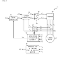
- FIG.1 is a block diagram illustrating a motor control system according to the present disclosure, where the motor control system (1) according to an exemplary embodiment of the present disclosure operates a 3-phase motor (2), and where the motor (2) may be an induction motor or a synchronous motor, for example.
- the motor control system (1) may include a speed controller (10), a current controller (20), a first converter (30), a second converter (40), an inverter (50), a rotor speed and position estimator (60), a current measurer (70: 70a, 70b, 70c) and an apparatus (80) for determining start of electric machine, where the apparatus (80) for determining start of electric machine (hereinafter referred to as apparatus) in the control system (1) of the present disclosure determines whether the start of the motor (2) is successful and transmits the determination to a higher level controller (not shown).
- the speed controller (10) uses a rotor speed command and an actual rotor speed as input and outputs a q-axis current command on a synchronous reference frame.
- the current controller (20) outputs d, q voltages of the synchronous reference frame from d, q axis current command of the synchronous reference frame and an actual current.
- the first converter (30) converts an output voltage of the current controller (20) to a voltage on a stationary reference frame.
- the second converter (40) converts a phase current of the motor (2) measured by the current measurer (70) to d, q axis current on the synchronous reference frame.
- the inverter (50) applies a voltage to the motor (2) and the rotor speed and position estimator (60) uses the phase current measured by the current measurer (70) and the output voltage of the first converter (30) as input to estimate a rotor speed and a rotor position.
- the current measurer (70) measures a phase current inputted from the motor (2).
- the apparatus (80) may output 'S' when start of the motor (2) is successful, and output 'F' when the start of the motor (2) is unsuccessful, and may transmit the output to a higher controller (not shown).
- the apparatus (80) may additionally output a signal for restart. Now, each component will be described in detail.
- FIG.2 is a detailed block diagram illustrating a speed controller (10) of FIG. 1 .
- the speed controller (10) outputs a q-axis current command according to a difference between a speed reference and a feedback speed using proportional and integral control.
- the speed controller (10) according to the present disclosure may include proportional and integral controllers (11a, 11b), a limiter (12) and an anti-windup gain setting unit (13), where the limiter (12) limits an output of the speed controller (10) and the gain setting unit (13) serves to prevent divergence of the integral controller (11b) when the limiter (12) operates.
- An output of the speed controller (10) becomes a q-axis current on the synchronous reference frame.
- FIGS.3a and 3b are detailed block diagrams illustrating a current controller (20) of FIG. 1 , where FIG.3a is a configuration of a d-axis current controller of the synchronous reference frame, and FIG.3b is a configuration of q-axis current controller on the synchronous reference frame.
- the d, q axis current controller may include a proportional and integral controller for respectively controlling d, q axis currents on the synchronous reference frame and a feed-forward. That is, the current controller (20) of the present disclosure includes proportional and integral controllers (21a, 21b, 24a, 24b) configured to control a current from a current command and a feedback current, feed-forwards (22, 25) and anti-windup gain setting units (23, 26).
- the feed-forwards (22, 25) may variably be configured according to modeling of the 3-phase motor (2). Furthermore, the gain setting units (23, 26) serve to prevent divergence of the integral controllers (21b, 24b) when an output of the current controller (20) deviates the size of voltage synthesizable by the inverter (50).
- the first converter (30) of FIG. 1 converts the voltage on the synchronous reference frame which is an output of the current controller (20) to a voltage on the stationary reference frame, and outputs an output as expressed by the following Equations.
- V ds s V ds e * ⁇ cos ⁇ e - V qs e * ⁇ sin ⁇ e
- V qs s V ds e * ⁇ sin ⁇ e + V qs e * ⁇ cos ⁇ e
- the second converter (20) outputs d, q axis current on the synchronous reference frame from the phase current of the motor (2) received from the current measurer (70) according to the following Equations.
- i ds s 2 ⁇ i as - i bs - i cs 3
- i qs s i bs - i cs 3
- the rotor speed and positions estimator (60) uses the current inputted from the motor (2) and the voltage inputted from the inverter (50) as inputs to output a rotor speed and a rotor flux position, the detailed configuration of which is well known to the skilled in the art such that no further elaboration thereto will be made.
- the apparatus (80) in FIG. 1 determines the start of the motor (2) using a frequency of current inputted from the motor (2). Although FIG. 1 illustrates that the apparatus (80) receives all input currents of the motor (2) from the current measurer (70), the apparatus (80) may receive one or two currents.
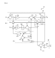
- FIG. 4 is a detailed block diagram illustrating an apparatus for determining start of electric machine.
- the apparatus (80) of the present disclosure may include a current converter (81), a frequency estimator (82), a bandwidth decision unit (83) and a determinator (84).
- the frequency estimator (82) estimates a frequency of phase current inputted from the motor (2), and includes deductors (82a, 82b), a gain setting unit (82c), an integrator (82d) and adder (82e).
- the bandwidth decision unit (83) decides a control bandwidth of the frequency estimator (82), and includes multipliers (83a, 83b), an adder (83c), a divider (83d) and a gain setting unit (83e).
- the determinator (84) uses the output of the frequency estimator (82) of the motor (2) to determine whether start has been successful, and includes a deductor (84a) and a decision unit (84b).
- the current converter (81) may decide i' xs and qi' xs using the following Equations.
- Equation 8 Only frequency component of ⁇ ' may be extracted from the measured phase current of motor (2) from Equation 7, and a signal lagged in phase by 90 degrees from the component decided by Equation 7 can be decided by Equation 8.
- the frequency estimator (82) detects a frequency of phase current inputted to the motor (2), where x 1 , x 2 which are outputs of integrators (81e, 81f) may be first decided by the current converter (81) according to the following Equations respectively.
- a normal state may have the condition as per the following Equation 11.
- Equation 8 may be defined in the following manner using the condition of Equation 11. x
- bandwidth decision unit (83) Next, operation of bandwidth decision unit (83) will be described.
- Equations may be derived when average of each variable is used.
- Equation 15 may be simplified as 2 ⁇ '( ⁇ ' - ⁇ ) (@ ⁇ ' ⁇ ) , and therefore, an estimated frequency of the bandwidth decision unit (83) may be decided to have the following control bandwidth.
- ⁇ ⁇ ⁇ ⁇ ⁇ k 2 s + k 2
- control bandwidth is decided by gain of the gain setting unit (82c) of the frequency estimator (82).
- the gain of the gain setting unit (82c) is preferably selected of a value higher than an operation frequency of the motor (2).
- the deductor (84a) of determinator (84) outputs a difference between ⁇ ' a frequency of estimated current which is an output of the frequency estimator (82) and ⁇ INV a frequency of voltage outputted by the inverter (50), and the decision unit (84b) outputs 'F' as being determined as failure in start when the difference of the deductor (84a) exceeds ⁇ which is a preset allowable frequency scope, and outputs 'S' as being determined as success of start when the difference is within the preset allowable frequency scope.
- the output of the frequency estimator (82) becomes ⁇ ' c to easily determine whether the motor (2) has successfully started.
- the apparatus (80) can measure all three currents inputted to the motor (2), or measure one or two currents, where the higher controller determines that the start of the motor (2) has failed when 'S' is not outputted from all currents.
Landscapes
- Engineering & Computer Science (AREA)
- Power Engineering (AREA)
- Control Of Ac Motors In General (AREA)
- Motor And Converter Starters (AREA)
Abstract
Description
- The teachings in accordance with the exemplary embodiments of this present disclosure generally relate to an apparatus for determining start of electric machine.
- In general, 3-phase motors such as induction motors and synchronous machines are differentiated in operation methods when with a position sensor and when without a position sensor.
- The position sensor such as an encoder and a resolver is frequently used to measure a position and a speed of a rotor, but use of the position sensor disadvantageously increases costs of an entire system, maintenance costs and the volume of the entire system in addition to being weak to fault. In order to overcome these disadvantages, the industries require a demand on sensor-less operation of a 3-phase motor free from a position sensor. However, conventional sensor-less operation of 3-phase motor suffers from failure to determine start of the motor after start of sensor-less operation, which is generated by an error between rotor speed and position estimation.
- Particularly, it is difficult to precisely grasp an operation state of a motor in terms of rotor speed and position estimation at a lower speed region of the rotor, making it difficult to determine whether the motor has started successfully.
- The present disclosure is to provide an apparatus for determining start of electric machine configured to determine whether start has successfully made during sensor-less operation of a 3-phase electric machine.
- The present disclosure is also to provide an apparatus for determining start of electric machine configured to allow a motor to continuously operate when start has successfully made during sensor-less operation and to stop operating and to re-start when the motor has failed to start.
- In one general aspect of the present disclosure, there is provided an apparatus for determining start of electric machine, comprising:
- a converter configured to output a first AC (Alternating Current) signal corresponding to a frequency component of at least one phase current inputted from an inverter to a 3-phase motor and a second AC signal 90 degree lagged in phase angle from the first AC signal;
- an estimator configured to estimate a frequency from the second AC signal; and a determinator configured to determine whether the 3-phase motor has started using a difference between the frequency estimated by the estimator and a frequency of an output voltage of the inverter.
- Preferably, but not necessarily, the apparatus may further comprise a bandwidth decision unit configured to decide a control bandwidth of the estimator.
- Preferably, but not necessarily, a control bandwidth decided by the bandwidth decision unit may be decided by a gain of the estimator.
- Preferably, but not necessarily, the gain of the estimator may be selected of a value higher than an operation frequency of the 3-phase motor.
- Preferably, but not necessarily, the estimator may receive a positive input frequency inoperable by the motor to output the input frequency when start of the motor is not made and to determine whether the start of the motor has successfully made.
- Preferably, but not necessarily, the determinator may determine that the start has failed when a difference between the frequency estimated by the estimator and the frequency of output voltage of the inverter.
- The present disclosure thus discussed has an advantageous effect in that a frequency of a phase current inputted into a 3-phase motor during sensor-less operation of the motor is estimated to determine whether the motor has successfully started by comparing the frequency of the phase current with a frequency of an output voltage of an inverter configured to control the motor.
-
-
FIG.1 is a block diagram illustrating a motor control system according to the present disclosure. -
FIG.2 is a detailed block diagram illustrating a speed controller ofFIG. 1 . -
FIGS.3a and3b are detailed block diagrams illustrating a current controller ofFIG. 1 . -
FIG. 4 is a detailed block diagram illustrating an apparatus for determining start of electric machine. - Various exemplary embodiments will be described more fully hereinafter with reference to the accompanying drawings, in which some exemplary embodiments are shown. The present inventive concept may, however, be embodied in many different forms and should not be construed as limited to the example embodiments set forth herein. Rather, the described aspect is intended to embrace all such alterations, modifications, and variations that fall within the scope and novel idea of the present disclosure.
- Now, an exemplary embodiment of the present disclosure will be described in detail with reference to the accompanying drawings.
-
FIG.1 is a block diagram illustrating a motor control system according to the present disclosure, where the motor control system (1) according to an exemplary embodiment of the present disclosure operates a 3-phase motor (2), and where the motor (2) may be an induction motor or a synchronous motor, for example. - Referring to
FIG.1 , the motor control system (1) according to the present disclosure may include a speed controller (10), a current controller (20), a first converter (30), a second converter (40), an inverter (50), a rotor speed and position estimator (60), a current measurer (70: 70a, 70b, 70c) and an apparatus (80) for determining start of electric machine, where the apparatus (80) for determining start of electric machine (hereinafter referred to as apparatus) in the control system (1) of the present disclosure determines whether the start of the motor (2) is successful and transmits the determination to a higher level controller (not shown). - The speed controller (10) uses a rotor speed command and an actual rotor speed as input and outputs a q-axis current command on a synchronous reference frame. The current controller (20) outputs d, q voltages of the synchronous reference frame from d, q axis current command of the synchronous reference frame and an actual current. The first converter (30) converts an output voltage of the current controller (20) to a voltage on a stationary reference frame. The second converter (40) converts a phase current of the motor (2) measured by the current measurer (70) to d, q axis current on the synchronous reference frame. The inverter (50) applies a voltage to the motor (2) and the rotor speed and position estimator (60) uses the phase current measured by the current measurer (70) and the output voltage of the first converter (30) as input to estimate a rotor speed and a rotor position. The current measurer (70) measures a phase current inputted from the motor (2).
- The apparatus (80) may output 'S' when start of the motor (2) is successful, and output 'F' when the start of the motor (2) is unsuccessful, and may transmit the output to a higher controller (not shown). The apparatus (80) may additionally output a signal for restart. Now, each component will be described in detail.
-
FIG.2 is a detailed block diagram illustrating a speed controller (10) ofFIG. 1 . - Referring to
FIG.2 , the speed controller (10) according to the present disclosure outputs a q-axis current command according to a difference between a speed reference and a feedback speed using proportional and integral control. The speed controller (10) according to the present disclosure may include proportional and integral controllers (11a, 11b), a limiter (12) and an anti-windup gain setting unit (13), where the limiter (12) limits an output of the speed controller (10) and the gain setting unit (13) serves to prevent divergence of the integral controller (11b) when the limiter (12) operates. An output of the speed controller (10) becomes a q-axis current on the synchronous reference frame. -
FIGS.3a and3b are detailed block diagrams illustrating a current controller (20) ofFIG. 1 , whereFIG.3a is a configuration of a d-axis current controller of the synchronous reference frame, andFIG.3b is a configuration of q-axis current controller on the synchronous reference frame. - Referring to
FIGS.3a and3b , the d, q axis current controller may include a proportional and integral controller for respectively controlling d, q axis currents on the synchronous reference frame and a feed-forward. That is, the current controller (20) of the present disclosure includes proportional and integral controllers (21a, 21b, 24a, 24b) configured to control a current from a current command and a feedback current, feed-forwards (22, 25) and anti-windup gain setting units (23, 26). - The feed-forwards (22, 25) may variably be configured according to modeling of the 3-phase motor (2). Furthermore, the gain setting units (23, 26) serve to prevent divergence of the integral controllers (21b, 24b) when an output of the current controller (20) deviates the size of voltage synthesizable by the inverter (50).
- The first converter (30) of
FIG. 1 converts the voltage on the synchronous reference frame which is an output of the current controller (20) to a voltage on the stationary reference frame, and outputs an output as expressed by the following Equations.

- Furthermore, the second converter (20) outputs d, q axis current on the synchronous reference frame from the phase current of the motor (2) received from the current measurer (70) according to the following Equations.


- The rotor speed and positions estimator (60) uses the current inputted from the motor (2) and the voltage inputted from the inverter (50) as inputs to output a rotor speed and a rotor flux position, the detailed configuration of which is well known to the skilled in the art such that no further elaboration thereto will be made.
- The apparatus (80) in
FIG. 1 determines the start of the motor (2) using a frequency of current inputted from the motor (2). AlthoughFIG. 1 illustrates that the apparatus (80) receives all input currents of the motor (2) from the current measurer (70), the apparatus (80) may receive one or two currents. - Now, the apparatus of the present disclosure will be described in detail with reference to
FIG. 4 . -
FIG. 4 is a detailed block diagram illustrating an apparatus for determining start of electric machine. - Referring to
FIG. 4 , the apparatus (80) of the present disclosure may include a current converter (81), a frequency estimator (82), a bandwidth decision unit (83) and a determinator (84). - The current converter (81) generates a signal qi'xs , which is lagging in phase angle by 90 degrees from AC signals i'xs and i'xs corresponding to frequency applied by the inverter (50) from phase current (x=a, b, c) inputted from the motor (2), and includes a deductor (81 a), a gain setting unit (81b), a deductor (81c), a multiplier (81 d), an integrator (81e), an integrator (81 f) and a multiplier (81 g).
- The frequency estimator (82) estimates a frequency of phase current inputted from the motor (2), and includes deductors (82a, 82b), a gain setting unit (82c), an integrator (82d) and adder (82e).
- The bandwidth decision unit (83) decides a control bandwidth of the frequency estimator (82), and includes multipliers (83a, 83b), an adder (83c), a divider (83d) and a gain setting unit (83e).
- The determinator (84) uses the output of the frequency estimator (82) of the motor (2) to determine whether start has been successful, and includes a deductor (84a) and a decision unit (84b).
- Now, operation of the apparatus (80) will be described in detail.
- When a frequency of phase current inputted from the motor (2) is ω', the current converter (81) may decide i'xs and qi'xs using the following Equations.


- Only frequency component of ω' may be extracted from the measured phase current of motor (2) from Equation 7, and a signal lagged in phase by 90 degrees from the component decided by Equation 7 can be decided by Equation 8.
- The frequency estimator (82) detects a frequency of phase current inputted to the motor (2), where x1, x2 which are outputs of integrators (81e, 81f) may be first decided by the current converter (81) according to the following Equations respectively.


- At this time, when relationship is as per the following
Equation 10, a normal state may have the condition as per the following Equation 11.

- Equation 8 may be defined in the following manner using the condition of Equation 11.
- The following relationship may be decided by defining the
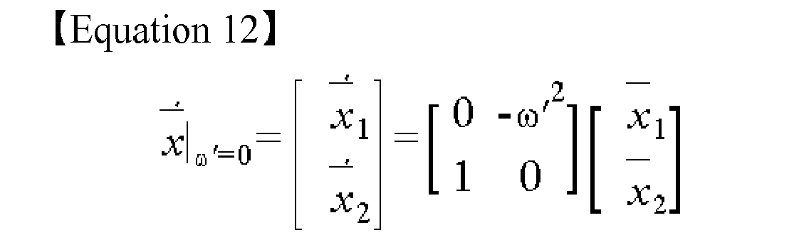
Equation 12.
- Next, operation of bandwidth decision unit (83) will be described.
- The following Equations may be derived when average of each variable is used.


- ω'2 - ω2 in Equation 15 may be simplified as 2ω'(ω' - ω)(@ω'≅ω), and therefore, an estimated frequency of the bandwidth decision unit (83) may be decided to have the following control bandwidth.

- Thus, with reference to Equation 16, it can be appreciated that the control bandwidth is decided by gain of the gain setting unit (82c) of the frequency estimator (82). Thus, the gain of the gain setting unit (82c) is preferably selected of a value higher than an operation frequency of the motor (2).
- The deductor (84a) of determinator (84) outputs a difference between ω' a frequency of estimated current which is an output of the frequency estimator (82) and ω INV a frequency of voltage outputted by the inverter (50), and the decision unit (84b) outputs 'F' as being determined as failure in start when the difference of the deductor (84a) exceeds Δω which is a preset allowable frequency scope, and outputs 'S' as being determined as success of start when the difference is within the preset allowable frequency scope.
- When the sensor-less operation of 3-phase motor (2) is normal, a current frequency which is the same as the frequency of voltage applied by the inverter (50) must be outputted. At this time, the frequency ω1 of voltage applied by the inverter (50) is a variable known by the higher controller (not shown), the frequency ω' of phase current inputted to the motor (2) estimated by the frequency estimator (82) during normal operation must be same (ω1 = ω'). That is, when an output of the frequency estimator (82) is same as an output voltage frequency of the inverter (50), it means that the 3-phase motor (2) operates normally, and when the value is different, it means that the 3-phase motor (2) is determined as having developed a problem on the sensor-less operation, such that the higher controller stops the operation and may restart.
- At this time, when the input ω' c of the frequency estimator (82) is selected as an amount of value inoperable by the motor (2), and when the start of the motor (2) is not realized, the output of the frequency estimator (82) becomes ω' c to easily determine whether the motor (2) has successfully started.
- As noted from the foregoing, the apparatus (80) can measure all three currents inputted to the motor (2), or measure one or two currents, where the higher controller determines that the start of the motor (2) has failed when 'S' is not outputted from all currents.
- Although embodiments have been described with reference to a number of illustrative embodiments thereof, it should be understood that numerous other modifications and embodiments can be devised by those skilled in the art that will fall within the spirit and scope of the principles of this disclosure. More particularly, various variations and modifications are possible in the component parts and/or arrangements of the subject combination arrangement within the scope of the disclosure, the drawings and the appended claims.
Claims (6)
- An apparatus (80) for determining start of electric machine, characterized by:a converter (81) configured to output a first AC (Alternating Current) signal corresponding to a frequency component of at least one phase current inputted from an inverter (50) to a 3-phase motor (2) and a second AC signal 90 degree lagged in phase angle from the first AC signal;an estimator (82) configured to estimate a frequency from the second AC signal; anda determinator (84) configured to determine whether the 3-phase motor (2) has started using a difference between the frequency estimated by the estimator (82) and a frequency of an output voltage of the inverter (50).
- The apparatus (80) of claim 1, further characterized by a bandwidth decision unit (83) configured to decide a control bandwidth of the estimator (82).
- The apparatus (80) of claim 2, characterized in that a control bandwidth decided by the bandwidth decision unit (83) is decided by a gain of the estimator (82).
- The apparatus (80) of claim 3, characterized in that the gain of the estimator (82) is selected of a value higher than an operation frequency of the 3-phase motor (2).
- The apparatus (80) of any one claim of 1 to 3, characterized in that the estimator (82) receives a positive input frequency inoperable by the motor (2) to output the input frequency when start of the motor (2) is not made and to determine whether the start of the motor (2) has successfully made.
- The apparatus (80) of any one claim of 1 to 4, characterized in that the determinator (84) determines that the start has failed when a difference between the frequency estimated by the estimator (82) and the frequency of output voltage of the inverter (50).
Applications Claiming Priority (1)
| Application Number | Priority Date | Filing Date | Title |
|---|---|---|---|
| KR1020130076954A KR101754441B1 (en) | 2013-07-02 | 2013-07-02 | Apparatus for determining start of electric motor |
Publications (3)
| Publication Number | Publication Date |
|---|---|
| EP2822174A2 true EP2822174A2 (en) | 2015-01-07 |
| EP2822174A3 EP2822174A3 (en) | 2015-10-07 |
| EP2822174B1 EP2822174B1 (en) | 2018-04-25 |
Family
ID=51063266
Family Applications (1)
| Application Number | Title | Priority Date | Filing Date |
|---|---|---|---|
| EP14173425.1A Not-in-force EP2822174B1 (en) | 2013-07-02 | 2014-06-23 | Apparatus for determining start of electric machine |
Country Status (6)
| Country | Link |
|---|---|
| US (1) | US9660562B2 (en) |
| EP (1) | EP2822174B1 (en) |
| JP (1) | JP6139476B2 (en) |
| KR (1) | KR101754441B1 (en) |
| CN (1) | CN104283464B (en) |
| ES (1) | ES2678081T3 (en) |
Families Citing this family (5)
| Publication number | Priority date | Publication date | Assignee | Title |
|---|---|---|---|---|
| KR20140116728A (en) * | 2013-03-25 | 2014-10-06 | 엘지전자 주식회사 | Apparatus and method for initially driving a sensorless bldc motor |
| KR102676718B1 (en) * | 2018-03-14 | 2024-06-19 | 현대자동차주식회사 | Control method and control system of motor rotation speed |
| JP7515095B2 (en) * | 2019-04-24 | 2024-07-12 | パナソニックIpマネジメント株式会社 | Electric tool |
| JP7465190B2 (en) * | 2020-10-12 | 2024-04-10 | パナソニックホールディングス株式会社 | Electric tool, motor control method and program |
| CN113346812B (en) * | 2021-05-31 | 2022-10-28 | 广东美芝制冷设备有限公司 | Compressor control parameter adjusting method, device, equipment and storage medium |
Family Cites Families (11)
| Publication number | Priority date | Publication date | Assignee | Title |
|---|---|---|---|---|
| JPH04275098A (en) * | 1991-02-27 | 1992-09-30 | Matsushita Electric Ind Co Ltd | Pulse motor control circuit |
| US6014007A (en) | 1998-09-29 | 2000-01-11 | Allen-Bradley Company Llc | Method and apparatus for starting an AC drive into a rotating motor |
| JP3627902B2 (en) | 1998-12-25 | 2005-03-09 | ダイキン工業株式会社 | Method and apparatus for detecting lock in compressor drive device |
| JP3577245B2 (en) | 1999-08-05 | 2004-10-13 | シャープ株式会社 | Motor start control device |
| JP4958342B2 (en) | 2001-05-31 | 2012-06-20 | 日本電産コパル株式会社 | Ultrasonic motor control circuit |
| US7423395B2 (en) * | 2002-07-08 | 2008-09-09 | Kabushiki Kaisha Yaskawa Denki | Sensorless vector control method for alternating-current motor and control apparatus therefor |
| JP3719426B2 (en) * | 2002-07-08 | 2005-11-24 | 株式会社安川電機 | AC motor control method and control apparatus |
| JP4281376B2 (en) | 2003-02-20 | 2009-06-17 | 三菱電機株式会社 | Electric motor drive |
| JP2009254191A (en) | 2008-04-09 | 2009-10-29 | Sharp Corp | Motor controller, compressor, refrigerating apparatus, and air conditioner |
| US8816622B2 (en) | 2010-07-27 | 2014-08-26 | Mitsubishi Electric Corporation | Control apparatus for rotating machine |
| WO2013116232A2 (en) * | 2012-01-31 | 2013-08-08 | Shapery, Sandor Wayne | System and method for inductive power transfer and robust position sensing |
-
2013
- 2013-07-02 KR KR1020130076954A patent/KR101754441B1/en active Active
-
2014
- 2014-06-19 US US14/309,676 patent/US9660562B2/en not_active Expired - Fee Related
- 2014-06-23 ES ES14173425.1T patent/ES2678081T3/en active Active
- 2014-06-23 EP EP14173425.1A patent/EP2822174B1/en not_active Not-in-force
- 2014-07-02 CN CN201410313522.7A patent/CN104283464B/en not_active Expired - Fee Related
- 2014-07-02 JP JP2014136720A patent/JP6139476B2/en not_active Expired - Fee Related
Non-Patent Citations (1)
| Title |
|---|
| None |
Also Published As
| Publication number | Publication date |
|---|---|
| KR101754441B1 (en) | 2017-07-05 |
| US20150008853A1 (en) | 2015-01-08 |
| ES2678081T3 (en) | 2018-08-08 |
| KR20150004032A (en) | 2015-01-12 |
| CN104283464A (en) | 2015-01-14 |
| EP2822174A3 (en) | 2015-10-07 |
| CN104283464B (en) | 2017-07-25 |
| EP2822174B1 (en) | 2018-04-25 |
| JP6139476B2 (en) | 2017-05-31 |
| US9660562B2 (en) | 2017-05-23 |
| JP2015015886A (en) | 2015-01-22 |
Similar Documents
| Publication | Publication Date | Title |
|---|---|---|
| US8963461B2 (en) | Motor control device | |
| KR102108911B1 (en) | Drive system and inverter device | |
| EP2426814B1 (en) | Power conversion device | |
| US10411633B2 (en) | Control device for AC rotating machine | |
| EP1107446A2 (en) | Position-sensorless controlling method of synchronous motor | |
| EP2822174B1 (en) | Apparatus for determining start of electric machine | |
| EP2600518A1 (en) | Control apparatus for ac rotating machine | |
| EP2173027A2 (en) | Control device for induction motor | |
| JP6726390B2 (en) | Controller for permanent magnet type synchronous motor | |
| WO2017214499A1 (en) | Restart strategy for synchronous reluctance machines | |
| EP3719991B1 (en) | Electric motor control method and electric motor control device | |
| EP2811643A1 (en) | Device for controlling alternating current rotating machine | |
| EP2093878B1 (en) | Controller of ac rotating machine | |
| US20170257041A1 (en) | Acceleration method for v/f controlled induction motor in flux-weakening region | |
| JP6591794B2 (en) | Induction machine power converter, second-order time constant measuring method and speed control method | |
| KR20120106449A (en) | On-line parameter correcting method for sensorless control of interior permanent magnet synchronous motor | |
| EP3093985B1 (en) | Control device for electric motor | |
| JP6104021B2 (en) | AC rotating machine control device | |
| JP5869308B2 (en) | Inverter device | |
| JP6485821B1 (en) | Motor control device | |
| EP3214753B1 (en) | Power conversion device and method for controlling power conversion device | |
| KR20200004634A (en) | Apparatus for controlling motor of vehicle | |
| KR101786335B1 (en) | Apparatus for controlling drive | |
| JP6880805B2 (en) | Induction motor control device | |
| Wang et al. | Maximum torque output for volts/Hz controlled induction machines in flux-weakening region |
Legal Events
| Date | Code | Title | Description |
|---|---|---|---|
| PUAI | Public reference made under article 153(3) epc to a published international application that has entered the european phase |
Free format text: ORIGINAL CODE: 0009012 |
|
| 17P | Request for examination filed |
Effective date: 20140623 |
|
| AK | Designated contracting states |
Kind code of ref document: A2 Designated state(s): AL AT BE BG CH CY CZ DE DK EE ES FI FR GB GR HR HU IE IS IT LI LT LU LV MC MK MT NL NO PL PT RO RS SE SI SK SM TR |
|
| AX | Request for extension of the european patent |
Extension state: BA ME |
|
| PUAL | Search report despatched |
Free format text: ORIGINAL CODE: 0009013 |
|
| AK | Designated contracting states |
Kind code of ref document: A3 Designated state(s): AL AT BE BG CH CY CZ DE DK EE ES FI FR GB GR HR HU IE IS IT LI LT LU LV MC MK MT NL NO PL PT RO RS SE SI SK SM TR |
|
| AX | Request for extension of the european patent |
Extension state: BA ME |
|
| RIC1 | Information provided on ipc code assigned before grant |
Ipc: H02P 21/14 20060101ALI20150902BHEP Ipc: H02P 1/26 20060101AFI20150902BHEP Ipc: H02P 6/18 20060101ALI20150902BHEP |
|
| R17P | Request for examination filed (corrected) |
Effective date: 20160404 |
|
| RBV | Designated contracting states (corrected) |
Designated state(s): AL AT BE BG CH CY CZ DE DK EE ES FI FR GB GR HR HU IE IS IT LI LT LU LV MC MK MT NL NO PL PT RO RS SE SI SK SM TR |
|
| GRAP | Despatch of communication of intention to grant a patent |
Free format text: ORIGINAL CODE: EPIDOSNIGR1 |
|
| INTG | Intention to grant announced |
Effective date: 20171222 |
|
| GRAA | (expected) grant |
Free format text: ORIGINAL CODE: 0009210 |
|
| GRAS | Grant fee paid |
Free format text: ORIGINAL CODE: EPIDOSNIGR3 |
|
| AK | Designated contracting states |
Kind code of ref document: B1 Designated state(s): AL AT BE BG CH CY CZ DE DK EE ES FI FR GB GR HR HU IE IS IT LI LT LU LV MC MK MT NL NO PL PT RO RS SE SI SK SM TR |
|
| REG | Reference to a national code |
Ref country code: GB Ref legal event code: FG4D |
|
| REG | Reference to a national code |
Ref country code: CH Ref legal event code: EP |
|
| REG | Reference to a national code |
Ref country code: AT Ref legal event code: REF Ref document number: 993899 Country of ref document: AT Kind code of ref document: T Effective date: 20180515 |
|
| REG | Reference to a national code |
Ref country code: IE Ref legal event code: FG4D |
|
| REG | Reference to a national code |
Ref country code: DE Ref legal event code: R096 Ref document number: 602014024319 Country of ref document: DE |
|
| REG | Reference to a national code |
Ref country code: FR Ref legal event code: PLFP Year of fee payment: 5 |
|
| REG | Reference to a national code |
Ref country code: ES Ref legal event code: FG2A Ref document number: 2678081 Country of ref document: ES Kind code of ref document: T3 Effective date: 20180808 |
|
| REG | Reference to a national code |
Ref country code: NL Ref legal event code: MP Effective date: 20180425 |
|
| REG | Reference to a national code |
Ref country code: LT Ref legal event code: MG4D |
|
| PG25 | Lapsed in a contracting state [announced via postgrant information from national office to epo] |
Ref country code: NL Free format text: LAPSE BECAUSE OF FAILURE TO SUBMIT A TRANSLATION OF THE DESCRIPTION OR TO PAY THE FEE WITHIN THE PRESCRIBED TIME-LIMIT Effective date: 20180425 |
|
| PG25 | Lapsed in a contracting state [announced via postgrant information from national office to epo] |
Ref country code: NO Free format text: LAPSE BECAUSE OF FAILURE TO SUBMIT A TRANSLATION OF THE DESCRIPTION OR TO PAY THE FEE WITHIN THE PRESCRIBED TIME-LIMIT Effective date: 20180725 Ref country code: FI Free format text: LAPSE BECAUSE OF FAILURE TO SUBMIT A TRANSLATION OF THE DESCRIPTION OR TO PAY THE FEE WITHIN THE PRESCRIBED TIME-LIMIT Effective date: 20180425 Ref country code: LT Free format text: LAPSE BECAUSE OF FAILURE TO SUBMIT A TRANSLATION OF THE DESCRIPTION OR TO PAY THE FEE WITHIN THE PRESCRIBED TIME-LIMIT Effective date: 20180425 Ref country code: PL Free format text: LAPSE BECAUSE OF FAILURE TO SUBMIT A TRANSLATION OF THE DESCRIPTION OR TO PAY THE FEE WITHIN THE PRESCRIBED TIME-LIMIT Effective date: 20180425 Ref country code: SE Free format text: LAPSE BECAUSE OF FAILURE TO SUBMIT A TRANSLATION OF THE DESCRIPTION OR TO PAY THE FEE WITHIN THE PRESCRIBED TIME-LIMIT Effective date: 20180425 Ref country code: BG Free format text: LAPSE BECAUSE OF FAILURE TO SUBMIT A TRANSLATION OF THE DESCRIPTION OR TO PAY THE FEE WITHIN THE PRESCRIBED TIME-LIMIT Effective date: 20180725 |
|
| PG25 | Lapsed in a contracting state [announced via postgrant information from national office to epo] |
Ref country code: LV Free format text: LAPSE BECAUSE OF FAILURE TO SUBMIT A TRANSLATION OF THE DESCRIPTION OR TO PAY THE FEE WITHIN THE PRESCRIBED TIME-LIMIT Effective date: 20180425 Ref country code: RS Free format text: LAPSE BECAUSE OF FAILURE TO SUBMIT A TRANSLATION OF THE DESCRIPTION OR TO PAY THE FEE WITHIN THE PRESCRIBED TIME-LIMIT Effective date: 20180425 Ref country code: GR Free format text: LAPSE BECAUSE OF FAILURE TO SUBMIT A TRANSLATION OF THE DESCRIPTION OR TO PAY THE FEE WITHIN THE PRESCRIBED TIME-LIMIT Effective date: 20180726 Ref country code: HR Free format text: LAPSE BECAUSE OF FAILURE TO SUBMIT A TRANSLATION OF THE DESCRIPTION OR TO PAY THE FEE WITHIN THE PRESCRIBED TIME-LIMIT Effective date: 20180425 |
|
| REG | Reference to a national code |
Ref country code: AT Ref legal event code: MK05 Ref document number: 993899 Country of ref document: AT Kind code of ref document: T Effective date: 20180425 |
|
| PG25 | Lapsed in a contracting state [announced via postgrant information from national office to epo] |
Ref country code: PT Free format text: LAPSE BECAUSE OF FAILURE TO SUBMIT A TRANSLATION OF THE DESCRIPTION OR TO PAY THE FEE WITHIN THE PRESCRIBED TIME-LIMIT Effective date: 20180827 |
|
| REG | Reference to a national code |
Ref country code: DE Ref legal event code: R097 Ref document number: 602014024319 Country of ref document: DE |
|
| PG25 | Lapsed in a contracting state [announced via postgrant information from national office to epo] |
Ref country code: DK Free format text: LAPSE BECAUSE OF FAILURE TO SUBMIT A TRANSLATION OF THE DESCRIPTION OR TO PAY THE FEE WITHIN THE PRESCRIBED TIME-LIMIT Effective date: 20180425 Ref country code: EE Free format text: LAPSE BECAUSE OF FAILURE TO SUBMIT A TRANSLATION OF THE DESCRIPTION OR TO PAY THE FEE WITHIN THE PRESCRIBED TIME-LIMIT Effective date: 20180425 Ref country code: AT Free format text: LAPSE BECAUSE OF FAILURE TO SUBMIT A TRANSLATION OF THE DESCRIPTION OR TO PAY THE FEE WITHIN THE PRESCRIBED TIME-LIMIT Effective date: 20180425 Ref country code: SK Free format text: LAPSE BECAUSE OF FAILURE TO SUBMIT A TRANSLATION OF THE DESCRIPTION OR TO PAY THE FEE WITHIN THE PRESCRIBED TIME-LIMIT Effective date: 20180425 Ref country code: RO Free format text: LAPSE BECAUSE OF FAILURE TO SUBMIT A TRANSLATION OF THE DESCRIPTION OR TO PAY THE FEE WITHIN THE PRESCRIBED TIME-LIMIT Effective date: 20180425 Ref country code: CZ Free format text: LAPSE BECAUSE OF FAILURE TO SUBMIT A TRANSLATION OF THE DESCRIPTION OR TO PAY THE FEE WITHIN THE PRESCRIBED TIME-LIMIT Effective date: 20180425 |
|
| REG | Reference to a national code |
Ref country code: CH Ref legal event code: PL |
|
| PG25 | Lapsed in a contracting state [announced via postgrant information from national office to epo] |
Ref country code: SM Free format text: LAPSE BECAUSE OF FAILURE TO SUBMIT A TRANSLATION OF THE DESCRIPTION OR TO PAY THE FEE WITHIN THE PRESCRIBED TIME-LIMIT Effective date: 20180425 |
|
| PLBE | No opposition filed within time limit |
Free format text: ORIGINAL CODE: 0009261 |
|
| STAA | Information on the status of an ep patent application or granted ep patent |
Free format text: STATUS: NO OPPOSITION FILED WITHIN TIME LIMIT |
|
| REG | Reference to a national code |
Ref country code: BE Ref legal event code: MM Effective date: 20180630 |
|
| REG | Reference to a national code |
Ref country code: IE Ref legal event code: MM4A |
|
| PG25 | Lapsed in a contracting state [announced via postgrant information from national office to epo] |
Ref country code: MC Free format text: LAPSE BECAUSE OF FAILURE TO SUBMIT A TRANSLATION OF THE DESCRIPTION OR TO PAY THE FEE WITHIN THE PRESCRIBED TIME-LIMIT Effective date: 20180425 Ref country code: LU Free format text: LAPSE BECAUSE OF NON-PAYMENT OF DUE FEES Effective date: 20180623 |
|
| 26N | No opposition filed |
Effective date: 20190128 |
|
| PG25 | Lapsed in a contracting state [announced via postgrant information from national office to epo] |
Ref country code: LI Free format text: LAPSE BECAUSE OF NON-PAYMENT OF DUE FEES Effective date: 20180630 Ref country code: IE Free format text: LAPSE BECAUSE OF NON-PAYMENT OF DUE FEES Effective date: 20180623 Ref country code: CH Free format text: LAPSE BECAUSE OF NON-PAYMENT OF DUE FEES Effective date: 20180630 |
|
| PG25 | Lapsed in a contracting state [announced via postgrant information from national office to epo] |
Ref country code: BE Free format text: LAPSE BECAUSE OF NON-PAYMENT OF DUE FEES Effective date: 20180630 Ref country code: SI Free format text: LAPSE BECAUSE OF FAILURE TO SUBMIT A TRANSLATION OF THE DESCRIPTION OR TO PAY THE FEE WITHIN THE PRESCRIBED TIME-LIMIT Effective date: 20180425 |
|
| PG25 | Lapsed in a contracting state [announced via postgrant information from national office to epo] |
Ref country code: AL Free format text: LAPSE BECAUSE OF FAILURE TO SUBMIT A TRANSLATION OF THE DESCRIPTION OR TO PAY THE FEE WITHIN THE PRESCRIBED TIME-LIMIT Effective date: 20180425 |
|
| PG25 | Lapsed in a contracting state [announced via postgrant information from national office to epo] |
Ref country code: MT Free format text: LAPSE BECAUSE OF NON-PAYMENT OF DUE FEES Effective date: 20180623 |
|
| PG25 | Lapsed in a contracting state [announced via postgrant information from national office to epo] |
Ref country code: TR Free format text: LAPSE BECAUSE OF FAILURE TO SUBMIT A TRANSLATION OF THE DESCRIPTION OR TO PAY THE FEE WITHIN THE PRESCRIBED TIME-LIMIT Effective date: 20180425 |
|
| PG25 | Lapsed in a contracting state [announced via postgrant information from national office to epo] |
Ref country code: HU Free format text: LAPSE BECAUSE OF FAILURE TO SUBMIT A TRANSLATION OF THE DESCRIPTION OR TO PAY THE FEE WITHIN THE PRESCRIBED TIME-LIMIT; INVALID AB INITIO Effective date: 20140623 |
|
| PG25 | Lapsed in a contracting state [announced via postgrant information from national office to epo] |
Ref country code: CY Free format text: LAPSE BECAUSE OF FAILURE TO SUBMIT A TRANSLATION OF THE DESCRIPTION OR TO PAY THE FEE WITHIN THE PRESCRIBED TIME-LIMIT Effective date: 20180425 Ref country code: MK Free format text: LAPSE BECAUSE OF NON-PAYMENT OF DUE FEES Effective date: 20180425 |
|
| PGFP | Annual fee paid to national office [announced via postgrant information from national office to epo] |
Ref country code: FR Payment date: 20200306 Year of fee payment: 7 |
|
| PG25 | Lapsed in a contracting state [announced via postgrant information from national office to epo] |
Ref country code: IS Free format text: LAPSE BECAUSE OF FAILURE TO SUBMIT A TRANSLATION OF THE DESCRIPTION OR TO PAY THE FEE WITHIN THE PRESCRIBED TIME-LIMIT Effective date: 20180825 |
|
| PG25 | Lapsed in a contracting state [announced via postgrant information from national office to epo] |
Ref country code: FR Free format text: LAPSE BECAUSE OF NON-PAYMENT OF DUE FEES Effective date: 20210630 |
|
| PGFP | Annual fee paid to national office [announced via postgrant information from national office to epo] |
Ref country code: IT Payment date: 20220309 Year of fee payment: 9 |
|
| PGFP | Annual fee paid to national office [announced via postgrant information from national office to epo] |
Ref country code: GB Payment date: 20220405 Year of fee payment: 9 Ref country code: DE Payment date: 20220308 Year of fee payment: 9 |
|
| PGFP | Annual fee paid to national office [announced via postgrant information from national office to epo] |
Ref country code: ES Payment date: 20220711 Year of fee payment: 9 |
|
| REG | Reference to a national code |
Ref country code: DE Ref legal event code: R119 Ref document number: 602014024319 Country of ref document: DE |
|
| GBPC | Gb: european patent ceased through non-payment of renewal fee |
Effective date: 20230623 |
|
| PG25 | Lapsed in a contracting state [announced via postgrant information from national office to epo] |
Ref country code: DE Free format text: LAPSE BECAUSE OF NON-PAYMENT OF DUE FEES Effective date: 20240103 Ref country code: GB Free format text: LAPSE BECAUSE OF NON-PAYMENT OF DUE FEES Effective date: 20230623 |
|
| PG25 | Lapsed in a contracting state [announced via postgrant information from national office to epo] |
Ref country code: IT Free format text: LAPSE BECAUSE OF NON-PAYMENT OF DUE FEES Effective date: 20230623 |
|
| REG | Reference to a national code |
Ref country code: ES Ref legal event code: FD2A Effective date: 20240801 |
|
| PG25 | Lapsed in a contracting state [announced via postgrant information from national office to epo] |
Ref country code: ES Free format text: LAPSE BECAUSE OF NON-PAYMENT OF DUE FEES Effective date: 20230624 |
|
| PG25 | Lapsed in a contracting state [announced via postgrant information from national office to epo] |
Ref country code: ES Free format text: LAPSE BECAUSE OF NON-PAYMENT OF DUE FEES Effective date: 20230624 |